EP1132719B1 - Reflective measuring scale - Google Patents
Reflective measuring scale Download PDFInfo
- Publication number
- EP1132719B1 EP1132719B1 EP01104953A EP01104953A EP1132719B1 EP 1132719 B1 EP1132719 B1 EP 1132719B1 EP 01104953 A EP01104953 A EP 01104953A EP 01104953 A EP01104953 A EP 01104953A EP 1132719 B1 EP1132719 B1 EP 1132719B1
- Authority
- EP
- European Patent Office
- Prior art keywords
- graduated
- reflective
- layer
- measuring scale
- scale according
- Prior art date
- Legal status (The legal status is an assumption and is not a legal conclusion. Google has not performed a legal analysis and makes no representation as to the accuracy of the status listed.)
- Expired - Lifetime
Links
- 239000000758 substrate Substances 0.000 claims description 27
- 239000000463 material Substances 0.000 claims description 21
- 239000006096 absorbing agent Substances 0.000 claims description 14
- VYPSYNLAJGMNEJ-UHFFFAOYSA-N Silicium dioxide Chemical compound O=[Si]=O VYPSYNLAJGMNEJ-UHFFFAOYSA-N 0.000 claims description 6
- XUIMIQQOPSSXEZ-UHFFFAOYSA-N Silicon Chemical compound [Si] XUIMIQQOPSSXEZ-UHFFFAOYSA-N 0.000 claims description 6
- 230000005855 radiation Effects 0.000 claims description 6
- 229910052710 silicon Inorganic materials 0.000 claims description 6
- 239000010703 silicon Substances 0.000 claims description 6
- 229910000831 Steel Inorganic materials 0.000 claims description 5
- 239000010959 steel Substances 0.000 claims description 5
- 238000010521 absorption reaction Methods 0.000 claims description 4
- 229910044991 metal oxide Inorganic materials 0.000 claims description 3
- 150000004706 metal oxides Chemical class 0.000 claims description 3
- 239000000377 silicon dioxide Substances 0.000 claims description 3
- 230000002745 absorbent Effects 0.000 claims description 2
- 239000002250 absorbent Substances 0.000 claims description 2
- PNEYBMLMFCGWSK-UHFFFAOYSA-N aluminium oxide Inorganic materials [O-2].[O-2].[O-2].[Al+3].[Al+3] PNEYBMLMFCGWSK-UHFFFAOYSA-N 0.000 claims 1
- 229910052681 coesite Inorganic materials 0.000 claims 1
- 229910052593 corundum Inorganic materials 0.000 claims 1
- 229910052906 cristobalite Inorganic materials 0.000 claims 1
- 229910052682 stishovite Inorganic materials 0.000 claims 1
- 229910052905 tridymite Inorganic materials 0.000 claims 1
- 229910001845 yogo sapphire Inorganic materials 0.000 claims 1
- 238000005259 measurement Methods 0.000 description 27
- 238000000034 method Methods 0.000 description 17
- 229920002120 photoresistant polymer Polymers 0.000 description 7
- 238000002310 reflectometry Methods 0.000 description 7
- 238000004519 manufacturing process Methods 0.000 description 6
- VYZAMTAEIAYCRO-UHFFFAOYSA-N Chromium Chemical compound [Cr] VYZAMTAEIAYCRO-UHFFFAOYSA-N 0.000 description 5
- 239000011651 chromium Substances 0.000 description 5
- 229910052782 aluminium Inorganic materials 0.000 description 4
- XAGFODPZIPBFFR-UHFFFAOYSA-N aluminium Chemical compound [Al] XAGFODPZIPBFFR-UHFFFAOYSA-N 0.000 description 4
- 238000011109 contamination Methods 0.000 description 4
- 230000003287 optical effect Effects 0.000 description 4
- 229910004298 SiO 2 Inorganic materials 0.000 description 3
- 229910052804 chromium Inorganic materials 0.000 description 3
- 230000000694 effects Effects 0.000 description 3
- BASFCYQUMIYNBI-UHFFFAOYSA-N platinum Chemical compound [Pt] BASFCYQUMIYNBI-UHFFFAOYSA-N 0.000 description 3
- 238000005070 sampling Methods 0.000 description 3
- 239000011248 coating agent Substances 0.000 description 2
- 238000000576 coating method Methods 0.000 description 2
- 230000001419 dependent effect Effects 0.000 description 2
- 238000000206 photolithography Methods 0.000 description 2
- 238000005240 physical vapour deposition Methods 0.000 description 2
- 235000012239 silicon dioxide Nutrition 0.000 description 2
- 238000004544 sputter deposition Methods 0.000 description 2
- 239000010936 titanium Substances 0.000 description 2
- 229910018072 Al 2 O 3 Inorganic materials 0.000 description 1
- 229910021569 Manganese fluoride Inorganic materials 0.000 description 1
- ZOKXTWBITQBERF-UHFFFAOYSA-N Molybdenum Chemical compound [Mo] ZOKXTWBITQBERF-UHFFFAOYSA-N 0.000 description 1
- RTAQQCXQSZGOHL-UHFFFAOYSA-N Titanium Chemical compound [Ti] RTAQQCXQSZGOHL-UHFFFAOYSA-N 0.000 description 1
- WGLPBDUCMAPZCE-UHFFFAOYSA-N Trioxochromium Chemical compound O=[Cr](=O)=O WGLPBDUCMAPZCE-UHFFFAOYSA-N 0.000 description 1
- 238000005299 abrasion Methods 0.000 description 1
- 229910000423 chromium oxide Inorganic materials 0.000 description 1
- 239000002826 coolant Substances 0.000 description 1
- CTNMMTCXUUFYAP-UHFFFAOYSA-L difluoromanganese Chemical compound F[Mn]F CTNMMTCXUUFYAP-UHFFFAOYSA-L 0.000 description 1
- 238000011156 evaluation Methods 0.000 description 1
- PCHJSUWPFVWCPO-UHFFFAOYSA-N gold Chemical compound [Au] PCHJSUWPFVWCPO-UHFFFAOYSA-N 0.000 description 1
- 239000010931 gold Substances 0.000 description 1
- 229910052737 gold Inorganic materials 0.000 description 1
- 239000000314 lubricant Substances 0.000 description 1
- 229910052751 metal Inorganic materials 0.000 description 1
- 239000002184 metal Substances 0.000 description 1
- 229910052750 molybdenum Inorganic materials 0.000 description 1
- 239000011733 molybdenum Substances 0.000 description 1
- 230000005693 optoelectronics Effects 0.000 description 1
- TWNQGVIAIRXVLR-UHFFFAOYSA-N oxo(oxoalumanyloxy)alumane Chemical compound O=[Al]O[Al]=O TWNQGVIAIRXVLR-UHFFFAOYSA-N 0.000 description 1
- 238000005192 partition Methods 0.000 description 1
- 239000011295 pitch Substances 0.000 description 1
- 229910052697 platinum Inorganic materials 0.000 description 1
- 238000002360 preparation method Methods 0.000 description 1
- 230000035945 sensitivity Effects 0.000 description 1
- 229910001220 stainless steel Inorganic materials 0.000 description 1
- 238000010025 steaming Methods 0.000 description 1
- 229910052715 tantalum Inorganic materials 0.000 description 1
- GUVRBAGPIYLISA-UHFFFAOYSA-N tantalum atom Chemical compound [Ta] GUVRBAGPIYLISA-UHFFFAOYSA-N 0.000 description 1
- 229910052719 titanium Inorganic materials 0.000 description 1
- WFKWXMTUELFFGS-UHFFFAOYSA-N tungsten Chemical compound [W] WFKWXMTUELFFGS-UHFFFAOYSA-N 0.000 description 1
- 229910052721 tungsten Inorganic materials 0.000 description 1
- 239000010937 tungsten Substances 0.000 description 1
- 238000007740 vapor deposition Methods 0.000 description 1
Images

Classifications
-
- G—PHYSICS
- G02—OPTICS
- G02B—OPTICAL ELEMENTS, SYSTEMS OR APPARATUS
- G02B5/00—Optical elements other than lenses
- G02B5/08—Mirrors
-
- G—PHYSICS
- G01—MEASURING; TESTING
- G01D—MEASURING NOT SPECIALLY ADAPTED FOR A SPECIFIC VARIABLE; ARRANGEMENTS FOR MEASURING TWO OR MORE VARIABLES NOT COVERED IN A SINGLE OTHER SUBCLASS; TARIFF METERING APPARATUS; MEASURING OR TESTING NOT OTHERWISE PROVIDED FOR
- G01D5/00—Mechanical means for transferring the output of a sensing member; Means for converting the output of a sensing member to another variable where the form or nature of the sensing member does not constrain the means for converting; Transducers not specially adapted for a specific variable
- G01D5/26—Mechanical means for transferring the output of a sensing member; Means for converting the output of a sensing member to another variable where the form or nature of the sensing member does not constrain the means for converting; Transducers not specially adapted for a specific variable characterised by optical transfer means, i.e. using infrared, visible, or ultraviolet light
- G01D5/32—Mechanical means for transferring the output of a sensing member; Means for converting the output of a sensing member to another variable where the form or nature of the sensing member does not constrain the means for converting; Transducers not specially adapted for a specific variable characterised by optical transfer means, i.e. using infrared, visible, or ultraviolet light with attenuation or whole or partial obturation of beams of light
- G01D5/34—Mechanical means for transferring the output of a sensing member; Means for converting the output of a sensing member to another variable where the form or nature of the sensing member does not constrain the means for converting; Transducers not specially adapted for a specific variable characterised by optical transfer means, i.e. using infrared, visible, or ultraviolet light with attenuation or whole or partial obturation of beams of light the beams of light being detected by photocells
- G01D5/347—Mechanical means for transferring the output of a sensing member; Means for converting the output of a sensing member to another variable where the form or nature of the sensing member does not constrain the means for converting; Transducers not specially adapted for a specific variable characterised by optical transfer means, i.e. using infrared, visible, or ultraviolet light with attenuation or whole or partial obturation of beams of light the beams of light being detected by photocells using displacement encoding scales
- G01D5/34707—Scales; Discs, e.g. fixation, fabrication, compensation
Definitions
- the present invention relates to a reflection measurement graduation.
- Optical incident-light position-measuring devices usually comprise a Reflection measuring graduation and a relatively movable scanning unit.
- a light source On the part of the scanning unit, a light source is usually arranged, the emits a light beam in the direction of the reflection measurement graduation. From there there is a return reflection in the direction of the scanning unit, where the shift-dependent modulated light bundles if necessary by one or more scanning divisions occurs and finally by an optoelectronic detector array is detected.
- the thus generated, shift-modulated Sampling signals are then transmitted via a downstream evaluation unit further processed.
- Known reflection measurement graduations that are used in these measuring devices usually consist of a carrier substrate on which alternating line portions with different reflection properties are arranged in the measuring direction.
- a full-surface coating with chromium steel carrier substrate can be provided on a steel carrier substrate a full-surface coating with chromium.
- absorbing or low-reflective subregions of chromium oxide Cr 2 O 3 are arranged on the chromium layer.
- the highly reflective subregions are formed by the exposed chrome subregions.
- Such reflection measurement pitches are subject to a number of requirements posed.
- u.a. the highest possible abrasion resistance, a high reflectivity in the highly reflective subregions, the greatest possible absorption in the low-reflecting Teü Hochen and to impart the lowest possible sensitivity to contamination.
- the above-explained variants of a reflection measurement graduation now turns out to be relatively sensitive to pollution. This reduces For example, when it comes to contamination with coolants or lubricants, the reflectivity of the highly reflective subregions, while the reflectivity in the slightly reflective subregions increases significantly. Overall results in the event of contamination, a significantly reduced degree of modulation of Scanning signals when this measurement division in an optical incident light position measuring device is used.
- EP 0 773 458 A1 also discloses an incident-light phase grating in which the different, each reflecting subregions one each different pahsenschiebende effect on the incident and then exercise reflected radiation.
- EP 0 497 742 A1 proposes an incident light measuring graduation, in the highly reflective aluminum and SiO 2 layer on a steel substrate be applied over the entire surface and in turn the low-reflective Chrome bars of the division structure.
- the object of the present invention is a reflection measurement graduation specify that is as insensitive to contamination as possible.
- the reflection measurement division according to the invention offers in comparison to Previous solutions have a number of advantages. So, for one thing ensured that even in the case of a possible pollution a high Degree of modulation of the sampling remains ensured if such Reflection measurement graduation in an optical incident-light position-measuring device is used. It is also a case of pollution both sufficiently high reflectivity in the highly reflective sub-areas as also a sufficiently high absorption in the low-reflective Subareas of the measurement division before.
- the reflection measurement graduation according to the invention is also distinguished by a high mechanical load capacity.
- a for the preparation of the inventive reflection measurement used method requires only a small number of Process steps; such is just a single structuring step necessary. Likewise, there are no procedurally complex processes when setting the required layer thicknesses.
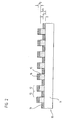
- Figure 1 is a plan view of a part of an inventively designed Reflection measurement division 10 shown.
- the reflection measuring graduation 10 formed as a linear incremental graduation, the alternately arranged in the x-direction of the first and second portions 12, 13, which in a track 15 on a support substrate 11th are arranged.
- the first portions 12 are highly reflective designed; the second portions 13 are designed to be slightly reflective.
- inventive design of the sections 12, 13 is to the following description in Figures 2 and 3a -3e referenced.
- the Subregions 12, 13 with different reflective properties respectively the identical geometric shape and consist of narrow Rectangles, the width b in the x direction and the length l in the y direction have. From the sum of the widths b of two subregions 12, 13 results yourself for the resolution of a corresponding incremental Position measuring device relevant graduation period TP.
- the direction indicated by x, along which the subregions 12, 13 arranged are, corresponds to the direction of measurement. Along this direction moves in a corresponding incident light position measuring a - Not shown - scanning relative to the reflection measurement division 10th
- the reflection measurement division according to the invention also alternatively be formed rotatory; it is natural too possible to design an absolutely coded measuring graduation according to the invention, in which the subregions 12, 13 different widths b in the x direction have etc.
- carrier substrate 11 of the reflection measuring graduation 10 is in this case polished Steel provided, which has a high reflectivity for the incident radiation having. Usual thicknesses of the carrier substrate 11 are in the range between 1mm and 15mm.
- carrier substrates 11 for example, other metallic reflectors made of titanium Ti, Tungsten W, molybdenum Mo, platinum Pt, tantalum Ta or chromium Cr.
- the low-reflection, second partial regions 13 of the reflection measuring graduation 10 according to the invention consist of an absorber layer 14 which is applied directly to the carrier substrate 11.
- the absorber layer 14 would also be weak absorbing metal oxides into consideration.
- the highly reflective, first portions 12 are according to the invention of several partial layers 15, 16 with different refractive indices, which are arranged one above the other on the carrier substrate 11 and as an interference filter Act.
- the highly reflective portions 12 of the reflection measurement graduation 10 are accordingly according to the invention as a dielectric reflection interference filter educated.
- the partial layer 15 arranged directly on the carrier substrate 11 is referred to below as the first partial layer 15, which has a refractive index n 1 .
- the uppermost sub-layer 16 arranged above is referred to below as the second sub-layer 16 and has the refractive index n 2 .
- the refractive index n 1 of the first sub-layer 15, which is arranged directly on the carrier substrate 11, is chosen to be significantly smaller than the refractive index n 2 of the second sub-layer 16 arranged above it in order to achieve the desired interference effect.
- silicon dioxide SiO 2 is selected as the material for the low-refractive, first partial layer 15.
- Aluminum oxide Al 2 O 3 or else manganese fluoride MgF 2 would also be considered as alternative materials for the first part-layer 15.
- silicon Si is selected, ie the identical material as for the absorber layer 14.
- the refractive index n 2 of the second partial layer 16 is preferably chosen to be greater than or equal to 2.2, ie n 2 ⁇ 2.2.
- the identical alternative materials come into consideration as for the absorber layer 14, ie, for example, weakly absorbing metal oxides.
- the inventive design ensures the highly reflective portions 12 a high mechanical strength.
- Reflection measurement division 10 results from the fact that for the absorber layer 14 and the second partial layer 16 identical Material is selected, in the present example silicon Si.
- identical Material is selected, in the present example silicon Si.
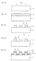
- FIG. 3 a shows how in a first step of the illustrated exemplary embodiment of the method on the carrier substrate 11 in the form of polished steel, a first partial layer is applied over a PVD method, eg vapor deposition or sputtering.
- a PVD method eg vapor deposition or sputtering.
- silicon dioxide SiO 2 is provided as explained above.
- the areal first sub-layer 15 is structured such that only in the first sub-areas 12, the first sub-layer 15 remains while in between lying second sub-areas 13, the first sub-layer 15 completely again Will get removed.
- the result of this structuring step is shown in FIG 3c.
- Such structuring is carried out by means of a conventional photolithography method, on this is not closer.
- a second partial layer 16 becomes uniform the first and second portions 12, 13 applied, wherein in the example According to FIG. 3d, silicon Si as the material of the second partial layer 16 is applied.
- a conventional PVD method is chosen, such as steaming or Sputtering.
- the materials for the different partial layers 15, 16 are selected with regard to their refractive indices n 1 , n 2 such that a dielectric reflection interference filter is formed in the region of the highly reflective first partial regions 13.
- the refractive index n 2 of the second partial layer 16 is in this case significantly greater than the refractive index n 1 of the first partial layer 15.
- the thicknesses d 1 , d 2 of the two partial layers 15, 16 are set as indicated above.
- FIG. 3e finally shows the finished reflection measurement graduation 10.
- the subsequent procedure instead of the process steps in FIGS. 3a and 3b, to to come to a structure, as shown in Figure 3c.
- This is in a first method step, the carrier substrate 11 over the entire surface coated with a photoresist.
- the photoresist is then over a Photolithography process is structured so that partial areas on the Carrier substrate 11 with photoresist and portions without photoresist result, which correspond to the subregions 12, 13 in Figure 3c. thereupon is the entire surface of the first sub-layer 15 on the support substrate 11 inclusive applied structured photoresist.
- the next process step will be then those subregions removed, in which those photoresist under the first sub-layer 15 is located, so that the structure according to Figure 3c results; then the procedure is as explained above.
Landscapes
- Physics & Mathematics (AREA)
- General Physics & Mathematics (AREA)
- Optics & Photonics (AREA)
- Optical Transform (AREA)
- Optical Elements Other Than Lenses (AREA)
- Length Measuring Devices By Optical Means (AREA)
Description
Die vorliegende Erfindung betrifft eine Reflexions-Messteilung.The present invention relates to a reflection measurement graduation.
Optische Auflicht-Positionsmesseinrichtungen umfassen üblicherweise eine Reflexions-Messteilung sowie eine relativ hierzu bewegliche Abtasteinheit. Auf Seiten der Abtasteinheit ist in der Regel eine Lichtquelle angeordnet, die ein Lichtbündel in Richtung der Reflexions-Messteilung emittiert. Von dort erfolgt eine Rückreflexion in Richtung der Abtasteinheit, wo das verschiebungsabhängig modulierte Lichtbündel ggf. durch ein oder mehrere Abtastteilungen tritt und schließlich von einer optoelektronischen Detektoranordnung erfaßt wird. Die derart erzeugten, verschiebungsabhängig modulierten Abtastsignale werden dann über eine nachgeordnete Auswerteeinheit weiterverarbeitet.Optical incident-light position-measuring devices usually comprise a Reflection measuring graduation and a relatively movable scanning unit. On the part of the scanning unit, a light source is usually arranged, the emits a light beam in the direction of the reflection measurement graduation. From there there is a return reflection in the direction of the scanning unit, where the shift-dependent modulated light bundles if necessary by one or more scanning divisions occurs and finally by an optoelectronic detector array is detected. The thus generated, shift-modulated Sampling signals are then transmitted via a downstream evaluation unit further processed.
Bekannte Reflexions-Messteilungen, die in diesen Messeinrichtungen eingesetzt werden, bestehen in der Regel aus einem Trägersubstrat, auf dem in Messrichtung alternierend strichfömige Teilbereiche mit unterschiedlichen Reflexionseigenschaften angeordnet sind. Beispielsweise kann auf einem Stahl-Trägersubstrat eine ganzflächige Beschichtung mit Chrom vorgesehen Stahl-Trägersubstrat eine ganzflächige Beschichtung mit Chrom vorgesehen werden. Auf der Chrom-Schicht sind dann wiederum absorbierende bzw. geringreflektierende Teilbereiche aus Chromoxid Cr2O3 angeordnet. Die hochreflektierenden Teilbereiche werden durch die freiliegenden Chrom-Teilbereiche gebildet.Known reflection measurement graduations that are used in these measuring devices usually consist of a carrier substrate on which alternating line portions with different reflection properties are arranged in the measuring direction. For example, a full-surface coating with chromium steel carrier substrate can be provided on a steel carrier substrate a full-surface coating with chromium. In turn, absorbing or low-reflective subregions of chromium oxide Cr 2 O 3 are arranged on the chromium layer. The highly reflective subregions are formed by the exposed chrome subregions.
Eine weitere Reflexions-Messteilung ist aus der US 4,644,156 bekannt. Auf einem Aluminium-Trägersubstrat werden absorbierende Teilbereiche durch einen Photolack ausgebildet. Die hochreflektierenden Teilbereiche werden wiederum durch die freiliegenden Aluminium-Teilbereiche gebildet.Another reflection measurement graduation is known from US 4,644,156. On An aluminum support substrate undergoes absorbent portions formed a photoresist. The highly reflective subregions are again formed by the exposed aluminum sections.
An derartige Reflexions-Messteilungen werden eine Reihe von Anforderungen gestellt. In diesem Zusammenhang sind u.a. eine möglichst hohe Abriebfestigkeit, eine große Reflektivität in den hochreflektierenden Teilbereichen, eine möglichst große Absorption in den geringreflektierenden Teübereichen sowie eine möglichst geringe Verschmutzungsempfindlichkeit aufzuführen. Die oben erläuterten Varianten einer Reflexions-Messteilung weist sich nunmehr als relativ verschmutzungsempfindlich. So verringert sich bei einer Verschmutzung mit Kühl- oder Schmiermitteln etwa die Reflektivität der hochreflektierenden Teilbereiche signifikant, während die Reflektivität in den geringreflektierenden Teilbereichen deutlich ansteigt. Insgesamt resultiert im Verschmutzungsfall ein deutlich verringerter Modulationsgrad der Abtastsignale, wenn diese Messteilung in einer optischen Auflicht-Positionsmesseinrichtung eingesetzt wird.Such reflection measurement pitches are subject to a number of requirements posed. In this context, u.a. the highest possible abrasion resistance, a high reflectivity in the highly reflective subregions, the greatest possible absorption in the low-reflecting Teübereichen and to impart the lowest possible sensitivity to contamination. The above-explained variants of a reflection measurement graduation now turns out to be relatively sensitive to pollution. This reduces For example, when it comes to contamination with coolants or lubricants, the reflectivity of the highly reflective subregions, while the reflectivity in the slightly reflective subregions increases significantly. Overall results in the event of contamination, a significantly reduced degree of modulation of Scanning signals when this measurement division in an optical incident light position measuring device is used.
Aus der DE 1 279 944 ist zur Lösung dieser Problematik bereits vorgeschlagen worden, die geringreflektierenden Teilbereiche einer derartigen Reflexions-Messteilung als reflexvermindernde Interferenzschichten auszubilden. Die hochreflektierenden Teilbereiche werden hingegen als Gold-Schichten ausgelegt. Als nachteilig an einer derartigen Reflexions-Messteilung ist aufzuführen, dass diese lediglich über ein aufwendiges Herstellungsverfahren gefertigt werden kann. So müssen auf dem Metall-Substrat grossflächig die erforderlichen Schichtdicken der dielektrischen Interferenzschichten präzise eingestellt werden. Ferner ist insgesamt eine erhebliche Anzahl an einzelnen Teilschichten auf dem Trägersubstrat aufzubringen, was das Herstellungsverfahren zusätzlich aufwendig macht.DE 1 279 944 has already been proposed to solve this problem have, the low-reflective portions of such a reflection measurement graduation form as anti-reflection interference layers. The highly reflective subregions, on the other hand, are called gold layers designed. A disadvantage of such a reflection measurement graduation is to be listed, that these only have a complicated manufacturing process can be made. Thus, on the metal substrate, the large area must required layer thicknesses of the dielectric interference layers precisely be set. Furthermore, a total of a significant number of individual Apply partial layers on the carrier substrate, which is the manufacturing process additionally elaborate.
Aus der US 4,286,871 ist ein zweidimensionales Auflicht-Phasengitter bekannt, bei dem einzelne CeO2-Bereiche die einfallende Strahlung reflektieren. Die reflektierenden Teilbereiche sind hierbei in unterschiedlichen Höhen angeordnet, so dass die von den verschiedenen Teilbereichen reflektierten Strahlungsanteile jeweils bestimmte Phasenunterschiede aufweisen, je nachdem ob ggf. noch phasenbeeinflussende Zwischenschichten vor und nach der Reflexion durchlaufen werden oder nicht.From US 4,286,871 a two-dimensional incident light phase grating is known, in which individual CeO 2 regions reflect the incident radiation. The reflective subregions are hereby arranged at different heights, so that the radiation components reflected by the different subregions each have specific phase differences, depending on whether or not phase-influencing intermediate layers are passed through before or after the reflection.
Die EP 0 773 458 A1 offenbart ebenfalls ein Auflicht-Phasengitter , bei dem die verschiedenen, jeweils reflektierenden Teilbereiche jeweils eine unterschiedliche pahsenschiebende Wirkung auf die einfallende und dann reflektierte Strahlung ausüben.EP 0 773 458 A1 also discloses an incident-light phase grating in which the different, each reflecting subregions one each different pahsenschiebende effect on the incident and then exercise reflected radiation.
In der EP 0 497 742 A1 wird eine Auflicht-Messteilung vorgeschlagen, bei
der auf einem Stahlsubstrat hochreflektierende Aluminium- und SiO2schichte
ganzflächig aufgebracht werden und darauf wiederum die geringreflektierenden
Chromstege der Teilungsstruktur.EP 0 497 742 A1 proposes an incident light measuring graduation, in
the highly reflective aluminum and
Aus der JP 61-045923 ist schließlich eine weitere Auflicht-Teilung bekannt, bei der auf einem Aluminium-Substrat eine ganzflächige Alumit-Schicht aufgebracht wird, über der schließlich die lichtabsorbierenden Teilungsstege in der gewünschten Struktur angeordnet werden.From JP 61-045923, finally, a further reflected-light division is known, when on an aluminum substrate, a full-surface alumite layer is applied, over the finally the light-absorbing partition webs be arranged in the desired structure.
Aufgabe der vorliegenden Erfindung ist es, eine Reflexions-Messteilung anzugeben, die möglichst verschmutzungsunempfindlich ist.The object of the present invention is a reflection measurement graduation specify that is as insensitive to contamination as possible.
Diese Aufgabe wird gelöst durch eine Reflexions-Messteilung mit den Merkmalen des Anspruches 1. This object is achieved by a reflection measurement graduation with the Features of claim 1.
Vorteilhafte Ausführungsformen der erfindungsgemäßen Reflexions-Messteilung ergeben sich aus den Maßnahmen, die in den jeweils abhängigen Ansprüchen aufgeführt sind.Advantageous embodiments of the reflection measurement graduation according to the invention derive from the measures taken in each case dependent claims are listed.
Die erfindungsgemäße Reflexions-Messteilung bietet im Vergleich zu bisherigen Lösungen eine Reihe von Vorteilen. So ist zum einen sichergestellt, dass auch im Fall einer eventuellen Verschmutzung ein hoher Modulationsgrad der Abtastsignale gewährleistet bleibt, wenn eine derartige Reflexions-Messteilung in einer optischen Auflicht-Positionsmesseinrichtung eingesetzt wird. Es liegt auch im Verschmutzungsfall sowohl eine hinreichend große Reflektivität in den hochreflektierenden Teilbereichen als auch eine hinreichend hohe Absorption in den geringreflektierenden Teilbereichen der Messteilung vor.The reflection measurement division according to the invention offers in comparison to Previous solutions have a number of advantages. So, for one thing ensured that even in the case of a possible pollution a high Degree of modulation of the sampling remains ensured if such Reflection measurement graduation in an optical incident-light position-measuring device is used. It is also a case of pollution both sufficiently high reflectivity in the highly reflective sub-areas as also a sufficiently high absorption in the low-reflective Subareas of the measurement division before.
Ferner zeichnet sich die erfindungsgemässe Reflexions-Messteilung auch durch eine hohe mechanische Belastbarkeit aus.Furthermore, the reflection measurement graduation according to the invention is also distinguished by a high mechanical load capacity.
Ein zur Herstellung der erfindungsgemässen Reflexions-Messteüung genutzte Verfahren erfordert lediglich eine geringe Anzahl von Prozessschritten; so ist etwa lediglich ein einziger Strukturierungsschritt nötig. Ebenso ergeben sich keine verfahrenstechnisch aufwendigen Prozesse bei der Einstellung der erforderlichen Schichtdicken.A for the preparation of the inventive reflection measurement used method requires only a small number of Process steps; such is just a single structuring step necessary. Likewise, there are no procedurally complex processes when setting the required layer thicknesses.
Weitere Vorteile sowie Einzelheiten der vorliegenden Erfindung ergeben sich aus der nachfolgenden Beschreibung der beiliegenden Figuren.Further advantages and details of the present invention will become apparent from the following description of the accompanying figures.
Dabei zeigt
- Figur 1
- eine Draufsicht auf einen Teil eines Ausführungsbeispieles einer erfindungsgemäß ausgebildeten Reflexions-Messteilung;
Figur 2- eine Schnittansicht der Messteilung aus Figur 1;
- Figur 3a -3e
- jeweils ein bestimmtes Prozessstadium im Verlauf der Herstellung der erfindungsgemäßen Reflexions-Messteilung.
- FIG. 1
- a plan view of a portion of an embodiment of an inventively formed reflection measuring graduation;
- FIG. 2
- a sectional view of the measuring graduation of Figure 1;
- FIG. 3a-3e
- in each case a specific process stage in the course of the production of the reflection measurement graduation according to the invention.
In Figur 1 ist eine Draufsicht auf einen Teil einer erfindungsgemäß ausgebildeten
Reflexions-Messteilung 10 dargestellt. In diesem Ausführungsbeispiel
ist die Reflexions-Messteilung 10 als lineare Inkrementalteilung ausgebildet,
die aus alternierend in x-Richtung angeordneten ersten und zweiten Teilbereichen
12, 13 besteht, die in einer Spur 15 auf einem Trägersubstrat 11
angeordnet sind. Die ersten Teilbereiche 12 sind hierbei hochreflektierend
ausgelegt; die zweiten Teilbereiche 13 sind geringreflektierend ausgelegt.
Zur konkreten, erfindungsgemäßen Ausbildung der Teilbereiche 12, 13 sei
auf die nachfolgende Beschreibung in den Figuren 2 sowie 3a -3e verwiesen.In Figure 1 is a plan view of a part of an inventively designed
Im dargestellten Ausführungsbeispiel einer Inkrementalteilung weisen die
Teilbereiche 12, 13 mit unterschiedlichen Reflexionseigenschaften jeweils
die identische geometrische Form auf und bestehen aus schmalen
Rechtecken, die in x-Richtung die Breite b und in y-Richtung die Länge I
besitzen. Aus der Summe der Breiten b zweier Teilbereiche 12, 13 ergibt
sich die für die Auflösung einer entsprechenden inkrementalen
Positionsmesseinrichtung maßgebliche Teilungsperiode TP.In the illustrated embodiment of an incremental graduation, the
Die mit x bezeichnete Richtung, entlang der die Teilbereiche 12, 13 angeordnet
sind, entspricht hierbei der Messrichtung. Entlang dieser Richtung
bewegt sich in einer entsprechenden Auflicht-Positionsmesseinrichtung eine
- nicht dargestellte - Abtasteinheit relativ zur Reflexions-Messteilung 10.The direction indicated by x, along which the
Selbstverständlich kann die erfindungsgemäße Reflexions-Messteilung auch
alternativ hierzu rotatorisch ausgebildet werden; ebenso ist es natürlich
möglich, eine absolut-codierte Messteilung erfindungsgemäß auszugestalten,
bei der die Teilbereiche 12, 13 unterschiedliche Breiten b in x-Richtung
aufweisen usw.. Of course, the reflection measurement division according to the invention also
alternatively be formed rotatory; it is natural too
possible to design an absolutely coded measuring graduation according to the invention,
in which the
Anhand der Schnittansicht von Figur 2 sei nachfolgend der Aufbau eines
Ausführungsbeispieles der erfindungsgemäßen Reflexions-Messteilung 10
näher erläutert.Based on the sectional view of Figure 2 is below the structure of a
Embodiment of the
Als Trägersubstrat 11 der Reflexions-Messteilung 10 ist hierbei polierter
Stahl vorgesehen, der eine hohe Reflektivität für die einfallende Strahlung
aufweist. Übliche Dicken des Trägersubstrates 11 liegen im Bereich zwischen
1mm und 15mm. Alternativ zum gewählten Material wären grundsätzlich
auch andere hochreflektierende Materialien als Trägersubstrate 11 einsetzbar,
beispielsweise andere metallische Reflektoren aus Titan Ti,
Wolfram W, Molybdän Mo, Platin Pt, Tantal Ta oder Chrom Cr. Bei der Materialwahl
für das Trägersubstrat 11 ist neben den möglichst guten Reflexioriseigenschaften
ferner zu beachten, dass dieses auch mechanisch hinreichend
belastbar ist.As a
Die geringreflektierenden, zweiten Teilbereiche 13 der erfindungsgemäßen
Reflexions-Messteilung 10 bestehen aus einer Absorberschicht 14, die unmittelbar
auf dem Trägersubstrat 11 aufgebracht ist. Im dargestellten Ausführungsbeispiel
ist als Material für die Absorberschicht 14 Silizium Si vorgesehen,
das eine Absorptionskonstante k im Bereich zwischen k=0.1 und
k=0.5 aufweist. Die Dicke d2 der Absorberschicht 14 wird vorzugsweise im
Bereich zwischen d2=30nm und d2=50nm gewählt. Bei einer derartigen Materialwahl
bzw. Dimensionierung der Absorberschicht 14 ist sichergestellt,
dass sowohl im unverschmutzten als auch im ggf. verschmutzten Zustand
die zweiten Teilbereiche 13 der erfindungsgemäßen Reflexions-Messteilung
10 lediglich geringreflektierend für die einfallende Strahlung wirken. So resultiert
etwa auch im verschmutzten Zustand eine Restreflexion in den
zweiten Teilbereichen 13, die unter 10% liegt.The low-reflection, second
Als alternative Materialien für die Absorberschicht 14 kämen auch schwach
absorbierende Metall-Oxide in Betracht.As alternative materials for the
Die hochreflektierenden, ersten Teilbereiche 12 bestehen erfindungsgemäß
aus mehreren Teilschichten 15, 16 mit unterschiedlichen Brechungsindizes,
die übereinander auf dem Trägersubstrat 11 angeordnet sind und als Interferenzfilter
wirken. Die hochreflektierenden Teilbereiche 12 der Reflexions-Messteilung
10 sind demzufolge erfindungsgemäß als dielektrisches Reflexions-Interferenzfilter
ausgebildet.The highly reflective,
Im dargestellten Ausführungsbeispiel der Reflexions-Messteilung 10 sind
hierzu zwei Teilschichten 15, 16 mit deutlich unterschiedlichen Brechungsindizes
n1, n2 vorgesehen. Die unmittelbar auf dem Trägersubstrat 11 angeordnete
Teilschicht 15 sei nachfolgend als erste Teilschicht 15 bezeichnet,
die einen Brechungsindex n1 aufweist. Die darüber angeordnete, oberste
Teilschicht 16 wird nachfolgend als zweite Teilschicht 16 bezeichnet und
besitzt den Brechungsindex n2. Der Brechungsindex n1 der ersten Teilschicht
15, die unmittelbar auf dem Trägersubstrat 11 angeordnet ist, wird hierbei
deutlich kleiner gewählt als der Brechungsindex n2 der zweiten, darüber angeordneten
Teilschicht 16, um derart den gewünschten Interferenzeffekt zu
erzielen.In the illustrated exemplary embodiment of the
Im dargestellten Ausführungsbeispiel wird als Material für die niedrigbrechende,
erste Teilschicht 15 Siliziumdioxid SiO2 gewählt. Die Dicke d1 der
ersten Teilschicht 15 liegt vorzugsweise im Bereich zwischen d1=100nm und
d1=150nm. Der Brechungsindex n1 der ersten Teilschicht 15 liegt im vorliegenden
Ausführungsbeispiel im Bereich zwischen n1=1.3 und n1=1.7. Als
alternative Materialien kämen für die erste Teilschicht 15 ferner noch Aluminiumoxid
Al2O3 oder aber Manganfluorid MgF2 in Betracht.In the illustrated embodiment, silicon dioxide SiO 2 is selected as the material for the low-refractive, first
Für die hochbrechende, zweite Teilschicht 16 wird im vorliegenden Ausführungsbeispiel
erfindungsgemäß Silizium Si gewählt, d.h. das identische Material
wie für die Absorberschicht 14. Die Dicke d2 der zweiten Teilschicht 16
ist ferner identisch mit der Dicke d2 der Absorberschicht 14 und liegt demzufolge
im Bereich zwischen d2=30nm und d2=50nm. Der Brechungsindex n2
der zweiten Teilschicht 16 wird vorzugsweise größer oder gleich 2.2 gewählt,
d.h. n2≥2.2. Für die zweite Teilschicht 16 kommen die identischen alternativen
Materialien in Betracht wie für die Absorberschicht 14, d.h. beispielsweise
schwach absorbierende Metalloxide. For the high-index
Aufgrund der erläuterten, erfindungsgemäßen Ausbildung der ersten,
hochreflektierenden Teilbereiche 12 der Reflexions-Messteilung 10 ist sichergestellt,
dass auch im Fall einer eventuellen Verschmutzung eine hinreichend
hohe Reflektivität in diesen Teilbereichen 12 resultiert. So liegt auch
im Fall einer Verschmutzung immer noch eine Restreflektivität von 75%-80%
vor, d.h. es resultiert bei einer optischen Abtastung ein entsprechend
gut moduliertes Abtastsignal.Due to the explained, inventive design of the first,
highly
Desweiteren gewährleistet die erfindungsgemäße Ausgestaltung der hochreflektierenden Teilbereiche 12 eine hohe mechanische Belastbarkeit.Furthermore, the inventive design ensures the highly reflective portions 12 a high mechanical strength.
Ein weiterer wesentlicher Vorteil im Hinblick auf die Herstellung der erfindungsgemäßen
Reflexions-Messteilung 10 ergibt sich aus der Tatsache,
dass für die Absorberschicht 14 und die zweite Teilschicht 16 das identische
Material gewählt wird, im vorliegenden Beispiel Silizium Si. Die entsprechenden
Vorteile seien im Zusammenhang mit der nachfolgenden Beschreibung
eines Ausführungsbeispieles eines Verfahrens zur Herstellung einer
derartigen Reflexions-Messteilung 10 anhand der Figuren 3a - 3e erläutert.Another significant advantage in terms of the production of the invention
In Figur 3a ist hierbei dargestellt, wie in einem ersten Schritt des dargestellten
Ausführungsbeispieles des Verfahrens auf dem Trägersubstrat 11 in
Form von poliertem Stahl eine erste Teilschicht über ein PVD-Verfahren,
z.B. Bedampfen oder Sputtern, flächig aufgebracht wird. Als Material der
ersten Teilschicht 15, die in Figur 3b auf dem Trägersubstrat 11 gezeigt ist,
ist wie oben erläutert Siliziumdioxid SiO2 vorgesehen.FIG. 3 a shows how in a first step of the illustrated exemplary embodiment of the method on the
Im nächsten Verfahrensschritt wird im dargestellten Beispiel dann die flächige
erste Teilschicht 15 derart strukturiert, dass lediglich in ersten Teilbereichen
12 die erste Teilschicht 15 verbleibt, während in den dazwischen
liegenden zweiten Teilbereichen 13 die erste Teilschicht 15 wieder vollständig
entfernt wird. Das Ergebnis dieses Strukturierungs-Schrittes zeigt Figur
3c. Eine derartige Strukturierung erfolgt mit Hilfe eines üblichen Photolithographie-Verfahrens,
auf das hier nicht näher eingangen sei. In the next step in the illustrated example, the areal
Abschließend wird ganzflächig eine zweite Teilschicht 16 gleichmäßig auf
die ersten und zweiten Teilbereiche 12, 13 aufgebracht, wobei im Beispiel
gemäß Figur 3d hierzu Silizium Si als Material der zweiten Teilschicht 16
aufgebracht wird. Zum ganzflächigen Aufbringen der zweiten Teilschicht 16
wird wiederum ein übliches PVD-Verfahren gewählt, etwa Bedampfen oder
Sputtern.Finally, over the entire surface, a second
Wie oben bereits erläutert, werden die Materialien für die verschiedenen
Teilschichten 15, 16 derart im Hinblick auf ihre Brechungsindizes n1, n2 ausgewählt,
dass im Bereich der hoch reflektierenden ersten Teilbereiche 13 ein
dielektrisches Reflexions-Interferenzfilter ausgebildet wird. Der Brechungsindex
n2 der zweiten Teilschicht 16 ist hierbei deutlich größer als der Brechungsindex
n1 der ersten Teilschicht 15. Die Dicken d1, d2 der beiden Teilschichten
15, 16 werden wie oben bereits angegeben eingestellt. Figur 3e
zeigt schließlich die fertige Reflexions-Messteilung 10.As already explained above, the materials for the different
Neben dem dargestellten Ausführungsbeispiel existieren auch alternative
Varianten geeigneter Verfahren. So kann etwa das nachfolgende Vorgehen
anstelle der Prozessschritte in den Figuren 3a und 3b gewählt werden, um
zu einer Struktur zu kommen, wie sie in Figur 3c dargestellt ist. Hierbei wird
in einem ersten Verfahrensschritt das Trägersubstrat 11 ganzflächig mit
einem Photolack beschichtet. Der Photolack wird anschließend über ein
Photolithographie-Verfahren strukturiert, so dass Teilbereiche auf dem
Trägersubstrat 11 mit Photolack und Teilbereiche ohne Photolack
resultieren, die den Teilbereichen 12, 13 in Figur 3c entsprechen. Daraufhin
wird ganzflächig die erste Teilschicht 15 auf dem Trägersubstrat 11 inclusive
strukturiertem Photolack aufgebracht. Im nächsten Prozessschritt werden
dann diejenigen Teilbereiche entfernt, in sich denen Photolack unter der
ersten Teilschicht 15 befindet, so dass die Struktur gemäß Figur 3c
resultiert; anschließend wird wie oben erläutert vorgegangen.In addition to the illustrated embodiment, there are also alternative
Variants of suitable methods. For example, the subsequent procedure
instead of the process steps in FIGS. 3a and 3b, to
to come to a structure, as shown in Figure 3c. This is
in a first method step, the
Wie aus der vorhergehenden Beschreibung ersichtlich ist, erfordert das
Verfahren zur Herstellung einer Reflexions-Messteilung lediglich wenige
Prozessschritte. Im Ausführungsbeispeil der Figuren 3a-3e ist dabei nur
ein einziger Strukturierungssschritt erforderlich, wenn die erste Teilschicht
15 derart strukturiert wird, dass diese lediglich in den ersten Teilbereichen
12 verbleibt. Bei diesem Strukturierungssschritt ist zudem nur das Entfernen
einer relativ dünnen ersten Teilschicht 15 in den zweiten, gering
reflektierenden Teilbereichen nötig. Weiterhin ist vorteilhaft, dass das
Material für die oberste Teilschicht 16 der reflektierenden Teilbereiche 12
und die Absorberschicht 14 identisch ist, so dass im abschließenden Prozessschritt
dieses Material einfach ganzflächig aufgebracht werden kann.As can be seen from the foregoing description, this requires
Method for producing a reflection measurement graduation only a few
Process steps. In the Ausführungsbeispeil of Figures 3a-3e is only
a single structuring step is required if the
Claims (12)
- Reflective measuring scale comprising first and second graduated regions (12, 13) with different reflective properties, which extend in at least a first direction (x) on a highly reflective support substrate (11), whereinhighly reflective first graduated regions (12) comprise several graduated layers (15, 16) with different refractive indexes (n1, n2) on the support substrate (11), which act as a dielectric reflective interference filter andlow reflective second graduated regions (13) comprise at least one absorber layer (14) on the support substrate (11), wherein the second graduated regions (12) reflect incident radiation to a lesser degree than the first graduated regions.
- Reflective measuring scale according to Claim 1, wherein the highly reflective support substrate (11) is made from polished steel.
- Reflective measuring scale according to Claim 1, wherein the absorber layer (14) and the uppermost graduated layer (16) of the highly reflective second graduated regions (12) are made from identical material.
- Reflective measuring scale according to Claim 3, wherein silicon Si is selected as material for the absorber layer (14) and the uppermost graduated layer (16) of the highly reflective second graduated regions (12).
- Reflective measuring scale according to Claim 3, wherein the material for the absorber layer (14) and the uppermost graduated layer (16) of the highly reflective second graduated regions (12) has an absorption coefficient k in the range of between k=0.1 and k=0.5.
- Reflective measuring scale according to Claim 1, wherein the highly reflective first graduated regions (12) comprise a first and a second graduated layer (15, 16), which have a clearly different refractive index (n1, n2), and the first graduated layer (15) with the lower refractive index (n1) is arranged directly on the highly reflective support substrate (11).
- Reflective measuring scale according to Claim 6, wherein the refractive index n2 of the second graduated layer (16) is selected to be the higher refractive index in accordance with n2 ≥ 2.2.
- Reflective measuring scale according to Claim 6, wherein one of the following materials is selected for the second graduated layer: silicon Si, absorbent metal oxide.
- Reflective measuring scale according to Claim 6, wherein the thickness d2 of the second graduated layer (16) is selected to be between 30 nm and 50 nm.
- Reflective measuring scale according to Claim 6, wherein the refractive index n1 of the first graduated layer (15) lies between n1=1.3 and n2=1.7.
- Reflective measuring scale according to Claim 6, wherein one of the following materials is selected for the first graduated layer (15): SiO2, Al2O3.
- Reflective measuring scale according to Claim 6, wherein the thickness d1 of the first graduated layer (15) is selected to be between 100 nm and 150 nm.
Applications Claiming Priority (2)
| Application Number | Priority Date | Filing Date | Title |
|---|---|---|---|
| DE10011872A DE10011872A1 (en) | 2000-03-10 | 2000-03-10 | Reflection measurement graduation and method for producing the same |
| DE10011872 | 2000-03-10 |
Publications (2)
| Publication Number | Publication Date |
|---|---|
| EP1132719A1 EP1132719A1 (en) | 2001-09-12 |
| EP1132719B1 true EP1132719B1 (en) | 2005-06-01 |
Family
ID=7634333
Family Applications (1)
| Application Number | Title | Priority Date | Filing Date |
|---|---|---|---|
| EP01104953A Expired - Lifetime EP1132719B1 (en) | 2000-03-10 | 2001-03-01 | Reflective measuring scale |
Country Status (4)
| Country | Link |
|---|---|
| US (1) | US6671092B2 (en) |
| EP (1) | EP1132719B1 (en) |
| JP (1) | JP4545966B2 (en) |
| DE (2) | DE10011872A1 (en) |
Families Citing this family (12)
| Publication number | Priority date | Publication date | Assignee | Title |
|---|---|---|---|---|
| DE10150099A1 (en) * | 2001-10-11 | 2003-04-17 | Heidenhain Gmbh Dr Johannes | Production of a measuring rod used for electrical position measuring device comprises applying spacer layer on first reflecting layer, applying second reflecting layer, and structuring second reflecting layer by electron beam lithography |
| JP2004028862A (en) * | 2002-06-27 | 2004-01-29 | Harmonic Drive Syst Ind Co Ltd | Projection encoder |
| US20040035012A1 (en) * | 2002-08-26 | 2004-02-26 | Moehnke Stephanie J. | Measuring device having symbols viewable in multiple orientations |
| US7256938B2 (en) * | 2004-03-17 | 2007-08-14 | General Atomics | Method for making large scale multilayer dielectric diffraction gratings on thick substrates using reactive ion etching |
| US7321467B2 (en) * | 2005-05-26 | 2008-01-22 | Macronix International Co., Ltd. | Anti-reflection coating layer and design method thereof |
| WO2008146409A1 (en) * | 2007-06-01 | 2008-12-04 | Mitutoyo Corporation | Reflective encoder, scale thereof, and method for manufacturing scale |
| AT509101B1 (en) * | 2009-11-18 | 2011-10-15 | Victor Vasiloiu | INDUCTIVE MEASURING DEVICE FOR LENGTH AND ANGLE DETECTION |
| WO2012079239A1 (en) * | 2010-12-16 | 2012-06-21 | 苏州苏大维格光电科技股份有限公司 | Color filter |
| WO2015147756A1 (en) * | 2014-03-27 | 2015-10-01 | Heptagon Micro Optics Pte. Ltd. | Optical encoder system |
| JP7140495B2 (en) * | 2017-12-28 | 2022-09-21 | 株式会社ミツトヨ | Scale and its manufacturing method |
| JP2021131312A (en) * | 2020-02-20 | 2021-09-09 | 株式会社ミツトヨ | scale |
| WO2021201024A1 (en) * | 2020-03-31 | 2021-10-07 | 大日本印刷株式会社 | Reflective optical scale for encoder and reflective optical encoder |
Family Cites Families (12)
| Publication number | Priority date | Publication date | Assignee | Title |
|---|---|---|---|---|
| DE1279944B (en) * | 1965-09-15 | 1968-10-10 | Wenczler & Heidenhain | Graduation |
| US4374612A (en) | 1980-07-25 | 1983-02-22 | Canon Kabushiki Kaisha | Mark indicating device for optical apparatus |
| US4286871A (en) * | 1980-08-11 | 1981-09-01 | Keuffel & Esser Company | Photogrammetric measuring system |
| JPS5875004A (en) * | 1981-10-30 | 1983-05-06 | Mitsutoyo Mfg Co Ltd | Reflective scale for photoelectric displacement detector and its production |
| JPS60118912U (en) | 1984-01-18 | 1985-08-12 | アルプス電気株式会社 | Code wheel of reflective optical rotary encoder |
| JPS60161523A (en) * | 1984-02-02 | 1985-08-23 | Mitsutoyo Mfg Co Ltd | Three-dimensional measuring machine |
| JPS60217361A (en) * | 1984-04-13 | 1985-10-30 | Alps Electric Co Ltd | Light reflecting code plate |
| JPS6145923A (en) * | 1984-08-10 | 1986-03-06 | Aronshiya:Kk | Manufacture of rotary disk for reflection type rotary encoder |
| IT1245008B (en) * | 1991-01-25 | 1994-09-13 | Lamsweerde Edoardo Van | GRADUATED ELEMENT FOR REFLECTION OPTICAL READING AND PROCEDURE FOR ITS MANUFACTURE |
| JPH0933221A (en) * | 1995-07-21 | 1997-02-07 | Mitsutoyo Corp | Length measuring scale |
| EP0773458B1 (en) * | 1995-11-11 | 2000-03-08 | Dr. Johannes Heidenhain GmbH | Incident light phase grating |
| US6027815A (en) | 1996-11-06 | 2000-02-22 | Taiwan Semiconductor Manufacturing Company | Non-absorbing anti-reflective coated (ARC) reticle using thin dielectric films and method of forming reticle |
-
2000
- 2000-03-10 DE DE10011872A patent/DE10011872A1/en not_active Withdrawn
-
2001
- 2001-02-22 JP JP2001046694A patent/JP4545966B2/en not_active Expired - Fee Related
- 2001-03-01 DE DE50106355T patent/DE50106355D1/en not_active Expired - Lifetime
- 2001-03-01 EP EP01104953A patent/EP1132719B1/en not_active Expired - Lifetime
- 2001-03-08 US US09/801,449 patent/US6671092B2/en not_active Expired - Fee Related
Also Published As
| Publication number | Publication date |
|---|---|
| EP1132719A1 (en) | 2001-09-12 |
| JP4545966B2 (en) | 2010-09-15 |
| DE10011872A1 (en) | 2001-09-27 |
| DE50106355D1 (en) | 2005-07-07 |
| US6671092B2 (en) | 2003-12-30 |
| JP2001296146A (en) | 2001-10-26 |
| US20010021485A1 (en) | 2001-09-13 |
Similar Documents
| Publication | Publication Date | Title |
|---|---|---|
| EP1132719B1 (en) | Reflective measuring scale | |
| EP0742455B1 (en) | Scale, method of fabricating a scale and a position measuring device | |
| DE3611852C2 (en) | ||
| DE102010018052B4 (en) | IR neutral filter with a substrate transparent to infrared radiation | |
| DE112011104918T5 (en) | Optical encoder | |
| EP3260820B1 (en) | Optical positioning device | |
| DE4303975A1 (en) | graduation carrier | |
| EP1436647B1 (en) | Method for producing a scale, scale produced according to said method and a position measuring device | |
| EP1801546A1 (en) | Information carrier in an encoder | |
| EP3150970A1 (en) | Optical layer system | |
| EP0724168B1 (en) | Position measuring device using a phase grating and fabrication method | |
| EP0763715B1 (en) | Device to filter overtones from signals | |
| DE19937023A1 (en) | Reflection material measure and method for producing a reflection material measure | |
| EP0773458B1 (en) | Incident light phase grating | |
| EP2570780B1 (en) | Rotating positioning device | |
| DE3503116C2 (en) | ||
| DE102017213330A1 (en) | Scanning plate for an optical position measuring device | |
| EP1417519A1 (en) | Optical determination of a position or length | |
| EP3943893B1 (en) | Optical positioning device | |
| DE102020112489A1 (en) | Optical measuring device | |
| EP4170291B1 (en) | Optical position measuring device | |
| DE102004002683A1 (en) | Optical sensor element e.g. for position or length determination at rotating or linear moving machine parts, uses alternating code bars formed by hologram structure or diffractive optical element | |
| DE102016226241A1 (en) | Interferometer component, method for producing an interferometer component and method for operating an interferometer component | |
| DE102004019570B3 (en) | Fourier spectrometer and method for producing a Fourier spectrometer | |
| DE4023323A1 (en) | Position sensor relative measurement of relatively movable parts - has two optical grids with light conductors for reflected light measurement in grip overcap region |
Legal Events
| Date | Code | Title | Description |
|---|---|---|---|
| PUAI | Public reference made under article 153(3) epc to a published international application that has entered the european phase |
Free format text: ORIGINAL CODE: 0009012 |
|
| AK | Designated contracting states |
Kind code of ref document: A1 Designated state(s): AT BE CH CY DE DK ES FI FR GB GR IE IT LI LU MC NL PT SE TR |
|
| AX | Request for extension of the european patent |
Free format text: AL;LT;LV;MK;RO;SI |
|
| 17P | Request for examination filed |
Effective date: 20020312 |
|
| AKX | Designation fees paid |
Free format text: AT BE CH CY DE DK ES FI FR GB GR IE IT LI LU MC NL PT SE TR |
|
| 17Q | First examination report despatched |
Effective date: 20040513 |
|
| GRAP | Despatch of communication of intention to grant a patent |
Free format text: ORIGINAL CODE: EPIDOSNIGR1 |
|
| RTI1 | Title (correction) |
Free format text: REFLECTIVE MEASURING SCALE |
|
| RTI1 | Title (correction) |
Free format text: REFLECTIVE MEASURING SCALE |
|
| GRAS | Grant fee paid |
Free format text: ORIGINAL CODE: EPIDOSNIGR3 |
|
| RBV | Designated contracting states (corrected) |
Designated state(s): CH DE FR GB IT LI |
|
| GRAA | (expected) grant |
Free format text: ORIGINAL CODE: 0009210 |
|
| AK | Designated contracting states |
Kind code of ref document: B1 Designated state(s): CH DE FR GB IT LI |
|
| REG | Reference to a national code |
Ref country code: GB Ref legal event code: FG4D Free format text: NOT ENGLISH |
|
| REG | Reference to a national code |
Ref country code: CH Ref legal event code: EP Ref country code: CH Ref legal event code: NV Representative=s name: TROESCH SCHEIDEGGER WERNER AG |
|
| GBT | Gb: translation of ep patent filed (gb section 77(6)(a)/1977) |
Effective date: 20050601 |
|
| REG | Reference to a national code |
Ref country code: IE Ref legal event code: FG4D Free format text: LANGUAGE OF EP DOCUMENT: GERMAN |
|
| REF | Corresponds to: |
Ref document number: 50106355 Country of ref document: DE Date of ref document: 20050707 Kind code of ref document: P |
|
| ET | Fr: translation filed | ||
| PLBE | No opposition filed within time limit |
Free format text: ORIGINAL CODE: 0009261 |
|
| STAA | Information on the status of an ep patent application or granted ep patent |
Free format text: STATUS: NO OPPOSITION FILED WITHIN TIME LIMIT |
|
| 26N | No opposition filed |
Effective date: 20060302 |
|
| PGFP | Annual fee paid to national office [announced via postgrant information from national office to epo] |
Ref country code: FR Payment date: 20110404 Year of fee payment: 11 Ref country code: CH Payment date: 20110324 Year of fee payment: 11 Ref country code: IT Payment date: 20110325 Year of fee payment: 11 |
|
| REG | Reference to a national code |
Ref country code: CH Ref legal event code: PL |
|
| REG | Reference to a national code |
Ref country code: FR Ref legal event code: ST Effective date: 20121130 |
|
| PG25 | Lapsed in a contracting state [announced via postgrant information from national office to epo] |
Ref country code: CH Free format text: LAPSE BECAUSE OF NON-PAYMENT OF DUE FEES Effective date: 20120331 Ref country code: FR Free format text: LAPSE BECAUSE OF NON-PAYMENT OF DUE FEES Effective date: 20120402 Ref country code: LI Free format text: LAPSE BECAUSE OF NON-PAYMENT OF DUE FEES Effective date: 20120331 |
|
| PG25 | Lapsed in a contracting state [announced via postgrant information from national office to epo] |
Ref country code: IT Free format text: LAPSE BECAUSE OF NON-PAYMENT OF DUE FEES Effective date: 20120301 |
|
| PGFP | Annual fee paid to national office [announced via postgrant information from national office to epo] |
Ref country code: GB Payment date: 20160321 Year of fee payment: 16 |
|
| GBPC | Gb: european patent ceased through non-payment of renewal fee |
Effective date: 20170301 |
|
| PG25 | Lapsed in a contracting state [announced via postgrant information from national office to epo] |
Ref country code: GB Free format text: LAPSE BECAUSE OF NON-PAYMENT OF DUE FEES Effective date: 20170301 |
|
| PGFP | Annual fee paid to national office [announced via postgrant information from national office to epo] |
Ref country code: DE Payment date: 20180322 Year of fee payment: 18 |
|
| REG | Reference to a national code |
Ref country code: DE Ref legal event code: R119 Ref document number: 50106355 Country of ref document: DE |
|
| PG25 | Lapsed in a contracting state [announced via postgrant information from national office to epo] |
Ref country code: DE Free format text: LAPSE BECAUSE OF NON-PAYMENT OF DUE FEES Effective date: 20191001 |