EP1128172B1 - Pressure sensor - Google Patents
Pressure sensor Download PDFInfo
- Publication number
- EP1128172B1 EP1128172B1 EP00103681A EP00103681A EP1128172B1 EP 1128172 B1 EP1128172 B1 EP 1128172B1 EP 00103681 A EP00103681 A EP 00103681A EP 00103681 A EP00103681 A EP 00103681A EP 1128172 B1 EP1128172 B1 EP 1128172B1
- Authority
- EP
- European Patent Office
- Prior art keywords
- pressure
- chamber
- measuring
- diaphragm
- measuring cell
- Prior art date
- Legal status (The legal status is an assumption and is not a legal conclusion. Google has not performed a legal analysis and makes no representation as to the accuracy of the status listed.)
- Expired - Lifetime
Links
Images
Classifications
-
- G—PHYSICS
- G01—MEASURING; TESTING
- G01L—MEASURING FORCE, STRESS, TORQUE, WORK, MECHANICAL POWER, MECHANICAL EFFICIENCY, OR FLUID PRESSURE
- G01L9/00—Measuring steady of quasi-steady pressure of fluid or fluent solid material by electric or magnetic pressure-sensitive elements; Transmitting or indicating the displacement of mechanical pressure-sensitive elements, used to measure the steady or quasi-steady pressure of a fluid or fluent solid material, by electric or magnetic means
- G01L9/0041—Transmitting or indicating the displacement of flexible diaphragms
- G01L9/0072—Transmitting or indicating the displacement of flexible diaphragms using variations in capacitance
- G01L9/0075—Transmitting or indicating the displacement of flexible diaphragms using variations in capacitance using a ceramic diaphragm, e.g. alumina, fused quartz, glass
Definitions
- the invention relates to a pressure sensor.
- a pressure to be measured becomes absolute, i. detected as a pressure difference to a vacuum.
- a pressure to be measured in the form of a pressure difference from a reference pressure, e.g. a pressure prevailing where the sensor is located. For most applications, this is atmospheric pressure at the jobsite.
- a pressure to be measured relative to a fixed reference pressure the vacuum pressure
- a pressure to be measured relative to a variable reference pressure e.g. the ambient pressure detected.
- ceramic pressure measuring cells have a measurement accuracy that is stable over a very long time.
- One reason for this is solid ionic bonding of ceramics, which makes the material very durable and, compared to other materials, e.g. Metals, practically not aging.
- ceramic pressure sensors have a rougher surface compared to a metal and are periodically replaced by a generally non-replaceable gasket made of an organic material, e.g. an elastomer, pressure-tight clamped in a housing, which is then to be attached via a process connection to a measuring location.
- the pressure sensors have as few seals as possible. Seals are made of organic materials and should therefore preferably be interchangeable for hygienic reasons. Ideally, there is only a single seal to seal the process connection. This, hereinafter referred to as process seal seal, in contrast to a sensor associated with the seal itself at any time easily, esp. Without effect on the accuracy of the pressure sensor to be replaced.
- the object is achieved by the pressure sensor according to claim 1.
- the measuring cell is fixed in a housing without tension by being seated in the axial direction on a tube, via which the ceramic measuring cell is connected to the pressure transmitter.
- the measuring cell to a measuring diaphragm, which is an interior of the measuring cell in a divided into a first and a second chamber.
- the first chamber is connected via a tube to the diaphragm seal, the first chamber, the tube and the diaphragm seal are filled with a liquid, the liquid transmits a pressure acting on the separation membrane pressure on the measuring diaphragm, in the second chamber, a reference pressure acts on the measuring diaphragm a, and the pressure sensor comprises an electromechanical transducer for detecting a pressure and the reference pressure dependent deflection of the diaphragm and for converting them into an electrical output signal.
- the reference pressure is a reference pressure prevailing in the environment and the second chamber has an opening through which the reference pressure is introduced into the second chamber, or the second chamber is hermetically sealed and the reference pressure is an absolute pressure prevailing in the second chamber.
- the measuring cell is additionally enclosed in the radial direction in a holder.
- the holder has a body filling an intermediate space between the measuring cell and the housing made of an elastomer.
- Investigations have shown that in a conventional manner by means of an organic material, such as a seal made of an elastomer, pressure-tight clamped ceramic measuring cell diaphragm seals can not be used without very large losses in the accuracy of measurement. Temperature and / or pressure changes can lead to changes in position and / or shape of the seal, which are associated with a displacement of diaphragm seal fluid. In a diaphragm seal, only a small amount of the diaphragm seal fluid is displaced by a pressure change. If gasket-related volume shifts are of the same order of magnitude as pressure-related volume shifts, a meaningful measurement is no longer possible.
- sealing materials are plastics such as e.g. Polytetrafluoroethylene or Viton. These materials are not gas-tight. If a vacuum acts on the pressure sensor, air or gas can diffuse into the diaphragm seal fluid through the seal from a side of the pressure sensor facing away from the pressure transmitter. Air or gas in the
- Diaphragm seal seriously affects the accuracy of the pressure sensor.
- Another advantage is that, despite the use of a ceramic pressure measuring cell, apart from the process seal, only metallic materials come into contact with the medium whose pressure is to be measured.
- the pressure transmitter it is possible to freely select the metal touched by the medium within wide limits according to the mechanical and / or chemical properties of the medium.
- weld neck i. mounted on the container welded neck.
- the sealing takes place in weld-in sockets usually purely metallic, e.g. about sealing koni. In these cases, even the process seal is eliminated.
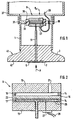
- Fig. 1 is a section through a pressure sensor according to the invention shown.
- the pressure sensor comprises a substantially cylindrical housing 1, in whose one end a diaphragm seal 3 is enclosed. It is welded into the housing 1.
- the pressure transmitter 3 has a chamber 5 filled with a liquid, which is closed by a separating membrane 7.
- a pressure P to be measured acts on the separation membrane 7, which in Fig. 1 indicated by an arrow.
- a ceramic measuring cell 9 is arranged, which is connected via a filled with the liquid tube 11 with the chamber 5 of the pressure transmitter 3.
- Fig. 2 It shows an enlarged view of the measuring cell 9. It comprises two cylindrical body 13 and a rimmed between the two bodies measuring diaphragm 15th
- the measuring cell 9 is a ceramic measuring cell, i. the main body 13 and the measuring diaphragm 15 are made of ceramic.
- the measuring diaphragm 15 is pressure-tight and gas-tight with each of the base body 1 at the edge facing the respective base body 13 by means of a joint 14.
- As the joining material e.g. an active hard solder.
- the measuring diaphragm 15 is pressure-sensitive, i. a pressure acting on them causes a deflection of the measuring diaphragm 15 from its rest position.
- the ceramic measuring cell 9 is connected to the diaphragm seal 3 exclusively with inorganic materials.
- joining or joining techniques such as soldering or welding are suitable.
- the first chamber 17 is connected via the tube 11 with the diaphragm seal 3.
- the tube 11 is welded, for example, to the diaphragm seal 3 and fixed to the base body 13 by a soldering. No gasket made of organic material is required.
- the first chamber 17 is just like the diaphragm seal 3 and the tube 11 filled with liquid.
- a pressure P acting on the separating membrane 7 is transmitted through the liquid to the measuring cell 9 in the first chamber 17.
- the liquid is as incompressible as possible and has the lowest possible coefficient of thermal expansion.
- commercially available silicone oils are suitable.
- the required filling amount is preferably to be kept low by the tube 11 has a small diameter and the pressure transmitter 3 in the chamber 5 has a membrane bed, which is modeled after the shape of the separation membrane 7 and is arranged at a small distance from the separation membrane 7.
- a flame arrester can be arranged in the tube 11 or the tube 11 itself can form a flame arrester due to its dimensions.
- the structure of such a flame arrester can be found in the national safety regulations and standards for explosion protection.
- the second chamber 19 an opening 21, here a base body 13 penetrating bore, through which a reference pressure is introduced into the second chamber 19.
- the reference pressure is a pressure prevailing in the pressure sensor reference pressure P R , here an ambient pressure. It is therefore a relative pressure sensor.
- a variable pressure e.g. be introduced into the second chamber 19 via a second in a similar manner to the pressure transmitter 3 connected to the pressure transmitter.
- the deflection of the measuring diaphragm is dependent on the difference between the two pressures acting on it.
- the pressure sensor according to the invention can of course also be designed as an absolute pressure sensor.
- the second chamber 19 is evacuated and hermetic sealed and the reference pressure is a prevailing in the second chamber 19 absolute pressure.
- the measuring cell 9 has an electromechanical transducer for detecting a dependent of the pressure P and the reference pressure deflection of the diaphragm 15 and for converting them into an electrical output signal.
- the electromechanical transducer comprises a capacitor which has a arranged in the first chamber 17 on the measuring diaphragm 15 measuring electrode 23 and the one of the measuring electrode 23 opposite on an inner wall of the first chamber 17 arranged on the base body 13 counter electrode 25.
- the capacitance of the capacitor depends on the distance of the measuring electrode 23 and the counter electrode 25 to each other and is thus a measure of the deflection of the measuring diaphragm 15th
- the measuring electrode 23 is electrically contacted by the joint 14 and outside of e.g. connected to ground.
- the counterelectrode 25 is electrically contacted by the base body 13 to the outside thereof and leads to an electronic circuit 27 arranged on the base body 13. Measuring electrode 23 and counter electrode 25 form a capacitor and the electronic circuit 27 forms the capacitance changes of the capacitor e.g. in a correspondingly changing electrical voltage.
- the output signal is available via connecting lines 29 for further processing and / or evaluation.
- the pressure sensor is to be used at very high temperatures, it is advisable to arrange the electronic circuit 27 at some distance from the pressure transmitter 3 and the ceramic measuring cell 9.
- Electrodes may be arranged in the first chamber 17 on the base body 13 and / or on the measuring diaphragm 15. It could, for example, instead of the Counter electrode 25 may be provided a circular disk-shaped inner electrode and a surrounding outer annular disc-shaped electrode. It would form the outer electrode together with the measuring electrode 23, a second capacitor whose capacity can serve for compensation purposes, while the inner electrode together with the measuring electrode 23 has a pressure and the reference pressure dependent capacity.
- piezoresistive elements or strain gauges are used as an electromechanical transducer but also arranged on the measuring diaphragm 15 in the first chamber 17 piezoresistive elements or strain gauges.
- a major advantage of the above-described pressure sensor in the training as a relative pressure sensor is that the electromechanical transducer is completely protected from moisture, for example, by condensate, and contaminants. Moisture and / or contaminants typically contained in the atmosphere in the pressure sensor may be deposited only in the second chamber 19. By contrast, the first chamber 17, which contains the electromechanical transducer sensitive to moisture and / or impurities, is closed to the environment.
- the measuring cell 9 is fixed in the housing 1 by being seated in the axial direction on the tube 11, via which the ceramic measuring cell 9 is connected to the diaphragm seal 3. In addition, it is enclosed in a radial direction in a holder.
- a pressure-resistant clamping, as required in conventional ceramic pressure measuring cells is not necessary in the pressure sensor according to the invention, since the pressure P is introduced through the diaphragm seal in the first chamber 17 and thus on the thin tube 11 only a very small force on the measuring cell 9 exercises as a whole.
- a clamping generally exerts a, in particular. Pressure- and temperature-dependent, reaction to the measuring cell. This can lead to a change of sensor data of the pressure sensor, eg its zero point or its temperature characteristic data, and thus to measurement errors, especially if the clamping acts back on the measuring diaphragm.
- the measuring accuracy of ceramic measuring cells which in any case is very stable over a long period of time compared to other measuring cells, is further improved.
- a radially inwardly extending shoulder 31 is formed on the housing 1 at the level of the measuring cell 9, on the inner circumferential surface of an annular circumferential spring 33 is arranged.
- An existing between the housing 1 and measuring cell 9 space is filled by a body 35 made of an elastomer.
- the body 35 has an outer annular circumferential groove into which the spring 33 of the shoulder 31 loosely engages.
- the body 35 surrounds the measuring cell 9 and prevents a deflection of the seated on the tube 11 measuring cell 9 in the radial direction. In the axial direction, however, the measuring cell 9 is movable to compensate for thermal expansion differences can.
- a terminal housing 37 To the housing 1 closes in the direction of the pressure transmitter facing away from a terminal housing 37.
- the terminal housing 37 is screwed onto the housing 1.
- further electronics in which the measurement signals are processed.
- the shoulder 31 has laterally a bore 39 through which the leads 29 are guided. About the leads 29, the measurement signals of further processing and / or evaluation are accessible.
- the process connection 41 serves to fix the pressure sensor at a measuring location.
- the process connection 41 is a standard connection as defined in international standard ISO 2852. This connection is known in metrology under the trade name 'Triclamp'. Other types of attachment are also applicable.
- the separation membrane 7 is flush with the front of the process connection 41 and forms a pressure and gas-tight seal against the process. Other types of attachment, e.g. by means of a flange or screw, are also used.
- a prevailing at the measuring pressure P acts directly on the separation membrane 7 and is transmitted via the pressure transmitter 3 and the liquid in the tube 11 in the measuring cell 9.
- the separation membrane 7 and all others with a medium whose pressure is to be measured when measuring sensor components coming into contact, in the embodiment shown, the process connection 41, are metallic.
- Metal offers the great advantage that such a sensor can be installed flush with the front and thus easy to clean.
- the pressure sensor according to the invention has the advantage that the pressure sensor itself completely manages without coming into contact with the medium of the gasket. It is only a single seal, namely a process seal for sealing the measuring site from the environment required.
- the process connection 41 has an annular circumferential groove 42 for receiving this, in Fig. 1 not shown, process seal on.
- the process seal can be easily replaced at any time and replacement of the process seal has no effect on the accuracy of the pressure sensor.
- the pressure sensor of the invention it is possible to use the pressure sensor of the invention directly in a so-called weld neck, i. to be mounted on the container welded nozzle.
- the sealing takes place in weld-in sockets usually purely metallic, e.g. about sealing koni.
- This offers compared to the illustrated process connection 41 has the advantage that the pressure sensor is not only flush-mounted, but also entirely without seals, even without process seal, gets along.
- the pressure sensor is therefore very well suited for applications in the food industry, where the demands for cleanability, freedom from gaskets and metallic materials are particularly important.
- measuring cell 9 is a Relativdruckmeßzelle. It is the measured pressure P relative to the reference pressure detected, wherein the reference pressure is here the variable ambient pressure. It can be constructed in a completely analogous manner to the above-described relative pressure sensor and an absolute pressure sensor. In such an absolute pressure sensor eliminates the opening 21, and the second chamber 19 is evacuated. Accordingly, the reference pressure is then the fixed vacuum pressure in the second chamber.
Landscapes
- Chemical & Material Sciences (AREA)
- Engineering & Computer Science (AREA)
- Ceramic Engineering (AREA)
- Physics & Mathematics (AREA)
- General Physics & Mathematics (AREA)
- Measuring Fluid Pressure (AREA)
Description
Die Erfindung betrifft einen Drucksensor.The invention relates to a pressure sensor.
In der Druckmeßtechnik werden z.B. Absolut- und Relativdrucksensören verwendet. Bei Absolutdrucksensoren wird ein zu messender Druck absolut, d.h. als Druckunterschied gegenüber einem Vakuum erfaßt. Mit einem Relativdrucksensor wird ein zu messender Druck in Form eines Druckunterschiedes gegenüber einem Referenzdruck, z.B. einem Druck, der dort herrscht, wo sich der Sensor befindet, aufgenommen. Bei den meisten Anwendungen ist dies der Atmosphärendruck am Einsatzort. Es wird also beim Absolutdrucksensor ein zu messender Druck bezogen auf einen festen Bezugsdruck, den Vakuumdruck, und beim Relativdrucksensor ein zu messender Druck bezogen auf einen variablen Bezugsdruck, z.B. den Umgebungsdruck, erfaßt.In the pressure measuring technique, e.g. Absolute and relative pressure sensors used. In absolute pressure sensors, a pressure to be measured becomes absolute, i. detected as a pressure difference to a vacuum. With a relative pressure sensor, a pressure to be measured in the form of a pressure difference from a reference pressure, e.g. a pressure prevailing where the sensor is located. For most applications, this is atmospheric pressure at the jobsite. Thus, in the case of the absolute pressure sensor, a pressure to be measured relative to a fixed reference pressure, the vacuum pressure, and in the case of the relative pressure sensor, a pressure to be measured relative to a variable reference pressure, e.g. the ambient pressure detected.
Es werden in der Druckmeßtechnik vorteilhaft keramische Druckmeßzellen eingesetzt, da keramische Druckmeßzellen eine Meßgenauigkeit aufweisen, die über sehr lange Zeit stabil ist. Ein Grund hierfür ist die feste ionische Bindung von Keramik, durch die der Werkstoff sehr dauerhaft ist und im Vergleich zu anderen Werkstoffen, z.B. Metallen, praktisch nicht altert. Keramische Drucksensoren weisen jedoch eine im Vergleich zu einem Metall rauhere Oberfläche auf und sind regelmäßig mittels einer in der Regel nicht auswechselbaren Dichtung aus einem organischen Material, z.B. einem Elastomer, druckfest in ein Gehäuse eingespannt, das dann über einen Prozeßanschluß an einem Meßort zu befestigen ist.It can be used in the pressure measuring advantageous ceramic pressure measuring cells, since ceramic pressure measuring cells have a measurement accuracy that is stable over a very long time. One reason for this is solid ionic bonding of ceramics, which makes the material very durable and, compared to other materials, e.g. Metals, practically not aging. However, ceramic pressure sensors have a rougher surface compared to a metal and are periodically replaced by a generally non-replaceable gasket made of an organic material, e.g. an elastomer, pressure-tight clamped in a housing, which is then to be attached via a process connection to a measuring location.
In der Lebensmittelindustrie werden bevorzugt frontbündig einbaubare Drucksensoren eingesetzt, bei denen alle mit einem Medium, dessen Druck es zu messen gilt, in Berührung kommenden Sensorelemente aus einem Metall, vorzugsweise aus einem sehr gut reinigbaren Edelstahl, bestehen.In the food industry, preference is given to using front-mounted pressure sensors, all of which are in contact with a medium whose pressure is to be measured coming sensor elements made of a metal, preferably from a very cleanable stainless steel, exist.
In diesem Industriezweig ist es zusätzlich von besonderem Vorteil, wenn die Drucksensoren möglichst wenig Dichtungen aufweisen. Dichtungen bestehen aus organischen Materialien und sollten daher aus hygienischen Gründen vorzugsweise austauschbar sein. Im Idealfall ist nur eine einzige Dichtung zur Abdichtung des Prozeßanschlusses vorhanden. Diese, nachfolgend als Prozeßdichtung bezeichnete Dichtung, kann im Gegensatz zu einer zum Sensor gehörigen Dichtung vom Anwender selbst jederzeit problemlos, insb. ohne Auswirkung auf die Meßgenauigkeit des Drucksensors, ausgetauscht werden.In this industry, it is additionally particularly advantageous if the pressure sensors have as few seals as possible. Seals are made of organic materials and should therefore preferably be interchangeable for hygienic reasons. Ideally, there is only a single seal to seal the process connection. This, hereinafter referred to as process seal seal, in contrast to a sensor associated with the seal itself at any time easily, esp. Without effect on the accuracy of the pressure sensor to be replaced.
Es ist eine Aufgabe der Erfindung, einen unter anderem für die Lebensmittelindustrie geeigneten Drucksensor anzugeben, dessen Meßgenauigkeit über lange Zeit stabil ist.It is an object of the invention to provide a pressure sensor which is suitable, inter alia, for the food industry and whose measuring accuracy is stable for a long time.
Die Aufgabe wird gelöst durch den Drucksensor gemäß Anspruch 1.The object is achieved by the pressure sensor according to
Erfindungsgemäß ist die Meßzelle in einem Gehäuse einspannungsfrei fixiert, indem sie in axialer Richtung auf einem Röhrchen aufsitzt, über das die keramische Meßzelle mit dem Druckmittler verbunden ist.According to the invention, the measuring cell is fixed in a housing without tension by being seated in the axial direction on a tube, via which the ceramic measuring cell is connected to the pressure transmitter.
Erfindungsgemäß weist die Meßzelle eine Meßmembran auf, die einen Innenraum der Meßzelle in eine erste und eine zweite Kammer unterteilt. Die erste Kammer ist über ein Röhrchen mit dem Druckmittler verbunden, die erste Kammer, das Röhrchen und der Druckmittler sind mit einer Flüssigkeit gefüllt, die Flüssigkeit überträgt einen auf die Trennmembran einwirkenden Druck auf die Meßmembran, in der zweiten Kammer wirkt ein Bezugsdruck auf die Meßmembran ein, und der Drucksensor weist einen elektromechanischen Wandler zur Erfassung einer vom Druck und vom Bezugsdruck abhängigen Auslenkung der Meßmembran und zu deren Umwandlung in ein elektrisches Ausgangssignal auf.According to the invention, the measuring cell to a measuring diaphragm, which is an interior of the measuring cell in a divided into a first and a second chamber. The first chamber is connected via a tube to the diaphragm seal, the first chamber, the tube and the diaphragm seal are filled with a liquid, the liquid transmits a pressure acting on the separation membrane pressure on the measuring diaphragm, in the second chamber, a reference pressure acts on the measuring diaphragm a, and the pressure sensor comprises an electromechanical transducer for detecting a pressure and the reference pressure dependent deflection of the diaphragm and for converting them into an electrical output signal.
Erfindungsgemäß ist der Bezugsdruck ein in der Umgebung herrschender Referenzdruck und die zweite Kammer weist eine Öffnung auf, durch die der Referenzdruck in die zweite Kammer eingeleitet ist, oder die zweite Kammer ist hermetisch dicht verschlossen und der Bezugsdruck ist ein in der zweiten Kammer herrschender Absolutdruck.According to the invention, the reference pressure is a reference pressure prevailing in the environment and the second chamber has an opening through which the reference pressure is introduced into the second chamber, or the second chamber is hermetically sealed and the reference pressure is an absolute pressure prevailing in the second chamber.
Gemäß einer Ausgestaltung ist die Meßzelle zusätzlich in radialer Richtung in eine Halterung eingefaßt.According to one embodiment, the measuring cell is additionally enclosed in the radial direction in a holder.
Gemäß einer Ausgestaltung weist die Halterung einen einen Zwischenraum zwischen der Meßzelle und dem Gehäuse ausfüllenden Körper aus einem Elastomer auf. Untersuchungen haben gezeigt, daß bei einer auf herkömmliche Weise mittels eines organischen Werkstoffes, z.B. einer Dichtung aus einem Elastomer, druckfest eingespannten keramischen Meßzelle Druckmittler nicht ohne sehr große Einbußen in der Meßgenauigkeit einsetzbar sind. Durch Temperatur- und/oder Druckwechsel kann es zu Lage- und/oder Formveränderungen der Dichtung kommen, die mit einer Verschiebung von Druckmittlerflüssigkeit verbunden sind. Bei einem Druckmittler wird durch eine Druckänderung nur eine geringe Menge der Druckmittlerflüssigkeit verschoben. Liegen dichtungs-bedingte Volumenverschiebunge in der gleichen Größenordnung wie druck-bedingte Volumenverschiebungen, so ist eine sinnvolle Messung nicht mehr möglich.According to one embodiment, the holder has a body filling an intermediate space between the measuring cell and the housing made of an elastomer. Investigations have shown that in a conventional manner by means of an organic material, such as a seal made of an elastomer, pressure-tight clamped ceramic measuring cell diaphragm seals can not be used without very large losses in the accuracy of measurement. Temperature and / or pressure changes can lead to changes in position and / or shape of the seal, which are associated with a displacement of diaphragm seal fluid. In a diaphragm seal, only a small amount of the diaphragm seal fluid is displaced by a pressure change. If gasket-related volume shifts are of the same order of magnitude as pressure-related volume shifts, a meaningful measurement is no longer possible.
Üblicherweise verwendete Dichtungsmaterialien sind Kunststoffe wie z.B. Polytetrafluorethylen oder Viton. Diese Werkstoffe sind nicht gasdicht. Wenn auf den Drucksensor ein Unterdruck einwirkt, kann durch die Dichtung Luft oder Gas von einer druckmittler-abgewandten Seite des Drucksensors in die Druckmittlerflüssigkeit eindiffundieren. Luft oder Gas in derCommonly used sealing materials are plastics such as e.g. Polytetrafluoroethylene or Viton. These materials are not gas-tight. If a vacuum acts on the pressure sensor, air or gas can diffuse into the diaphragm seal fluid through the seal from a side of the pressure sensor facing away from the pressure transmitter. Air or gas in the
Druckmittlerflüssigkeit beeinträchtigt die Meßgenauigkeit des Drucksensor stark.Diaphragm seal seriously affects the accuracy of the pressure sensor.
Aufgrund des erfindungsgemäßen Anschlusses des Druckmittlers mittels Verbindungen aus anorganischen Materialien kann vollständig auf Dichtungen verzichtet werden. Es ist damit erstmals möglich, eine keramische Druckmeßzelle in Verbindung mit einem Druckmittler einzusetzen und die Vorteile der keramischen Meßzellen, nämlich deren über sehr lange Zeit stabile Meßgenauigkeit in Verbindung mit einem Druckmittler auszunutzen.Due to the inventive connection of the diaphragm seal by means of compounds of inorganic materials can be completely dispensed with seals. It is thus possible for the first time to use a ceramic pressure measuring cell in conjunction with a pressure transmitter and the advantages of the ceramic measuring cells, namely to exploit their over a very long time stable measurement accuracy in conjunction with a diaphragm seal.
Mechanische Verbindungen bzw. Anschlüsse aus anorganischen Materialien können z.B. Schweißungen oder Lötungen, insb. Aktivhartlötungen, sein. Solche metallischen Fügungen bieten den Vorteil, daß sie gasdicht und im Vergleich zu Anschlußweisen mittels organischen Materialien, wie z.B. mittels eingespannten Dichtungen, mechanisch unbeweglich und weitestgehend kriechfrei sind. Über Druck- und/oder Temperaturwechsel tritt somit bei einem erfindungsgemäßen Drucksensor keine bleibende Verformung der Verbindungsmaterialien an den Anschlußstellen auf, die zu einer Verschlechterung der Meßgenauigkeit führen könnte. Die Meßgenauigkeit der erfindungsgemäßen Drucksensoren kann daher über sehr lange Zeiträume garantiert werden.Mechanical connections of inorganic materials may e.g. Welding or soldering, esp. Aktivhartlötungen be. Such metallic joints offer the advantage of being gas-tight and, compared to connections by means of organic materials, e.g. by means of clamped seals, mechanically immobile and largely free of creep. About pressure and / or temperature change thus occurs in a pressure sensor according to the invention no permanent deformation of the connecting materials at the connection points, which could lead to a deterioration of the measurement accuracy. The measurement accuracy of the pressure sensors according to the invention can therefore be guaranteed over very long periods.
Ein weiterer Vorteil besteht darin, daß trotz der Verwendung einer keramischen Druckmeßzelle, abgesehen von der Prozeßdichtung, nur metallische Materialien mit dem Medium, dessen Druck es zu messen gilt, in Berührung kommen. Durch die Verwendung des Druckmittlers ist es möglich das von dem Medium berührte Metall innerhalb weiter Grenzen frei entsprechend den mechanischen und/oder chemischen Eigenschaften des Mediums auszuwählen.Another advantage is that, despite the use of a ceramic pressure measuring cell, apart from the process seal, only metallic materials come into contact with the medium whose pressure is to be measured. By using the pressure transmitter, it is possible to freely select the metal touched by the medium within wide limits according to the mechanical and / or chemical properties of the medium.
Es gibt auch Anwendungen, bei denen der Druckmittler direkt am Meßort in einem sogenannten Einschweißstutzen, d.h. einem auf dem Behälter aufgeschweißten Stutzen, montiert werden. Die Abdichtung erfolgt in Einschweißstutzen üblicherweise rein metallisch, z.B. über Dichtkoni. In diesen Fällen entfällt sogar die Prozeßdichtung.There are also applications in which the diaphragm seal is located directly at the measurement location in a so-called weld neck, i. mounted on the container welded neck. The sealing takes place in weld-in sockets usually purely metallic, e.g. about sealing koni. In these cases, even the process seal is eliminated.
Die Erfindung und weitere Vorteile werden nun anhand der Figuren der Zeichnung, in denen ein Ausführungsbeispiel dargestellt ist, näher erläutert. Gleiche Elemente sind in den Figuren mit den gleichen Bezugszeichen versehen.
- Fig. 1
- zeigt einen Schnitt durch einen erfindungsgemäßen Drucksensor, bei dem eine keramische Meßzelle auf einem Röhrchen fixiert ist, mittels dem sie mit einem Druckmittler verbunden ist; und
- Fig. 2
- zeigt eine vergrößerte Darstellung der Meßzelle von
Fig. 1 ;
- Fig. 1
- shows a section through a pressure sensor according to the invention, in which a ceramic measuring cell is fixed on a tube, by means of which it is connected to a pressure transmitter; and
- Fig. 2
- shows an enlarged view of the measuring cell of
Fig. 1 ;
In
In dem Gehäuse 1 ist eine keramische Meßzelle 9 angeordnet, die über ein mit der Flüssigkeit gefülltes Röhrchen 11 mit der Kammer 5 des Druckmittlers 3 verbunden ist.In the
Die Meßzelle 9 ist eine keramische Meßzelle, d.h. die Grundkörper 13 und die Meßmembran 15 bestehen aus Keramik. Die Meßmembran 15 ist mit jedem der Grundkörper 1 an deren dem jeweiligen Grundkörper 13 zugewandten Rand mittels einer Fügestelle 14 druckdicht und gasdicht verbunden. Als Fügematerial eignet sich z.B. ein Aktivhartlot. Die Meßmembran 15 ist druckempfindlich, d.h. ein auf sie einwirkender Druck bewirkt eine Auslenkung der Meßmembran 15 aus deren Ruhelage.The
Durch die Meßmembran 15 und die Fügestellen 14 ist ein Innenraum der Meßzelle 9 in eine erste Kammer 17 und eine zweite Kammer 19 unterteilt. Die keramische Meßzelle 9 ist an den Druckmittler 3 ausschließlich mit anorganischen Materialien angeschlossen. Hierzu eignen sich z.B. Verbindungs- bzw. Fügetechniken wie Löten oder Schweißen. In dem in
Die erste Kammer 17 ist genauso wie der Druckmittler 3 und das Röhrchen 11 mit Flüssigkeit gefüllt. Ein auf die Trennmembran 7 einwirkender Druck P wird durch die Flüssigkeit auf die Meßzelle 9 in die erste Kammer 17 übertragen. Die Flüssigkeit ist möglichst inkompressibel und weist einen möglichst geringen thermischen Ausdehnungskoeffizienten auf. Es eignen sich z.B. im Handel erhältliche Silikonöle. Zusätzlich ist die erforderliche Füllmenge vorzugsweise gering zu halten, indem das Röhrchen 11 einen geringen Durchmesser aufweist und der Druckmittler 3 in der Kammer 5 ein Membranbett aufweist, das der Form der Trennmembran 7 nachempfunden ist und in geringem Abstand von der Trennmembran 7 angeordnet ist.The first chamber 17 is just like the diaphragm seal 3 and the
Für den Fall, daß der Drucksensor in explosionsgefährdeten Bereichen eingesetzt werden soll, kann in dem Röhrchen 11 eine Flammendurchschlagsperre angeordnet sein oder das Röhrchen 11 selbst kann aufgrund dessen Abmessungen eine Flammendurchschlagsperre bilden. Der Aufbau einer solchen Flammendurchschlagsperre ist den nationalen Sicherheitsvorschriften und Normen zum Explosionsschutz entnehmbar.In the event that the pressure sensor is to be used in potentially explosive areas, a flame arrester can be arranged in the
In dem in
Es kann anstelle des Umgebungsdrucks auch ein variabler Druck, z.B. über einen zweiten auf analoge Weise zu dem Druckmittler 3 angeschlossenen Druckmittler, in die zweite Kammer 19 eingeleitet sein. In diesem Fall ist die Auslenkung der Meßmembran abhängig von der Differenz der beiden auf sie einwirkenden Drücke.Instead of the ambient pressure, a variable pressure, e.g. be introduced into the
Der erfindungsgemäße Drucksensor kann selbstverständlich auch als Absolutdrucksensor ausgebildet sein. In diesem Fall ist die zweite Kammer 19 evakuiert und hermetisch dicht verschlossen und der Bezugsdruck ist ein in der zweiten Kammer 19 herrschender Absolutdruck.The pressure sensor according to the invention can of course also be designed as an absolute pressure sensor. In this case, the
Die Meßzelle 9 weist einen elektromechanischen Wandler zur Erfassung einer vom Druck P und vom Bezugsdruck abhängigen Auslenkung der Meßmembran 15 und zu deren Umwandlung in ein elektrisches Ausgangssignal auf.The measuring
In dem in
Die Meßelektrode 23 ist durch die Fügestelle 14 hindurch elektrisch kontaktiert und außerhalb z.B. mit Masse verbunden. Die Gegenelektrode 25 ist durch den Grundkörper 13 hindurch zu dessen Außenseite hin elektrisch kontaktiert und führt zu einer auf dem Grundkörper 13 angeordneten elektronischen Schaltung 27. Meßelektrode 23 und Gegenelektrode 25 bilden einen Kondensator und die elektronische Schaltung 27 formt die Kapazitätsänderungen des Kondensators z.B. in eine sich entsprechend ändernde elektrische Spannung um.The measuring
Das Ausgangssignal steht über Anschlußleitungen 29 einer weiteren Verarbeitung und/oder Auswertung zur Verfügung.The output signal is available via connecting
Wenn der Drucksensor bei sehr hohen Temperaturen eingesetzt werden soll, empfiehlt es sich die elektronische Schaltung 27 in einiger Entfernung vom Druckmittler 3 und der keramischen Meßzelle 9 anzuordnen.If the pressure sensor is to be used at very high temperatures, it is advisable to arrange the
Selbstverständlich können auch mehr Elektroden in der ersten Kammer 17 auf dem Grundkörper 13 und/oder auf der Meßmembran 15 angeordnet sein. Es könnte z.B. statt der Gegenelektrode 25 eine kreisscheibenförmige innere Elektrode und eine diese umgebende äußere ringscheibenförmige Elektrode vorgesehen sein. Es würde die äußere Elektrode zusammen mit der Meßelektrode 23 einen zweiten Kondensator bilden, dessen Kapazität zu Kompensationszwecken dienen kann, während die innere Elektrode zusammen mit der Meßelektrode 23 eine vom Druck und vom Bezugsdruck abhängige Kapazität aufweist.Of course, more electrodes may be arranged in the first chamber 17 on the
Als elektromechanische Wandler sind aber auch auf der Meßmembran 15 in der ersten Kammer 17 angeordnete piezoresistive Elemente oder Dehnungsmeßstreifen einsetzbar.As an electromechanical transducer but also arranged on the measuring
Ein großer Vorteil des vorbeschriebenen Drucksensors in der ausbildung als Relativdrucksensor ist, daß der elektromechanische Wandler vollständig vor Feuchtigkeit, z.B, durch Kondensat, und Verunreinigungen geschützt ist. Feuchtigkeit und/oder Verunreinigungen, wie sie typischerweise in der Atmosphäre in dem Drucksensor enthalten sind können sich ausschließlich in der zweiten Kammer 19 ablagern. Die erste Kammer 17, die den gegenüber Feuchtigkeit und/oder Verunreinigungen empfindlichen elektromechanischen Wandler enthält ist dagegen gegenüber der Umwelt verschlossen.A major advantage of the above-described pressure sensor in the training as a relative pressure sensor is that the electromechanical transducer is completely protected from moisture, for example, by condensate, and contaminants. Moisture and / or contaminants typically contained in the atmosphere in the pressure sensor may be deposited only in the
Die Meßzelle 9 ist in dem Gehäuse 1 fixiert, indem sie in axialer Richtung auf dem Röhrchen 11, über das die keramische Meßzelle 9 mit dem Druckmittler 3 verbunden ist, aufsitzt. Zusätzlich ist sie in radialer Richtung in eine Halterung eingefaßt. Eine druckfeste Einspannung, wie sie bei herkömmlichen keramischen Druckmeßzellen erforderlich ist, ist bei dem erfindungsgemäßen Drucksensor nicht nötig, da der Druck P durch den Druckmittler in die erste Kammer 17 eingeleitet ist und somit über das dünne Röhrchen 11 nur eine sehr geringe Kraft auf die Meßzelle 9 als Ganzes ausübt. Eine Einspannung übt generell eine, insb. druck- und temperatur-abhängige, Rückwirkung auf die Meßzelle aus. Dies kann, besonders wenn die Einspannung auf die Meßmembran zurückwirkt, zu einer Veränderung von Sensordaten des Drucksensors, z.B. dessen Nullpunkt oder dessen Temperaturkenndaten, und damit zu Meßfehlern führen.The measuring
Durch die einspannungsfreie Montage der keramischen Meßzelle 9 ist die ohnehin im Vergleich zu anderen Meßzellen über lange Zeit sehr stabile Meßgenauigkeit von keramischen Meßzellen noch weiter verbessert.As a result of the non-tension-free mounting of the ceramic measuring
Bei dem in
An das Gehäuse 1 schließt in druckmittler-abgewandter Richtung ein Anschlußgehäuse 37 an. In dem gezeigten Ausführungsbeispiel ist das Anschlußgehäuse 37 auf das Gehäuse 1 aufgeschraubt. In dem Anschlußgehäuse 37 ist beispielsweise eine, in
Auf einer von der Meßzelle 9 abgewandten Seite ist der Druckmittler 3 als ein Prozeßanschluß 41 ausgebildet. Der Prozeßanschluß 41 dient dazu, den Drucksensor an einem Meßort zu befestigen. In dem gezeigten Ausführungsbeispiel ist der Prozeßanschluß 41 ein Standardanschluß, wie er in der internationalen Norm ISO 2852 definiert ist. Dieser Anschluß ist in der Meßtechnik unter dem Handelsnamen 'Triclamp' bekannt. Andere Arten der Befestigung sind ebenfalls einsetzbar. Die Trennmembran 7 schließt frontbündig mit dem Prozeßanschluß 41 ab und bildet einen druck- und gasdichten Abschluß gegenüber dem Prozeß. Andere Arten der Befestigung, z.B. mittels einer Flansch- oder Schraubverbindung, sind ebenfalls einsetzbar.On a side facing away from the measuring
Ein am Meßort herrschender Druck P wirkt direkt auf die Trennmembran 7 ein und wird über den Druckmittler 3 und die Flüssigkeit im Röhrchen 11 in die Meßzelle 9 übertragen.A prevailing at the measuring pressure P acts directly on the separation membrane 7 and is transmitted via the pressure transmitter 3 and the liquid in the
Die Trennmembran 7 und alle weiteren mit einem Medium, dessen Druck zu messen ist, beim Messen in Kontakt kommenden Sensorbauteile, in dem gezeigten Ausführungsbeispiel der Prozeßanschluß 41, sind metallisch.The separation membrane 7 and all others with a medium whose pressure is to be measured when measuring sensor components coming into contact, in the embodiment shown, the
Metall bietet hier den großen Vorteil, daß ein solcher Sensor frontbündig einbaubar und somit gut zu reinigen ist.Metal offers the great advantage that such a sensor can be installed flush with the front and thus easy to clean.
Der erfindungsgemäße Drucksensor bietet den Vorteil, daß der Drucksensor selbst völlig ohne eine mit dem Medium in Berührung kommende Dichtung auskommt. Es ist lediglich eine einzige Dichtung, nämlich eine Prozeßdichtung zur Abdichtung des Meßortes gegenüber der Umgebung, erforderlich. Der Prozeßanschluß 41 weist eine ringförmig umlaufende Nut 42 zur Aufnahme dieser, in
In einigen Anwendungen ist es möglich den erfindungsgemäßen Drucksensor direkt in einem sogenannten Einschweißstutzen, d.h. einem auf dem Behälter aufgeschweißten Stutzen, zu montieren. Die Abdichtung erfolgt in Einschweißstutzen üblicherweise rein metallisch, z.B. über Dichtkoni. Dies bietet gegenüber dem dargestellten Prozeßanschluß 41 den Vorteil, daß der Drucksensor nicht nur frontbündig angeordnet ist, sondern auch gänzlich ohne Dichtungen, auch ohne Prozeßdichtung, auskommt.In some applications, it is possible to use the pressure sensor of the invention directly in a so-called weld neck, i. to be mounted on the container welded nozzle. The sealing takes place in weld-in sockets usually purely metallic, e.g. about sealing koni. This offers compared to the illustrated
Der Drucksensor ist daher sehr gut für Anwendungen in der Lebensmittelindustrie geeignet, wo die Forderungen nach Reinigbarkeit, Dichtungsfreiheit und nach metallischen Werkstoffen besonders hohen Stellenwert haben.The pressure sensor is therefore very well suited for applications in the food industry, where the demands for cleanability, freedom from gaskets and metallic materials are particularly important.
Bei der in den
Claims (3)
- Pressure sensor with- a diaphragm seal (3, 45) with a process isolating diaphragm (7, 53)-- on which a pressure (P), which has to be measured, acts and- a ceramic measuring cell (9, 57) which is connected to the diaphragm seal (3, 45) exclusively with inorganic materials- where the process isolating diaphragm (7, 53) is metal, as are all the other sensor components that come in contact, during the measurement process, with a medium whose pressure (P) is to be measured, where the measuring cell (9) is fixed without restraint in a housing (1) by resting in the axial direction on a pipe (11) via which the ceramic measuring cell (9) is connected to the diaphragm seal- where the measuring cell (9) has a measuring diaphragm (15)-- which divides the inside of the measuring cell (9) into a first and second chamber (17, 19), where the first chamber (17) is connected to the diaphragm seal (3) via the pipe (11)- characterized in that the first chamber (17), the pipe (11) and the diaphragm seal (11) are filled with a liquid- characterized in that the liquid transmits a pressure (P), which acts on the process isolating diaphragm (7), to the measuring diaphragm (15)- characterized in that a reference pressure acts on the measuring membrane (15) in the second chamber (19) and- which has an electromechanical converter for recording a deflection of the measuring membrane, which depends on the pressure (P) and the reference pressure, and for converting this to an electric output signal, and where- the reference pressure is a reference pressure present in the surrounding environment, and the second chamber (19) has an opening (21) through which the reference pressure is routed into the second chamber (19), or the second chamber is hermetically sealed and the reference pressure is an absolute pressure present in the second chamber.
- Pressure sensor as per Claim 1, where the measuring cell (9) is also held in a bracket in the radial direction.
- Pressure sensor as per Claim 2, where the bracket has an elastomer body (35) which fills an intermediate chamber between the measuring cell (9) and the housing (1).
Priority Applications (6)
| Application Number | Priority Date | Filing Date | Title |
|---|---|---|---|
| DE50016091T DE50016091D1 (en) | 2000-02-22 | 2000-02-22 | pressure sensor |
| EP00103681A EP1128172B1 (en) | 2000-02-22 | 2000-02-22 | Pressure sensor |
| CA002325903A CA2325903C (en) | 2000-02-22 | 2000-11-15 | Pressure sensor |
| US09/734,739 US6715356B2 (en) | 2000-02-22 | 2000-12-13 | Pressure sensor having metallic diaphragm seal mount |
| JP2001044120A JP3431606B2 (en) | 2000-02-22 | 2001-02-20 | Pressure sensor |
| US10/762,287 US6848318B2 (en) | 2000-02-22 | 2004-01-23 | Pressure sensor having metallic diaphragm seal joint |
Applications Claiming Priority (1)
| Application Number | Priority Date | Filing Date | Title |
|---|---|---|---|
| EP00103681A EP1128172B1 (en) | 2000-02-22 | 2000-02-22 | Pressure sensor |
Publications (2)
| Publication Number | Publication Date |
|---|---|
| EP1128172A1 EP1128172A1 (en) | 2001-08-29 |
| EP1128172B1 true EP1128172B1 (en) | 2011-04-06 |
Family
ID=8167923
Family Applications (1)
| Application Number | Title | Priority Date | Filing Date |
|---|---|---|---|
| EP00103681A Expired - Lifetime EP1128172B1 (en) | 2000-02-22 | 2000-02-22 | Pressure sensor |
Country Status (5)
| Country | Link |
|---|---|
| US (2) | US6715356B2 (en) |
| EP (1) | EP1128172B1 (en) |
| JP (1) | JP3431606B2 (en) |
| CA (1) | CA2325903C (en) |
| DE (1) | DE50016091D1 (en) |
Cited By (2)
| Publication number | Priority date | Publication date | Assignee | Title |
|---|---|---|---|---|
| DE102012103585A1 (en) | 2012-04-24 | 2013-10-24 | Endress + Hauser Gmbh + Co. Kg | pressure transducers |
| DE102014119407A1 (en) | 2014-12-22 | 2016-06-23 | Endress + Hauser Gmbh + Co. Kg | Differential pressure sensor and differential pressure transducer with such a differential pressure sensor |
Families Citing this family (44)
| Publication number | Priority date | Publication date | Assignee | Title |
|---|---|---|---|---|
| DE50016091D1 (en) * | 2000-02-22 | 2011-05-19 | Endress & Hauser Gmbh & Co Kg | pressure sensor |
| DE10039609A1 (en) * | 2000-08-09 | 2002-02-21 | Mannesmann Vdo Ag | pressure sensor |
| US6658940B2 (en) * | 2000-11-15 | 2003-12-09 | Endress + Hauser Gmbh + Co. | Pressure sensor, and a method for mounting it |
| DE10135568A1 (en) * | 2001-07-20 | 2003-02-06 | Endress & Hauser Gmbh & Co Kg | Differential or absolute pressure sensor has a hermetically sealed cap to protect measurement electronics from the external environment and prevent moisture ingress |
| AU2003258296A1 (en) * | 2002-08-19 | 2004-03-03 | Czarnek And Orkin Laboratories, Inc. | Capacitive uterine contraction sensor |
| DE10308820B4 (en) * | 2003-02-27 | 2006-10-12 | Ifm Electronic Gmbh | Sensor, measuring cell for use in a sensor and method for producing a measuring cell |
| DE10314910A1 (en) * | 2003-04-01 | 2004-11-11 | Siemens Ag | pressure sensor |
| DE10319417A1 (en) * | 2003-04-29 | 2004-11-18 | Endress + Hauser Gmbh + Co. Kg | Pressure sensor with temperature compensation |
| EP1491872B1 (en) * | 2003-06-27 | 2005-11-16 | WIKA Alexander Wiegand GmbH & Co.KG | Pressure sensor |
| DE10334854A1 (en) * | 2003-07-29 | 2005-03-10 | Endress & Hauser Gmbh & Co Kg | pressure sensor |
| IL162940A0 (en) * | 2004-07-08 | 2005-11-20 | Yechiel Cohen | Clamping device and dental handpiece including same |
| ITMI20042329A1 (en) * | 2004-12-03 | 2005-03-03 | Elettrotec Srl | ELECTRONIC PRESSURE SWITCH WITH POSSIBILITY OF QUICK SETTING OF THE MAIN OPERATING PARAMETERS |
| DE102005002658A1 (en) * | 2005-01-19 | 2006-07-27 | Endress + Hauser Gmbh + Co. Kg | Hydraulic diaphragm seal and pressure sensor or differential pressure sensor with hydraulic diaphragm seal |
| US7334484B2 (en) | 2005-05-27 | 2008-02-26 | Rosemount Inc. | Line pressure measurement using differential pressure sensor |
| DE102005053062B4 (en) * | 2005-11-04 | 2011-02-10 | Ifm Electronic Gmbh | pressure sensor |
| DE102006049942B4 (en) * | 2006-10-19 | 2013-10-02 | Endress + Hauser Gmbh + Co. Kg | Diaphragm seal, pressure sensor with diaphragm seal and method for producing a diaphragm seal |
| DE102007024270B4 (en) * | 2007-05-23 | 2011-03-17 | Otto Radau | Diaphragm for a diaphragm seal |
| NO326691B1 (en) * | 2007-11-19 | 2009-01-26 | Presens As | Pressure sensor unit |
| DE102008043175A1 (en) * | 2008-10-24 | 2010-04-29 | Endress + Hauser Gmbh + Co. Kg | Relative pressure sensor |
| DE102011004729A1 (en) | 2011-02-25 | 2012-08-30 | Endress + Hauser Gmbh + Co. Kg | Pressure measuring cell of pressure sensor, has lower measuring chamber that communicates with metallic hydraulic line, where upper end portion of hydraulic line is pressure-tightly fastened and welded at casing |
| DE102011102837A1 (en) * | 2011-05-30 | 2012-12-06 | Epcos Ag | Pressure sensor and method for producing a pressure sensor |
| DE102011081887A1 (en) * | 2011-08-31 | 2013-02-28 | Robert Bosch Gmbh | Polymer layer system pressure sensor device and polymer layer system pressure sensor method |
| US8820171B2 (en) * | 2011-09-20 | 2014-09-02 | Corning Incorporated | Method to monitor safe operation of an ultracapacitor |
| DE102011088303A1 (en) | 2011-12-12 | 2013-06-13 | Endress + Hauser Gmbh + Co. Kg | Tubusflanschdruckmittler, pressure measuring arrangement with such a Tubusflanschdruckmittler and pressure measuring point with such a pressure measuring arrangement |
| DE102012110152A1 (en) * | 2012-07-11 | 2014-05-15 | Endress + Hauser Gmbh + Co. Kg | Method for joining ceramic bodies by means of an active brazing alloy, assembly having at least two ceramic bodies joined together, in particular a pressure measuring cell |
| DE102012106236A1 (en) * | 2012-07-11 | 2014-01-16 | Endress + Hauser Gmbh + Co. Kg | Method for joining ceramic bodies by means of an active brazing alloy, assembly having at least two ceramic bodies joined together, in particular a pressure measuring cell |
| EP3598097B8 (en) | 2013-07-19 | 2023-10-11 | Rosemount, Inc. | Pressure transmitter having an isolation assembly with a two-piece isolator plug |
| DE102013217477A1 (en) * | 2013-09-03 | 2015-03-05 | Siemens Aktiengesellschaft | Pressure Transmitter |
| DE102013220735A1 (en) * | 2013-10-14 | 2015-04-16 | Vega Grieshaber Kg | Measuring arrangement with a ceramic measuring cell |
| DE102013114407A1 (en) * | 2013-12-18 | 2015-06-18 | Endress + Hauser Gmbh + Co. Kg | pressure sensor |
| DE102013114608A1 (en) * | 2013-12-20 | 2015-07-09 | Endress + Hauser Gmbh + Co. Kg | Relative pressure sensor |
| DE102014005409A1 (en) * | 2014-04-10 | 2015-10-15 | Wika Alexander Wiegand Se & Co. Kg | Diaphragm seal with adapter |
| DE102015215329A1 (en) * | 2015-08-11 | 2017-02-16 | Continental Automotive Gmbh | Rod-shaped magnetic field sensor |
| DE102015011974A1 (en) * | 2015-09-12 | 2017-03-16 | Hydac Electronic Gmbh | Sensor device, in particular for maritime applications |
| JP6340734B2 (en) * | 2015-09-18 | 2018-06-13 | Smc株式会社 | Pressure sensor |
| DE102016123218A1 (en) * | 2016-12-01 | 2018-06-07 | Endress+Hauser SE+Co. KG | Pressure transducer with a process connection |
| US10627003B2 (en) * | 2017-03-09 | 2020-04-21 | The E3 Company LLC | Valves and control systems for pressure relief |
| DE102017121158B3 (en) | 2017-09-13 | 2019-01-17 | Vega Grieshaber Kg | Diaphragm seal and component arrangement for protecting a pressure transducer before the action of a fluid under a pressure to be measured and method for welding a pressure transducer with a pressure transmitter |
| US20190109656A1 (en) * | 2017-10-10 | 2019-04-11 | Honeywell International Inc. | Passive ultra low frequency target tracker |
| CN209326840U (en) | 2018-12-27 | 2019-08-30 | 热敏碟公司 | Pressure sensor and pressure transmitter |
| CN109946014B (en) * | 2019-03-29 | 2024-05-07 | 江西新力传感科技有限公司 | Miniaturized digital pressure sensor |
| CA3143329A1 (en) * | 2019-06-14 | 2020-12-17 | The E3 Company, Llc | Valves and control systems for pressure equalization and de-energization |
| US11262771B2 (en) * | 2019-09-23 | 2022-03-01 | Rosemount Inc. | High pressure capsule and header for process fluid pressure transmitter |
| DE102022112650A1 (en) | 2022-05-19 | 2023-11-23 | Endress+Hauser SE+Co. KG | Pressure measuring device |
Citations (3)
| Publication number | Priority date | Publication date | Assignee | Title |
|---|---|---|---|---|
| US4501051A (en) * | 1981-05-11 | 1985-02-26 | Combustion Engineering, Inc. | High accuracy differential pressure capacitive transducer and methods for making same |
| DE3820418A1 (en) * | 1987-06-15 | 1988-12-29 | Fischer & Porter Co | DIFFERENTIAL PRESSURE CONVERTER |
| US4798089A (en) * | 1987-03-12 | 1989-01-17 | Rosemount Inc. | Isolator apparatus |
Family Cites Families (9)
| Publication number | Priority date | Publication date | Assignee | Title |
|---|---|---|---|---|
| JPS5516228A (en) * | 1978-07-21 | 1980-02-04 | Hitachi Ltd | Capacity type sensor |
| US4542435A (en) * | 1984-03-29 | 1985-09-17 | General Signal Corporation | Pressure transducer and mounting |
| KR930011091B1 (en) * | 1990-06-08 | 1993-11-20 | 미쯔비시 덴끼 가부시끼가이샤 | Pressure sensor |
| KR0163443B1 (en) * | 1991-07-04 | 1999-03-30 | 나까오 다께시 | Pressure measuring apparatus |
| US5465626A (en) * | 1994-04-04 | 1995-11-14 | Motorola, Inc. | Pressure sensor with stress isolation platform hermetically sealed to protect sensor die |
| US5656780A (en) * | 1996-03-28 | 1997-08-12 | Kavlico Corporation | Capacitive pressure transducer with an integrally formed front housing and flexible diaphragm |
| SE9704840D0 (en) * | 1997-12-22 | 1997-12-22 | Cecap Ab | Pressure sensor for detecting small pressure differences and low pressures |
| US6363790B1 (en) * | 1998-10-23 | 2002-04-02 | Endress + Hauser Gmbh + Co. | Pressure sensor |
| DE50016091D1 (en) * | 2000-02-22 | 2011-05-19 | Endress & Hauser Gmbh & Co Kg | pressure sensor |
-
2000
- 2000-02-22 DE DE50016091T patent/DE50016091D1/en not_active Expired - Lifetime
- 2000-02-22 EP EP00103681A patent/EP1128172B1/en not_active Expired - Lifetime
- 2000-11-15 CA CA002325903A patent/CA2325903C/en not_active Expired - Fee Related
- 2000-12-13 US US09/734,739 patent/US6715356B2/en not_active Expired - Lifetime
-
2001
- 2001-02-20 JP JP2001044120A patent/JP3431606B2/en not_active Expired - Fee Related
-
2004
- 2004-01-23 US US10/762,287 patent/US6848318B2/en not_active Expired - Fee Related
Patent Citations (3)
| Publication number | Priority date | Publication date | Assignee | Title |
|---|---|---|---|---|
| US4501051A (en) * | 1981-05-11 | 1985-02-26 | Combustion Engineering, Inc. | High accuracy differential pressure capacitive transducer and methods for making same |
| US4798089A (en) * | 1987-03-12 | 1989-01-17 | Rosemount Inc. | Isolator apparatus |
| DE3820418A1 (en) * | 1987-06-15 | 1988-12-29 | Fischer & Porter Co | DIFFERENTIAL PRESSURE CONVERTER |
Cited By (5)
| Publication number | Priority date | Publication date | Assignee | Title |
|---|---|---|---|---|
| DE102012103585A1 (en) | 2012-04-24 | 2013-10-24 | Endress + Hauser Gmbh + Co. Kg | pressure transducers |
| WO2013160019A2 (en) | 2012-04-24 | 2013-10-31 | Endress+Hauser Gmbh+Co. Kg | Pressure sensor |
| DE102012103585A8 (en) * | 2012-04-24 | 2014-01-02 | Endress + Hauser Gmbh + Co. Kg | pressure transducers |
| WO2013160019A3 (en) * | 2012-04-24 | 2014-03-20 | Endress+Hauser Gmbh+Co. Kg | Pressure sensor |
| DE102014119407A1 (en) | 2014-12-22 | 2016-06-23 | Endress + Hauser Gmbh + Co. Kg | Differential pressure sensor and differential pressure transducer with such a differential pressure sensor |
Also Published As
| Publication number | Publication date |
|---|---|
| CA2325903A1 (en) | 2001-08-22 |
| JP2001242028A (en) | 2001-09-07 |
| US20040149042A1 (en) | 2004-08-05 |
| EP1128172A1 (en) | 2001-08-29 |
| JP3431606B2 (en) | 2003-07-28 |
| DE50016091D1 (en) | 2011-05-19 |
| US6848318B2 (en) | 2005-02-01 |
| CA2325903C (en) | 2004-08-31 |
| US6715356B2 (en) | 2004-04-06 |
| US20010015105A1 (en) | 2001-08-23 |
Similar Documents
| Publication | Publication Date | Title |
|---|---|---|
| EP1128172B1 (en) | Pressure sensor | |
| EP1409979B1 (en) | Pressure sensor | |
| EP0524550B1 (en) | Gas filled relative pressure sensor | |
| EP1618362A1 (en) | Temperature-compensated pressure gauge | |
| EP0759547A1 (en) | Pressure sensor | |
| EP0735353B1 (en) | Pressure sensor | |
| EP3084381B1 (en) | Pressure sensor | |
| EP1126259B1 (en) | Pressure sensor | |
| EP1065488B1 (en) | Relative pressure sensor | |
| WO2004111594A1 (en) | Moisture-protected pressure sensor | |
| WO2004090494A2 (en) | Relative pressure transducer | |
| EP1325294B1 (en) | Membrane pressure sensor comprising a seal with a counter-deformation spring washer | |
| DE202009014795U1 (en) | Pressure measurement module | |
| EP1039284A1 (en) | Capacitive sensor of pressure or differential pressure | |
| CH394637A (en) | Method of manufacturing a piezoelectric transducer | |
| DE10133066B4 (en) | pressure gauge | |
| DE4231120C2 (en) | pressure sensor | |
| WO2002018896A1 (en) | Pressure measuring cell | |
| EP1325295B1 (en) | Pressure measuring cell | |
| DE102018100716B3 (en) | pressure monitor | |
| DE102016109645A1 (en) | Pressure sensor element and capacitive pressure sensor | |
| DE102020132687A1 (en) | pressure transducer | |
| WO2023110380A1 (en) | Relative pressure measurement recorder for determining a first pressure of a medium | |
| WO2003081194A1 (en) | Pressure sensor, especially for the capacitive determination of absolute pressure | |
| DE102017214664A1 (en) | Pressure measuring cell and pressure gauge with such a pressure measuring cell |
Legal Events
| Date | Code | Title | Description |
|---|---|---|---|
| PUAI | Public reference made under article 153(3) epc to a published international application that has entered the european phase |
Free format text: ORIGINAL CODE: 0009012 |
|
| AK | Designated contracting states |
Kind code of ref document: A1 Designated state(s): AT BE CH CY DE DK ES FI FR GB GR IE IT LI LU MC NL PT SE |
|
| AX | Request for extension of the european patent |
Free format text: AL;LT;LV;MK;RO;SI |
|
| 17P | Request for examination filed |
Effective date: 20020131 |
|
| RAP1 | Party data changed (applicant data changed or rights of an application transferred) |
Owner name: ENDRESS + HAUSER GMBH + CO.KG. |
|
| AKX | Designation fees paid |
Free format text: DE FR GB IT |
|
| 17Q | First examination report despatched |
Effective date: 20040712 |
|
| GRAP | Despatch of communication of intention to grant a patent |
Free format text: ORIGINAL CODE: EPIDOSNIGR1 |
|
| GRAS | Grant fee paid |
Free format text: ORIGINAL CODE: EPIDOSNIGR3 |
|
| GRAA | (expected) grant |
Free format text: ORIGINAL CODE: 0009210 |
|
| AK | Designated contracting states |
Kind code of ref document: B1 Designated state(s): DE FR GB IT |
|
| REG | Reference to a national code |
Ref country code: GB Ref legal event code: FG4D Free format text: NOT ENGLISH |
|
| REF | Corresponds to: |
Ref document number: 50016091 Country of ref document: DE Date of ref document: 20110519 Kind code of ref document: P |
|
| REG | Reference to a national code |
Ref country code: DE Ref legal event code: R096 Ref document number: 50016091 Country of ref document: DE Effective date: 20110519 |
|
| PLBE | No opposition filed within time limit |
Free format text: ORIGINAL CODE: 0009261 |
|
| STAA | Information on the status of an ep patent application or granted ep patent |
Free format text: STATUS: NO OPPOSITION FILED WITHIN TIME LIMIT |
|
| 26N | No opposition filed |
Effective date: 20120110 |
|
| REG | Reference to a national code |
Ref country code: DE Ref legal event code: R097 Ref document number: 50016091 Country of ref document: DE Effective date: 20120110 |
|
| PGFP | Annual fee paid to national office [announced via postgrant information from national office to epo] |
Ref country code: IT Payment date: 20120224 Year of fee payment: 13 |
|
| PGFP | Annual fee paid to national office [announced via postgrant information from national office to epo] |
Ref country code: GB Payment date: 20130218 Year of fee payment: 14 Ref country code: FR Payment date: 20130301 Year of fee payment: 14 |
|
| GBPC | Gb: european patent ceased through non-payment of renewal fee |
Effective date: 20140222 |
|
| REG | Reference to a national code |
Ref country code: FR Ref legal event code: ST Effective date: 20141031 |
|
| PG25 | Lapsed in a contracting state [announced via postgrant information from national office to epo] |
Ref country code: GB Free format text: LAPSE BECAUSE OF NON-PAYMENT OF DUE FEES Effective date: 20140222 Ref country code: FR Free format text: LAPSE BECAUSE OF NON-PAYMENT OF DUE FEES Effective date: 20140228 |
|
| PGFP | Annual fee paid to national office [announced via postgrant information from national office to epo] |
Ref country code: DE Payment date: 20160218 Year of fee payment: 17 |
|
| PG25 | Lapsed in a contracting state [announced via postgrant information from national office to epo] |
Ref country code: IT Free format text: LAPSE BECAUSE OF NON-PAYMENT OF DUE FEES Effective date: 20140222 |
|
| REG | Reference to a national code |
Ref country code: DE Ref legal event code: R119 Ref document number: 50016091 Country of ref document: DE |
|
| PG25 | Lapsed in a contracting state [announced via postgrant information from national office to epo] |
Ref country code: DE Free format text: LAPSE BECAUSE OF NON-PAYMENT OF DUE FEES Effective date: 20170901 |