EP1065488B1 - Relative pressure sensor - Google Patents
Relative pressure sensor Download PDFInfo
- Publication number
- EP1065488B1 EP1065488B1 EP19990112538 EP99112538A EP1065488B1 EP 1065488 B1 EP1065488 B1 EP 1065488B1 EP 19990112538 EP19990112538 EP 19990112538 EP 99112538 A EP99112538 A EP 99112538A EP 1065488 B1 EP1065488 B1 EP 1065488B1
- Authority
- EP
- European Patent Office
- Prior art keywords
- pressure
- measuring
- bellows
- pressure sensor
- relative
- Prior art date
- Legal status (The legal status is an assumption and is not a legal conclusion. Google has not performed a legal analysis and makes no representation as to the accuracy of the status listed.)
- Expired - Lifetime
Links
Images
Classifications
-
- G—PHYSICS
- G01—MEASURING; TESTING
- G01L—MEASURING FORCE, STRESS, TORQUE, WORK, MECHANICAL POWER, MECHANICAL EFFICIENCY, OR FLUID PRESSURE
- G01L13/00—Devices or apparatus for measuring differences of two or more fluid pressure values
- G01L13/02—Devices or apparatus for measuring differences of two or more fluid pressure values using elastically-deformable members or pistons as sensing elements
- G01L13/025—Devices or apparatus for measuring differences of two or more fluid pressure values using elastically-deformable members or pistons as sensing elements using diaphragms
-
- G—PHYSICS
- G01—MEASURING; TESTING
- G01L—MEASURING FORCE, STRESS, TORQUE, WORK, MECHANICAL POWER, MECHANICAL EFFICIENCY, OR FLUID PRESSURE
- G01L9/00—Measuring steady of quasi-steady pressure of fluid or fluent solid material by electric or magnetic pressure-sensitive elements; Transmitting or indicating the displacement of mechanical pressure-sensitive elements, used to measure the steady or quasi-steady pressure of a fluid or fluent solid material, by electric or magnetic means
- G01L9/0041—Transmitting or indicating the displacement of flexible diaphragms
- G01L9/0072—Transmitting or indicating the displacement of flexible diaphragms using variations in capacitance
- G01L9/0075—Transmitting or indicating the displacement of flexible diaphragms using variations in capacitance using a ceramic diaphragm, e.g. alumina, fused quartz, glass
Definitions
- the invention relates to a relative pressure sensor.
- differential pressure sensors are used to measure the difference between two different pressures.
- a pressure to be measured becomes absolute, i. detected as a pressure difference to a vacuum.
- a pressure to be measured is recorded in the form of a pressure difference with respect to a reference pressure.
- the reference pressure is an ambient pressure prevailing where the sensor is located. For most applications, this is atmospheric pressure at the jobsite.
- Relative pressure sensors usually have a measuring chamber which is closed by a pressure-sensitive measuring diaphragm. In operation, the pressure to be measured acts on an outer side of the measuring diaphragm.
- an opening through which the reference pressure in the interior of the chamber rests against the measuring diaphragm. It is provided a converter which converts a dependent of the reference pressure and the pressure to be measured deflection of the measuring diaphragm into an electrical measured variable.
- a disadvantage of such sensors is that contaminants and / or moisture entering the measuring chamber through the opening serving to supply the reference pressure can affect the measuring accuracy.
- Contaminants may be, for example, dust particles contained in the air or else aggressive or caustic suspended solids present at the place of use which may be deposited in the chamber. If the temperature in the environment is higher than the temperature inside the chamber, it may be in the Inside the chamber below the dew point and it forms Kondesat.
- Electromechanical transducers as required for detecting the deflection of the measuring diaphragm, are generally very sensitive to contamination and / or moisture.
- a further gas-filled chamber is provided, which is closed by a further pressure-sensitive membrane, acting on the outside of the reference pressure during operation.
- a second converter is provided for converting a pressure-dependent deflection of this further membrane into an electrical variable.
- the measuring chamber and the further chamber are connected to one another via a line.
- the volume of the two chambers is sufficiently large, so that the deflections of the measuring membrane and the other membrane are largely independent of each other.
- the relative pressure sensor thus effectively consists of two separate sensors, one of which receives the pressure to be measured and the reference pressure. The independently determined measured variables are subsequently linked together to determine the relative pressure.
- a disadvantage of such a relative pressure sensor is that two transducers are required to independently detect the reference pressure and the pressure to be measured. This means a higher cost and higher costs in the production.
- both chambers for decoupling the two sensors have a large internal volume.
- the amount of gas contained in it is correspondingly large.
- the pressure inside the chambers increases or decreases with the temperature.
- a higher or lower pressure inside leads to a deflection of the two membranes and to measurement errors.
- the smaller at least one of the pressures to be determined the stronger this source of error affects.
- the measurement errors of both pressure measurements are cumulative.
- the bellows consists of two at the outer edge interconnected membranes, preferably of corrugated membranes.
- the measuring diaphragm is arranged on a base body, the base body has a through bore and the bellows is a corrugated membrane, which is connected to an outer edge facing away from the measuring membrane back of the body and which covers the bore.
- the bellows has a rigidity which is small in comparison to a rigidity of the measuring diaphragm.
- the bellows consists of a stainless steel or a copper berrylium alloy.
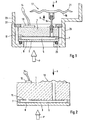
- FIG. 1 shows a section through a relative pressure sensor according to the invention.
- the heart of the relative pressure sensor is in the embodiment shown, a capacitive ceramic pressure measuring cell.
- This has a main body 1 and a measuring diaphragm 3.
- the main body 1 consists e.g. made of ceramic.
- the measuring diaphragm 3 may also be made of ceramic or e.g. made of sapphire.
- the measuring diaphragm 3 and the main body 1 are pressure-tight and gastight connected to each other at the edge thereof to form a measuring chamber 5 by means of a joint 7.
- the measuring diaphragm 3 is pressure-sensitive, i. a pressure acting on it causes a deflection of the measuring diaphragm 3 from its rest position.
- the measuring diaphragm 3 closes the measuring chamber 5.
- an electrode 9 On an inner side of the measuring diaphragm 3 is an electrode 9 and on an opposite inner side of the base body 1 at least one counter electrode 11 is arranged.
- the electrode 9 of the measuring diaphragm 3 is electrically contacted by the joint 7 and connected outside, for example, to ground.
- the counterelectrode 11 of the main body 1 is electrically contacted by the main body 1 to the outside thereof and leads to an arranged on the base body 1 electronic circuit 13.
- electrode 9 and counter electrode 11 form a capacitor and the electronic circuit 13 transforms the capacitance changes of the capacitor, for example, in a correspondingly changing electrical voltage.
- a pressure P to be measured acts on an outside of the measuring diaphragm 3. This is shown symbolically in FIG. 1 by an arrow.
- the pressure P causes a pressure-dependent deflection of the measuring diaphragm 3 which is converted by a converter into an electrical measured variable.
- the transducer comprises the electrode 9, the counter electrode 11 and the electronic circuit 13, and the electrical quantity is e.g. a tension.
- the measured variable is available via connecting lines 14 for further processing and / or evaluation.
- the transducer has strain gauges applied to the measuring diaphragm.
- the measuring chamber can also be formed in these measuring cells by a base body on which the measuring diaphragm is fixed with its outer edge, and the measuring diaphragm itself.
- the main body 1 has a through hole into which a tube 15 is inserted.
- a resilient bellows 17 is arranged, on the sides in operation a reference pressure R acts. This is indicated in Fig. 1 by arrows.
- the interior of the bellows 17 is connected via the tube 15 with the measuring chamber 5.
- the measuring chamber 5, the tube 15 and the bellows 17 are filled with a gas, for example with air.
- the gas-filled space is hermetically sealed and thus protected from moisture and / or contamination.
- the bellows 17 is compressible. Consequently, its internal volume is dependent on the reference pressure acting on the bellows 17 from the outside. If the reference pressure R rises, the bellows 17 is compressed and the pressure in the interior of the bellows 17 increases until a balance of forces is established on the bellows 17. Since the interior of the bellows 17 is connected to the measuring chamber 3 via the tube 15, an internal pressure prevailing in the measuring chamber 5 is equal to the pressure which sets in the interior of the bellows 17 as a function of the reference pressure R.
- the bellows 17 consists of two at the outer edge interconnected thin membranes 19, 21.
- the two membranes 19, 21 are preferably, as shown in Fig. 1 formed as a corrugated membranes.
- This has the advantage that the inner volume of the bellows 17 is relatively low at a mean reference pressure, the bellows 17 but by a deflection of both membranes away from each other can significantly increase its internal volume.
- the relative pressure sensor has a housing 23 in which the capacitive ceramic measuring cell is clamped.
- the housing 23 has an opening with a radially inwardly extending shoulder on which the measuring diaphragm 3 rests with an outer pressure insensitive edge with the interposition of a seal 25, for example an O-ring.
- a threaded ring 27 is screwed into the housing 23, through which the measuring cell against the seal 25th is pressed.
- an external thread 29 is provided on the housing 23. Other types of attachment are also applicable.
- a further pressure measuring cell with a gas-filled resilient bellows 18 is shown.
- the pressure measuring cell can be installed in the same manner in a housing as the pressure measuring cell shown in Fig. 1.
- the two pressure measuring cells differ only by the shape and the arrangement of the bellows 17 and 18.
- the base body 1 has a through hole.
- the bellows 18 consists of a thin, slightly curved corrugated membrane. An outer edge of the bellows 18 is connected to a side facing away from the measuring diaphragm 3 back of the base body 1.
- the corrugated membrane encloses with the base body 1 a small volume and covers the through hole.
- the interiors of the bellows 18, the bore and the measuring chamber 5 form a single gas-tight cavity which is filled with a gas, e.g. Air is filled.
- a gas e.g. Air is filled.
- the reference pressure acts on the bellows 18 from the outside. The operation corresponds to that of the embodiment described above.
- the bellows 17, 18 has a rigidity which is small in comparison to a rigidity of the measuring diaphragm 3.
- the rigidity of measuring diaphragm 3 and bellows 17, 18 is determined by the material properties of the materials used, their thickness and their Shaping determined. The sensitivity of the relative pressure sensor and thus the best achievable accuracy is limited by the rigidity of the measuring diaphragm 3.
- elastic materials esp. Metals such. a copper berrylium alloy. But it is also a stainless steel or a resilient plastic used. Such elastic materials also offer the advantage of a very low deformation hysteresis.
- the rigidity of bellows 17, 18 and measuring diaphragm 3 can be stated quantitatively in the form of a pressure / volume constant.
- an acting pressure is referred to a change in the inside of the bellows or of the interior of the measuring chamber caused by this pressure.
- the pressure / volume constant can be determined either experimentally or approximately mathematically. With suitable dimensioning, the pressure / volume constant can be smaller by a factor of 1000 to 10,000 than that of the measuring diaphragm 3.
- the bellows 17 at a diameter of 23 mm and a thickness of the membranes 19, 21 of 20 microns, a pressure / volume constant of about 5 Pa / mm 3 ( 0.05 mbar / mm 3 ), wherein the membranes 19, 21 are formed as corrugated membranes and consist of copper berrylium alloy.
Landscapes
- Physics & Mathematics (AREA)
- General Physics & Mathematics (AREA)
- Chemical & Material Sciences (AREA)
- Engineering & Computer Science (AREA)
- Ceramic Engineering (AREA)
- Measuring Fluid Pressure (AREA)
Description
Die Erfindung betrifft einen Relativdrucksensor.The invention relates to a relative pressure sensor.
In der Druckmeßtechnik wird zwischen Differenz-, Absolut- und Relativdrucksensoren unterschieden. Differenzdrucksensoren dienen der Messung der Differenz zwischen zwei verschiedenen Drücken. Bei Absolutdrucksensoren wird ein zu messender Druck absolut, d.h. als Druckunterschied gegenüber einem Vakuum erfaßt. Mit einem Relativdrucksensor wird ein zu messender Druck in Form eines Druckunterschiedes gegenüber einem Referenzdruck aufgenommen. Der Referenzdruck ist ein Umgebungsdruck der dort herrscht, wo sich der Sensor befindet. Bei den meisten Anwendungen ist dies der Atmosphärendruck am Einsatzort. Relativdrucksensoren weisen üblicherweise eine Meßkammer auf, die mit einer druckempfindlichen Meßmembran verschlossen ist. Auf eine Außenseite der Meßmembran wirkt im Betrieb der zu messende Druck ein. Auf einer meßmembran-abgewandten Seite weist die Kammern eine Öffnung auf, durch die der Referenzdruck im Inneren der Kammer an der Meßmembran anliegt. Es ist ein Wandler vorgesehen, der eine vom Referenzdruck und vom zu messenden Druck abhängige Auslenkung der Meßmembran in eine elektrische Meßgröße umwandelt.In pressure measurement, a distinction is made between differential, absolute and relative pressure sensors. Differential pressure sensors are used to measure the difference between two different pressures. In absolute pressure sensors, a pressure to be measured becomes absolute, i. detected as a pressure difference to a vacuum. With a relative pressure sensor, a pressure to be measured is recorded in the form of a pressure difference with respect to a reference pressure. The reference pressure is an ambient pressure prevailing where the sensor is located. For most applications, this is atmospheric pressure at the jobsite. Relative pressure sensors usually have a measuring chamber which is closed by a pressure-sensitive measuring diaphragm. In operation, the pressure to be measured acts on an outer side of the measuring diaphragm. On a meßmembran-side facing away from the chambers, an opening through which the reference pressure in the interior of the chamber rests against the measuring diaphragm. It is provided a converter which converts a dependent of the reference pressure and the pressure to be measured deflection of the measuring diaphragm into an electrical measured variable.
Ein Nachteil solcher Sensoren besteht darin, daß durch die der Zufuhr des Referenzdrucks dienende Öffnung Verunreinigungen und/oder Feuchtigkeit in die Meßkammer gelangen können, die die Meßgenauigkeit beeinträchtigen. Verunreinigungen können z.B. in der Luft enthaltene Staubpartikel sein oder aber auch am Einsatzort vorhandene aggressive oder ätzende Schwebstoffe, die sich in der Kammer ablagern können. Ist die Temperatur in der Umgebung höher als die Temperatur im Inneren der Kammer, so kann im Inneren der Kammer der Taupunkt unterschritten werden und es bildet sich Kondesat.A disadvantage of such sensors is that contaminants and / or moisture entering the measuring chamber through the opening serving to supply the reference pressure can affect the measuring accuracy. Contaminants may be, for example, dust particles contained in the air or else aggressive or caustic suspended solids present at the place of use which may be deposited in the chamber. If the temperature in the environment is higher than the temperature inside the chamber, it may be in the Inside the chamber below the dew point and it forms Kondesat.
Elektromechanische Wandler, wie sie zur Erfassung der Auslenkung der Meßmembran erforderlich sind, sind in der Regel sehr empfindlich gegenüber Verunreinigungen und/oder Feuchtigkeit.Electromechanical transducers, as required for detecting the deflection of the measuring diaphragm, are generally very sensitive to contamination and / or moisture.
In der EP-B 524 550 ist ein Relativdrucksensor beschrieben mit
- einer gasgefüllten Meßkammer,
- -- die mit einer druckempfindlichen Meßmembran verschlossen ist,
- -- auf deren Außenseite im Betrieb ein zu messender Druck einwirkt, und
- einem Wandler zur Umwandlung einer vom zu messenden Druck abhängigen Auslenkung der Membran in eine elektrische Meßgröße.
- a gas-filled measuring chamber,
- - which is closed with a pressure-sensitive measuring membrane,
- - On the outside of which in operation a pressure to be measured acts, and
- a transducer for converting a dependent of the pressure to be measured deflection of the membrane into an electrical measurement.
Neben der Meßkammer ist eine weitere gasgefüllte Kammer vorgesehen, die mit einer weiteren druckempfindlichen Membran verschlossen ist, auf deren Außenseite im Betrieb der Referenzdruck einwirkt. Zur Umwandlung einer druckabhängigen Auslenkung dieser weiteren Membran in eine elektrische Größe ist ein zweiter Wandler vorgesehen. Die Meßkammer und die weitere Kammer sind über eine Leitung miteinander verbunden. Das Volumen der beiden Kammern ist jedoch ausreichend groß, so daß die Auslenkungen der Meßmembran und der weiteren Membran weitgehend unabhängig voneinander sind. Der Relativdrucksensor besteht also effektiv aus zwei getrennten Sensoren, von denen einer den zu messenden Druck und einer den Referenzdruck aufnimmt. Die unabhängig voneinander bestimmten Meßgrößen werden nachfolgend zur Ermittlung des Relativdrucks miteinander verknüpft.In addition to the measuring chamber, a further gas-filled chamber is provided, which is closed by a further pressure-sensitive membrane, acting on the outside of the reference pressure during operation. For converting a pressure-dependent deflection of this further membrane into an electrical variable, a second converter is provided. The measuring chamber and the further chamber are connected to one another via a line. However, the volume of the two chambers is sufficiently large, so that the deflections of the measuring membrane and the other membrane are largely independent of each other. The relative pressure sensor thus effectively consists of two separate sensors, one of which receives the pressure to be measured and the reference pressure. The independently determined measured variables are subsequently linked together to determine the relative pressure.
Ein Nachteil eines solchen Relativdrucksensors besteht darin, daß zwei Wandler erforderlich sind, um den Referenzdruck und den zu messenden Druck unabhängig voneinander zu erfassen. Dies bedeutet einen höheren Aufwand und höhere Kosten bei der Herstellung.A disadvantage of such a relative pressure sensor is that two transducers are required to independently detect the reference pressure and the pressure to be measured. This means a higher cost and higher costs in the production.
Ein weiterer Nachteil besteht darin, daß beide Kammern zur Entkopplung der beiden Sensoren ein großes Innenvolumen aufweisen. Entsprechend groß ist die darin enthaltene Gasmenge. Der Druck im Inneren der Kammern erhöht bzw. erniedrigt sich mit der Temperatur. Ein höherer bzw. niedrigerer Druck im Inneren führt zu einer Auslenkung der beiden Membranen und zu Meßfehlern. Je kleiner zumindest einer der zu bestimmenden Drücke ist, desto stärker wirkt sich diese Fehlerquelle aus. Es gehen bei dieser Form der Relativdruckbestimmung die Meßfehler beider Druckmessungen kumulativ ein.Another disadvantage is that both chambers for decoupling the two sensors have a large internal volume. The amount of gas contained in it is correspondingly large. The pressure inside the chambers increases or decreases with the temperature. A higher or lower pressure inside leads to a deflection of the two membranes and to measurement errors. The smaller at least one of the pressures to be determined, the stronger this source of error affects. In this form of relative pressure determination, the measurement errors of both pressure measurements are cumulative.
In der US-A 4,425,799 ist ein Differenzdrucksensor mit zwei ölgefüllten über eine Leitung mit einander verbundenen Kammern beschrieben. Jede Kammer ist mit einer druckempfindlichen Membran verschlossen. An jeder Membran liegt im Betrieb einer der Drücke an, deren Differenz gemessen werden soll. Das Öl dient als Druckübertrager und weist einen deutlich geringeren thermischen Ausdehnungskoeffizienten auf als Luft. Es ist somit nur ein Wandler erforderlich, der die vom Differenzdruck abhängige Auslenkung einer der beiden Membranen erfaßt und in eine elektrische Größe umwandelt.In US-A 4,425,799 a differential pressure sensor is described with two oil-filled via a line with interconnected chambers. Each chamber is closed with a pressure-sensitive membrane. During operation, each of the diaphragms has one of the pressures whose difference is to be measured. The oil serves as a pressure transmitter and has a significantly lower coefficient of thermal expansion than air. Thus, only one transducer is required, which detects the differential pressure dependent deflection of one of the two membranes and converts it into an electrical variable.
Es gibt jedoch eine Vielzahl von Anwendungen, bei denen aus Sicherheitsgründen keine ölgefüllten Sensoren eingesetzt werden dürfen, da die Gefahr besteht, daß eine Membran beschädigt wird und Öl ausläuft. Beispiele für solche Anwendungen finden sich insb. in der Lebensmittelindustrie und bei der Herstellung und Lagerung von Lacken.However, there are a variety of applications where for safety reasons, oil-filled sensors may not be used, since there is a risk that a membrane is damaged and oil leaks. Examples of such applications are esp. In the food industry and in the manufacture and storage of paints.
Es ist eine Aufgabe der Erfindung, einen Relativdrucksensor anzugeben, der gegenüber Verunreinigungen und/oder Feuchtigkeit geschützt ist und ohne Ölfüllung auskommt.It is an object of the invention to provide a relative pressure sensor which is protected against contamination and / or moisture and manages without oil filling.
Hierzu besteht die Erfindung in einem Relativdrucksensor mit
- einer gasgefüllten Meßkammer,
- -- die mit einer druckempfindlichen Meßmembran verschlossen ist,
- -- auf deren Außenseite im Betrieb ein zu messender Druck einwirkt,
- einem gasgefüllten kompressiblen federelastischen Balg,
- -- auf den im Betrieb von außen ein Referenzdruck einwirkt,
- -- dessen Innenvolumen vom Referenzdruck abhängt und
- -- der zur Anpassung eines in der Meßkammer herrschenden Innendrucks an den Referenzdruck mit der Meßkammer verbunden ist, und
- einem Wandler zur Umwandlung einer druckabhängigen Auslenkung der Meßmembran in eine elektrische Meßgröße.
- a gas-filled measuring chamber,
- - which is closed with a pressure-sensitive measuring membrane,
- on the outside of which, during operation, a pressure to be measured acts,
- a gas-filled compressible spring-loaded bellows,
- - acts on the outside during operation from a reference pressure,
- - whose internal volume depends on the reference pressure and
- - Is connected to adapt a prevailing in the measuring chamber internal pressure to the reference pressure to the measuring chamber, and
- a converter for converting a pressure-dependent deflection of the measuring diaphragm into an electrical measured quantity.
Gemäß einer Weiterbildung der Erfindung besteht der Balg aus zwei an deren äußeren Rand miteinander verbundenen Membranen, vorzugsweise aus Wellmembranen.According to one embodiment of the invention, the bellows consists of two at the outer edge interconnected membranes, preferably of corrugated membranes.
Gemäß einer anderen Weiterbildung ist die Meßmembran auf einem Grundkörper angeordnet, der Grundkörper weist eine durchgehende Bohrung auf und der Balg ist eine Wellmembran, die mit einem äußeren Rand mit einer von der Meßmembran abgewandten Rückseite des Grundkörpers verbunden ist und die die Bohrung überdeckt.According to another embodiment, the measuring diaphragm is arranged on a base body, the base body has a through bore and the bellows is a corrugated membrane, which is connected to an outer edge facing away from the measuring membrane back of the body and which covers the bore.
Gemäß einer weiteren Weiterbildung weist der Balg eine Steifigkeit auf, die klein ist im Vergleich zu einer Steifigkeit der Meßmembran.According to a further development, the bellows has a rigidity which is small in comparison to a rigidity of the measuring diaphragm.
Gemäß einer Ausgestaltung besteht der Balg aus einem Edelstahl oder aus einer Kupfer-Berrylium-Legierung.According to one embodiment, the bellows consists of a stainless steel or a copper berrylium alloy.
Die Erfindung und weitere Vorteile werden nun anhand der Figuren der Zeichnung, in denen zwei Ausführungsbeispiele dargestelltsind, näher erläutert. Gleiche Elemente sind in den Figuren mit den gleichen Bezugszeichen versehen.
- Fig. 1
- zeigt einen Schnitt durch einen Relativdrucksensor mit einem aus zwei Membranen bestehenden Balg ; und
- Fig. 2
- zeigt eine Druckmeßzelle mit einem eine Membran aufweisenden Balg.
- Fig. 1
- shows a section through a relative pressure sensor with a two-diaphragm bellows; and
- Fig. 2
- shows a pressure measuring cell with a diaphragm having a bellows.
In Fig. 1 ist ein Schnitt durch einen erfindungsgemäßen Relativdrucksensor dargestellt. Das Herzstück des Relativdrucksensors ist in dem gezeigten Ausführungsbeispiel eine kapazitive keramische Druckmeßzelle. Diese weist einen Grundkörper 1 und eine Meßmembran 3 auf. Der Grundkörper 1 besteht z.B. aus Keramik. Die Meßmembran 3 kann ebenfalls aus Keramik bestehen oder z.B. aus Saphir. Die Meßmembran 3 und der Grundkörper 1 sind an deren Rand unter Bildung einer Meßkammer 5 mittels einer Fügestelle 7 druckdicht und gasdicht miteinander verbunden. Die Meßmembran 3 ist druckempfindlich, d.h. ein auf sie einwirkender Druck bewirkt eine Auslenkung der Meßmembran 3 aus deren Ruhelage.. Die Meßmembran 3 verschließt die Meßkammer 5.FIG. 1 shows a section through a relative pressure sensor according to the invention. The heart of the relative pressure sensor is in the embodiment shown, a capacitive ceramic pressure measuring cell. This has a main body 1 and a measuring
Auf einer Innenseite der Meßmembran 3 ist eine Elektrode 9 und auf einer gegenüberliegenden Innenseite des Grundkörpers 1 ist mindestens eine Gegenelektrode 11 angeordnet. Die Elektrode 9 der Meßmembran 3 ist durch die Fügestelle 7 hindurch elektrisch kontaktiert und außerhalb z.B. mit Masse verbunden. Die Gegenelektrode 11 des Grundkörpers 1 ist durch den Grundkörper 1 hindurch zu dessen Außenseite hin elektrisch kontaktiert und führt zu einer auf dem Grundkörper 1 angeordneten elektronischen Schaltung 13. Elektrode 9 und Gegenelektrode 11 bilden einen Kondensator und die elektronische Schaltung 13 formt die Kapazitätsänderungen des Kondensators z.B. in eine sich entsprechend ändernde elektrische Spannung um.On an inner side of the measuring
Im Betrieb wirkt auf eine Außenseite der Meßmembran 3 ein zu messender Druck P ein. Dies ist in Fig. 1 durch einen Pfeil symbolisch dargestellt. Der Druck P bewirkt eine druckabhängige Auslenkung der Meßmembran 3 die von einem Wandler in eine elektrische Meßgröße umgewandelt wird. Bei dem beschriebenen Ausführungsbeispiel umfaßt der Wandler die Elektrode 9, die Gegenelektrode 11 und die elektronische Schaltung 13 und die elektrische Meßgröße ist z.B. eine Spannung. De Meßgröße steht über Anschlußleitungen 14 einer weiteren Verarbeitung und/oder Auswertung zur Verfügung.In operation, a pressure P to be measured acts on an outside of the measuring
Anstatt der beschriebenen kapazitiven keramischen Meßzelle kann z.B. auch eine piezoresistive Meßzelle verwendet werden. Bei diesen Arten von Meßzellen weist der Wandler auf der Meßmembran aufgebrachte Dehnmeßstreifen auf. Die Meßkammer kann auch bei diesen Meßzellen durch einen Grundkörper, auf dem die Meßmembran mit deren äußerem Rand befestigt wird, und die Meßmembran selber gebildet sein.Instead of the described capacitive ceramic measuring cell, e.g. also a piezoresistive measuring cell can be used. In these types of measuring cells, the transducer has strain gauges applied to the measuring diaphragm. The measuring chamber can also be formed in these measuring cells by a base body on which the measuring diaphragm is fixed with its outer edge, and the measuring diaphragm itself.
Der Grundkörper 1 weist eine durchgehende Bohrung auf, in die ein Röhrchen 15 eingeführt ist. An einem grundkörperabgewandten Ende des Röhrchens 15 ist ein federelastischer Balg 17 angeordnet, auf den im Betrieb von außen allseitig ein Referenzdruck R einwirkt. Dies ist in Fig. 1 durch Pfeile gekennzeichnet. Der Innenraum des Balgs 17 ist über das Röhrchen 15 mit der Meßkammer 5 verbunden. Die Meßkammer 5, das Röhrchen 15 und der Balg 17 sind mit einem Gas, z.B. mit Luft, gefüllt. Der gasgefüllte Raum ist hermetisch dicht verschlossen und somit sicher vor Feuchtigkeit und/oder Verunreinigungen geschützt.The main body 1 has a through hole into which a
Der Balg 17 ist kompressibel. Folglich ist dessen Innenvolumen abhängig von dem von außen auf den Balg 17 einwirkenden Referenzdruck R. Steigt der Referenzdruck R wird der Balg 17 komprimiert und der Druck im Inneren des Balgs 17 steigt an bis sich am Balg 17 ein Kräftegleichgewicht einstellt. Da der Innenraum des Balgs 17 mit der Meßkammer 3 über das Röhrchen 15 verbunden ist, ist ein in der Meßkammer 5 herrschender Innendruck gleich dem Druck, der sich im Inneren des Balgs 17 in Abhängigkeit vom Referenzdruck R einstellt.The bellows 17 is compressible. Consequently, its internal volume is dependent on the reference pressure acting on the
In dem in Fig. 1 dargestellten Ausführungsbeispiel besteht der Balg 17 aus zwei an deren äußeren Rand miteinander verbundenen dünnen Membranen 19, 21. Die beiden Membranen 19, 21 sind vorzugsweise, wie in Fig. 1 dargestellt als Wellmembranen ausgebildet. Dies bietet den Vorteil, daß das Innenvolumen des Balgs 17 bei einem mittleren Referenzdruck verhältnismäßig gering ist, der Balg 17 aber durch eine Auslenkung beider Membranen voneinander weg sein Innenvolumen deutlich vergrößern kann. Das bedeutet zum einen, daß nur eine geringe Gasmenge vorhanden ist, die sich mit der Temperatur ausdehnt, und zum anderen, daß eine temperaturbedingte Gasausdehnung von dem Balg 17 aufgenommen wird, ohne daß sich der Druck der sich im Inneren des Balgs 17 und damit in der Meßkammer 5 bei einem bestimmten Referenzdruck R einstellt wesentlich ändert.In the embodiment shown in Fig. 1, the
Der Relativdrucksensor weist ein Gehäuse 23 auf in das die kapazitive keramische Meßzelle eingespannt ist. Hierzu weist das Gehäuse 23 eine Öffnung mit einer sich radial nach innen erstreckenden Schulter auf, auf der die Meßmembran 3 mit einem äußeren druckunempfindlichen Rand unter Zwischenfügung einer Dichtung 25, z.B. eines O-Rings, aufliegt. Auf einer meßmembran-abgewandten Seite der Meßzelle ist ein Gewindering 27 in das Gehäuse 23 eingeschraubt, durch den die Meßzelle gegen die Dichtung 25 gepreßt wird. Zur Befestigung des Sensors an einem Meßort ist an dem Gehäuse 23 ein Außengewinde 29 vorgesehen. Andere Arten der Befestigung sind ebenfalls einsetzbar.The relative pressure sensor has a
In Fig. 2 ist eine weitere Druckmeßzelle mit einem gasgefüllten federelastischen Balg 18 dargestellt. Die Druckmeßzelle kann auf die gleiche Weise in ein Gehäuse eingebaut sein, wie die in Fig. 1 dargestellte Druckmeßzelle. Die beiden Druckmeßzellen unterscheiden sich lediglich durch die Form und die Anordnung des Balgs 17 bzw. 18. Auch bei dem Ausführungsbeispiel von Fig. 2 weist der Grundkörper 1 eine durchgehende Bohrung auf. Der Balg 18 besteht in einer dünnen leicht gewölbten Wellmembran. Ein äußerer Rand des Balgs 18 ist mit einer von der Meßmembran 3 abgewandten Rückseite des Grundkörpers 1 verbunden. Die Wellmembran schließt mit dem Grundkörper 1 ein geringes Volumen ein und überdeckt die durchgehende Bohrung. Die Innenräume des Balgs 18, der Bohrung und der Meßkammer 5 bilden einen einzigen gasdicht verschlossenes Hohlraum, der mit einem Gas, z.B. Luft gefüllt ist. Der Referenzdruck wirkt von außen auf den Balg 18 ein. Die Funktionsweise entspricht der des zuvor beschriebenen Ausführungsbeispiels.2, a further pressure measuring cell with a gas-filled
Es ist jeweils von Vorteil, wenn der Balg 17, 18 eine Steifigkeit aufweist, die klein ist im Vergleich zu einer Steifigkeit der Meßmembran 3. Die Steifigkeit von Meßmembran 3 und Balg 17, 18 wird durch die Materialeigenschaften der verwendeten Werkstoffe, deren Dicke und deren Formgebung bestimmt. Die Empfindlichkeit des Relativdrucksensors und damit die bestenfalls erzielbare Meßgenauigkeit ist durch die Steifigkeit der Meßmembran 3 begrenzt. Je geringer die Steifigkeit des Balgs 17, 18 ist, um so weicher ist er, um so genauer folgt der Innendruck dem Referenzdruck R und um so geringer sind die Auswirkungen des Membranbalgs 17 bzw. 18 auf ein Meßsignal. Ist die Steifigkeit des Balgs 17,18 gering im Vergleich zu der der Meßmembran 3, so folgt der Innendruck dem Referenzdruck R mit einer Genauigkeit, die innerhalb der durch die Meßmembran 3 vorgegebenen Meßgenauigkeit liegt.It is in each case advantageous if the bellows 17, 18 has a rigidity which is small in comparison to a rigidity of the measuring
Besonders geeignet sind federelastische Materialien, insb. Metalle wie z.B. eine Kupfer-Berrylium-Legierung. Es ist aber auch ein Edelstahl oder ein federelastischer Kunstoff einsetzbar. Solche federelastischen Materialien bieten weiter den Vorteil einer sehr geringen Hysterese bei Verformungen.Particularly suitable are elastic materials, esp. Metals such. a copper berrylium alloy. But it is also a stainless steel or a resilient plastic used. Such elastic materials also offer the advantage of a very low deformation hysteresis.
Die Steifigkeit von Balg 17, 18 und Meßmembran 3 kann in Form einer Druck/Volumen-Konstante quantitativ angegeben werden. Es wird dabei ein einwirkender Druck auf eine durch diesen Druck bedingte Änderung des Balginnenvolumens bzw. des Meßkammerinnenvolumens bezogen. Die Druck/Volumen-Konstante kann entweder experimentel oder näherungsweise rechnerisch bestimmt werden. Bei geeigneter Dimensionierung kann die Druck/Volumen-Konstante um einen Faktor 1000 bis 10000 geringer sein als die der Meßmembran 3.The rigidity of
Ein Relativdrucksensor gemäß dem Ausführungsbeispiel von Fig. 1, der z.B. für einen Meßbereich von 40 kPa (= 400 mbar) ausgelegt ist, weist bei Verwendung einer kreisscheibenförmige Meßmembran 3 aus einer Aluminuimoxid-Keramik mit einer Dicke von 0,25 mm und einem Durchmesser von 25 mm eine Druck/Volumen-Konstante von ungefähr 30 kPa/mm3 (= 300 mbar/mm3) auf. Demgegenüber weist der Balg 17 bei einem Durchmesser von 23 mm und einer Dicke der Membranen 19, 21 von 20 µm eine Druck/Volumen-Kontante von ungefähr 5 Pa/mm3 (= 0,05 mbar/mm3) auf, wobei die Membranen 19, 21 als Wellmembranen ausgebildet sind und aus Kupfer-Berrylium-Legierung bestehen.A relative pressure sensor according to the embodiment of FIG. 1, which is designed for example for a measuring range of 40 kPa (= 400 mbar), comprises, when using a circular disk-shaped
Wie bei Relativdrucksensoren generell üblich, wird auch bei den erfindungsgemäßen Relativdrucksensoren eine Kalibration über Druck und Temperatur vorgenommen werden. Dabei wird werkseitig von einem vorgegebenen mittleren Referenzdruck, z.B. 1,013 105 Pa (= 1013 mbar), ausgegangen. Aufgrund der Federelastizität und der geringen Steifigkeit der Bälge 17, 18 können diese Relativdrucksensoren relativ große Abweichungen eines mittleren Referenzdrucks von dem vorgegebenen mittleren Referenzdruck aufnehmen, ohne daß ein linearer Bereich der Sensorkennlinie verlassen wird. Innerhalb dieses linearen Bereichs genügt eine Einstellung des Nullpunkts des Relativdrucksensors Vorort, um die gleiche Meßgenauigkeit zu erhalten wie sie bei dem vorgegebenen mittleren Referenzdruck erzielt wird. Ein auf Meereshöhe kalibrierter Relativdrucksensor kann somit ohne Genauigkeitseinbußen auch in den Bergen, z.B. in einer Höhe von 2000 m eingesetzt werden.As is generally customary with relative pressure sensors, calibration is also effected in the case of the relative pressure sensors according to the invention be made via pressure and temperature. The factory presupposes a given average reference pressure, eg 1.013 10 5 Pa (= 1013 mbar). Due to the spring elasticity and the low rigidity of the
Claims (6)
- Relative-pressure sensor having- a gas-filled measuring chamber (5), which is sealed with a pressure-sensitive measuring diaphragm (3),-- on the outer side of which a pressure (P) to be measured acts during operation,- a gas-filled compressible resilient bellows (17, 18),-- on which a reference pressure (R) acts from outside during operation,-- whose internal volume depends on the reference pressure (R), and-- which is connected to the measuring chamber (5) in order to adapt an internal pressure prevailing in the measuring chamber (5) to the reference pressure (R), and- a transducer for converting a pressure-dependent deflection of the measuring diaphragm (3) into an electric measured variable.
- Relative-pressure sensor according to Claim 1, in which the bellows (17) comprises two diaphragms (19, 21) interconnected at their outer edge.
- Relative-pressure sensor according to Claim 2, in which the diaphragms (19, 21) are corrugated diaphragms.
- Relative-pressure sensor according to Claim 1, in which- the measuring diaphragm (3) is arranged on a basic body (1),- the basic body (1) has a continuous bore, and- the bellows (18) is a corrugated diaphragm-- which is connected with an outer edge to a rear side of the basic body (1) averted from the measuring diaphragm (3) and-- covers the bore.
- Relative-pressure sensor according to one of the preceding claims, in which the bellows (17, 18) has a stiffness which is small in comparison with a stiffness of the measuring diaphragm (3).
- Relative-pressure sensor according to one of the preceding claims, in which the bellows (17, 18) is made of a high-grade steel or a copper-beryllium alloy.
Priority Applications (6)
| Application Number | Priority Date | Filing Date | Title |
|---|---|---|---|
| DE59914223T DE59914223D1 (en) | 1999-07-01 | 1999-07-01 | Relative pressure sensor |
| EP19990112538 EP1065488B1 (en) | 1999-07-01 | 1999-07-01 | Relative pressure sensor |
| US09/604,359 US6425291B1 (en) | 1999-07-01 | 2000-06-27 | Relative-pressure sensor having a gas-filled bellows |
| JP2000196988A JP3325879B2 (en) | 1999-07-01 | 2000-06-29 | Relative pressure sensor |
| CNB001199048A CN1135376C (en) | 1999-07-01 | 2000-06-30 | Relative pressure sensor |
| CA 2313313 CA2313313C (en) | 1999-07-01 | 2000-06-30 | Relative pressure sensor |
Applications Claiming Priority (1)
| Application Number | Priority Date | Filing Date | Title |
|---|---|---|---|
| EP19990112538 EP1065488B1 (en) | 1999-07-01 | 1999-07-01 | Relative pressure sensor |
Publications (2)
| Publication Number | Publication Date |
|---|---|
| EP1065488A1 EP1065488A1 (en) | 2001-01-03 |
| EP1065488B1 true EP1065488B1 (en) | 2007-02-28 |
Family
ID=8238469
Family Applications (1)
| Application Number | Title | Priority Date | Filing Date |
|---|---|---|---|
| EP19990112538 Expired - Lifetime EP1065488B1 (en) | 1999-07-01 | 1999-07-01 | Relative pressure sensor |
Country Status (5)
| Country | Link |
|---|---|
| EP (1) | EP1065488B1 (en) |
| JP (1) | JP3325879B2 (en) |
| CN (1) | CN1135376C (en) |
| CA (1) | CA2313313C (en) |
| DE (1) | DE59914223D1 (en) |
Cited By (2)
| Publication number | Priority date | Publication date | Assignee | Title |
|---|---|---|---|---|
| DE102009028488A1 (en) * | 2009-08-12 | 2011-02-17 | Endress + Hauser Gmbh + Co. Kg | Relative pressure sensor |
| DE102011017265A1 (en) * | 2011-04-15 | 2012-10-18 | Armaturenbau Gmbh | Reference pressure gauge for measuring pressure of container, has sensor element that is located within pressure chamber at backside of diaphragm, for sensing atmospheric pressure which is acted on outer side portion of diaphragm |
Families Citing this family (14)
| Publication number | Priority date | Publication date | Assignee | Title |
|---|---|---|---|---|
| JP4828030B2 (en) * | 2001-02-27 | 2011-11-30 | ミネベア株式会社 | Semiconductor pressure sensor for high temperature measurement |
| JP4925522B2 (en) * | 2001-04-27 | 2012-04-25 | 京セラ株式会社 | Package for pressure detection device |
| DE10234754A1 (en) * | 2002-07-30 | 2004-02-19 | Endress + Hauser Gmbh + Co. Kg | Differential pressure sensor with symmetrical separator error |
| DE102004051219B4 (en) * | 2004-10-20 | 2013-03-14 | Endress + Hauser Gmbh + Co. Kg | pressure transducers |
| DE102007040080A1 (en) * | 2007-08-24 | 2009-02-26 | BSH Bosch und Siemens Hausgeräte GmbH | Apparatus and method for determining a level within a tub of a washing machine |
| DE112008003344A5 (en) * | 2007-12-20 | 2010-12-09 | Inficon Gmbh | Arrangement for a diaphragm pressure measuring cell |
| KR100981928B1 (en) * | 2008-03-17 | 2010-09-13 | (주)와이즈산전 | Capacitive-hybrid pressure transmitter |
| ES2414230T5 (en) * | 2010-12-07 | 2016-03-08 | Vega Grieshaber Kg | Pressure measuring cell |
| DE102011102837A1 (en) * | 2011-05-30 | 2012-12-06 | Epcos Ag | Pressure sensor and method for producing a pressure sensor |
| JP5970485B2 (en) * | 2012-02-16 | 2016-08-17 | 北陸電気工業株式会社 | Pressure sensor module |
| DE102013114608A1 (en) * | 2013-12-20 | 2015-07-09 | Endress + Hauser Gmbh + Co. Kg | Relative pressure sensor |
| CN104236787B (en) * | 2014-09-05 | 2017-03-15 | 龙微科技无锡有限公司 | MEMS differential pressure pick-ups chip and preparation method |
| CN108529030B (en) * | 2018-06-15 | 2024-03-01 | 江苏龙禾轻型材料有限公司 | Full liquid-receiving welding type inner floating disc |
| JP7105492B2 (en) * | 2019-02-25 | 2022-07-25 | ヤマシンフィルタ株式会社 | Differential pressure detector |
Family Cites Families (3)
| Publication number | Priority date | Publication date | Assignee | Title |
|---|---|---|---|---|
| US4212209A (en) * | 1978-09-07 | 1980-07-15 | Honeywell Inc. | Differential pressure to electric current transducer employing a strain sensitive resistive pattern on a substrate having a high modulus of elasticity |
| US4425799A (en) * | 1982-06-03 | 1984-01-17 | Kavlico Corporation | Liquid capacitance pressure transducer technique |
| DE4124662A1 (en) * | 1991-07-25 | 1993-01-28 | Fibronix Sensoren Gmbh | RELATIVE PRESSURE SENSOR |
-
1999
- 1999-07-01 EP EP19990112538 patent/EP1065488B1/en not_active Expired - Lifetime
- 1999-07-01 DE DE59914223T patent/DE59914223D1/en not_active Expired - Fee Related
-
2000
- 2000-06-29 JP JP2000196988A patent/JP3325879B2/en not_active Expired - Fee Related
- 2000-06-30 CN CNB001199048A patent/CN1135376C/en not_active Expired - Fee Related
- 2000-06-30 CA CA 2313313 patent/CA2313313C/en not_active Expired - Fee Related
Cited By (2)
| Publication number | Priority date | Publication date | Assignee | Title |
|---|---|---|---|---|
| DE102009028488A1 (en) * | 2009-08-12 | 2011-02-17 | Endress + Hauser Gmbh + Co. Kg | Relative pressure sensor |
| DE102011017265A1 (en) * | 2011-04-15 | 2012-10-18 | Armaturenbau Gmbh | Reference pressure gauge for measuring pressure of container, has sensor element that is located within pressure chamber at backside of diaphragm, for sensing atmospheric pressure which is acted on outer side portion of diaphragm |
Also Published As
| Publication number | Publication date |
|---|---|
| CN1290857A (en) | 2001-04-11 |
| JP2001033332A (en) | 2001-02-09 |
| JP3325879B2 (en) | 2002-09-17 |
| EP1065488A1 (en) | 2001-01-03 |
| CA2313313C (en) | 2005-04-12 |
| CN1135376C (en) | 2004-01-21 |
| DE59914223D1 (en) | 2007-04-12 |
| CA2313313A1 (en) | 2001-01-01 |
Similar Documents
| Publication | Publication Date | Title |
|---|---|---|
| EP1065488B1 (en) | Relative pressure sensor | |
| EP1128172B1 (en) | Pressure sensor | |
| US5712428A (en) | Pressure sensor with a solid to minimize temperature-related measurement error | |
| EP1883798B1 (en) | Pressure sensor using compressible sensor body | |
| EP0524550B1 (en) | Gas filled relative pressure sensor | |
| EP0759547A1 (en) | Pressure sensor | |
| DE10392622T5 (en) | Barometric pressure sensor | |
| EP1409979A1 (en) | Pressure sensor | |
| DE10227479A1 (en) | pressure gauge | |
| DE102009046692A1 (en) | Pressure e.g. absolute pressure, measuring device for industrial measurement engineering, has disks covering recess, and semiconductor pressure sensor attached on disks and comprising membrane carrier and measuring membrane | |
| EP1946060A1 (en) | Pressure sensor for hydraulic media in motor vehicle braking systems and use thereof | |
| US4499773A (en) | Variable capacitance pressure transducer | |
| EP0421394A2 (en) | Differential pressure measuring device | |
| US8739632B2 (en) | Pressure sensor structure and associated method of making a pressure sensor | |
| WO2004111594A1 (en) | Moisture-protected pressure sensor | |
| EP1325294B1 (en) | Membrane pressure sensor comprising a seal with a counter-deformation spring washer | |
| DE10223588B4 (en) | Pressure gauge and method for its manufacture | |
| WO2002018896A1 (en) | Pressure measuring cell | |
| DE102009045158A1 (en) | Sensor arrangement and method for producing a sensor arrangement | |
| EP2098845B1 (en) | Ceramic pressure sensor | |
| US6425291B1 (en) | Relative-pressure sensor having a gas-filled bellows | |
| US20020040605A1 (en) | Pressure measuring cell | |
| DE4315041C1 (en) | Sensor cell, e.g. for force and press. measurement - contains press. sensor with air=tight membrane and reference cap with further membrane on carrier with conducting tracks | |
| DE102020132687A1 (en) | pressure transducer | |
| DE102017214664A1 (en) | Pressure measuring cell and pressure gauge with such a pressure measuring cell |
Legal Events
| Date | Code | Title | Description |
|---|---|---|---|
| PUAI | Public reference made under article 153(3) epc to a published international application that has entered the european phase |
Free format text: ORIGINAL CODE: 0009012 |
|
| AK | Designated contracting states |
Kind code of ref document: A1 Designated state(s): DE FR GB IT |
|
| AX | Request for extension of the european patent |
Free format text: AL;LT;LV;MK;RO;SI |
|
| 17P | Request for examination filed |
Effective date: 20010118 |
|
| AKX | Designation fees paid |
Free format text: DE FR GB IT |
|
| RAP1 | Party data changed (applicant data changed or rights of an application transferred) |
Owner name: ENDRESS + HAUSER GMBH + CO.KG. |
|
| 17Q | First examination report despatched |
Effective date: 20050622 |
|
| GRAP | Despatch of communication of intention to grant a patent |
Free format text: ORIGINAL CODE: EPIDOSNIGR1 |
|
| GRAS | Grant fee paid |
Free format text: ORIGINAL CODE: EPIDOSNIGR3 |
|
| GRAA | (expected) grant |
Free format text: ORIGINAL CODE: 0009210 |
|
| AK | Designated contracting states |
Kind code of ref document: B1 Designated state(s): DE FR GB IT |
|
| REG | Reference to a national code |
Ref country code: GB Ref legal event code: FG4D Free format text: NOT ENGLISH |
|
| REF | Corresponds to: |
Ref document number: 59914223 Country of ref document: DE Date of ref document: 20070412 Kind code of ref document: P |
|
| GBT | Gb: translation of ep patent filed (gb section 77(6)(a)/1977) |
Effective date: 20070517 |
|
| ET | Fr: translation filed | ||
| PLBE | No opposition filed within time limit |
Free format text: ORIGINAL CODE: 0009261 |
|
| STAA | Information on the status of an ep patent application or granted ep patent |
Free format text: STATUS: NO OPPOSITION FILED WITHIN TIME LIMIT |
|
| 26N | No opposition filed |
Effective date: 20071129 |
|
| PGFP | Annual fee paid to national office [announced via postgrant information from national office to epo] |
Ref country code: DE Payment date: 20080722 Year of fee payment: 10 |
|
| PGFP | Annual fee paid to national office [announced via postgrant information from national office to epo] |
Ref country code: IT Payment date: 20080724 Year of fee payment: 10 Ref country code: FR Payment date: 20080715 Year of fee payment: 10 |
|
| PGFP | Annual fee paid to national office [announced via postgrant information from national office to epo] |
Ref country code: GB Payment date: 20080722 Year of fee payment: 10 |
|
| GBPC | Gb: european patent ceased through non-payment of renewal fee |
Effective date: 20090701 |
|
| REG | Reference to a national code |
Ref country code: FR Ref legal event code: ST Effective date: 20100331 |
|
| PG25 | Lapsed in a contracting state [announced via postgrant information from national office to epo] |
Ref country code: FR Free format text: LAPSE BECAUSE OF NON-PAYMENT OF DUE FEES Effective date: 20090731 |
|
| PG25 | Lapsed in a contracting state [announced via postgrant information from national office to epo] |
Ref country code: GB Free format text: LAPSE BECAUSE OF NON-PAYMENT OF DUE FEES Effective date: 20090701 |
|
| PG25 | Lapsed in a contracting state [announced via postgrant information from national office to epo] |
Ref country code: DE Free format text: LAPSE BECAUSE OF NON-PAYMENT OF DUE FEES Effective date: 20100202 |
|
| PG25 | Lapsed in a contracting state [announced via postgrant information from national office to epo] |
Ref country code: IT Free format text: LAPSE BECAUSE OF NON-PAYMENT OF DUE FEES Effective date: 20090701 |