EP1116086B1 - Systeme et procede permettant l'acces et l'exploitation a distance sur ordinateur personnel - Google Patents
Systeme et procede permettant l'acces et l'exploitation a distance sur ordinateur personnel Download PDFInfo
- Publication number
- EP1116086B1 EP1116086B1 EP99969512A EP99969512A EP1116086B1 EP 1116086 B1 EP1116086 B1 EP 1116086B1 EP 99969512 A EP99969512 A EP 99969512A EP 99969512 A EP99969512 A EP 99969512A EP 1116086 B1 EP1116086 B1 EP 1116086B1
- Authority
- EP
- European Patent Office
- Prior art keywords
- key
- view
- video
- mouse
- host
- Prior art date
- Legal status (The legal status is an assumption and is not a legal conclusion. Google has not performed a legal analysis and makes no representation as to the accuracy of the status listed.)
- Expired - Lifetime
Links
- 238000000034 method Methods 0.000 claims description 82
- 238000012545 processing Methods 0.000 claims description 64
- 230000008569 process Effects 0.000 claims description 56
- 239000003086 colorant Substances 0.000 claims description 43
- 230000006870 function Effects 0.000 claims description 40
- 238000004891 communication Methods 0.000 claims description 24
- 230000001360 synchronised effect Effects 0.000 claims description 6
- 238000012384 transportation and delivery Methods 0.000 claims description 5
- 241000699666 Mus <mouse, genus> Species 0.000 description 419
- 238000013459 approach Methods 0.000 description 69
- 238000012546 transfer Methods 0.000 description 69
- 230000008859 change Effects 0.000 description 46
- 230000009471 action Effects 0.000 description 32
- 238000012549 training Methods 0.000 description 30
- 230000000694 effects Effects 0.000 description 28
- 238000012360 testing method Methods 0.000 description 25
- 230000001133 acceleration Effects 0.000 description 22
- 238000013461 design Methods 0.000 description 21
- 230000035945 sensitivity Effects 0.000 description 17
- 238000007726 management method Methods 0.000 description 16
- 238000012544 monitoring process Methods 0.000 description 14
- 238000010586 diagram Methods 0.000 description 13
- 239000000047 product Substances 0.000 description 13
- 240000007320 Pinus strobus Species 0.000 description 10
- 230000005540 biological transmission Effects 0.000 description 7
- 230000001934 delay Effects 0.000 description 6
- 230000009977 dual effect Effects 0.000 description 6
- 241000218691 Cupressaceae Species 0.000 description 5
- 101100268556 Mus musculus App gene Proteins 0.000 description 5
- 230000008901 benefit Effects 0.000 description 5
- 238000006243 chemical reaction Methods 0.000 description 5
- 238000001514 detection method Methods 0.000 description 5
- 238000009434 installation Methods 0.000 description 5
- 238000010079 rubber tapping Methods 0.000 description 5
- 238000013479 data entry Methods 0.000 description 4
- 238000012423 maintenance Methods 0.000 description 4
- 230000008439 repair process Effects 0.000 description 4
- 241000699670 Mus sp. Species 0.000 description 3
- 230000001143 conditioned effect Effects 0.000 description 3
- 238000012790 confirmation Methods 0.000 description 3
- 238000013478 data encryption standard Methods 0.000 description 3
- 230000000977 initiatory effect Effects 0.000 description 3
- 238000003825 pressing Methods 0.000 description 3
- 230000004044 response Effects 0.000 description 3
- 230000001960 triggered effect Effects 0.000 description 3
- 101000746134 Homo sapiens DNA endonuclease RBBP8 Proteins 0.000 description 2
- 101000969031 Homo sapiens Nuclear protein 1 Proteins 0.000 description 2
- 101100421142 Mus musculus Selenon gene Proteins 0.000 description 2
- 102100021133 Nuclear protein 1 Human genes 0.000 description 2
- 230000003213 activating effect Effects 0.000 description 2
- 230000002457 bidirectional effect Effects 0.000 description 2
- 230000004397 blinking Effects 0.000 description 2
- 238000004364 calculation method Methods 0.000 description 2
- 230000003750 conditioning effect Effects 0.000 description 2
- 238000013500 data storage Methods 0.000 description 2
- 230000003111 delayed effect Effects 0.000 description 2
- 238000012217 deletion Methods 0.000 description 2
- 230000037430 deletion Effects 0.000 description 2
- 230000001419 dependent effect Effects 0.000 description 2
- 238000005516 engineering process Methods 0.000 description 2
- 230000010354 integration Effects 0.000 description 2
- 230000003993 interaction Effects 0.000 description 2
- 230000002452 interceptive effect Effects 0.000 description 2
- 230000009191 jumping Effects 0.000 description 2
- 239000003973 paint Substances 0.000 description 2
- 230000002093 peripheral effect Effects 0.000 description 2
- 230000009467 reduction Effects 0.000 description 2
- 238000005070 sampling Methods 0.000 description 2
- QTAZYNKIJHHMCG-UHFFFAOYSA-N 4-(2,3,5-trichloro-4-hydroxyphenyl)iminocyclohexa-2,5-dien-1-one Chemical compound ClC1=C(Cl)C(O)=C(Cl)C=C1N=C1C=CC(=O)C=C1 QTAZYNKIJHHMCG-UHFFFAOYSA-N 0.000 description 1
- 241001522301 Apogonichthyoides nigripinnis Species 0.000 description 1
- OKTJSMMVPCPJKN-UHFFFAOYSA-N Carbon Chemical compound [C] OKTJSMMVPCPJKN-UHFFFAOYSA-N 0.000 description 1
- 240000003537 Ficus benghalensis Species 0.000 description 1
- 101150020162 ICS1 gene Proteins 0.000 description 1
- 102100024061 Integrator complex subunit 1 Human genes 0.000 description 1
- 101710092857 Integrator complex subunit 1 Proteins 0.000 description 1
- 101100187475 Mus musculus Nr1h4 gene Proteins 0.000 description 1
- 101100116913 Saccharomyces cerevisiae (strain ATCC 204508 / S288c) DJP1 gene Proteins 0.000 description 1
- 230000002411 adverse Effects 0.000 description 1
- 238000003491 array Methods 0.000 description 1
- 238000013474 audit trail Methods 0.000 description 1
- 230000003139 buffering effect Effects 0.000 description 1
- 239000003990 capacitor Substances 0.000 description 1
- 229910052799 carbon Inorganic materials 0.000 description 1
- 239000002131 composite material Substances 0.000 description 1
- 230000006835 compression Effects 0.000 description 1
- 238000007906 compression Methods 0.000 description 1
- 238000001816 cooling Methods 0.000 description 1
- 239000013078 crystal Substances 0.000 description 1
- 125000004122 cyclic group Chemical group 0.000 description 1
- 238000013016 damping Methods 0.000 description 1
- 238000013499 data model Methods 0.000 description 1
- 230000002950 deficient Effects 0.000 description 1
- 238000002405 diagnostic procedure Methods 0.000 description 1
- 230000007613 environmental effect Effects 0.000 description 1
- 238000001914 filtration Methods 0.000 description 1
- 239000012634 fragment Substances 0.000 description 1
- 238000009432 framing Methods 0.000 description 1
- 230000001976 improved effect Effects 0.000 description 1
- 230000007774 longterm Effects 0.000 description 1
- 238000013507 mapping Methods 0.000 description 1
- 238000012986 modification Methods 0.000 description 1
- 230000004048 modification Effects 0.000 description 1
- 230000006855 networking Effects 0.000 description 1
- 230000008520 organization Effects 0.000 description 1
- 238000012856 packing Methods 0.000 description 1
- 230000000737 periodic effect Effects 0.000 description 1
- 230000004043 responsiveness Effects 0.000 description 1
- 238000012552 review Methods 0.000 description 1
- 239000000779 smoke Substances 0.000 description 1
- 230000003068 static effect Effects 0.000 description 1
- 239000013589 supplement Substances 0.000 description 1
- 230000008093 supporting effect Effects 0.000 description 1
- 230000007704 transition Effects 0.000 description 1
- 238000010200 validation analysis Methods 0.000 description 1
- 230000000007 visual effect Effects 0.000 description 1
- XLYOFNOQVPJJNP-UHFFFAOYSA-N water Substances O XLYOFNOQVPJJNP-UHFFFAOYSA-N 0.000 description 1
- 230000003442 weekly effect Effects 0.000 description 1
Images


Classifications
-
- G—PHYSICS
- G06—COMPUTING; CALCULATING OR COUNTING
- G06F—ELECTRIC DIGITAL DATA PROCESSING
- G06F3/00—Input arrangements for transferring data to be processed into a form capable of being handled by the computer; Output arrangements for transferring data from processing unit to output unit, e.g. interface arrangements
- G06F3/01—Input arrangements or combined input and output arrangements for interaction between user and computer
- G06F3/03—Arrangements for converting the position or the displacement of a member into a coded form
- G06F3/033—Pointing devices displaced or positioned by the user, e.g. mice, trackballs, pens or joysticks; Accessories therefor
- G06F3/038—Control and interface arrangements therefor, e.g. drivers or device-embedded control circuitry
-
- G—PHYSICS
- G06—COMPUTING; CALCULATING OR COUNTING
- G06F—ELECTRIC DIGITAL DATA PROCESSING
- G06F1/00—Details not covered by groups G06F3/00 - G06F13/00 and G06F21/00
- G06F1/26—Power supply means, e.g. regulation thereof
-
- G—PHYSICS
- G06—COMPUTING; CALCULATING OR COUNTING
- G06F—ELECTRIC DIGITAL DATA PROCESSING
- G06F3/00—Input arrangements for transferring data to be processed into a form capable of being handled by the computer; Output arrangements for transferring data from processing unit to output unit, e.g. interface arrangements
- G06F3/01—Input arrangements or combined input and output arrangements for interaction between user and computer
- G06F3/02—Input arrangements using manually operated switches, e.g. using keyboards or dials
- G06F3/023—Arrangements for converting discrete items of information into a coded form, e.g. arrangements for interpreting keyboard generated codes as alphanumeric codes, operand codes or instruction codes
-
- G—PHYSICS
- G06—COMPUTING; CALCULATING OR COUNTING
- G06F—ELECTRIC DIGITAL DATA PROCESSING
- G06F3/00—Input arrangements for transferring data to be processed into a form capable of being handled by the computer; Output arrangements for transferring data from processing unit to output unit, e.g. interface arrangements
- G06F3/14—Digital output to display device ; Cooperation and interconnection of the display device with other functional units
- G06F3/1454—Digital output to display device ; Cooperation and interconnection of the display device with other functional units involving copying of the display data of a local workstation or window to a remote workstation or window so that an actual copy of the data is displayed simultaneously on two or more displays, e.g. teledisplay
-
- H—ELECTRICITY
- H04—ELECTRIC COMMUNICATION TECHNIQUE
- H04L—TRANSMISSION OF DIGITAL INFORMATION, e.g. TELEGRAPHIC COMMUNICATION
- H04L67/00—Network arrangements or protocols for supporting network services or applications
- H04L67/01—Protocols
- H04L67/12—Protocols specially adapted for proprietary or special-purpose networking environments, e.g. medical networks, sensor networks, networks in vehicles or remote metering networks
- H04L67/125—Protocols specially adapted for proprietary or special-purpose networking environments, e.g. medical networks, sensor networks, networks in vehicles or remote metering networks involving control of end-device applications over a network
Definitions
- This invention relates to remote computer access, and more particularly to hardware and software for coordinating video, keyboard and mouse information transfers and control to/from a remote PC and one or more host PCs.
- U.S. Patent No. 5,732,212 which is incorporated herein by reference, disclosed a prior art remote access product that was marketed as so-called KEY-VIEW. Keyview was a custom designed hardware unit externally connected to a Host PC that had a proprietary internal software operating system which serviced a remote user. Proprietary software operating on a Remote User's PC was used to remotely access the KEY-VIEW unit at the Host site. A Remote user running this proprietary software required only a standard modem and PC to access any Host site.
- KEY-VIEW II Using the present invention (sometimes referred to herein by an example embodiment called "KEY-VIEW II"), a single KEY-VIEW PC permits remote control of a plurality of Host PCs alone or in combination with third party switch boxes and allows help desk and maintenance personnel to be highly centralized, but still respond to support calls, as if they were on-site. This means KEY-VIEW dramatically cuts down-time as well as costs for maintenance and technical support.
- a standard remote access engine such as pcAnywhere is used to remotely access a KEY-VIEW PC.
- pcAnywhere in combination with the KEY-VIEW PC permit access via a LAN, modem, the Internet and/or direct serial or parallel port access.
- pcAnywhere supports TCIP access, so customers may access the KEY-VIEW II PC over the Internet and launch, monitor and control applications running any Host computer connected to the Host PC even in distant international locations, as if they were actually on site.
- the example embodiment described herein uses the remote access package, pcAnywhere, using the latest 32 bit technology. But, other remote access engines can be substituted.
- KEY-VIEW II improves control of "Host" PCs from a remote location on virtually a real time basis without any remote access hardware or software running on the Host PC. Any PC running any operating system may be accessed remotely, as long as the Host PC has a standard video card and compatible keyboard.
- the present invention eliminates operating system dependent, software only based remote access solutions that involve costly software upgrades and complexities each time the Host or Remote PCs operating system changes.
- KEY-VIEW II is a independent hardware unit that is installed between the Host PC and it's video monitor, keyboard, mouse and power source.
- the Host PC's video monitor output signal passes through KEY-VIEW II before reaching the VGA monitor
- the keyboard and mouse input signal passes through KEY-VIEW II before reaching the PC.
- KEY-VIEW II intercepts all of the critical input and output functions of a PC necessary to totally remotely control any PC running any operating system or application.
- the KEY-VIEW II thus provides platform-independent remote access.
- KEY-VIEW II permits remote access to any version of any operating system, even versions that have not yet been released.
- KEY-VIEW II converts the analog video (VGA or SVGA) output signal of a Host PC to digital form, KEY-VIEW II permits a remote user to view on virtually a real-time basis whatever is on the video output display, even in those cases where the Host PC is totally locked up.
- KEY-VIEW II remote support technicians can be instantly transported to a site that has failed as if they were on-site. KEY-VIEW II eliminates resulting downtime, technician travel time and permits scarce technical experts to be centralized and utilized efficiently.
- a remote user simply calls the KEY-VIEW PC, using pcAnywhere, to take control of one or more Host PCs as if they are on site, non-intrusively, without any software or hardware installed in the Host PC(s).
- No special hardware other than a PC or laptop with a standard modem or LAN interface card is required by a remote user to access KEY-VIEW PC.
- KEY-VIEW II has the necessary tools to remotely restore normal Host PC processing in most cases.
- KEY-VIEW II could be used to remotely view or change the CMOS setting on a Host PC.
- remote repair may not be possible (e.g. a hard drive is defective)
- KEY-VIEW II provides the necessary unrestricted access required to remotely determine what repairs (e.g. replace hard drive) will be necessary to restore normal Host PC operations.
- KEY-VIEW II thus provides network administrators with unconditional access to any network server (Host PC) without requiring either CPU or Local Area Network (LAN) communications support from the Host PC or the network.
- Host PC network server
- LAN Local Area Network
- KEY-VIEW II permits administrators to remotely access and control the communications server immediately, as if they are physically sitting in front of the server.
- KEY-VIEW II may also be used for more efficient remote maintenance of PCs. When a failure occurs, a remote maintenance center can take over the failed PC for purposes of running diagnostic procedures. In many cases the problem may be correctable remotely by the maintenance center, thus avoiding wasted technician travel time. At a minimum, KEY-VIEW II provides management personnel with the information necessary to know what parts and technician skill levels are required to make the on-site repairs before anyone is dispatched to the site.
- KEY-VIEW II may be used to remotely monitor user activities to significantly enhance corporate security.
- a bank could connect a KEY-VIEW PC to each PC in a remote branch.
- Branch staff would have no way of knowing whether or not their PC and their activities were being monitored remotely. More importantly, the monitoring process would have no effect on the staffs normal PC operations.
- multiple PCs may be controlled remotely using a single phone line, LAN node connection or Internet Address.
- the number of remotely accessible PCs can be increased further.
- KEY-VIEW II full remote access is possible to remotely reboot a Host PC and watch it reboot while remaining connected to the Host PC.
- KEY-VIEW II supports up to 256 colors and graphics resolutions up to 1024x768 and provides remote keyboard and mouse.
- a customer installs interface cards, each having the ability to capture the VGA/SVGA video output signal of a Host PC or supported third party switch box and display the Host PC's screen on the KEY-VIEW PC's screen on virtually a real-time basis.
- the KEY-VIEW PC also has the ability to redirect it's keyboard and mouse to control the Host PC, as if the KEY-VIEW PC's keyboard and mouse were directly connected to the Host PC.
- a remote user links to the KEY-VIEW PC via a single copy of pcAnywhere, it serves as a gateway to totally control any "Host" PC connected to it either directly or through an optional third-party switch box.
- a user may remotely control and switch between up to 48 Host PCs running any operating system or application without any special hardware or remote access software installed on any of the Host PCs.
- KEY-VIEW II also integrates the functions of the so-called NET-911 Control Modules and KEY-VIEW PC Access Control Card into the KEY-VIEW custom hardware unit. That is, the KEY-VIEW II can be part of a unique family of NET-911 products. Each product in the family is designed to perform specific functions that further enhance the usefulness of the entire family, particularly for remote PC network administration purposes. The other products in the family, which are described and claimed in greater detail to follow:
- Each KEY-VIEW PC can include a unique ISA "Access Control Card” designed to permit the KEY-VIEW PC to be remotely reset, to capture the caller's ID, issue pager alerts when intruders are detected and to control the KEY-VIEW PC's turbo light.
- a phone line is connected into a "PHONE 'IN” jack on the back plate of the card.
- a "PHONE OUT" jack permits the pass through of the phone signal to either a telephone or a modem, as necessary.
- the card When a call is received, the card captures the caller's ID and passes any ID received to the KEY-VIEW II application running on the KEY-VIEW PC. Using the Caller ID menu option, the KEY-VIEW PC could then be optionally configured to only accept calls from a pre-specified list of phone numbers to improve security. In addition, capturing the caller's ID permits logging the phone number of anyone attempting to remotely access the KEY-VIEW PC.
- Each access control card is connected either to the PC's internal reset switch or to an optional external NET-911 Control Module to permit the reset card to reboot the KEY-VIEW PC when instructed by a remote user.
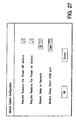
- the Access Control Card has the capability to count incoming rings and thereby permit actions based on the number of rings detected. If less and/or more than a user specified number of rings are received, the card may be configured to reboot the KEY-VIEW PC.
- the reset card monitors all incoming phone calls and can be configured to reboot the KEY-VIEW PC in the event less a user defined number of rings are detected or more than a user defined number of rings are detected.
- the modem When a modem is installed in the KEY-VIEW PC, it is possible that the modem answers a call but either the KEY-VIEW II and/or the remote access engine is locked up. In this case it will be necessary to remotely reboot the KEY-VIEW PC.
- the remote access engine can be configured to instruct the modem to answer a call only after four rings. Then, the KEY-VIEW II "Enable Reboot when less than "n" rings" is set to, for example, 2 rings. Using these settings, a remote user simply calls the KEY-VIEW PC and hangs up after one ring, thereby causing the KEY-VIEW PC to reboot.
- the Access Control Card also supports a variation of the "reboot on less rings" option where a touch tone code (up to eight digits) may be entered by a remote caller after the modem answers a call to cause the KEY-VIEW PC to reboot.
- a touch tone code up to eight digits
- a modem installed in the KEY-VIEW PC could lockup and hang onto a phone line, so that the line was always busy when a remote user attempts to access the KEY-VIEW PC.
- one remote user may wish to terminate another remote user's access during an emergency situation. Both of these situations can be resolved by connecting an external modem to the RJ-45 serial port of the Access Control card (using an optional connector and RJ-45 cable) and connecting a second (different) phone line to this modem. Any surplus external modem may be used for this purpose, since this modem will never operate above 2400 baud.
- the modem In cases where a NET-911 Control module is already connected to the Access Control Card's serial port, the modem should be connected to the "Data Out" port of the module. This modem would then be configured to be in an auto-answer mode. Then, the option to use an external modem must be enabled and a password defined, as discussed under the Enable Modem Reboot topic. In this situation, a remote user would simply use a terminal emulation program such as Hyperterminal (supplied with Windows) to call the external modem and enter the correct password when prompted by the access control card thereby causing the KEY-VIEW PC to reboot.
- a terminal emulation program such as Hyperterminal (supplied with Windows) to call the external modem and enter the correct password when prompted by the access control card thereby causing the KEY-VIEW PC to reboot.
- An Access Control Card also has the capability to issue pager alerts in the event a potential intruder is detected. Such pager alerts would be appropriate if a user fails to enter a correct password within a pre-specified number of guesses or a caller ID is detected from an unauthorized phone number.
- the person to be alerted via their pager and the related pager codes can be defined using the Pager Alert menu option.
- an optional external modem In order to issue a pager alert an optional external modem must be connected to the Access Control Card.
- the Access Control Card is also used to control the turbo light on the KEY-VIEW PC's front panel via a cable connected from the card to the KEY-VIEW PC's mother board's turbo light control pins.
- the turbo light is then used to visually indicate when a remote user was accessing the KEY-VIEW PC and to indicate whether the KEY-VIEW PC was in Host mode or a Menu mode.
- the KEY-VIEW PC's turbo light is OFF when the KEY-VIEW PC is in a Menu mode and is not being remotely accessed.
- the KEY-VIEW PC's turbo light will be ON when the KEY-VIEW PC is in a Host mode and is not being remotely accessed. This light will flash ON briefly whenever the KEY-VIEW PC is in a Menu mode and is being remotely accessed. If the KEY-VIEW PC is in a mode where both pcAnywhere is "In Session" and the KEY-VIEW PC is in a Host mode, the turbo light remains ON but then flashes OFF for .5 seconds every 5 seconds.
- the preferred embodiment of the present invention provides:
- the KEY-VIEW II Host Site consists of a KEY-VIEW PC connected to one or more Host PCs.
- a remote user can access an unlimited number of KEY-VIEW II Host sites using the remote access engine (preferably pcAnywhere).
- KEY-VIEW II is independent of the type of operating system running on the Host PC, since there is no KEY-VIEW II software running on the Host PC
- a typical preferred KEY-VIEW II PC has 4 PCI and 4 ISA slots and includes the following hardware components:
- a modem is typically used as a backup means to assure failsafe access to a KEY-VIEW II Host site in an emergency situation.
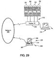
- Each KEY-VIEW II PCI card may be connected to either a Host PC directly or to multiple Host PC through a supported third party switch box. If a switch box is connected to the PCI card, the switch box must permit keyboard controlled switching between PCs connected to the switch box and deliver a consistent, high quality video signal to the PCI cards video input port. Most high end commercially available KVM switch boxes supplied by companies such as Cybex meet this criteria. In other embodiments, switch boxes are cascaded to one KEY-VIEW II.
- the video switch box used with the KEY-VIEW II employs switching between PCs accomplished using a standard IBM compatible keyboard connected to the switch box.
- the quality and stability of the switch box video output signal should be sufficient for KEY-VIEW PCI card to capture a clear, consistent video signal from the active Host PC.
- the KEY-VIEW PC includes three application software packages, namely pcAnywhere, NET-911 Control Module system and the KEY-VIEW II system. Preferably, no other software applications are installed or operated from the KEY-VIEW PC.
- a KEY-VIEW PC must be equipped with at least one means for remote access. It is recommended that two access modes be installed in case one of the means for remote access has failed.
- LAN access is then normally used as the preferred means for remote access because of the significantly faster response times. In the event the LAN fails then the remote access could occur via a modem or Internet connection.
- the Possible means for remote access to the KEY-VIEW II PC are as follows:
- the PCI slots are reserved for the KEY-VIEW II cards even if 4 cards are not initially installed in the system. Often users find they want to install additional KEY-VIEW PCI cards. Reserving the PCI slots for this purpose avoids the need to reconfigure the operating system if other PCI feature cards need to be changed to ISA cards.
- Each KEY-VIEW PCI card has the necessary Host PC VGA/SVGA analog to digital conversion hardware, Host PC keyboard interface, and Host PC mouse interface.
- One or more of these PCI cards may be inserted into the KEY-VIEW PC so that a single KEY-VIEW PC could control one or more Host PC's or PC switch boxes.
- PCI cards share the same addresses and IRQs.
- Each PCI card contains a 3 position DIP switch necessary to set the card ID from 0-7.
- each PCI card could optionally be connected to a supported switch box, which in turn may be connected to multiple PCs.
- a supported switch box can be remotely instructed to switch between Host PC's and pass the selected Host PC's keyboard, mouse, serial and video interfaces to the KEY-VIEW PC's PCI card.
- a switch box could be connected to 3 PC's where PC (1) is running a DOS text mode, PC (2) is running a 640x480 graphics mode and PC (3) is running a 1024x768 graphics mode.
- a remote user could click a menu option on the KEY-VIEW PC's screen to tell the switch box (via special keyboard key sequences) to switch from PC (2) to PC (3).
- Special unique KEY-VIEW II software interfaces to the operating system insures the KEY-VIEW PC automatically adjusts to different graphics modes on the fly, so that the KEY-VIEW PC's screen always mirrors the contents of a Host PC's screen on a full-screen basis.
- Each KEY-VIEW PC also requires one ISA KEY-VIEW Access Control Card.
- This card permits a remote user to reboot (via the Reset button's circuit) the KEY-VIEW PC in event the KEY-VIEW PC should ever lock up.
- An RJ-45 interface port is on this card that could be connected to an optional NET-911 Control Module to further permit cold booting (i.e. cutting AC power) to the KEY-VIEW PC from a remote location.
- this card may be used to control one of the status lights (normally the turbo light) on the front of the KEY-VIEW PC so that personnel at a Host site have a visible indication whenever someone is remotely accessing the KEY-VIEW PC (i.e. the light would be lit).
- any calls to a modem in the KEY-VIEW PC must first pass through the phone line interface IN/OUT ports on this card.
- This approach permits the card to capture the caller's ID (i.e. telephone number) from the phone line.
- the card could limit any remote user's modem access to the KEY-VIEW PC's as well as a remote user's KEY-VIEW PC reboot options based on the caller's ID. Accordingly, this call ID information can serve to increase the level of security and remote access to the KEY-VIEW PC.
- One of the standard serial ports of the KEY-VIEW PC is normally used to provide a serial interface to up to 250 NET-911 Control Modules. These modules may be daisy-chained together to permit a remote user to cold boot Host PCs or any other devices at a Host site. In addition, the modules also permit a remote user to serially access the device connected to the module, as if that that device were the only device directly connected to the Host PC's serial port.
- This feature is extremely useful by allowing the KEY-VIEW PC access to devices that can be remotely managed serially, such as routers, or as another avenue to permit file transfer to a Host PC.
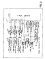
- the chief parts of the Key View II card are the FPGAs (Field Programmable Gate Arrays) and the on-board CPUs.
- the card has three main functions : the video capture circuit, the keyboard/mouse circuit, and the serial port circuit.
- the card is designed to interface with a PCI bus architecture.
- the card is primarily designed around two FPGAs, preferably, of the Xilinx XC3100A family, which operate over 80 MHz.
- the other is the main FPGA and is a standard Xilinx part.
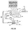
- the FPGA 11 is surrounded by several different circuits. These include the video interface circuitry 14, the serial controller chip circuitry 15, mouse and keyboard driver circuits 17 and 18, the keyboard and main card CPU circuits 20 and 21, the dock 19, the flash palette converter RAM 24, the video capture RAM 25 and 26, and the PCI bus controller chip 22 communicating with PCI Bus 23. Card ID switch 16 is also included.
- FIG. 2 illustrates the video interface circuitry 14 to the FPGA 11.
- Three sets of video buffer circuits 29-31 contain video amplifiers that boost the video and send it back out to the VGA display. These circuits 29-31 also provide noise and level conditioning to accommodate the ADCs 32-34, which expect the analog signals to be within the bounds of known voltages.
- the analog color signals drive three Analog Devices AD9O12 flash analog to digital converters 32-34. These circuits convert the input voltage to an output 8 bit digital value using flash conversion technology whereby the reference signal is divided by an internal resistor voltage ladder into 256 individual steps. These voltage steps are simultaneously compared to the input signal by 256 separate analog comparators. By comparing all possible values at once, the chip can operate at up to 100 MHz.
- the ADC chips output 8 bits the PCI card requires only 5 bits for each color. Thus, the 3 least significant bits are discarded yielding 15 address bits.
- the combination of the Flash Palette Converter RAM discussed below and the process of discarding the three least significant bits of the video signal make the captured video extremely stable.
- the sync pulses, Hsync and Vsync, from the video signal are conditioned and fed into the main FPGA 11. Both of these signals are polarity coded so that older monitors (non-multisync) will know what mode the VGA card was sending. This means that the signals might either be negative or positive pulses. Since TTL level signals are needed for the FPGA, these random polarity signals must be converted to positive TTL level signals. But before that is done, the polarity itself needs to be converted to a TTL level signal and also fed into the FPGA. Therefore, the sync conditioning circuits 35 and 37 will output four TTL lines - two sync pulses and two polarity pulses. The FPGA will latch the polarity pulses internally to form two stable polarity bits (see FPGA registers).
- the FPGA also does some additional processing of the video sync pulses. Because the software needs to know the exact video frame rate, the FPGA has a small frequency counter that counts the number of Vsync pulses in a second and stores that value in an FPGA register. Another FPGA counter counts the number of Hsync pulses in between Vsync pulses. This value is also stored in another FPGA register.
- the Hsync pulse is fed to conditioner 36 and PLL 38.
- Some video cards will blank this signal after the end of active video. For physical monitors, this is not a problem; however, for PLL circuits, it can cause the output frequency to drift. Most PLL circuits require a stable reference frequency or else they will become unstable. Some PLL chips, such as 1C51522 PLL chip, have the necessary circuitry to ignore the missing Hsync pulses.
- the output of the PLL becomes the dot clock for the video. Each pulse from this dot clock should line up exactly with the center of each dot on the video signal. Therefore, the PLL includes a method for adjusting the phase of the output dot clock and for supporting the various number of video line lengths, i.e. 640, 800, 1024, etc.
- the Keyview PCI card uses two separate CPUs for embedded processing, the main CPU 21 and keyboard CPU 20.
- the keyboard CPU interface has no external memory so most of its I/O pins are free to do other things.
- Two ports of the keyboard CPU are used to control the two mice and the keyboard and the other ports 0 and 2 are used to communicate with the main CPU and serial EEPROM.
- the interface of the main CPU 21 to the card includes external program RAM memory 41 holding some program code for the microprocessors.
- the instruction fetch and data read/write signals from the CPU are merged by logic in the FPGA to allow the CPU to execute code from the RAM.
- the RAM is mapped to the last 32K of the CPU's address space. This guarantees that the bootstrap program that is in the EPROM inside the CPU will receive control on reset before the RAM does. Using software techniques, the actual program is loaded into the RAM by the bootstrap program. With this done, control is transferred to the program in the RAM after IPL.
- the main CPU 21 is also capable of addressing the FPGA registers 11 and both of the Dual Port Flash Palette Converter RAMs 24A and 24B. These are all mapped into the first 32K of the data storage space of the main CPU. This is possible since the CPU treats data memory differently than program memory. To prevent conflicts between the FPGA registers and the Flash Palette Converter RAMs (which are all mapped to the same location and bank), two special device select bits are output directly from the main CPU. These I/O lines select the device that will be addressed when the CPU accesses the lower 32K of its data memory address space.
- the main card CPU 21 has a watchdog feature that will reset the CPU if it does not respond to it within a certain amount of time.
- the keyboard CPU 20 does not have any such automatic circuitry. Instead, the reset line to the keyboard circuit is controlled by the main card CPU directly. This keeps the main CPU from locking up indefinitely.
- the address latch is, in practice, usually an external 74L5373 or equivalent. Because the inputs to this chip are needed by the FPGA 11 to access the FPGA registers, this latch function is implemented in the FPGA.
- the ALE is input to the FPGA latch strobe and, in response, the Q outputs of the latch are output. Using this configuration, up to 256 individual registers may be addressed inside the FPGA.
- the CPUs are two 87C52-24 microprocessors running parallel in a master/slave arrangement from the main and keyboard CPUs 20 and 21. They will both run from the same 22.1184 Mhz clock supplied by the keyboard circuit.
- the main card CPU 21 sends commands and data to the keyboard CPU in a serial fashion.
- the keyboard CPU 20 will have a program that simply sends codes to the keyboard and mouse as it is told to do so by the main CPU 21.
- the main card CPU 21 has bootstrap code which controls its IPL.
- the main program is housed in RAM and has a jump table at a fixed address so that whatever program is running will know how to call the library functions. This way, many of the library functions can be incorporated into the extra space of the EPROM and then overwritten if they become obsolete.
- the inter-CPU communication routines can be shared between the keyboard CPU program segment and the main card CPU program segment.
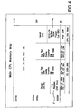
- the main memory map is shown in Figure 4. Rather than keeping the RAM (data) and ROM (code) address spaces separate, in this design, a RAM program storage area is needed to facilitate program uploading, meaning that the RAM chip is mapped to both the RAM and the ROM areas of the upper 32K of each address space.
- a bootstrap program is burned into the internal EPROM 45. It is 8K in length and is mapped starting at ROM address OQOQH and cannot be accessed using RAM reads. On power up, the bootstrap code will have control.
- the KV-APP will load the main card CPU's RAM with it's program, called an IPL (Initial Program Load).
- the RAM is mapped to 000H-FFFFH in both RAM and ROM address spaces 46 of the main card CPU.
- the RAM is a 32Kx8 1 5ns chip or better.
- the program in the keyboard CPU is fixed and cannot be overwritten by the KV-APP.
- the CPU's can be mask programmed, OTP programmed, or EPROM programmed. It is important that the security bits on the CPU not be set in a way that would prevent external code from executing.
- an Intel 87C52BH series microprocessor may be used. It is highly likely that both the keyboard and the main card IPL code will be combined into the same EPROM program space.
- the CPU would determine if there is any external RAM attached to it. If so, the device will run the main card CPU code. If not, the device will assume the personality of the keyboard CPU.
- the keyboard process is allocated 25% of the total EPROM space and the main process is allocated 75%. In the currently selected 87C52-24 chip there is 8K of EPROM which translates to 2K for the keyboard process and 6K for the main process.
- the KV-APP will instruct the main card CPU to begin executing the RAM program.
- the RAM program contains extra code and functionality that the bootstrap program does not.
- the serial lines (Clock, Data, and RD/WR [P1.0]) are bussed to all the serial devices.
- the CPU 21 also outputs individual device select lines for each device.
- the serial devices ignore their inputs (clock, data, and RD/WR) until they receive a high level on their device select (CS) input. No device is allowed to output any signal until it is selected and must change all of it's outputs to a high impedance state when it is not selected.
- the PLL 38 is a special case. With it, the RD/WR pin is not used, and the Read/Write function is incorporated into the data stream.
- the keyboard CPU has a private EEPROM chip attached to it so the keyboard circuit can access the EEPROM data while the remainder of the circuit is powered down.
- the keyboard CPU must be accessed serially. It does not have any registers that are directly accessible, but uses a command approach instead. With this approach, the number of bytes to and from the device are variable depending on which command is executed. The first byte that is written to the keyboard CPU is the COMMAND byte.
- Some example commands include: CODE COMMAND Action 00000000 NOP No Operation 01000000 RESET Reset the keyboard CPU error flag 00000100 QUERY STATUS Copy the status register to the output register 01000100 READ FIFO Copy the top FIFO byte to the output register 00000001 MOUSE TYPE Change the mouse hardware type (next byte) 01000001 SEND KEY Send a byte to the keyboard (next byte) 10000001 SEND MOUSE Send a byte to the mouse (next byte) 11111101 READ PROM Move an EEPROM byte to the output register 11111000 ENABLE WRITE Enable a WRITE PROM as next command 11111010 WRITE PROM Writes a byte to the EEPROM
- All read operations on the keyboard CPU 20 will read the contents of the CPU 20 output register. This register is set by certain commands and may be read multiple times without affecting its contents.
- the lower three bits of the keyboard command codes have a special meaning.
- the two LSBs (bits 1 and 0) always indicate the number of bytes that will follow the command byte. This configuration allows for up to three bytes to follow the command byte. If bit 2 is set, then the command will alter the contents of the keyboard CPU's output register. The remaining bits are arbitrary and serve only to make each command unique.
- the WRITE ENABLE condition is voided. Any attempt to send a WRITE PROM command without first sending a WRITE ENABLE command will cause the keyboard CPU to ignore the WRITE PROM command and set the appropriate error flag in the keyboard status register. The requirement of a preceding WRITE ENABLE command before a WRITE PROM command will help prevent inadvertent EEPROM writes by confused microprocessors.
- the keyboard CPU software resets the serial interface so that if the last byte was sent in error, it will be cleared.
- the keyboard CPU is written to when the RD/WR' pin is low and read when the RD/WR' pin is high.
- the status register that is returned for a QUERY STATUS command has the following definitions:
- the main CPU 21 has several I/O pins that are dedicated to communication with the keyboard CPU 20.
- One I/O pin is a special BUSY input pin that is fed directly by the keyboard CPU. This indicates to the main card CPU that the keyboard CPU is busy with something and cannot respond to serial input. When the keyboard CPU is idle, it will clear the BUSY output.
- Another I/O pin of the main CPU is connected to the RST (Reset) input of the keyboard CPU circuit. This allows the main CPU to reset the keyboard CPU when the keyboard CPU loses control. Special circuitry is also in place to allow the keyboard CPU to reset itself on power up and to prevent accidental resets when the main CPU is powered down.
- a third input I/O pin on the main CPU is fed by the keyboard's RTS (Ready To Send) output. This output tells the main CPU that the keyboard's internal FIFO has something in it and that it needs to be serviced.
- a handshaking approach is used.
- the main CPU wants to send a byte to the keyboard CPU, it first checks the BUSY input from the keyboard CPU to make sure that it is low. If it is high, the main CPU must wait for it to clear. If the main CPU has to wait longer than one second, it will assume that the keyboard CPU has crashed and will reset it by toggling the RST pin on the keyboard CPU. Otherwise, with the BUSY input low, the main CPU can begin transferring a serial byte.
- the BUSY flag also indicates to the main CPU that the keyboard CPU has finished processing a serial input bit. This status is triggered by the device select input. Therefore it is important to read the BUSY pin before selecting the keyboard CPU.
- the main CPU 21 Before the main CPU 21 sends the first bit, it first sets the serial clock and RD/WR' lines low and sets the keyboard device select line high. It then outputs the data bit on the serial data line. With this done, it changes the level of the clock output to high. When the keyboard CPU sees a low to high transition on the serial clock line, it reads the bit on the serial data line. Then, when the keyboard CPU 20 has finished processing the bit, it pulls its BUSY output high. This tells the main CPU that the bit was received and processed. The main CPU then pulls the serial clock back low which signals the keyboard CPU to do the same with it's BUSY output. This process continues until all eight bits of the byte are transferred from the main CPU to the keyboard CPU. When all of the command bytes have been transferred, the device select line is cleared and the keyboard BUSY output returns to normal use. This procedure enables the keyboard CPU to detect serial framing errors while maintaining a high data transfer rate.
- a similar process takes place when the main CPU reads a serial byte from the keyboard CPU's output register.
- the main CPU sets the clock line low and the RD/WR' and device select lines high. This time, when the main CPU pulls the clock line high, the keyboard CPU will output a bit on the serial data line. With this done, the keyboard CPU then pulls it's BUSY output high. This tells the main CPU that the data is ready to be read. When the main CPU has read and finished processing the input bit, it pulls the serial clock line back low. The keyboard CPU sees this and does the same with its BUSY output. Again, the process continues until the entire byte is sent from the keyboard CPU to the main CPU. Since there is only one byte to read, the device select line is reset. Keyboard Command Procedure
- Typical keyboard operation for sending scan codes to the host is for the main card CPU to issue the following commands to the keyboard CPU:
- the keyboard CPU Upon receiving the scan code byte, the keyboard CPU temporarily sets its BUSY pin and sends the byte verbatim to the host.
- the ERROR flag in the status register is set if the keyboard CPU is asked to process a command that is not valid. This error detection applies only to keyboard CPU commands and not to scan code data.
- switch box will return invalid scan codes as a form of communication. These are added to a 16 byte software FIFO inside the keyboard CPU upon receipt. This FIFO is actually implemented as a circular queue. Since the switch boxes would normally never send more than 4 bytes in response to a key sequence, there is only a remote possibility that the 16 byte FIFO would be overrun before it could be serviced by the main card CPU. The sequence would be something like this (for a [NUMLOCK][MINUS] [NUMLOCK] key sequence):
- the PLL 38 video dot clock chip requires special serial access.
- One main difference is that the RD/WR' pin for all the other devices is not used.
- the PLL gets this bit via the data stream.
- the device select output from the main CPU is connected to the SELn input pin of the PLL chip.
- the PLL 38 uses a RD/WR bit, followed by a three bit address, followed by an eleven bit data byte.
- a 4-wire serial EEPROM is provided on the card for nonvolatile data storage.
- An example design calls for a 2K serial EEPROM organized as 256 x 8 bytes.
- the EEPROM stores the External Serial Port IRQ and Base addresses when the KeyView computer is powered down.
- the EEPROM is local to the keyboard CPU 20 and be powered by the dual power supply of the keyboard circuit.
- the main card CPU 21 can access the information in the EEPROM by querying the keyboard CPU.
- the EEPROM is not on the serial bus and the main CPU cannot access it directly.
- the watchdog timer circuit for the main CPU 21 is incorporated into the main CPU IC.
- the keyboard CPU 20 has a software driven watchdog circuit built into the main CPU. If the keyboard does not respond to a command that the main CPU sends it within a finite amount of time, then the main CPU will toggle the keyboard CPU's RST line. This will cause the keyboard CPU to reset.
- Both CPUs have special circuitry to enable power up reset and other circuitry to prevent inadvertent resets of the keyboard CPU when the main CPU is not powered up.
- the main FPGA which is the only one that contains registers, is mapped into the main card CPU's RAM space ( Figure 4).
- the first 256 bytes of RAM space 47 (OOH to FFH) correspond exactly to the FPGA register space. It is important that the FPGA device select be set high for all FPGA register accesses. If not, CPU accesses to RAM locations in the OOOOH to 7FFFH region will be mapped to the Flash Palette Converter RAM. However, when the FPGA device select bit is set high, the contents of the FPGA registers can be read from and written to directly.
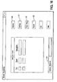
- the main CPU 21 has eight identified Port 1 connections (P1.0-P1.7) shown in Figure 3, and discussed as follows:
- the design may include several FPGAs 11 from a hardware standpoint, even though from the software standpoint, all of the registers are in a single FPGA.
- a second FPGA needs register information it will be necessary for it to have a hardware connection to the first FPGA in order to gain access to the registers.
- the registers are addressed directly by the main CPU 21 and there can be potentially up to 256 registers in each FPGA. Before the main CPU can address any of these registers it must first output a high level on the FPGA Device Select output pin P1.1. This enables the FPGA registers and disables the Flash Palette Converter RAM.
- some registers include: 00 - This is a null register and returns random values when read or written. 01 - FPGA Flags - This byte is read only and the contents of this register are set by the FPGA. Bit 1 is imported from the video FPGA. The flags in this register are:
- the card 10 does not contain any knowledge of which I/O base address is supposed to actually be the command port. Without the I/O base address, there is no way for it to receive commands from the KV-APP. To get around this, a small self-training procedure has been developed. In this procedure, the KV-APP selects one I/O base address out of a possible 8 that the card will be using. It will then send a NOP (code 00) addressed to card 0 to this address repeatedly. These NOP's are sent in 1/10th second intervals for up to ten seconds. If the card is present, it will latch on to the I/O base address and decloak. This function is part of the software and not the FPGA. All cards are in stealth mode during this phase of the initialization or else bus conflicts will occur.
- the KV-APP then confirms the card's presence by reading the command/ status register and the three parameter ports.
- Decloaking is not the normal operation for the NOP command and should not be used to tell the card to decloak. Normally, the NOP command simply does nothing except clear the status register to zero. With the first card properly loaded with the correct I/O base address, the KV-APP then repeats the procedure for all four PCI cards in the Keyview PC. Before proceeding to the next card, the decloaked card is put back into stealth mode (cloaked). During initialization, the code that processes the NOP instruction will be located in the EPROM IPL code. After the main card CPU software is loaded, the old NOP processing code is overwritten by the new code in the RAM.
- Some of the commands to the KeyView II card require multiple parameters. The parameters are first loaded into the parameter port registers and then into the command register. This is because the card will take action on the command as soon as it is written and will not wait for the parameters to be written. The order in which non-packeted parameters are written is not important as long as the command register is written last.
- the transfer of packets to the KV-CARD 10 is fairly straightforward.
- the code for the device or internal buffer that is to receive the packet is first written into parameter port 0.
- the file that is to be sent to the card is divided into 256 byte chunks.
- the 'chunk' number (starting at zero) is loaded into parameter port 1 with the high bit set. Setting the high bit indicates that it is writing and not reading.
- the 8 bit checksum of the 256 byte packet will be sent as the 257th byte of data, so the CPU on the card can verify a valid transfer.
- the first byte of the packet is written to parameter port 2. Writing all of these registers does nothing by itself, however, when the "TRANSFER PACKET" command is written to the command register by the KV-APP, the transfer process begins.
- the first thing that happens during a packet transfer command is that the first byte in parameter port 2 is loaded and saved into a temporary buffer. Because writing to the command or parameter ports by the KV-APP causes the FPGA to automatically set the busy flag for that register, the CPU will have to clear the busy flag for parameter port 2 when it is finished processing each byte.
- the KV-APP detects this and writes the second byte of the packet to this port. With that done, the KV-APP waits until the busy flag is clear again. It then sends the next byte, and so on, until all 256 bytes have been transferred. The 8 bit checksum is then sent as the 257th byte. At that time, the main card CPU compares the checksum with the actual checksum of the received packet. If the two are different, the CPU reports this by setting the ERROR flag in the status register. On error, the contents of the temporary buffer are discarded.
- the contents of the temporary buffer is copied to the device or location that was initially referenced by the value written to parameter port 0 and at the address specified in parameter port 1.
- the BUSY flag for the command register remains set until the packet transfer is complete. All command and parameter port busy flags are cleared when the packet operation is complete.
- the 'chunk' (packet) number that was loaded into parameter port 1 is only used when transferring data to and from the CPU RAM 41 and the flash palette converter RAMs 24A and 24B. With single packet transfers, the high bit is still important, and the packet number should be set to zero. The checksum is valid for all transfers. It should also be noted that if any other command is written to the command register during a packet transfer, even a NOP, the entire packet is discarded.
- each 256 byte packet is sent separately as a separate command. In these cases, it is important to specify which 256 byte packet is being transferred. Only one of 128 packets (32K) may be specified in parameter port 1 to any given device. These packets do not have to be in sequential order.
- the address of the device or internal buffer that the packets are to be read from is first written into parameter port 0.
- the index number of the packet that is to be read is loaded into parameter port 1 with the high bit clear. For everything except the RAM devices, this will simply be zero. Clearing the high bit indicates that it is reading and not writing.
- a zero is written into parameter port 2 in order to force the FPGA to set the busy flag for parameter port 2.
- the card will first send the 256 bytes of the packet and then the checksum byte, so the CPU on the card can verify a valid transfer. Writing all of these registers does nothing by itself, however, when the "TRANSFER PACKET" command is written to the command register by the KV-APP, the transfer process begins.
- the main card CPU writes the first byte in the packet to parameter port 2. Then it clears the busy flag for that port.
- the KV-APP detects that the busy flag for parameter port 2 is no longer set, it reads the port and stores the first byte of the packet.
- the FPGA automatically sets the busy flag for the port when the KV-APP reads it. This prevents the KV-APP program from reading the same byte multiple times.
- the main card CPU places the second byte of the packet in parameter port 2 and clears its busy flag.
- the KV-APP then reads and stores that byte also. This process continues until all 256 bytes have been read by the KV-APP. At that time, the main card CPU transfers a 257th byte which is the checksum.
- the KV-APP always makes a point of reading the checksum byte even if it does not use it.
- the BUSY flag for the command register remains set until the packet transfer is complete. All command and parameter port busy flags are cleared when the packet operation is complete.
- the packet number that was loaded into parameter port 1 is only used when transferring data to and from a RAM device. For all other devices, this is set to zero. The checksum is valid for all transfers. If any other command is written to the command register during a packet transfer, even a NOP, the packet transfer is terminated and may leave the KV-APP in an unspecified state.
- each 256 byte packet is sent separately as a separate command. In these cases, it is important to specify which 256 byte packet is being transferred. Only one of 128 packets (32K total) may be specified for any given device. These packets do not have to be in sequential order.
- This command has the effect of clearing the busy and error flags in the status register.
- the busy flags are always cleared when the command completes. Since a NOP doesn't do anything in particular, it is always complete and thus clears all four busy flags.
- the first 6 bits of the command byte are all zero and the last two, bits 6 and 7, are for card addressing. Only the card that is actually addressed will process the NOP instruction. This is regardless of whether or not the card was in stealth mode.
- This command provides the capability to cloak, decloak, turn off, and turn on the cards in the system.
- the actual function of this command is prescribed by the value present in Parameter port 0.
- This command allows 256 byte packets to be transferred to and from the KV-APP.
- the device or buffer that the data comes from or goes into is specified by the DEVICE parameter which is loaded into Parameter port 0 before calling this command.
- the address of the packet in the card device can be specified in cases where there are multiple packets. This includes the main card CPU program and the flash palette converter RAM contents.
- the address byte is stored in Parameter port 1. It is actually only 7 bits so that the range of values for the address is limited to 0 to 127. Since this is actually an index to 256 byte pages, it can actually address from 0 to 32,768.
- the CPU RAM is addressed relative to the beginning of the device and not to the actual CPU address.
- Bit 7 of the address byte controls this. If bit 7 it set, the operation is a packet WRITE to the card. If bit 7 is clear, the operation is a packet READ from the card.
- Parameter port 2 is where all the data is read or written to. The 256 bytes are transferred sequentially until all have been sent. After this, an additional one byte checksum is also sent.
- This command causes the Main Card CPU to mathematically generate a uniform palette and load it into the flash palette converter RAM.
- the actual palette generated depends on the contents of parameter ports 0 and 1. If parameter port 0 is zero, the palette will be Black & White Greyscale. If there is any other value in parameter port 0, then the palette will be color.
- Parameter port 1 contains the total number of colors to generate in the palette. The only available options for the number of colors are 0 (2 color), 1 (4 color), 2 (16 color), and 3 (256 color). Only the lower two bits of parameter port 1 are considered.
- Parameter port 0 defines the device to access. These are the same as for the serial addressing section: Param 0* Device Param 1 0 Main FPGA regs Register number 1 Keyboard CPU Keyboard CPU command 2 ICS 1522 chip Register Number 3 Keyboard reset Don't care (write only) 4-127 None Don't Care * Only the first two bits are valid device select bits. Bit 7 is a Read/Write bit. All other bits of parameter port 0 are ignored.
- Parameter port 2 is where the data is returned for read operations and entered for write operations. For read operations, the data in parameter port 2 is valid when the busy status flag is reset.
- the EEPROM is accessed through keyboard commands.
- the keyboard interface can also require multiple bytes. Since this command can only send one byte at a time, multiple calls to the keyboard may be necessary in order to fully access it. Keyboard reads will always return the keyboard output register.
- the ICS 1 522 chip uses 11 bit registers instead of the usual 8, only the lower 8 bits are returned or set. To access the upper 3 bits of the register, 32 is added to the register number before invoking this command.
- All video modes are divided into 32K segments. Each one of these segments has a checksum associated with it. There can be up to 64 of these segments in the 1280x1 024 resolution.
- the main card CPU stores the checksums in its RAM memory.
- the TRANSFER command is the only way that the KV-APP can write to the checksum registers.
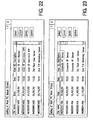
- Mode 2 color 4 color 16 color 256 color 320x200 1 (200) 1 (200) 1 (200) 2(100) 640x200 1 (200) 1 (200) 2 (100) 4(50) 640x350 1 (350) 2 (175) 5 (70) 7 (50) 640x400 1 (400) 2 (200) 4 (100) 8 (50) 640x480 2 (240) 3 (160) 5 (96) 10 (48) 800x600 2 (300) 4 (150) 8 (75) 15 (40) 1024x768 3 (256) 6 (128) 12 (64) 24 (32) 1056x350 2 (175) 5 (70) 7 (50) 14 (25) 1056x400 2 (200) 4 (100) 8 (50) 16 (25) 1280x1024 8(128) 16(64) 32(32) 64(16)
- This command sends the mouse mickey information.
- the X-mickeys are written to parameter port 1 and the Y-mickeys are sent to parameter port 2.
- This command sets the base port and IRQ of the 8250 serial port controller.
- the IRQ is written to parameter port 0 and the base port address is written to parameter ports 1 and 2.
- the MSB is in parameter port 1 and the LSB is in parameter port 2. If all of the parameter ports are zero, then the 8250 chip will be disabled without affecting the actual IRQ and base port address. If all of the parameter ports are 255, then the current values of the serial port are returned without changing them.
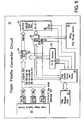
- this design uses a flash palette converter 52, shown in Figure 5.
- This circuit uses a simple hardware circuit to convert RGB 5-5-5 color inputs directly to a palette index. The circuit will allow the main card CPU 21 to program the Flash Palette Converter RAM 24 with values on the fly so that the video mode can be changed. It should be noted that the palette index that is output by this circuit is not a color value and has no direct correlation to color or luminance. It is simply an index that is used by the VGA card to look up the preprogrammed color values. Computations and comparisons on the palette index value will not necessarily yield meaningful results.
- the output from the video capture circuit 53 is digital video in RGB 8-8-8 format. Because the Flash Palette Converter RAM 24 has only 15 address inputs, the three least significant bits of each color are discarded to form video in RGB 5-5-5 format.
- the address and data lines of the Flash Palette Converter RAM are both fed by way of two multiplexers 54 and 55.
- the address multiplexer 54 is a simple, unidirectional multiplexer that will handle all 15 address bits.
- the multiplexer has two input selections and one output. The data going through the address multiplexer travels in only one direction regardless of which input bank is selected. There are two possible input banks to the address multiplexer.
- the select input to the multiplexer will switch between the RGB 5-5-5 signals for normal operation and the output of a 15 bit counter for program mode.
- the data multiplexer 55 is a little more complicated. During normal operation, the data signals coming from the I/O pins on the Flash Palette Converter RAM 24 are output only and are sent to the Pixel Storage Circuit 56. The data flow is one way only in normal operation mode. However, in program mode, the data flow is bidirectional. In program mode, the multiplexer 55 makes a bidirectional data connection between the FPC RAM 24 and the FPGA data register 57 that contains the byte to write to it. Thus, in program mode, the RAM contents can be both read and written. The reason for allowing the data to be read out in program mode is for self-diagnostic purposes.
- the Flash Palette Converter timing circuit 58 generates the various control signals that are needed throughout the FPC circuit. These signals include RD/WR' and CS' of the RAM 24, CLR and CLK of the address counter 59, and the two SEL lines to the multiplexers 54 and 55. It will use the FPGA registers 57 and the pixel clock as input. The pixel clock is needed during normal operation to ensure that the RAM reads are timed properly. In program mode, the pixel clock is not used.
- the SEL lines to the multiplexers are connected to the flag in the FPGA registers that control the operation of the SEL signal.
- the CLR signal to the address counter is done the same way.
- both the SEL and CLR lines are directly connected to a bit in the FPGA registers, they will account for a minimal portion of logic in this circuit.
- the data lines from the data multiplexer are connected directly to the FPGA register. This register can be accessed directly by the Main Card CPU 21 as though it were RAM memory.
- the RD/WR' input to the FPC RAM is held high while the CS' input is connected to pixel clock.
- the pixel clock is conditioned in such a way as to account for propagation delay and RAM access times. This signal is also passed on to the Pixel Assembly Circuit.
- the address to the FPC RAM is supplied by the 15 bit counter. This counter is cleared to zero under CPU control by toggling the FPGA register flag that corresponds to the CLR pin on the counter. The counter is then incremented by the FPC timing circuit following READ and WRITE operations by the CPU to/from the FPGA data register.
- a standard clock (FPGA CLK) reference will be necessary for program operation.
- the pixel clock (PIXEL CLK) cannot be used because there is no guarantee that it will exist, nor is its frequency well established.
- the standard FPGA clock is therefore used for generating timing patterns when in program mode.
- the Address Clock signal occurs after the RAM Rd/Wr' signal.
- the Address Clock (Addr CLK) is the pulse that is used to advance the 15 bit address counter 59 during programming.
- the CPU RD' and CPU WR' signals are random in length, therefore, the Address Clock signal will not rise until the CPU signal has returned high. When that happens, the Address Clock signal will rise for exactly one FPGA clock cycle.
- the ALE strobe from the main card CPU 21 as the clock source for program mode.
- the very next ALE pulse after the conclusion of the RD' or WR' strobe (and only that pulse) can be used directly as the Address clock pulse. Care in designing any circuits that use the ALE should be taken so that there is no direct connection to the Address Counter. If that were to happen, the main card CPU would not be able to correctly read or write to the FPC RAM. The main point is that the Address Counter is incremented only after a byte is read or written to the FPC RAM.
- the purpose of the Pixel Assembly Circuit 75 ( Figure 8) is to compact up to eight pixels into a single byte for storage, as shown for example in Figure 7.
- the number of pixels that will fit in a byte depend on the number of bits per pixel of the particular color mode in use. There is a direct correlation between the number of bits per pixel and the number of possible colors. There will not be a situation where there are pixels of different sizes stored in the same byte.
- one bit per pixel mode 70 there are only two possible colors and eight pixels are stored in a single byte. Because there are only two possible colors, this mode can only be used for monochrome screens.
- the colors used in two color mode do not necessarily have to be black and white, but could be any two colors.
- the original captured screens can be any number of colors. The action of the Flash Palette Converter will automatically select one of the two colors that is closest.
- two bits per pixel mode 71 there are four possible colors and four pixels are stored in a single byte. Because there are only four possible colors, this mode is on the borderline of reasonable color. Some text screens, such as those designed for CGA monitors, have only four colors to capture. However, in practice, the two bit mode is best suited for four level grayscale. Again, it makes no difference how many original captured colors exist on the host. The Flash Palette Converter will automatically approximate each color into the appropriate gray level.
- the action of the Pixel Assembly Circuit 75 of Figure 8 is to pack the pixels into a byte that will be stored in the video RAM and eventually sent across the bus 23 to the PCI APP.
- 256 color mode all eight bits are used so for that mode, the Pixel Assembly circuit simply passes through the byte.
- the Pixel Assembly Circuit In all other modes, the Pixel Assembly Circuit must assemble a byte from fragments of up to eight pixels.
- the output byte from the Flash Palette Converter RAM 24 is applied to a special eight bit register.
- This register is really a latch composed of eight, independently controlled D-type flip-flops 78. With this configuration, each bit on the input side can be selectively loaded into the register.
- the Sum-of-Products (SOP) logic array 77 controls which bits are loaded and when the inputs to the SOP circuit 77 are the color mode and a three bit counter.
- the color mode is as previously defined and is used by the SOP logic array 77 compute the number of pixels that are loaded into a single byte.
- a value of '00' represents one bit per pixel mode (2 colors).
- a value of '01' represents two bits per pixel mode (4 colors).
- a value of '10' represents four bits per pixel (16 colors).
- a value of '11' represents eight bits per pixel (256 colors). This value is obtained directly from the appropriate FPGA register.
- the three bit counter 76 is provided so that the SOP logic array 77 knows which part of the byte to load. In 256 color mode, all eight bits are used so the counter is ignored. In 16 color mode, only the lsb of the counter is used. Likewise, with 4 color mode, only the two 1sb's of the counter are used. However, in 2 color mode, all three bits of the counter are used. The SOP logic array automatically decides how many bits of the counter to consider. Therefore, there is no need for additional circuitry to modify the number of counter output bits.
- the CLK strobe to the three bit counter 76 is connected to the Byte Ready Strobe from the Flash Palette Converter circuit 52. This pulse is used to increment the counter once for each pixel that comes in.
- the CLR strobe to the three bit counter 76 is derived from the Hsync pulse.
- the purpose of this arrangement is to ensure that the counter will be zero for the first pixel on each horizontal line. It might not be possible to use a raw Hsync pulse, but the signal that clears the counter can be derived from it by using the appropriate gates.
- the pixel byte from the Flash Palette Converter RAM 24 is presented to the inputs of the eight flip-flops 78.
- the SOP logic array 77 will signal the flip-flop in the DO position to load, and no others.
- the next pixel byte comes in only the flip-flop in the D1 position will be loaded, and no others. This continues until the eighth pixel byte comes in and is loaded into the D7 position.
- D7 clock strobe also functions as the Byte Ready Strobe for the next circuit.
- DO and D1 are loaded from the first pixel byte from the Flash Palette Converter RAM 24. Then D2 and D3 are loaded next, then D4 and D5, and then finally D6 and D7.
- the X and Y variables correspond to the two bit color mode from the appropriate FPGA register.
- the X is the least significant bit and the Y is the most significant bit.
- the color modes are "00" for 2 color mode, "01” for 4 color mode, "10” for 16 color mode, and "11” for 256 color mode.
- the A, B, and C variables are the output of the 3 bit counter. A is the least significant and the C is most significant.
- Out ⁇ 0 ⁇ m 0 ⁇ 8 ⁇ 12 ⁇ 16 ⁇ 18 ⁇ 20 ⁇ 22 ⁇ 24 ⁇ 25 ⁇ 26 ⁇ 27 ⁇ 28 ⁇ 29 ⁇ 30 ⁇ 31
- Out ⁇ 0 XY + A ⁇ Y + A ⁇ B ⁇ X + A ⁇ B ⁇ C ⁇
- Out ⁇ 1 ⁇ m 1 ⁇ 8 ⁇ 12 ⁇ 16 ⁇ 18 ⁇ 20 ⁇ 22 ⁇ 24 ⁇ 25 ⁇ 26 ⁇ 27 ⁇ 28 ⁇ 29 ⁇ 30 ⁇ 31
- FPGA designs speak in terms of logic cells and not gates. In reality, since the logic cells include the above gates as well as flip flops, only 8 logic cells are required for this design. The three bit counter will add another three logic cells. Therefore, the total circuit requires only 11 logic cells.
- the 32x8 SRAM approach requires wait states even if very fast 5ns SRAMs are used.
- the reason for this assumption is that the FPGA would have to operate at over 200MHz in order to make the four 8 bit reads, concatenate them into a single 32 bit word, and present them on the PCI bus. Since the FPGA/PCI MASTER only operates at around 100 MHz, this means that there could be as many as four wait states per 32 bit word transfer. This would choke data transfer speeds and would not be acceptable. Instead, it is better to keep the video storage at 32 bits for the present embodiment.
- a speed of 12ns or faster should be acceptable.
- the SRAM may have "Byte Write” capability (an example of such is Cypress CY7C1337).
- Cypress CY7C1337 This alternative allows the use of an 8 bit Pixel Assembly Circuit (thus reducing the number of gates) while still presenting a full 32 bits to the PCI bus. Since there are 4 write strobes on the RAM (one for each byte), a simple cyclic 4 bit counter can be used to load the byte into the proper location of the 32 bit word.
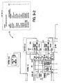
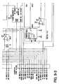
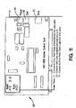
- FIG. 9 A detailed diagram of the Keyview II example embodiment Expansion Card is shown in Figure 9.
- the attached Figure 9 is not to be interpreted as an exclusive schematic for the expansion card but only as a general block diagram description for the functionality of the Keyview II Product.
- the block diagram is divided into fifteen separate sections as identified by the broken line enclosures for each block. All I/O's for the Keyview II card (“KV card”) is through three connectors, i.e., the VGA DB-15, the Cybex 44-pin, and the PCI plug-in connector located at the bottom of the expansion card. Input power for the card (+5VDC) is derived from the PCI motherboard of a standard PC, through the PCI connector.
- Section 1.0 of Figure 9 is the power supply circuit. Because the KV card requires a negative -5VDC rail which is used in the input video section of the card, it is necessary to derive the negative voltage from the standard +5VDC rail supplied by the PC motherboard.
- the negative voltage is derived by using a charge-pump technique in which the +5VDC is converted to a power dock signal using a comparator circuit and a power buffer stage arranged in a push-pull mode.
- the output of the power clock is AC coupled and DC rectified using a two diode bridge as shown.
- the diode bridge acts as a DC restoration circuit in which the reference level is +0.7 volts.
- the second diode biases the reference level to ground potential.
- the full excursion of the clock (5Vpp) is forced to operate below ground, thereby providing the necessary negative rail of -5 VDC.
- Section 2.0 of Figure 9 is the Video Input Buffering circuit.
- the input video buffer circuits is composed of six (6) wide bandwidth operational amplifiers configured as unity gain amplifiers and as non-inverting amplifiers with sufficient voltage gain to meet the input voltage requirements of the analog-to-digital converters (ADC's) of Section 3.0, discussed below.
- ADC's analog-to-digital converters
- the input video signals (Red, Green, Blue) from the 15-pin VGA connector must be properly terminated into 75 ohms to minimized overshoots and ringing also known as impedance matching the coaxial cables.
- the video signals are buffered using three non-inverting unity gain amplifiers and allowed to pass-thru to the Cybex 44-pin connector to be used by an external monitor which will also terminate the signals into 75 ohms.
- the other three video amplifiers are configured with a gain of 4X to amplify the video levels to a maximum level of 3Vpp, which is the level required by the ADC's.
- Section 3.0 of Figure 9 is the Analog-to-Digital Converter (ADCs) circuit.
- ADCs Analog-to-Digital Converter
- Three high-speed analog-to-digital conversion circuits (preferably TDA8714) are used to digitize the input video levels provided by Section 1.0.
- the ADC's have an 8-bit resolution specification and can process at a conversion sampling rate of up to 80MHz. This sampling rate is sufficient to meet the video bandwidth requirements of the SVGA pixel format of 1024x768 at 60Hz, refresh rate. All digital inputs and outputs are TTL compatible, which is commensurate with the logic level requirements of the main FPGA#1 (of Section 4.0 described below).
- the ADC's receive the conversion clock from the pixel clock generator which is derived in the clock generation circuit of Section 10.0.
- the clock from the pixel clock generator (PCG) is precisely synchronized with the original clock which generated the input video signals.
- the outputs from the ADC's are fed to the main FPGA#1 of Section 4.0.
- the ADC's are enabled (CE) by the FPGA#1 by an active low level.
- Power to the ADC's is supplied by an analog +5V and a digital +5V. Although both voltages are the same, the analog and digital references are with regard to the required external power supply filtering to the appropriate input power pins. They also refer to the PCB layout trace procedure for the appropriate power pins.
- Section 4.0 of Figure 9 is the Main FPGA#1 circuit.
- FPGA#1 (element 12 in Figure 1) is an 7K gate array (144-pin) which controls all video data traffic between the ADC's, the three external 32Kx8 S-RAMs 24-26, the main CPU (21), and the PCI Master Gate Array 22. It also receives the card ID code which is read by the main CPU 21.
- the FPGA#1 also determines the Check Sum difference between two video frames and delivers the difference to the FPGA#2 (corresponding to elements 13 in Figure 1 and Section 7.0 in Figure 9) to be processed by the PCI master.
- the check sum difference is derived from the comparison between one of the S-RAMS in Section 5.0 and the Palette RAM in Section 6.0.
- the FPGA#1 can select either two (2), four (4), sixteen (16) or two hundred fifty-six (256) colors to be processed by the PCI Master, as dictated by the main CPU. It controls the interleaving function of the two external S-RAMS as shown in Section 5.0 (and corresponding to elements 25-26 of Figure 1). This interleaving function allows the external S-RAMS to operate as Read and Write elements to the PCI Master Array. The interleaving function is initiated from the CPU via the PCI Master Array to the main FPGA #1.
- MUX1, MUX2, and MUX3 of FPGA #1 are required to access the three external S-RAMS of Sections 5.0 and 6.0.
- the input serial ports for the main CPU are also provided by the main FPGA #1.
- a Timing and Control Section is required within the FPGA #1 to precisely synchronize the various control functions as describe above.
- the only input power to the FPGA #1 is +5VDC.
- Sections 5.0, and 6.0 of Figure 9 are Interleaving 32Kx8 External RAMS. All Address, Data, Read/Write, and Chip-Enable (CE) control lines are provided by the main FPGA #l's multiplexer sections.
- the two external RAMS of Section 5.0 and the RAM of Section 6.0 are not part of the Main FPGA and are stand-alone chips.
- the access times of the S-RAMS can be 12n5 maximum, which is commensurate with the maximum data rate of 80MHz.
- Section 7.0 of Figure 9 is the FPGA #2.
- FPGA #2 is the second Field-Programmable-Gate Array of the KV card and is a 4K gate array, 144-pin chip. It is composed of the same logic family as the main FPGA and is capable of 100MHz operation and beyond.
- Figure 9 shows that there is a Timing and Control Section, a VGA Format Decode Section, a Video Latch Area, CPU Serial Ports, and the PCI Master Gate Array Section. It is the function of the PCI Master to act as a "bridge" between the main FPGA 11 and the PCI Buss.
- the FPGA #2 receives the video difference calculation from FPGA #1 and stores the data in input video latches.
- the VGA Format Decode section determines the VGA pixel format.
- the VGA modes can occur at either 640x480, 800x600, or 1024x768, all at either 60Hz or 72Hz refresh rate. It is the function of this section to determine which VGA format is being addressed by using the coded information present in the polarities of the horizontal and vertical sync signals. By using logic which interprets the sense of the logic levels, a combination of active high and active low TTL signals, the correct VGA format can be decoded.
- the information is then stored in a shift register and presented to the main CPU, (Section 9.0). This information is required by the Main CPU to calculate the required divisor number for the pixel clock generator, in Section 10.0.
- the required shift registers for the main CPU and the Keyboard CPU are also provided by the FPGA#2, such that the Keyboard CPU can communicate with the Main CPU. As such the second FPGA acts as a conduit for the two CPU's to communicate.
- Section 8.0 of Figure 9 is the System Clock circuit.
- This section of the block diagram is a stand-alone clock chip which can provide three separate clock frequencies.
- the output frequencies can be manually programmed and are derived using a frequency synthesizer involving PLL techniques working from an external crystal.
- the system clock provides a 100MHz, 24MHz and 100KHz clock.
- the 24MHz clock is used by the on board CPU's (87C52-24).
- the 100KHz clock is used to generate the -5VDC rail, and the 100MHz clock is used to drive both FPGA's.
- a 24MHz clock is shown as inputs for both CPU's this frequency can be changed to another frequency such as 22IvIHz if desired.
- Section 9.0 of Figure 9 includes the Main CPU and Keyboard CPU.
- the main CPU and Keyboard CPU communicate with both FPGA's.
- the main CPU is programmed to direct data between the external SRAMs and FPGA#2. in accordance with the interleaving function, the number of colors selected, and the readout of the checksum difference to FPGA#2.
- the main CPU requires an external SRAM (32Kx8) (Section 11.0) similar to the other three SRAMS around the main FPGA#1. It's external SRAM is used to store data from the keyboard and mouse devices, and from the VGA Format Decode Section of the second FPGA#2.
- the data from the VGA Format Decode Section is used by the main CPU to produce the correct divisor number for the Pixel Clock Generator (Section 10.0).
- the number will be a difference value for each pixel format ranging from 640x480 to 1024x768 at 60Hz and 72Hz refresh.
- the KV card is designed to capture video at 640x480, 800x600, 1024x768, at 60Hz and 72Hz. Therefore, a total of six divisor numbers will be generated by the main CPU and fed to the Protocall Corrector of Section 10.0, which in turn will feed the number to the ICS 1522, dot clock generator.
- Section 10.0 of Figure 9 includes the Pixel Clock Generator (Dot Clock Generator)
- Section 10.0 uses the feedback divisor input from the main CPU (Section 9.0) and the Horizontal Sync Input from the Host PC via the DB-15 input connector, to produce the output pixel clock which is used by the three Analog-to-Digital Converters in Section 2.0 to convert the analog data to digital data.
- the output frequency of the PLL is determined by the input Horizontal frequency and the Feedback Divisor number from the main CPU which changes as a function of the VGA Pixel Format.
- the Horizontal Sync is actually a Composite Sync Signal which includes-the Vertical Sync Signal.
- the Vertical Sync period there can be a complete absence of Horizontal Sync pulses, or there can be what is known as Equalization and Serration pulses in accordance with the EIA Standard R5343A.
- Some Graphics Cards will include the Equalization and Serration pulses while others will exclude them entirely.
- the Equalization and Serration pulses are actually 2X horizontal pulses during the vertical blanking period, where 2X corresponds to twice the horizontal frequency.
- Section 10.0 a method is used to avoid the loss of lock by using a Sample-and-Hold Circuit which effectively "breaks" the feedback loop of the PLL during the vertical blanking period. The disconnection is performed at the output of the phase detector of the PLL. Recall that the phase detector accepts a signal from the input horizontal sync and the feedback clock.
- the design technique which is used in Section 10.0 is to remove the phase error signal from the phase detector, during the Vertical Blanking Period.
- the Vertical Blanking Period is also generated in the VGA Format Decode Section of the second FPGA#2 and fed to the Hold signal of the Sample-and-Hold Circuit.
- the Vertical Blanking Period also varies as a function of the VGA Pixel Format and can vary from 500us to 1.2mS. It is therefore only necessary to use a hold period which exceeds the maximum vertical blanking period. To accomplish this, the input vertical sync pulse is extended within the Sample-and-Hold Circuit to a maximum of 1.5mS. In order to insure that the DC level on the integrating capacitor (C1) maintain a steady hold level it is necessary to buffer the input and output sections of the loop filter with high impedance, low leakage, buffer circuits.
- Section 11.0 of Figure 9 is Main CPU SRAM, the reason for which is described above with respect to Section 9.0.
- Section 12.0 of Figure 9 is the Keyboard & Mouse Devices. These devices are needed in order for the Remote PC to Control the Host PC during an access session.
- Section 13.0 of Figure 9 is the PCI Bus.
- the PCI Bus is part of a standard PC Motherboard Design.
- Section 14.0 of Figure 9 is a brief list of example integrated circuits disclosed KV card embodiment: MANUFACTURER PART NUMBER HARRIS HF1205, OP AMP NATIONAL LF357, OP AMP PHILIPS TDA8714T/7, ADC INTEGRATED CIRCUITS SYS ICS1522, PLL CYPRESS CY7C199,SRAM CYPRESS CY2071,CLOCK CYPRESS CY38007P208,FPGA CYPRESS CYC386P-XAC,FPGA INTEL 87C52-24, CPU NATIONAL LF398M, S/H CENTRAL SEMI PZT2222A, XISTOR CENTRAL SEMI PZT2907AT, XISTOR MOTOROLA MMBD7000,BRIDGE PRAEGITZER 4-LAYER PCB MOLEX DB-15 CONNECTOR CYBEX 44-PIN CONNECTOR KOA-SPEER RESISTOR, CAPS
- Section 15.0 of Figure 9 is the ID Dip Switch To meet the requirement of remotely accessing multiple Host PC's, where each Host PC is matched with one Keyview-Pro Expansion Card, it is necessary to provide an I.D. code for each card, up to a total of eight cards. In order to accomplish this, a manually programmable DIP switch will be used as shown in Section 15.0. This 3-Bit code will be accepted by the main FPGA#1 and passed to the main CPU for card identification and tagging.
- each KEY-VIEW PC includes one KEY-VIEW ISA "Reboot" card 90 designed to permit the KEY-VIEW PC to be remotely reset, to capture the caller's ID and to control the KEY-VIEW PC's turbo light.
- An example Reboot card (AKA access control card) is shown in Figure 11, with further detail shown in Figure 12.
- a phone line is connected into the phone jack 91 on the back plate of the card.
- a phone out jack 92 permits the pass through of the phone signal to either a telephone or a modem.
- the card When a call is received, the card captures the caller's ID and passes any ID received to the KEY-VIEW APP via the ISA bus. Storage on the card is sufficient to handle the current caller's ID (i.e., one may, but need not provide storage on the card of caller ID numbers from previous calls). Since the caller ID can only be captured between the first and second ring, pcAnywhere on the KEY-VlEW PC is set to answer on the third ring (or a higher number of rings), if the user wishes to capture the caller's ID.
- the card has the ability to count incoming rings and thereby permit the CPU on the card to take actions based on the number of rings detected. Ideally this ring detection feature also handles rings in foreign countries. If this is not possible then the hardware supports the ability to write custom operating system software to detect special types of ring conditions in foreign countries.
- the card also has a DTMIF decoder capable of accurately distinguishing a remote user's touch tone entries after the modem in the KEY-VIEW PC has answered a call. Since a modem generates noise immediately after answering a call and until the call is terminated by the modem, the DTMF decoder is able to accurately recognize a remote user's tones while this noise is occurring. Any tone received by the remote user will be passed back to the card's operating system. Up to eight tones may be captured in this manner per call.
- the operating system of the card may need to reboot the PC if less than a user specified number of rings (e.g. 3 rings) are detected. This feature is necessary in cases where the modem answers a call on three rings, but the KEY-VIEW APP or pcAnywhere APP is locked up and the user is not at a touch tone phone that will activate the touch tone code feature or in a country that the DTMF decoder will not recognize tones.
- a user specified number of rings e.g. 3 rings
- the KEY-VIEW PC may need to be booted if more than a user specified number of rings (e.g. 10) is detected to handle a case where the modem fails to answer a call, in which case a remote user would have no way to enter touch tones. This user option will also be needed in cases when the KEYVIEW PC does not have a modem.
- a user specified number of rings e.g. 10
- the hardware on the card simply passes ring information, caller ID information and touch tone information back to the card's operating system which would decide what to do with the information based on how the user has configured the card to operate.
- the operating system may be necessary for the operating system to perform the ring/tone detection features in place of the standard hardware on the cards, so there hardware links can be used to avoid further hardware changes.
- the reboot card 90 will cause the KEY-VIEW PC to reset by sending a signal to the reset pin on the PC's motherboard, assuming that a two pin cable is installed between the re-boot board's reset pins and the reset pins on the KEY-VIEW PC's motherboard.
- a PJ-45 jack, standard serial interface is provided, to permit the card's operating system to control power to the KEY-VIEW module connected to the port.
- the second function of the reboot card 90 is to control the turbo light on the KEY-VIEW PC's front panel, assuming that a two pin cable is installed between the re-boot board's turbo pins and the turbo pins on the KEY-VIEW PC's motherboard.
- the turbo light would be used to visually indicate when a remote user is accessing the KEY-VIEW PC and to indicate whether the KEY-VIEW PC was in Host mode or a Menu mode.
- the KEY-VIEW PC's turbo light will be off when the KEY-VIEW PC is in a Menu mode and is not being remotely accessed.
- the KEY-VIEW PC's turbo light will be ON when the KEY-VIEW PC is in a Host mode and is not being remotely accessed. This light will flash ON briefly whenever the KEY-VIEW PC is in a Host mode and is being remotely accessed. More specifically, the turbo light should remain OFF but flash ON (for .5 seconds) every 5 seconds, whenever the KEY-VIEW PC is being remotely accessed (i.e. pcAnywhere is "In session") and is in a menu mode.
- the turbo light should remain ON and then flash OFF for .5 seconds every 5 seconds.
- the KEY-VIEW APP running on the KEY-VIEW PC must be able to send commands or a code to the reboot card via the ISA bus to tell the boot card what to do with the turbo light as follows: Code Action 1 Turn light ON 2 Turn light OFF 3 Turn Light ON but blink OFF every 5 secs 4 Turn Light OFF but blink ON every 5 secs
- each Host PC's (201-204) keyboard, mouse, and monitor are disconnected from the Host PC. These peripheral devices are of no further use and may used for the KEY-VIEW PC or elsewhere by the customer.
- a supplied multi-port interface cable 213 is connected from the KEY-VIEW PC's PCI card's 25 pin connector to the Host PC's keyboard, mouse and video card input ports, so that when necessary the KEY-VIEW PC's optional monitor, keyboard and mouse (not shown in Figures 28-29) could be used to control the Host PC 20-1204, similar to how a PC switch box is used on site to control multiple PC's.
- An appropriate mouse driver would be installed on the Host PC and may be a Keyview mouse driver in place of any existing driver.
- the KEY-VIEW PC would be automatically trained (as described later) to recognize the video output signals of the Host PC and mouse control procedure of the Host PC using software provided with the KEY-VIEW II system.
- KEY-VIEW II alternatively permits connecting the card directly to a supported PC switch box that may in turn allow switching between multiple PC's using special keyboard hot keys. If the KEY-VIEW PCI card is to be connected to a supported third party switch box, it is advisable to power off all PCs connected to the switch box. If NET-911 Control Modules ( Figure 10) are to be connected to the Host PCs connected to the Switch Box, then the Control Modules are daisy-chained and connected to these Host PCs; as shown in Figure 10.
- One KEY-VIEW Access Control Card 90 may be installed in a ISA slot in KEY-VIEW PC.
- the primary functions of this card are (1) to permit the KEY-VIEW PC to be remotely rebooted in the event it should lockup; (2) to alert host site personnel that someone is remotely accessing the KEY-VIEW PC by causing the turbo light on the PC to blink; (3) to capture and log the caller ID of anyone attempting to access the KEY-VIEW PC by modem, (4) to optionally automatically terminate a phone connection if the caller ID has been blocked or the caller's phone number does not match a list of pre-authorized numbers, and (4) to issue pager alerts in the event an unauthorized user is detected.
- One of two alternatives can be used to permit the KEY-VIEW PC to be remotely rebooted.
- the first alternative is shown in Figure 12 and requires that an optional NET-911 Control Module 80 be connected to the Access Control Card's RJ-45 DATA port using the RJ-45 cable provided with the module 80.
- the module's AC power output cord is plugged into the KEY-VIEW PC's power input receptacle and the module's AC power input cord is plugged into a source of AC power such as a wall outlet or UPS.
- a KEY-VIEW Control Module is used in this manner no other modules may be daisy chained to this module.
- the KEY-VIEW PC will be automatically cold-booted by instructing the module to temporarily cut power to the KEY-VIEW PC for 20 seconds when the reset card determines that the KEY-VIEW PC should be rebooted (see below).
- This alternative is the recommended remote boot approach.
- the second alternative for rebooting the KEY-VIEW PC requires that the two pin cable supplied with each access card be connected from the pins labeled Reset ( Figure 11) on the card 90 to the reset pins on the KEY-VIEW PC's motherboard and the reset button on the front of the KEY-VIEW PC be connected to the Access Control card 90.
- the KEY-VIEW PC will be automatically reset by closing the pins on the KEY-VIEW PC's motherboard (as if the reset button was physically pressed) when the reset card determines that the KEY-VIEW PC should be rebooted (see below).
- the main advantage of using the Control Module alternative over the internal reset alternative is the Host PC can be cold booted, which is usually a more reliable means to insure that the KEY-VIEW PC and all cards in the PC are fully reset.
- the primary advantage of the internal reset alternative is that it avoids the added cost of a Control Module 80. If both alternatives are installed at the same time, the Control Module alternative will be invoked first and the reset option only used if the Control module fails or is removed. In other words, when a Control Module 80 is connected to Access Control Card 90, the card will automatically sense the module's presence and cold-boot the KEY-VIEW PC, when necessary, instead of using the internal reset approach.
- Reboot processing can either be initiated (1) based on the number of phone rings detected by the reset card or (2) via a password sent to an optional modem connected to the optional NET-911 Control module 80. Rebooting the KEY-VIEW PC remotely is necessary in the event the KEY-VIEW PC should ever lockup (i.e. not respond when a user attempts to access the KEY-VIEW PC remotely).
- the access card 90 monitors all incoming phone calls and may be configured to reboot the KEY-VIEW PC in the event (1) less than a user defined number of rings are detected or (2) more than a user defined number of rings are detected.
- the modem When a modem is installed in the KEY-VIEW PC, it is possible that the modem answers a call, but the KEY-VIEW and/or the remote access engine is locked up. In this case, it will be necessary to remotely reboot the KEY-VIEW PC. In order to do this the remote access engine is configured to tell the modem 82 to answer a call only after four rings. Then, the KEY-VIEW Enable Reboot when less than rings option (discussed later) should be set to three rings. Using these settings, a remote user would then simply call the KEY-VIEW PC and hang up after two rings, thereby causing the KEY-VIEW PC to reboot.
- a modem installed in the KEY-VIEW PC could lockup and hang onto a phone line, so that the line was always busy when a remote user attempts to access the KEY-VIEW PC or to reboot the PC.
- remote users may wish to have the ability to terminate another remote user's access during an emergency situation. Both of these situations can be resolved by connecting an external modem 81 to the RJ-45 DATA OUT port of the optional NET-911 Control Module 80 connected to the Access Control card (using the CMM modem RJ-45 to DB-9 (male) connector provided with the module). In this configuration (shown in Figure 12), a second (different) phone line must be connected to this optional modem 81.
- Figure 12 illustrates how to connect both an optional NET-91 1 Control Module 80, an external modem 81, and an internal modem 82 to a Access Control Card 90.
- any DIP switch setting on the modem should be set so as to not prevent the modem from auto-answering a call.
- the option to use this modem must be enabled and a password defined.
- a remote user would simply use a terminal emulation program such as Hyperterminal (supplied with Windows) to (1) call the external modem, (2) type "RESET" when the connection was completed and (3) enter the correct password when prompted by the Access Control card 90 thereby causing the KEY-VIEW PC to reboot.
- An Access Control Card 90 also has the capability to issue pager alerts in the event a potential intruder is detected. Such pager alerts would be appropriate if a user fails to enter a correct password within a pre-specified number of guesses or a caller ID is detected from an unauthorized phone number. Person(s) to be alerted via pager and the related pager codes can be defined using the Pager Alert menu option (discussed later). In order to issue a pager alert, an optional external modem 81 must be connected to the Access Control Card 90, as discussed above.
- a front panel status light e.g. turbo light
- the LED pins J2 in Figure 11
- This connection insures that one of the LED lights on the front of the KEY-VIEW PC blinks whenever someone is remotely connected to the KEY-VIEW PC.
- This blinking coupled with an audible beep is designed to alert personnel at the Host site whenever someone is remotely accessing the KEY-VIEW PC.
- the phone line has the optional caller ID feature from the phone company enabled so that KEY-VIEW will automatically capture the caller ID when a call is received.
- Activating the caller ID service on this line permits the KEY-VIEW Access Control Card to track and log all calls received and to optionally automatically terminate a call from a remote user whenever (1) a caller ID is not available, (2) has been intentionally blocked (i.e. the caller precedes their call with *67). or (3) where the caller's ID is not on a list of pre-authorized ID's. See the Caller ID topic for information on how to configure these KEY-VIEW caller ID features.
- a VGA monitor 214 is plugged into the KEY-VIEW PC's video card. Normally the monitor that was unplugged from the Host PC 201-204 or Switch Box is used for this purpose. This video monitor reflects what is happening in the KEY-VIEW PC or active Host PC and is normally the only monitor needed for the KEY-VIEW PC. When the KEY-VIEW PC is in a Host Mode this monitor reflects what appears on the active Host PC 201-204 on a slightly delayed basis. Since the KEY-VIEW PC can switch from Host PC to Host PC only one monitor is needed to view the active PC once the switching process is complete.
- multiple monitors would be required at the Host site to see the output of the active Host PC.
- a simple, inexpensive A-B style video switch box can be installed to switch between each of the PCI cards video output ports and the KEY-VIEW PC's video card's output, so that one monitor will be able to view anything on a real time basis.
- KEY-VIEW PC permitting remote access via modem to the KEY-VIEW PC.
- another means of remote access be also installed in the KEY-VIEW PC, such as a LAN card.
- a LAN card is installed in the KEY-VIEW PC that is compatible with a customer's internal network to permit remote LAN or Internet access to the KEY-VIEW PC.
- An example of this is shown in Figures 28 and 29, where remote site 205 accesses the Keyview PC directly via network 206.
- Network 206 may be a LAN wherein the remote PC 210 and Keyview PC 200 include internal LAN cards. Since remote access to a KEY-VIEW PC is often needed on an emergency basis, another means of remote access can be installed in the KEY-VIEW PC, such as a modem 81/82.
- the card After the applicable LAN card is installed in the KEY-VIEW PC, the card should be connected to the LAN as shown in Figures 28 and 29.
- Normally NET-91 Control Modules are connected to one of the KEY-VIEW PC's serial port ( Figure 12). These modules are daisy chained together ( Figure 10) and connected to each Host PC accessible by the KEY-VIEW PC to permit serial access to and power control of the Host PCs by a remote user.
- the serial access feature of the modules is normally used to facilitate file transfers between a Host PC 201-204 and KEY-VIEW PC 200. Any other device for which serial access and/or power control is required remotely, such as routers or printers, may be connected to modules on the daisy chain. So, in this regard the KEY-VIEW PC becomes an all inclusive platform for remotely managing network devices.
- the operating system is loaded including any device drivers such as a LAN driver for a network interface card or the modem driver for any modem installed in the KEY-VIEW PC.
- device drivers such as a LAN driver for a network interface card or the modem driver for any modem installed in the KEY-VIEW PC.
- Any Device drivers needed to access the KEY-VIEW PCI card(s) will be loaded to permit the KEY-VIEW application to communicate with the card.
- the KEY-VIEW PCI cards operating system will be loaded from the KEY-VIEW PC's disk drive into the cards memory. This approach facilitates PCI card firmware upgrades to occur simply by replacing the PCI card's operating system's program files with new program files..
- the remote access engine is automatically loaded in a "Host" mode using whatever means (up to 2) the user has specified to permit remote access to the KEY-VIEW PC (e.g. modem and LAN access could both be specified).
- KV-APP The KEY-VIEW II application
- the KEY-VIEW application will operate in one of two modes, namely either a Host Mode or Menu Mode and normal KEY-VIEW II processing commences. Tapping the left Ctrl key four times causes the KEY-VIEW PC to switch from a Host Mode to a Menu Mode. From the Menu Mode, either pressing the F5 key or selecting the Exit Menu Mode option from the KEY-VIEW main menu bar Other option causes the KEY-VIEW PC to switch from a Menu Mode to a Host mode.
- the KEY-VIEW Host Mode gives a user total control over the active Host PC from the KEY-VIEW PC.
- all remote or host site mouse or keyboard input is trapped (i.e. redirected) by the KEY-VIEW application and passed to the active Host PC, as if the Remote/Host site's keyboard/mouse was directly attached to the active Host PC.
- only one Host PC may be designated at any point in time as the active Host PC. If necessary, information, such as the status of the keyboard's num lock, caps, lock and scroll lock lights would be passed back through the KEY-VIEW system so the Remote and local PC's keyboard status lights would reflect the status lights of the active Host PC.
- the KEY-VIEW II Menu Mode permits (1) configuring the KEY-VIEW PC for KEY-VIEW processing including adding PCI cards, Host PCs definitions, etc., (2) switching between Host PCs, (3) accessing NET-911 Control Modules to control power to Host PC and/or serial access Host PCs, and (4) creating video or mouse drivers necessary to successfully control a Host PC.
- the KEY-VIEW Menu Mode both Remote and Host keyboard/mouse activity is input is directed to the KEY-VIEW PC. Normally a user would only switch to a Host Mode temporarily to perform a specific task, which is typically to switch from Host PC to Host PC or to access NET-911 Control Modules.
- the KEY-VIEW Host mode gives a user total control over the active Host PC.
- all Remote or Host site mouse or keyboard input is trapped by the KEY-VIEW application and passed to the active Host PC, as if the Remote/Host site's keyboard/mouse was directly attached to the Host PC.
- information such as the status of the keyboard's num lock, caps, lock and scroll lock lights would be passed back through the KEY-VIEW system so the Remote and local PC's keyboard status lights would reflect the status lights of the active Host PC.
- the KEY-VIEW PC's screen When in a Host Mode, the KEY-VIEW PC's screen reflects what is being displayed on the Host PC's screen. In cases where the Host PC screen is in a different graphics mode, then the KEY-VIEW PC's screen, the KEY-VIEW application will automatically change the graphics resolution of the KEY-VIEW PC to match the graphics resolution of the Host PC's screen, so that the Host PCs screen will always be displayed on a full screen basis on the KEY-VIEW PC. Supported graphics resolutions are 640x480, 800x600 and 1024x768.
- Hot key actions are triggered by 4 consecutive press-releases (taps) of the hot key within a 3 second interval. A list of these keys are discussed below. Tapping hot keys four times was set as a standard for KEY-VIEW II to minimize any chance of interfering with similar multi-tap hot-key approaches that may be used by applications running on a Host PC. Hot keys must be tapped consecutively, so any key pressed other than the hot-key resets the hot-key tap counter.
- KEY-VIEW When a KEY-VIEW PCI card is connected to a switch box, a special procedure exists to help avoid the need to switch from a Host mode to a Menu mode.
- the KEY-VIEW menu system permits the assignment of any one of the various supported switch box hot key sequences to the standard KEY-VIEW hot key sequence of tapping the Left Shift key four times.
- the switch box command code of ⁇ NumLock> ⁇ Minus> ⁇ Num Lock> could be assigned to this special Left Shift key sequence for a given KEY-VIEW PCI card, so that when KEY-VIEW detects the Left Shift key sequence from either a Remote or Host site user while in a Host mode, KEY-VIEW would send the ⁇ NumLock> ⁇ Minus> ⁇ Num Lock> sequence to the Host PC and do whatever is necessary to load any drivers or other steps required when switching between PCs.
- This approach has the added benefit of permitting a user to use the same procedure at either a Host or Remote site to switch between PC's connected to a switch box.
- KEY-VIEW will not look for the entry of any switch box vendor's hot key sequences. If such keys are entered and cause a switch box to switch PCs, the KEY-VIEW application may be unaware of the change and may not decode the video output of the new PC correctly. This may cause an unreadable Host screen image to appear on the KEY-VIEW PC.
- KEY-VIEW When a user switches between PCs on a switch box via either (1) pressing a different channel selector button on the switch box or (2) entering the vendor's hot key sequence instead of tapping the Left shift key four times, KEY-VIEW will not be aware of the change until after the change occurs. In these cases, supported switch boxes are designed to send a special code back to the KEY-VIEW application alerting the application that a change has already occurred. In rare cases it is possible that this feedback may not occur. In this event the KEY-VIEW PC will not be in sync with the Host PC, causing the Host PC's screen to be scrambled.
- the Host screen will be scrambled from the time the change is detected until KEY-VIEW performs the necessary steps to sync to the new Host PC's video output. Accordingly, tapping the Left Shift key is the recommended approach to switch between switch box PCs.
- the KEY-VIEW application will not permit switching from a Menu Mode to a Host mode until a Host PC is successfully selected as the active Host PC.
- the user at the Host site When in a Host mode, the user at the Host site will see a slightly delayed painted image of the Host PC's screen (assuming a monitor at the Host site is connected to the SVGA card in the KEY-VIEW PC) and will be able to use the KEY-VIEW PC's mouse and keyboard to control the Host PC.
- a Host site user could plug a monitor directly into the SVGA output of a PCI card and plug a second monitor into the KEY-VIEW PC's SVGA card to access KEY-VIEW Menu mode or to test how fast KEY-VIEW is displaying the Host screen (by using the two monitors to compare the KEY-VIEW PCI card's real time video output to the KEY-VIEW PC's SVGA card output).
- users at a Host site will likely just plug one monitor into the SVGA output of the KEY-VIEW PC and minimize any screen paint delays by reducing the number of colors displayed.
- a user at a KEY-VIEW PC with only one KEY-VIEW PCI card would rarely need to use KEY-VIEWs Menu mode or see the normal SVGA output of the KEY-VIEW PC's SVGA card. Even if this single PCI card were connected to an external PC switch box, the Host site user could enter keyboard "hot-key" commands to switch between PC's connected to the card, as opposed to going into a KEY-VIEW Menu mode. However, remote users would need to use the Menu mode because pcAnywhere may block the necessary keyboard hot key commands necessary to switch between PC connected to the switch box (e.g. ⁇ NumLock> ⁇ Minus> ⁇ Num Lock>).
- Avoiding this need to switch to a Menu mode is desirable. If the remote user leaves a KEY-VIEW PC in a Menu mode and the timer used to automatically switch back has been disabled; a subsequent user at the Host site may become confused (because they will not see the KEY-VIEW's screen is in a Menu mode) when they try to use the KEY-VIEW PC's mouse or keyboard and it doesn't pass through to the Host PC.
- KEY-VIEW PC When a KEY-VIEW PC is rebooted, it will automatically attempt to initiate Host mode processing. This approach assures that KEY-VIEW PC is always ready to control the active Host PC.
- KEY-VIEW When KEY-VIEW user security has been activated on a KEY-VIEW PC, KEY-VIEW will automatically terminate Host mode processing and display a special login screen each time the KEY-VIEW PC is remotely accessed. The remote user must then enter the correct Login ID and password before KEY-VIEW will permit access to the KEY-VIEW application. In addition to prevent a situation where a remote user attempts to gain access to the application by rebooting the KEY-VIEW PC, when user KEY-VIEW user security has been activated, KEY-VIEW requires that a user login whenever KEY-VIEW application processing is initiated.
- the KEY-VIEW II Menu Mode permits (1) configuring the KEY-VIEW PC for KEY-VIEW processing including adding PCI cards, Host PCs definitions, etc., (2) switching between Host PCs, (3) accessing NET-911 Control modules to control power to Host PC and/or serial access Host PCs, and (4) creating video or mouse drivers necessary to successfully control a Host PC.
- the KEY-VIEW Menu Mode both Remote and Host keyboard/mouse activity is input is directed to the KEY-VIEW PC.
- the KEY-VIEW main menu options bar is at the top of the KEY-VIEW PC's screen while in a Menu Mode. This menu consists of several options and sub-options. When a main menu option is selected, additional menus are displayed. An example menu is shown in Figure 13.
- control can be returned to the last active PCI card and Host PC whenever a Remote or Host site user taps the F5 key.
- any active data entry item or unfinished new entry such as the definition of a new PC. will be ignored. For this reason, it is not recommended to hit the F5 key while any data entry process or transaction is active.
- the recommended method to return to the Host mode is to select the Exit Menu Mode item from the Other menu option.
- a Host site may not have a monitor connected to the KEY-VIEW PC's SVGA card. If someone at a Remote site leaves the KEY-VIEW PC in a Menu mode when terminating their connection, a Host site user may get confused and frustrated when they attempt to access a Host PC and find they do not have keyboard/mouse control. To correct this situation, the KEY-VIEW system has a feature that automatically returns to a Host mode if either Remote or KEY-VIEW keyboard input is not detected for a user defined number of seconds. The number of seconds desired is one of the data entry options in the Menu mode. This auto-switch feature may be disabled by setting the number of seconds to zero.
- KEY-VIEW PC When either (1) a KEY-VIEW PC at a Host site is switched to a Menu mode or (2) KEY-VIEW application processing has been terminated on the Host PC, the Host site user will need to either reboot the KEY-VIEW PC or connect a monitor to the KEY-VIEW PC's SVGA card to control the KEY-VIEW PC. In either of these cases, control of any Host PCs connected to the KEY-VIEW PC will not be possible until the KEY-VIEW PC is returned to a Host mode.
- the "switch" menu option of Figure 13 coordinates switching between PCs and switching between modules.
- the Switch PCs sub-menu ( Figure 14) option is used to add/delete Host PC definitions or permit a user to switch between Host PCs in cases where multiple Host PC's are connected to a KEY-VIEW PC.
- KEY-VIEW supports switching between PCs either by (1) switching between KEY-VIEW PCI cards in the KEY-VIEW unit or (2) switching between PCs connected to a single card (via a supported switch box). This menu option permits switching between PCs in either of these two cases.
- the Switch Modules sub-menu ( Figure 15) option permits switching between optional NET-911 Control Modules that may be daisy-chained together and connected to one of the KEY-VIEW PC's serial port: This approach permits a remote user to control AC power or serial access to any device connected to each module (e.g. a Host PC, router, etc).
- a list all NET-911 modules detected on the serial port is displayed. From this list a module may be selected as the "active module" permitting AC power to turned ON or OFF to the device(s) receiving AC power from that module or the KEY-VIEW PC to serial access any device plugged into that module's serial port.
- the switch pc's sub-menu option is a list of the all of the possible PCI card numbers (Card-IDs), and related, user specified, 40 character Description of what is connected to the card. An example list is shown in Figure 14.
- the KEY-VIEW PC When the KEY-VIEW PC is booted the KEY-VIEW polls each of the 8 possible PCI card ID's to see which cards respond to the poll. A table will then be built by the KEY-VIEW of the cards that respond.
- the Card ID column displays the KEY-VIEW PCI cards ID number which would range from 0 to 7.
- the Card Description column displays a 40 character description of the card previously defined by the user.
- the Select Host PC button applies to the PCI card ID presently highlighted in the PCI card list box. If the highlighted PCI card is connected directly to an active Host PC, then that Host PC will become the active Host PC and that PC will be controlled by the KEY-VIEW when the KEY-VIEW PC is in a Host Mode. If the highlighted PCI card is connected to a PC Switch box, then a window of those Host PC's defined for this Switch Box will be displayed as discussed further under the Switch Box PC List topic. What the KEY-VIEW PCI card is connected to is determined by the "Card Connected to" setting, as defined by clicking on the Settings button.
- PCI card When a PCI card is selected, the PCI card is internally retested to make sure the card is still accessible. If it is no longer accessible, an error message is displayed.
- the Settings button permits the configuration data for the highlighted PCI card to be entered or changed.
- a window entitled “KEY-VIEW PCI CARD SETTINGS” appears showing the current setting for the PCI card. Processing occurring for this window is discussed under the "PCI Card Settings” topic following
- Test If a card ID is installed that was not detected, that card number may be highlighted and the Test button option selected to check if the card may have just temporarily malfunctioned at boot up. When the Test option is selected, the highlighted card ID will be retested and if found the card's description will be displayed next to the Card ID on the PCI card ID list.
- An entry is added to the KEY-VIEW event log whenever a new Host PC is selected as the active Host PC.
- the KEY-VIEW PCI Card Settings screen permits entering or changing the configuration of the selected KEY-VIEW PCI card.
- a description of each setting on this screen is as follows:
- Video Drivers specifies up to a 12 character video driver name containing the video attributes needed by KEY-VIEW to properly interpret this Host PC's video output signal.
- the "Mouse Interface" menu entry indicates the type of interface (i.e. PS/2 or Serial) to which this PCI card's mouse cable is connected.
- the "Mouse Driver” menu defines the mouse driver name for any PC connected directly to the card.
- KEY-VIEW PC ID This entry is not user updatable. The PC ID number is displayed only if the Card Connected To entry is set to PC. Internally KEY-VIEW assigns a unique sequential number to any Host PC defined. This number will be a part of any driver file names related to the PC.
- each PC connected to the switch box must be defined and configured to permit the KEY-VIEW PC to access each PC.
- This dialog box contains a list of all those PC previously defined and permits (1) designating a PC on the list the active Host PC, (2) modifying the configuration of a PC on the list, (3) adding and configuring a new PC, or (4) deleting a PC definition from the list.
- the Switch Box PC List window displays information on each PC connected to the switch box as follows:
- the Switch Box PC Settings screen permits entering or changing the configuration of each PC connected to the PC switch box that is connected to the selected KEY-VIEW PCI card.
- An example screen is shown in Figure 20. A description of each setting on this screen is as follows:
- the KEY-VIEW PC ID in Figure 20 is an internally assigned a unique sequential number for each Host PC defined. This number will be a part of any driver file names related to the PC.
- the Modules main menu bar selection permits accessing the module daisy chain (referenced in Figure 18), designating a module on the daisy chain as active, turning power OFF, ON or rebooting the device connected the active module and configuring module parameters.
- This menu option is selected two sub-menu options appear as follows:
- the COM port to which the module daisy chain is connected must be properly specified using the Module System Configuration menu option.
- the COM port is set to COM1 by default.
- the module daisy chain on the COM port specified in the Module System Configuration is polled automatically.
- the polling process takes about 1 second per module.
- NET-911 determines if (1) new modules have been added to the chain, (2) modules have been deleted from the chain, or (3) the physical positions of the modules have changed, since the last time the daisy chain was polled. If any of these events occur, applicable messages are displayed on the screen at the end of the polling process and the changes are logged to the NET-911 event file. Also, any active modules are cleared during the polling process, which places the daisy-chain into a pass-through mode.
- the Windows list box For each NET-911 control module detected on the daisy-chain, the Windows list box contain the following information: Pos This field shows the modules physical order (position) in the chain. Power This field contains the current power status of the AC power "POWER OUT" cord on the back of each module. ''ON” indicates any device(s) connected the module are receiving power. “OFF” indicates power has been cut to the device(s). Module Description This is a user defined description of the device to which the module is connected.
- the Activate button 120 makes the currently highlighted module active.
- a module must be made active before the module's power or other settings may be changed or before any device connected to the module may be accessed serially by third party supplied terminal emulation software programs.
- the Settings button 121 causes a setting window to appear with the following processing options and settings:
- a Reboot button will reboot the active module. If this button is grayed-out, it means the module's "Output" AC power status is currently OFF in which case a reboot can be accomplished by simply clicking on the Power ON button. When this option is selected, a confirmation window appears requesting confirmation to start the reboot process. In addition, if either of the "Require Reason" settings (see Module System Configuration) are checked, a window pops up requiring up to two 50 character lines describing why the devices connected to the modules are being rebooted. After the action is confirmed (and any required reason entered), power will be temporarily cut to any device receiving power form active module's "Output" AC power receptacle for the number of seconds specified in the Module System Configuration "Reboot Delay in Seconds" settings.
- NET-911 exits from all module processing and returns to the main menu. This action is taken to preclude any further access to the module daisy chain until the reboot process is completed.
- the Reboot button could be used to reboot the PC that a NET-911 module is running on.
- a NET-911 module acts on it's own to restore power in the user specified number of seconds without any support from the NET-911 application.
- a Power ON button will turn power ON to the active module. If the "Require Reason for Power ON Actions" settings (see Module System Configuration) is checked, a window pops up requiring up to two 50 character lines describing why power is being turned ON.
- a Power OFF button will turn power OFF to the active module. If the "Require Reason for Power OFF Actions" settings (see Module System Configuration) is checked, a window pops up requiring up to two 50 character lines describing why power is being turned OFF.
- the Pass_Through button 122 clears any active module and places the module daisy chain into a Pass-Through mode where any serial communications pass through to any device connected directly to the data-out port of the module at the end of the chain.
- the Repoll button 123 repolls the module daisy chain and refreshes the module list box.
- the Active Module status box 124 at the bottom of the List of Active Modules window contains the currently active module. If no module is current active, this status box contains "No Modules Active - Pass-Through Mode.”
- the Module System Configuration menu (Figure 27) option permits changing parameters applicable to all module processing as follows:
- a DOS-based program is created when the DOS version of the NET-911 Control Module software is installed and may be initiated using command line parameters.
- This DOS based approach may be more convenient for use by third party monitoring application instead of using the NET-911 32-bit Scheduled Event approach discussed above.
- NET-911 modules may be accessed by any other third party application and power cut or restored to modules automatically when necessary.
- the following DOS commands can be executed:
- DOS program can be invoked using one of more of the above parameters to automatically select a module, then cut power, restore power or reboot a device connected to the module.
- command line format "N9MODDOS login:2 power:0 logout” will cut power to module position number 2 and restore the daisy chain to a pass-through mode.
- a NET-911 module can handle any 110 volt devices with a total power consumption up to 10 amps. Some laser printers require as much as 10 amps of power periodically. Normally, most PC configuration require less than 5 amps of power.
- a module may be disconnected from the daisy-chain at any time without affecting the power status of other modules on the chain. If a module removed from a daisy-chain is not the last module on the chain, any re-connect any remaining modules should be reconnected to the daisy-chain. If a module is removed or added to the chain, the sequence number assignments of some or all of the modules may change and should be re-verified by the Module Management Software described later to insure that each module is correctly described in relation to its (i.e. sequence) on the daisy-chain.
- pcAnywhere when pcAnywhere is running in Host mode, pcAnywhere should be assigned the necessary priority as a background task to communicate with the remote client PC.
- any device accessed in a serial "Pass-Through" mode at the end of the daisy-chain may temporarily interfere with the Module Management Software's ability to detect the modules present on the daisy-chain. This occurs because the device at the end of the chain may also be polling while it is waiting for a connection. In this case, additional modules may appear on the chain, if this should occur, the daisy-chain can be re-polled to remedy the issue.
- each module 80 There are three status lights on the front of each module 80. The purpose of each of these lights is as follows:
- the NET-911 Module ACTION button is located next to the "Power Out” indicator light on the front of the unit. A pen or pencil point may be used to press this ACTION button to manually cause AC power to the device connected to the module to switch from ON to OFF or vice-versa.
- KEY-VIEW security is enabled, a user must have supervisor access rights to access the NET-91 1 Module Configuration settings.
- Logout - permits a user to Logout of the KEY-VIEW application.
- the KEY-VIEW PC issues audible beeps or way file sounds to notify Host site personnel when a remote user is accessing the KEY-VIEW PC.
- the turbo light on the KEY-VIEW PC starts flashing as a visual alert that the KEY-VIEW PC is being remotely accessed.
- the audible alert sounds can be amplified to desired volume levels by installing an optional sound card in the KEY-VIEW PC. This approach insures on-site personnel can clearly hear that someone is remotely accessing the KEY-VIEW PC.
- any on-site user currently logged into the KEY-VIEW system will be automatically logged out should another user access the KEY-VIEW PC remotely.
- This feature prevents a situation where a on-site user forgets to logout giving a remote users the opportunity to assume the on-site user's identity.
- KEY-VIEW will automatically logout the remote user upon termination of any remote access session. Again, this approach precludes someone else from assuming the Login ID of a remote user who has terminated access.
- KEY-VIEW will automatically logout the remote user upon termination of any remote access session. Again, this approach precludes someone else from assuming the Login ID of a remote user who has terminated access.
- KEY-VIEW after a user logs out of KEY-VIEW processing always returns to the KEY-VIEW menu mode to preclude a new user from accessing or viewing a Host PC to which they may not be authorized.
- the KEY-VIEW users security supports defining two classes of users namely supervisory and regular (non-supervisory users).
- Supervisory users have full access to all Host PCs and KEY-VIEW security and configuration settings.
- Regular users cannot change any KEY-VIEW security or system settings (i.e. the main menu options are grayed-out).
- regular users may be restricted as to which KEY-VIEW PCI cards or NET-911 Control Modules that they may not access.
- KEY-VIEW Security also permits defining KEY-VIEW users, passwords, supervisory authority, and access rights to KEY-VIEW PCI cards. In order to access this menu item either (1) security must be disabled or (2) the user currently logged into KEY-VIEW must have "Supervisory" rights.
- the ENABLE SECURITY check box determines whether KEY-VIEW security is enabled (box checked) or disabled (box cleared).
- KEY-VIEW When security is enabled, anyone attempting to access the KEY-VIEW application either remotely or on-site must first Login using a valid user ID and password. Before KEY-VIEW will permit security to be enabled, at least one user must be defined with supervisor access rights.
- the Add User button permits a new user to be defined.
- the Change User button is similar and permits a previously identified user profile to be edited. When selected, a dialog box appears requesting the following information for the new or changed user:
- the User Delete button causes the highlighted user to be deleted. An "Are You Sure?" message will pop up to confirm that the user should be deleted.
- a System Security Settings dialog box permits specifying the number of unsuccessful log in attempts allowed by a remote user, criteria for the expiration of passwords, criteria for automatically logging out users, the minimum size for passwords and caller ID requirements.
- the Site ID menu option permits assigning the KEY-VIEW PC an up to 8 character Site name.
- the purpose of the site ID is to permit each of the event logs stored within each remote KEY-VIEW PC to be consolidated into a central company wide event log file.
- the Event Log stored in the PC can be automatically transferred to the remote site by setting the "Auto File Transfer" file option of pcAnywhere to transfer the file immediately after logging into the site. When this transfer is initiated. pcAnywhere automatically transfers (using it's file synchronization feature) only the records that have been added to the KEY-VIEW PC since the last file transfer to the remote site.
- the KEY-VIEW PC's Access Control card can capture each caller's ID.
- the KEY-VIEW PC may be configured to lock out remote users attempting to connect to the KEY-VIEW PC (via modem) who are not calling from a pre-authorized phone number or who have intentionally blocked their phone number (i.e. their caller ID). If this caller ID service is installed, KEY-VIEW automatically captures the caller ID received from any incoming call and logs the caller ID information in the KEY-VIEW Event Log, even if none of the additional security features discussed in this topic are activated.
- New caller ID phone locations can be added by specifying the phone number for the location to be authorized.
- the following fields are required:
- KEY-VIEW may be configured to issue pager alerts to one or more pagers announcing that a potential intruder has been detected.
- a modem Prior to implementing this feature, a modem must be connected through a NET-911 Module to the KEY-VIEW Access Control Card as more fully discussed with respect to the Access Control Card 90 of Figure 12.
- the modem connected 81 may be used to dial the pager alert phone calls and to enter a password to remotely reboot the KEY-VIEW PC.
- the Pager Alert Settings include:
- KEY-VIEW administrator When a KEY-VIEW administrator receives a pager alert, he or she should access the KEY-VIEW PC that issued the page (either remotely or on site) and review the end of that site's event log to determine why the page was issued.
- Each pager alert takes about 70 seconds to complete. No activity occurs on the KEY-VIEW PC until all specified pager alerts are delivered. So, the number of pager alerts should be kept to a minimum, to prevent the possibility that an administrator can access the log while pages are being issued. A pager alert will not be delivered if the number being called is busy.
- This menu option permits (1) encrypting and saving the current status of any KEY-VIEW configuration changes made or (2) restoring the KEY-VIEW configuration from backup in the event KEY-VIEW files become corrupted.
- KEY-VIEW configuration changes can be optionally stored to permanent disk storage.
- the system backup routine maintains a list of configuration backup files saved by KEY-VIEW. Each time a KEY-VIEW menu option is selected, KEY-VIEW checks the current date against the date that the system configuration was last backed up and automatically backs up the configuration if more than 7 days have elapsed. Up to one year of configuration files are maintained by KEY-VIEW in this manner.
- the current status of the KEY-VIEW configuration is encrypted and saved to disk. Thereafter, a selected backup file can be restored as the current KEY-VIEW configuration.
- the Event Log option on the KEY-VIEW Security menu is a unique feature that keeps a record of all Keyview II activity and permits viewing the KEY-VIEW activity at a later date. This log contains date/ time stamped entries tracking all aspects of user access to KEY-VIEW Host PC's as well as changes made by users to the KEY-VIEW system configuration.
- the KEY-VIEW Event Log shows the user's login activity, if applicable; caller ID information; when the KEY-VIEW application processing was initiated or terminated; any switching that occurred between PCI cards; and a log of any changes made to the User Security, System Security, or Caller ID security settings or other system configuration settings.
- the Event column contains a brief 1 line description of each event that occurred. Some of these lines may be indented. Indented lines mean the event relates to a preceding event line. For example if a user connected a switch box to a KEY-VIEW PCI card that was previously connected to a PC, the user would change the PCI card's setting from "Switch Box” to "PC". This event would then cause other events to occur namely the deletion of any video drivers and mouse drivers associated with the PC that was formally directly connected to the PCI card. These resulting events would then appear on the log indented and immediately following the event that noted the setting change from "'Switch Box" to "PC".
- the Mouse menu bar option of Figure 13 permits creating and listing mouse drivers, that are used to control Host PC mouse movements and synchronize the Host PC's mouse position with the KEY-VIEW PC's mouse position. In cases where Host PCs does not need mouse support or the special KEY-VIEW mouse driver has been installed on the Host PC, this menu option will not apply.
- the KEY-VIEW PC's PCI card must process video output data from the active Host PC before displaying the video screen on the KEY-VIEW PC.
- the slight delay resulting from this processing causes the Host PC's mouse pointer to appear to trail behind the KEY-VIEW PC's mouse pointer as a shadow. This delay is even longer for a remote user, because the Host screen data must be processed a second time by the pcAnywhere application to transmit the screen data to a remote user.
- the KEY-VIEW PC's pointer When the KEY-VIEW PC's mouse pointer is properly synchronized with the Host PC's mouse pointer (i.e both pointers converge whenever mouse movement stops), the KEY-VIEW PC's pointer represents the true position of the mouse on the Host PCs screen and the shadow can be ignored. Because two pointers appear on the screen during mouse movements, it can become confusing. This problem can be avoided by either using the mouse configuration setting on the Host PC to blank out the Host PCs or use the Windows 95 mouse pointer control panel option to change appearance of the KEY-VIEW PC's mouse pointer to be different from the Host PC's mouse pointer, so users are able to tell which mouse on the screen is the KEY-VIEW PC's pointer vs. the Host PC's pointer.
- a mouse pointer in the shape of a FOX is provided with KEY-VIEW II.
- the main problem when the mouse positions become unsynchronized is that it is impossible to move the Host PC's mouse to all positions on the screen using the KEY-VIEW PC's mouse. For example, if the KEY-VIEW PC's mouse pointer becomes unsynchronized to the left of the Host PC's mouse pointer it would be impossible to move the Host PC's mouse to the left edge of the screen because mouse movement data on the KEY-VIEW PC would no longer occur (i.e., detected by the application running on the Host PC) when the KEY-VIEW PC's mouse reached the left edge of the screen.
- a special mouse driver provided with KEY-VIEW II would be installed on the Host PC in place of the Host PCs mouse driver. This approach allows this mouse driver to communicate with the KEY-VIEW PC application to insure all mouse movements are always synchronized.
- a special KEY-VIEW mouse driver must be created on the KEY-VIEW PC when the Host PC is defined for access by the KEY-VIEW.
- the creation of this mouse driver is a simple task.
- any special mouse options set on the Host PC to (1) change the mouse sensitivity or acceleration factors, (2) change the click speed or (3) permit automatic jumping to a specific location (e.g. a highlighted button of a new dialog box) must be disabled. Any such feature that are active on the Host PC will cause the Host PC's mouse to become out of sync with the KEY-VIEW PC's mouse, making mouse control of the Host PC difficult or impossible.
- Another approach uses a specially colored and/or drawn mouse pointer, that could be trapped by looking for the pointer on the video screen data captured from the Host PC.
- a special software in the KEY-VIEW PC specifically looks for a situation where the mouse reaches any edge of the screen. When this occurs, the software continues to transmit mouse movements (mickeys) in that direction to the Host PC until the mouse on the KEY-VIEW PC was moved off of the edge of the screen.
- This embodiment solves the problem where the mouse position on the KEY-VIEW PC becomes unsynchronized with the mouse position on the Host PC so that the mouse cannot be moved to the end of the screen as previously discussed in an example above.
- a variation of this embodiment captures raw mouse movement data directly from the mouse itself.
- Synchronizing the KEY-VIEW PC's mouse with the Host PC's mouse thus presents numerous technical obstacles.
- Several synchronization designs were evaluated and determined to be less preferable, though not necessarily excluded from the present invention. For the sake of completeness, these alternatives are also discussed below.
- the preferred approach identified for mouse synchronization appears to be writing a mouse driver to be installed on the Host PC that captures the mouse's current position on the Host PC screen and feeds this position back to the KEY-VIEW PC through either a serial or PS-2 mouse interface cable, depending on what type of mouse interface had been used for the Host PC.
- the mouse driver written is designed to replace any mouse driver currently installed on the Host PC.
- the KEY-VIEW mouse driver is designed for two way communications between the Host and KEY-VIEW PCs. Instead of sending mickeys through the mouse interface cable to the Host PC, exact X/Y co-ordinates are sent to the Host PC from the KEY-VIEW PC that cause the Host PC's mouse to jump the specified coordinate, as if the mouse had been told to jump to that co-ordinate by an application on the Host PC. When a Host or Remote site user clicks their mouse button, the exact X/Y co-ordinate and button that was clicked is transmitted to the Host PC in a single data packet.
- the button clicked segment of the packet is set as a null value, so that all packet formats sent are consistent.
- Any packet sent to the Host PC by the KEY-VIEW PC must be acknowledged via a typical serial ACKINAK protocol. Packets not acknowledged by the Host PC that do not include mouse click information may be dropped by the KEY-VIEW PC in favor transmitting any more recent X/Y co-ordinates packets in the KEY-VIEW PC's buffer.
- Having a means to permit the KEY-VIEW PC to cause a Host PC's mouse to jump has one major side benefit.
- Each time a mouse pointer is moved across a Host PC's screen it causes more screen differences to occur, which means more 32k screens are sent to the KEY-VIEW APP merely to track the mouse.
- the Host PC mouse is moved less frequently and in greater jumps. As a result, the number of screen differences that will occur is reduced. This significantly increases the speed at which a remote user sees the Host PC's mouse synced with the KEY-VIEW PC's mouse.
- the KEY-VIEW mouse driver is designed to service all required functions of a typical mouse, but ignores most typical requests by Host PC applications to change mouse functionality. For example, requests to (1) change the mouse sensitivity or acceleration factors, (2) change the click speed or (3) implement a feature to permit automatic jumping to a specific location (e.g. a highlighted button of a new dialogue box) are acknowledged like a normal mouse driver, but ignored and hence have no impact on mouse movements. In any case where one of these mouse features is ignored by KEY-VIEW, if possible, the application (e.g. Windows) that requested the change is notified that the option is not supported by the KEY-VIEW driver. This permits the application to notify the user that the feature is not supported.
- the application e.g. Windows
- KEY-VIEW mouse driver special routines support the essential functional requirements of a mouse in cases where a Host application cannot be told the function is not available. For example, as a result of a KEY-VIEW PC's mouse movement/click packet, the application on the Host PC may have the right to call the -mouse driver and cause the mouse to jump to another location on the screen. If the application cannot be told at the time of the request that the jump function is not supported, the mouse driver must accept the jump. In this case, the jump movement is ignored and discarded by the mouse driver and the pointer left at it's current location.
- one of the older required support functions of a mouse driver is to pass raw mickeys, if requested, directly to a Host PC application, so that the application can present and control it's own mouse movements.
- Applications that control their own mouse are rare and most modem applications rely on the mouse driver to move the mouse, keep track of it's position and report the position back to the application.
- the preferred embodiment does not tap into applications requesting mickeys to determine how many mickeys per pixel are being used to move the mouse, when the application has caused the mouse to jump to a different location, etc., but instead presumes that all modem applications rely on the mouse drivers.
- the KEY-VIEW Host PC mouse driver simply does not update mickey movements whenever X/Y co-ordinate changes are received from the KEY-VIEW PC. This approach could create a problem where a Host PC application starts with a mouse pointer in the middle of a screen and the user has no way to move the mouse pointer out of the way.
- a special packet could be sent to the KEY-VIEW mouse driver with a x/y co-ordinate of 9999/9999, that would tell the driver that the Host PC has just been accessed by KEY-VIEW and to send an excessive number of mickeys to the current application to force any mouse pointer relying on mickeys to move to the bottom, right corner of the screen, which is the normal place most typical slanted mouse arrow pointer would disappear from the screen.
- This packet would also cause the mouse pointer to be positioned in a consistent place in the middle of the screen for those normal applications that rely on X/Y co-ordinates.
- the Host PC's KEY-VIEW mouse driver is capable of detecting applications that rely on mickey input for movement, which is probably unlikely, then the driver returns a special packet back to the KEY-VIEW PC that alerts the user that mouse movements are not supported for the current application.
- dual mouse pointers cannot be simply solved by blanking out the Host PC's mouse pointer because the Host PC's mouse pointer will need to be visible to a user at the Host site viewing the Host PC's screen from the video output port of the KEY-VIEW PCI card.
- the Host PC mouse can be cloaked and then restored as necessary under program control.
- the KEY-VIEW PC's mouse pointer could be setup to use a blank (null) pointer which would cloak the pointer whenever the KEY-VIEW PC was in a Host mode.
- the KEY-VIEW PC's pointer would be restored when switching back to a Menu mode.
- any mouse movements from either the KEY-VIEW or remote PC's mouse would have to be transmitted to the Host PC even when the true pointer's position was at the corner of the host or remote PC's screen. This is a good approach, but is not presently feasible.
- pcAnywhere stops transmitting mouse movement data to the Host site whenever the mouse reaches or passes the boundary of the KEY-VIEW PC's window on the remote PC.
- the Host PC's mouse is at the bottom of the screen and the KEY-VIEW PC's mouse is at the top of the screen boundary when the KEY-VIEW PC is first accessed; there will be no way to move the Host PC's mouse pointer up from a remote PC.
- a trick to grab the Host PC's pointer by using a "hot key" to temporarily suspend the transmission of mouse movement data would require a visible pointer on the Host PC and would only work temporarily due to differences in mouse sensitivity and acceleration as discussed below.
- the KEY-VIEW APP must be able to determine the exact position of the mouse pointer's hot spot by analyzing the Host PC's screen display data. To avoid a potential processing burden on the KEY-VIEW PC's CPU, it may be necessary to initially incorporate pointer detection in the PCI card's analog to digital video hardware requirements. Ultimately, this process would likely be removed from the PCI card and included in the KEY-VIEW APP if it does not adversely affect throughput.
- the unique pointer concept requires that the Host PC's mouse pointer's shape, color(s) and location of the hot spot (which is a single pixel) be pre-defined.
- the PC's mouse driver Insures the hot-spot remains within the screen area.
- the hot spot is at the tip of the standard arrow pointer, so when the arrow is positioned at the lowest, right most section of the screen, the pointer appears to disappear. But, in fact the hot spot's pixel is positioned at the very edge of the screen.
- the color pattern selected should include only the least distortable primary colors of red, green and blue with a white pixel hot spot.
- the following pattern is suggested - B R C B R G W C R B G R B.
- B R C B R C W or W G R B G R B was detected while building a block the Hot spot would be the location of the W pixel.
- the Host PC's mouse would be kept synchronized with the KEY-VIEW PC's mouse position by properly controlling mouse data input to the Host PC via the KEY-VIEW PC's PCI card. Synchronization would be accomplished by training the KEY-VIEW PC to understand the exact effect that mouse movements would have on the Host PC.
- Mouse driver software supplied with the mouse can be used to change the sensitivity of the mouse connected to the PC.
- the mouse sensitivity When the mouse sensitivity is low, it will take greater physical movement by the mouse to move the pointer on the screen. A mouse's movement causes a fix number of "clicks" to occur for a given distance.
- the mouse driver reading the mouse clicks requires more clicks to move the mouse on the screen a given distance. Data to move a mouse on a screen is often referred to as "mickeys"
- the mouse's pointer position of the Host PC could be automatically synced to the mouse's pointer position of KEY-VIEW PC simply by sending excessive mouse movement commands to the Host screen to force the mouse to move to position 0,0 regardless of where it is currently positioned (e.g. stuff 1024 movements up by 768 movements left into the Host PC's mouse interface cable). Then, mouse movements could be transmitted and tracked to move the mouse from it's known position 0,0 to it's current location on the KEY-VIEW PC.
- the mouse sensitivity of a Host PC is set differently than the mouse sensitivity of the KEY-VIEW PC, as controlled by pcAnywhere, when a remote user moves their real-time (remote) mouse, the Host PC's mouse (as shown on the captured Host screen) will not stay in sync. Because it is highly unlikely that the sensitivity of a remote PC's mouse will be set the same as a Host PC's mouse, it will not be possible to have real-time synchronization between the Host and KEY-VIEW PC's because the difference must be calculated and tracked.
- mouse drivers In addition to mouse sensitivity, many mouse drivers also support an acceleration factor, whereby the longer a mouse is moved without stopping the faster the mouse accelerates. In other words, when a mouse is constantly being moved, the first mouse movements will be at less mickey's per click that the last mouse movements.
- Mouse acceleration settings are not of concern on either the remote or KEY-VIEW PCs because the KV-APP only needs to know where the mouse is positioned (i.e. x/y coordinates) at any point in time on the KEY-VIEW PC. The KV-APP is not concerned how fast the KEY-VIEW PC's mouse got to it's current position. But, when the Host PC is set to use an acceleration factor, a problem is created.
- Option 1 is preferable because it assures the Host and KEY-VIEW PC's mice will always be accurately synced in the shortest period of time using the minimum amount of processing.
- Option 2 may cause major delays in moving the Host PC's mouse to align with the KEY-VIEW PC's mouse and could involve tedious user controlled trial-and-error mouse speed adjustment settings.
- This approach has the major benefit of avoiding any delays on waiting for the video feedback required in the unique pointer approach, because the driver has the necessary information to predict where the Host PC mouse is positioned.
- the driver has the necessary information to predict where the Host PC mouse is positioned.
- the Host and KEY-VIEW PC mouse pointer may become permanently out of sync.
- some applications running on the Host PC may issue a command to the Host PC's mouse driver to tell it to jump to a given co-ordinate. If this were to occur, the KEY-VIEW PC's would become totally out of sync with the Host PC.
- KEY-VIEW could also support cases where a user (using the unique pointer approach) elects not to create a mouse driver. However, as mentioned host PC's pointer movements will likely be far more jumpy that using both the unique pointer and mouse driver approaches. In cases where a unique pointer is not installed, the Host user would be required to create a mouse driver for the Host PC as described below and insure acceleration is disabled. Otherwise, the Host PC's mouse will not stay in sync with the KEY-VIEW PC's mouse.
- the KEY-VIEW APP will always know the current, exact, X/Y co-ordinate position of the KEY-VIEW PC's mouse pointer regardless of mouse sensitivity differences between the remote and KEY-VIEW PC's mouse settings.
- the trick is to sync this known position precisely with the Host PC's mouse position. As mentioned, this becomes complicated because the Host PC could be set to any one of a numerous different sensitivity settings and the pointer could be anywhere on the screen when the Host PC is initially accessed.
- the objectives would then be to (1) determine the Host PC's sensitivity setting and store this setting as a driver file for that Host PC and (2) force the Host PC's mouse to a known position (e.g. position 0,0) after a Host PC is initially accessed.
- a known position e.g. position 0,0
- KEY-VIEW will need to save multiple mouse drivers for a Host PC similar to how the KEY-VIEW design now provides for saving multiple video drivers for a Host PC.
- creating a mouse driver must be done so as not to require software resident on a Host PC. This is a requirement because a Host application that could set sensitivity will not likely support running a mouse training program while the application is running.
- KEY-VIEW mouse driver To create a KEY-VIEW mouse driver the user will need to select one of the four corners of the screen where there is no video movement (e.g. blinking cursor) within the corner selected.
- the Host PC After a Host PC was properly setup in this manner, the Host PC would be selected as the active PC on the KEY-VIEW PC via the KEY-VIEW APP. Then, a new menu option would be selected that would prompt the user to select in which of the four corners of the screen the Host PC mouse pointer was currently located.
- the KEY-VIEW APP would then cause excessive mickeys to be sent to the Host PC to force the mouse pointer's hot spot to the comer's edges of the-screen.
- the KEY-VIEW APP / PCI APP would test for several seconds that no video differences were reported in that corner (from the PCI video capture circuitry) within that 1" x 1" area. If differences were reported, an applicable error message would be displayed for the user and the mouse driver generation process terminated. Otherwise, mickeys would be counted and transmitted to the Host PC until the pointer moved 10 pixels (right) horizontally from its currently location and then counted again to the left until the pointer returns to it's original position. The same process would then be repeated vertically up, then down. At the end of this testing, a driver file would be created containing the exact number of mickeys per pixel required to move the Host PC's mouse right or left vs. up or down.
- the exact shape of the pointer could be determined by moving the pointer at least 20 pixels diagonally from the corner edges of the screen using the new mouse driver information. Since a cursor can be no more than 16 pixels, this approach assures the entire cursor is visible. Next, a check sum would be computer for a 50x50 pixel area cover the entire area of the screen where the pointer is now located. Then, mickeys would be sent by the KEY-VIEW PC using the new mouse driver data to move the cursor around the entire screen at a rapid rate for several seconds at the end of which the pointer would be returned to it's exact starting location.
- a warning message would be displayed advising the user that the driver had been successfully created, but that any changes made to the mouse sensitivity or acceleration settings after the driver was created would cause the Host PC's mouse to become out of Sync with KEY-VIEW PC's mouse and preclude proper remote mouse control.
- the message would also advise the user to re-run training for any other applications on the Host PC that may change the mouse sensitivity setting, which should be a rare occurrence.
- the current location of Host PC's mouse pointer image will always lag behind the mouse pointer current position on the KEY-VIEW PC or remote PC. This occurs because of the delay required to display a Host PC's screen on the -KEY-VIEW PC. As a result of this lag, a KEY-VIEW user will see two mouse pointers on the screen when the mouse is being moved.
- the KEY-VIEW APP must automatically sync the KEY-VIEW mouse with the Host mouse by sending excessive mickeys to the Host mouse to insure the Host mouse is moved to position 0,0. Then, a vector would be computed to the current mouse position of the KEY-VIEW PC's mouse and the mickeys sent to move the Host mouse to that position thereby causing both mice to be synced, so that normal mouse processing could begin.
- the KEY-VIEW Menu mode will provide an option to create a mouse driver. Also, a mouse driver list menu option will need to be added similar to the video driver list option to permit a user to list and delete mouse drivers. Finally, each KEY-VIEW PCI card and Switch Box PC list will need to contain a field for updating the mouse driver file name associated with each PC connected to KEY-VIEW.
- the "skip message” button is necessary for Host PCs, such as Novell servers that don't use a mouse. In this case, a user will not want to see an unnecessary message each time they access the PC.
- the training button it will be important to have a "HELP” button that will use the text in this section to explain the mouse driver and pointer options that are available and permit the user to cancel training if they want to use the KEY-VIEW pointer option.
- a Mouse Training menu option is used to create a mouse driver for a given Host PC.
- the Host PC for which the mouse driver will be created must be selected as the active PC and the Mouse Driver option for the active PC must be set to use the Driver Name option, as discussed under Switching PCs above.
- the operating system that normally uses the mouse should be running on the Host PC (e.g. Windows, OS/2. DOS etc.), so that the mouse is visible on the Host PC.
- the Host PC must have a stable video image in approximately a 1 "x 1" area bounded by one of the four corners of the screen. In other words there should be no flashing cursor, color changes or movement in one of the four corners of the Host PC's screen.
- a pop up menu appears, such as is shown by example in Figure 21, requesting the selection of a stable corner of the active Host PC's screen.
- KEY-VIEW will move the Host PC's mouse pointer to the designate corner of the screen to create the mouse driver. If other movement is detected during training or the mouse does not respond properly during testing, an appropriate error message will be displayed and the mouse driver will not be created. Otherwise, the mouse driver file will be created using the file naming conventions discussed under the Switch PCs menu option. Then, the mouse driver for the active PC will be automatically updated.
- the mouse driver file contains values as exact amount of mouse movement needed to move the Host PC's mouse one pixel on the Host PC's X-axis and one pixel on the Y-axis.
- the driver also contains a speed adjustment factor necessary to avoid any mouse acceleration settings on the Host PC.
- the List Mouse Drivers menu option displays a list box containing any mouse drivers created for the currently active Host PC using the Mouse Training menu option.
- KEY-VIEW associates each mouse driver file with a Host PC using the Host PC's unique number contained as part of each driver's file name.
- this menu option is selected an error message appears if (1) no Host PC is active (2) no mouse drivers have been created for the active Host PC or (3) the Mouse Driver setting for the active Host PC is not set to the Driver Name option (see the Switch PC's topic for more information on how to set the mouse requirements for a Host PC)
- the mouse driver list box contains the following information for each of the active Host PCs mouse driver files:
- the Video KEY-VIEW menu bar option of Figure 13 permits creating and listing KEY-VIEW video drivers that are used to display the active Host PC's screen on the KEY-VIEW PC. When selected, three menu options appear initiating video training for the active Host PC, listing and/or deleting video drivers that have been created, or setting the number of colors used when decoding the Host PC video output signal.
- Each video card in a Host PC may generate video output signal that differs from other video cards.
- the KEY-VIEW PC In order for the KEY-VIEW PC to properly decode the video output signal of a given Host PC, it must lock into the unique characteristics of the video card installed in the Host PC at each video resolution that Host PC may use. To lock on this signal, a known test pattern must be displayed on the Host PC's screen so that the KEY-VIEW PC can lock on to each pixel displayed and the properly interpret the color of the pixel during the training process so that an appropriate driver file can be created.
- the KEY-VIEW PC can automatically detect the current graphics resolution for a Host PC and create the driver file required for that resolution.
- KEY-VIEW supports various graphics resolutions ranging from 640 to 480 pixels to 1024x768 pixels. At higher graphics resolution the number of pixels that need to be interpreted increase dramatically. As a result, more data must be decoded by KEY-VIEW causing it to take longer to capture a Host PC screen and transmit it to a remote user. Accordingly, it is suggested that Host PC's be set to the lowest acceptable graphics resolution to improve screen refresh rates for remote users.
- Video KEY-VIEW menu bar option As mentioned, when the Video KEY-VIEW menu bar option is selected three menu options appear as follows:
- Video Training is the first menu option displayed when the Video option is selected from the KEY-VIEW main window bar.
- the user Prior to selecting the Video Training menu option, the user must display a known full-screen graphics test pattern on the active Host PC. This menu option will then create a video graphics file for the active Host PC's current graphics mode (e.g. 640x480, 800x600, etc.) of the Host PC.
- the active Host PC's current graphics mode e.g. 640x480, 800x600, etc.
- KEY-VIEW compares the known test pattern on the Host PC's screen to the actual video output received by the applicable KEY-VIEW PCI card to resolve pixel alignment problems that may prevent the Host screen from displaying accurately on the KEY-VIEW PC.
- the KEY-VIEW training test pattern may be alternating black and white pixels that cover the entire screen. Three test patterns will be needed to cover the three supported graphics modes (i.e. 640x480, 800x600 and 1 024x768).
- the KEY-VIEW PC has the ability to detect that the required KEY-VIEW test pattern is being displayed on the active Host PC. If this pattern is not found when the training process is initiated, an appropriate error message will be displayed.
- the List Video Drivers menu option displays a list box containing any video drivers created for the currently active Host PC using the Video Training menu option.
- the video driver list box contains 1): video driver disk data file location stored during the training routine; 2) the date the video driver file was created, 3) the time the video driver file was created; and 4) a description of the Host PC that uses the video driver file.
- a user can specify the number of colors to be used to view a Host PC's screen, namely 256, 16, 4, or 2 colors.
- pcAnywhere's compression routines that will transfer data from a KEY-VIEW PC to a Remote PC (1) look for pixel changes on the screen, (2) break the screen up into sections to identify segments of the screen that have changed, and (3) give priority in posting changes in those sections of the screen that have most recently changed.
- pcAnywhere looks for changes beginning at the top left of the screen and moves from a left-to-right top-to-bottom approach.
- the pcAnywhere approach helps the KEY-VIEW system optimize the transmission of mouse pointer movements to a remote user, which is a major area of concern.
- Host PC screens are being refreshed at a tremendous speed (e.g. 70 frames per second).
- the hardware design of the KEY-VIEW PCI card calls for capturing a different 32k section of the Host PC's screen during each screen refresh cycle.
- the primary reason for breaking a screen up into 32k segments is not because the entire screen can't be captured during each refresh cycle, but is to minimize the need for expensive, high speed, static RAM chips that would be needed to store and analyze captured Host screen information between Host screen refresh cycles.
- Increasing the captured block size would also have the undesirable effects of (1) requiring too much board space for RAM chips, (2) substantially increasing the cost of the PCI board, and (3) stressing the ability of the PCI buss to transfer the larger blocks.
- the 32k approach does not represent a full screen at a any point in time and (2) the KEY-VIEW PC will only be processing screen data from the active PCI card and active Host PC (in the case of a switch box); KEY-VIEW will does not continually save the last several screens in cases where a Host PC has failed.
- the Keyboard menu option on KEY-VIEW main menu bar has two sub-options as follows:
- the Create/Send Keyboard Macro option permits naming and defining keyboard hot key sequences (e.g. Shift+Ctrl+End) that are sent to the active Host PC when the named macro is selected. Defining hot key sequences in this manner avoids the need for users to recall or enter the specified hot key sequence via the keyboard.
- the Windows application running on the KEY-VIEW PC traps hot keys such as Ctrl+Alt+Delete or Alt-Tab before they can be sent to the active Host PC. For such cases appropriate keyboard macros have already been pre-defined.
- This menu option may be used to create or delete keyboard macros and to send a macro created to the active Host PC.
- a macro Once a macro is created, that macro also automatically appears on any applicable KEY-VIEW menu option that involves sending keyboard macros to the Host PC.
- These menu options include: (1) PCI Card Settings (Switch Box Hot Keys setting), and (2) Switch Box PC Settings (Switch Box ID).
- Switch Box macros can be amended or selected independently, such as via the example menu shown in Figure 25. In Figure 25, a scrolling list (displaying 15 macros at a time) of switch box command macros related to the currently active PCI card appears. If no strings have been defined for the active PCI card, the user would click on the Add button to permit a macro to be defined.
- the command key sequence for the switch box must not be entered.
- KEY-VIEW will automatically add the applicable command mode sequence before sending the macro and a ⁇ Enter> key after sending the macro.
- the KEY-VIEW APP will associate a list of macros with a PCI card ID so that different macros can be assigned to each PCI card. If the currently active PCI card ID is not defined as a switch box card (i.e. an SB as discussed under the SwPCs menu option above), a error message will appear if this menu option is selected which will preclude any entry of macros for the PCI card.
- a switch box card i.e. an SB as discussed under the SwPCs menu option above
- Each KEY-VIEW PCI card contains a internal switch that safely emulates pulling a PC's keyboard plug thereby forcing the PC's keyboard controller to reboot.
- This menu option simply invokes that switch and gives a KEY-VIEW user the power to attempt to unlock a locked up PC remotely without rebooting the Host PC.
- this option be run on a test basis when the PC is not running critical applications, before it is used in an emergency situation. Such a test insures that this menu option does not have any undesirable side effects on a Host PC or switch box.
- the banner at the bottom of the menu screen shows all current information related to the active Host PC. This banner always appears in this fixed location of screen whenever the KEY-VIEW PC is in a Menu Mode.
- the information includes: the PCI Card description, the SB Hot Key, the PC ID, mouse type, mouse and video driver locations, switch box channels, and the # colors displayed.
- Certain functions can be assigned hot keys sequences. In the Host mode, the Keyview specific hot key combinations are trapped by the Key-view application and are not passed back to the active Host PC.
- Some example hot key functions are:
- the KEY-VIEW Access Control Card has a connection to one of the status LED lights, normally the Turbo light, on the front of the KEY-VIEW PC. This state of this LED light indicates the status of the KEY-VIEW PC. This LED light will be OFF when the KEY-VIEW PC is in a Menu Mode and is not being remotely accessed. This light will remain ON whenever the KEY-VIEW PC is in a Host Mode and is not being remotely accessed.
- the turbo light When the KEY-VIEW PC is being remotely access the LED will flash. More specifically, the turbo light remains OFF but flashes ON for .5 seconds every 5 seconds, whenever the KEY-VIEW PC is being remotely accessed (i.e. a pcAnywhere is "In session") and is in a Menu Mode. If the KEY-VIEW PC is in a mode where both pcAnywhere is "In Session" and the KEY-VIEW PC is in a Host Mode, the turbo light remains ON and then flashes OFF for .5 seconds every 5 seconds.
- turbo light in this manner coupled with the user configurable beep option gives personnel at the Host site a visible and audible indication whenever the site is being remotely accessed. Moreover, whenever the turbo light stays OFF, the user at the Host site will know that the KEY-VIEW PC is not in a Host Mode and will not pass keyboard or mouse input through to Host PC's until the KEY-VIEW PC is switched to a Host Mode.
- the remote access engine (such as pcAnywhere) will handle file transfers from the Remote site 205 to the KEY-VIEW PC 200 and vice-versa.
- pcAnywhere for example, makes all the latest file transfer tools (e.g. drop and drag) available to the remote user.
- getting files to the KEY-VIEW PC 200 is of little value unless the files can then be transferred to a
- Host PC 201-204 or vice-versa.
- the KEY-VIEW PC can be setup to attach to the LAN and/or the Host PC's via drive mapping as part of the boot up process. If the Host PCs are also connected to the LAN (not shown, but available, in Figure 28), when a remote user 205 accesses the KEY-VIEW PC 200 via modem 218 to transfer a file to the Host site 201-204, the remote user 205 simply sends the file transfer to the drive that the Host PC's hard disk is mapped to, or suspends the KEY-VIEW application, logs into the applicable Host PC and transfers the file to that Host PC.
- the KEY-VIEW PC's existing parallel port could be used to make file transfers to the Host PC 201 using any commercial file transfer software package such as Laplink or pcAnywhere, as long as the necessary parallel cable is connected from the KEY-VIEW PC 200 to the Host PC 201.
- Serially based file transfer software such as pcAnywhere, Laplink, or the Hyperterminal software (provided with Windows) would then be used to transfer files between the KEY-VIEW PC and Host PCs.
- NET-911 Control Modules also permit the KEY-VIEW PC to serially access and control any other serial based devices such as routers, printers, UPS systems either locally or remotely via the KEY-VIEW PC.
- Steps identical to the above would be followed to transfer files from the active Host PC to a Remote PC except that the transfer of the files from the active Host PC to the KEY-VIEW PC's temporary directory would occur first. Then, these files would be transferred by pcAnywhere from the KEY-VIEW PC to the Remote PC.
- the KEY-VIEW APP looks at the file time and date of the pcAnywhere log file which is updated each time a user logs ON or OFF. To avoid dragging down the Host PC processor this viewing at the time and date of the file can occur approximately every 5 seconds. No entries other than sign-off and sign-on occur to the Host log file and the file time & date is updated when either of these events occur. Other log entries, such as file transfer information, are only logged at the remote end.
- Keyview Since only time and date changes are tracked Keyview may get out of sync with whether or not the session is being activated or terminated, especially in cases where the Host PC locked up when a pcAnywhere session was active and had to be rebooted. To prevent this, the file is read each time KEY-VIEW APP processing is first initiated and immediately after a date/time change has occurred to see if Keyview is in session or out of session by looking at the last entry in the log.
- a dummy flag file is created (in the AUTOEXEC.BAT of the Keyview PC) to tell KEY-VIEW APP to assume a remote access session is not active regardless of what the pcAnywhere log says.
- KEY-VIEW APP would assume a session is not open then delete the dummy file, so this assumption will not be made again in a case where KEY-VIEW APP is terminated then re-loaded without rebooting the Host PC.
- KEY-VIEW APP When a PC AW session begins, as detected by KEY-VIEW APP as described above, KEY-VIEW APP will stop re-directing all keyboard and mouse input to the Host PC and display the Keyview main menu on the Keyview PC's screen as discussed above.
- a pcAnywhere session ends as detected by KEY-VIEW APP using the above procedure, and the user has not ended Key-view Main menu processing; the Key-view main menu is removed from the Key-view PC's screen automatically and all keyboard/mouse input re-routed from the Key-view PC to the Host PC.
Claims (32)
- Module à circuit d'accès distant (200) installé entre un ordinateur distant (205) et au moins un ordinateur hôte (201) ayant un type particulier de système d'exploitation, une sortie vidéo fournissant un signal vidéo RGB analogique normalement destiné à un moniteur standard associé à l'ordinateur hôte, une entrée clavier pour recevoir un signal de commande normalement fourni par un clavier standard associé à l'ordinateur hôte, et une entrée par souris pour recevoir un signal de commande par souris normalement délivré par une souris standard associée à l'ordinateur hôte ; le module à circuit d'accès distant (200) comprenant un circuit de capture vidéo (29/30/31) connecté pour recevoir la sortie vidéo et une interface clavier/souris (17/18) pour délivrer au moins l'un entre le signal de commande par clavier et le signal de commande par souris vers, respectivement, l'entrée clavier ou l'entrée souris de l'ordinateur hôte ; le module à circuit d'accès distant comprenant de plus :un circuit de traitement vidéo (10), en communication avec le circuit de capture vidéo et agissant indépendamment du type particulier du système d'exploitation de l'ordinateur hôte, pour synchroniser et numériser le signal vidéo RGB analogique reçu par le circuit de capture vidéo, et pour fournir, via une interface réseau communiquant avec un support réseau (206), le signal vidéo RGB numérisé à l'ordinateur distant pour permettre à l'utilisateur de l'ordinateur distant de voir pratiquement en temps réel le même signal RGB vidéo que celui fourni par l'ordinateur hôte même lorsque l'ordinateur hôte s'est verrouillé de façon à ne plus accepter les signaux de commande par clavier ou les signaux de commande par souris, et caractérisé en ce que le circuit de traitement vidéo synchronise les signaux vidéo capturés en déduisant une caractéristique de format vidéo des signaux vidéo analogiques créés par l'ordinateur hôte.
- Module de circuit selon la revendication 1, dans lequel la caractéristique du format vidéo comprend une information sur la résolution.
- Module de circuit selon la revendication 2, dans lequel l'information sur la résolution est créée par une carte VGA de l'ordinateur hôte.
- Module de circuit selon l'une quelconque des revendications 1 à 3, dans lequel le circuit de capture vidéo communique avec une interface vidéo standard de l'ordinateur hôte.
- Module de circuit selon la revendication 4, dans lequel le circuit de capture vidéo opère indépendamment de toute opération logicielle de l'ordinateur hôte sauf pour recevoir la sortie de l'interface vidéo standard de l'ordinateur hôte.
- Module de circuit selon la revendication 4, dans lequel le circuit de capture vidéo synchronise les signaux vidéo capturés en déduisant une caractéristique de format vidéo des signaux vidéo analogiques créés par l'ordinateur hôte extérieur.
- Module de circuit selon la revendication 1, dans lequel l'interface d'accès réseau agit en coopération avec un moteur d'accès à distance pour fournir la vidéo synchronisée et numérisée à l'ordinateur distant via un chemin de données logiques du support de réseau.
- Module de circuit selon la revendication 7, dans lequel le circuit de traitement vidéo comprend en outre :une unité centrale principale (21) destinée à coordonner la numérisation des signaux RGB vidéo analogiques provenant de l'ordinateur hôte ;un réseau prédiffusé programmable par l'utilisateur (11), en communication avec l'unité centrale principale ;une RAM vidéo (25/26) destinée à stocker les signaux vidéo RGB numérisés en provenance de l'unité centrale principale et du réseau prédiffusé programmable par l'utilisateur, et à délivrer les signaux vidéo numérisés au moteur d'accès distant pour la délivrance à l'ordinateur distant, et à la RAM vidéo en communication avec le réseau prédiffusé programmable par l'utilisateur pour la réception d'au moins un traitement synchro vidéo en provenance du réseau prédiffusé programmable par l'utilisateur ; etun contrôleur de bus (22), en communication avec le réseau prédiffusé programmable par l'utilisateur, pour communiquer l'information identifiant les signaux vidéo numérisés de l'hôte et les informations en provenance de la souris et du clavier vers le moteur d'accès distant.
- Module de circuit selon l'une quelconque des revendications 1 à 8, dans lequel le circuit de traitement vidéo comprend en outre :des circuits de polarité de synchronisation (35/37) pour recevoir, respectivement, des signaux de synchronisation verticale et horizontale en provenance de l'ordinateur hôte ;un circuit vidéo d'horloge de point à blocage de phase (38) communiquant avec les circuits de polarité de synchronisation et émettant un signal d'horloge de point ; etun convertisseur (11) pour déterminer automatiquement un mode graphique des signaux RGB vidéo.
- Module de circuit selon la revendication 9, dans lequel, comprenant de plus un ensemble de circuits (11) pour déterminer un nombre d'images vidéo par seconde caractéristique des signaux vidéo RGB.
- Module de circuit selon l'une quelconque des revendications 9 ou 10, dans lequel le mode graphique comprend un certain nombre de couleurs disponibles.
- Module de circuit selon l'une quelconque des revendications 9 à 11, dans lequel le mode graphique comprend une résolution de l'écran exprimée en pixels horizontaux par écran et en pixels verticaux par écran.
- Module de circuit selon l'une quelconque des revendications 9 à 12, dans lequel le mode graphique comprend un tableau caractérisant un certain nombre de couleurs disponibles par opposition à une résolution d'écran en pixels horizontaux par écran et en pixels verticaux par écran.
- Module de circuit selon l'une quelconque des revendications 9 à 13, dans lequel le circuit de traitement vidéo comprend une mémoire (24) destinée à stocker un ensemble de caractéristiques prédéfinies du mode graphique vidéo, et dans lequel le circuit de traitement vidéo divise en outre les signaux vidéo RGB en une ou plusieurs parties de segment de l'écran vidéo (25/26) et compare les parties de segment aux caractéristiques prédéfinies stockées du mode graphique vidéo.
- Module de circuit selon la revendication 14, dans lequel le circuit de traitement vidéo comprend un gestionnaire de somme de contrôle pour stocker et gérer les sommes de contrôle associées à chaque partie de segment de l'écran vidéo.
- Module de circuit selon l'une quelconque des revendications 1 à 6, comprenant en outre :un moteur d'accès à distance entre l'ordinateur hôte et l'ordinateur distant destiné à coordonner la délivrance de paquets de données le long d'une liaison de télécommunication entre l'ordinateur hôte et l'ordinateur distant ; etun contrôleur d'accès à distance comprenant une carte de contrôle d'accès à distance, communiquant avec la liaison de télécommunication, pour lire une ID d'appelant actuel associée à l'ordinateur distant, pour stocker une liste d'ID prédéfinies d'appelants, pour comparer l'ID d'appelant actuel avec la liste et pour désactiver le moteur d'accès à distance chaque fois que l'ID de l'appelant actuel ne correspond à aucune ID de la liste des ID d'appelants prédéfinis.
- Module de circuit selon la revendication 16, dans lequel le contrôleur d'accès à distance comprend de plus une connexion téléphone pour éditer automatiquement une alerte de page en direction d'un numéro de téléphone prédéfini chaque fois que l'ID de l'appelant actuel ne correspond à aucune ID de la liste des ID d'appelants prédéfinis.
- Module de circuit selon la revendication 16, dans lequel le contrôleur d'accès à distance réinitialise en outre l'ordinateur hôte chaque fois que l'ID de l'appelant prédéfini correspond à l'ID de l'appelant actuel.
- Module de circuit selon la revendication 16, dans lequel le contrôleur d'accès à distance redémarre en outre l'ordinateur hôte chaque fois que l'ID de l'appelant prédéfini correspond à l'ID de l'appelant actuel.
- Module de circuit selon la revendication 16, comprenant de plus un modem externe (81/82) et un module de contrôle (80) fournissant un courant alternatif à l'ordinateur hôte (201), le modem externe communiquant avec le module de contrôle et répondant automatiquement aux appels reçus par le modem externe sur une liaison de télécommunication différente, ledit module de contrôle interrompant temporairement le courant vers l'ordinateur hôte chaque fois que ledit modem externe répond automatiquement à un appel.
- Module de circuit selon la revendication 1, dans lequel le circuit de traitement vidéo comprend en outre une combinaison de RAM vidéo entrelacées (25/26) destinées à stocker les signaux vidéo RGB numérisés.
- Module de circuit selon la revendication 21, dans lequel le circuit de traitement vidéo comprend en outre une section de somme de contrôle pour déterminer une différence de somme de contrôle entre deux images vidéo du signal vidéo RGB stocké dans la RAM vidéo entrelacée.
- Module de circuit selon la revendication 1, dans lequel le circuit de traitement vidéo comprend une RAM vidéo (25/26) et une RAM de palette (24), le circuit de traitement vidéo comprenant une section de somme de contrôle pour tirer une différence de somme de contrôle entre l'information d'image vidéo dans la RAM vidéo et dans la RAM de palette.
- Module de circuit selon la revendication 23, dans comprenant en outre :un circuit convertisseur de palette flash (52) comprenant :un mixage d'adresses (54) recevant le signal vidéo RGB numérisé comme un flux de données pixel RGB numérisées ;une RAM de convertisseur de palette flash (24) adressée par le flux de données pixel RGB numérisées et sortant pour chaque pixel RGB un octet d'index de palette correspondant à une valeur de couleur dudit pixel RGB.
- Module de circuit selon la revendication 24, comprenant en outre un circuit d'assemblage de pixels (75) pour condenser un nombre d'octets d'index de palette en un seul octet de pixel assemblé pour le stockage, comprenant :un groupe logique (77) recevant un format vidéo de l'information vidéo RGB du circuit de traitement vidéo et recevant l'octet d'index de palette en provenance du circuit convertisseur de palette flash ; etun ensemble de bascules bistables (78) pour assembler le nombre d'octets d'index de palette comme une fonction d'une caractéristique du format vidéo de l'information vidéo RGB.
- Module de circuit selon l'une quelconque des revendications 1 à 25, comprenant de plus :un module de contrôle (80) ayant une entrée de courant alternatif pour recevoir du courant alternatif d'une source de courant extérieure, une sortie de courant alternatif pour délivrer du courant alternatif en provenance de la source de courant extérieure vers l'ordinateur hôte, un commutateur entre les deux, et une entrée de données de contrôle pour recevoir un signal de redémarrage en provenance de l'ordinateur distant et en conséquence interrompre le courant alternatif en direction de l'ordinateur hôte par la mise en action du commutateur.
- Module de circuit selon la revendication 26, comprenant en outre :un circuit de communication (81/217) établissant un premier chemin des données logiques, différent d'un second chemin des données logiques établi entre l'ordinateur distant et l'ordinateur hôte, entre l'ordinateur distant et le module de contrôle, le circuit de communication délivrant le signal de redémarrage au module de contrôle lorsqu'il lui est commandé de le faire par l'ordinateur distant (205) via le premier chemin des données logiques.
- Module de circuit selon la revendication 27, dans lequel le circuit de communication comprend un modem (81)
- Module de circuit selon la revendication 27, comprenant en outre :un second module de contrôle (80 :ID 2) relié en guirlande au premier module de contrôle (80 : ID1) pour recevoir du courant alternatif en provenance de la source de courant extérieure, pour fournir du courant alternatif depuis la source de courant extérieure vers un second dispositif commandé (202), le second module de contrôle comprenant un second commutateur placé entre pour interrompre le courant alternatif en direction du second dispositif commandé par la mise en action du second commutateur ;le circuit de communication établissant un troisième chemin des données logiques entre l'ordinateur distant et le second module de contrôle, et fournissant une instruction en provenance de l'ordinateur distant vers le second module de contrôle via le troisième chemin des données logiques pour interrompre le courant alternatif en direction du second dispositif contrôlé par la mise en action du second commutateur.
- Module de circuit selon l'une quelconque des revendications 1 à 29, comprenant en outre :un synchroniseur de souris pour capturer une position courante de la souris du pointeur de la souris sur un moniteur associé à l'ordinateur distant ; etune application vidéo pour communiquer la position courante de la souris du pointeur de la souris sur le moniteur associé à l'ordinateur distant à l'ordinateur hôte sur quoi l'ordinateur hôte fait sauter le pointeur de la souris de l'hôte à une position coïncidant avec la position courante de la souris.
- Module de circuit selon la revendication 30, dans lequel la position courante de la souris est communiquée depuis l'ordinateur distant au synchroniseur de la souris sous la forme des coordonnées courantes X/Y du pointeur de la souris de l'ordinateur distant.
- Module de circuit selon la revendication 30, dans lequel le synchroniseur de la souris capture la position courante de la souris du pointeur de la souris sur le moniteur associé à l'ordinateur distant chaque fois qu'un utilisateur distant clique un bouton de la souris.
Applications Claiming Priority (3)
| Application Number | Priority Date | Filing Date | Title |
|---|---|---|---|
| US10143098P | 1998-09-22 | 1998-09-22 | |
| US101430P | 1998-09-22 | ||
| PCT/US1999/021891 WO2000017766A2 (fr) | 1998-09-22 | 1999-09-22 | Systeme et procede permettant l'acces et l'exploitation a distance sur ordinateur personnel |
Publications (2)
| Publication Number | Publication Date |
|---|---|
| EP1116086A2 EP1116086A2 (fr) | 2001-07-18 |
| EP1116086B1 true EP1116086B1 (fr) | 2007-02-21 |
Family
ID=22284604
Family Applications (1)
| Application Number | Title | Priority Date | Filing Date |
|---|---|---|---|
| EP99969512A Expired - Lifetime EP1116086B1 (fr) | 1998-09-22 | 1999-09-22 | Systeme et procede permettant l'acces et l'exploitation a distance sur ordinateur personnel |
Country Status (10)
| Country | Link |
|---|---|
| US (3) | US6633905B1 (fr) |
| EP (1) | EP1116086B1 (fr) |
| JP (1) | JP4146089B2 (fr) |
| AT (1) | ATE354824T1 (fr) |
| AU (1) | AU774003B2 (fr) |
| CA (1) | CA2345084C (fr) |
| DE (1) | DE69935234T2 (fr) |
| HK (1) | HK1043228B (fr) |
| IL (1) | IL142119A0 (fr) |
| WO (1) | WO2000017766A2 (fr) |
Families Citing this family (254)
| Publication number | Priority date | Publication date | Assignee | Title |
|---|---|---|---|---|
| US20020091850A1 (en) * | 1992-10-23 | 2002-07-11 | Cybex Corporation | System and method for remote monitoring and operation of personal computers |
| US5721842A (en) | 1995-08-25 | 1998-02-24 | Apex Pc Solutions, Inc. | Interconnection system for viewing and controlling remotely connected computers with on-screen video overlay for controlling of the interconnection switch |
| US7099934B1 (en) * | 1996-07-23 | 2006-08-29 | Ewing Carrel W | Network-connecting power manager for remote appliances |
| US7171461B2 (en) * | 1996-07-23 | 2007-01-30 | Server Technology, Inc. | Network remote power management outlet strip |
| US7043543B2 (en) * | 1996-07-23 | 2006-05-09 | Server Technology, Inc. | Vertical-mount electrical power distribution plugstrip |
| US6711613B1 (en) * | 1996-07-23 | 2004-03-23 | Server Technology, Inc. | Remote power control system |
| US7774443B2 (en) * | 1996-07-23 | 2010-08-10 | Server Technology, Inc. | Power-manager configuration upload and download method and system for network managers |
| EP1135722A4 (fr) * | 1998-07-27 | 2005-08-10 | Webtv Networks Inc | Acces a un ordinateur eloigne |
| WO2000017766A2 (fr) | 1998-09-22 | 2000-03-30 | Cybex Computer Products Corporation | Systeme et procede permettant l'acces et l'exploitation a distance sur ordinateur personnel |
| US7130616B2 (en) * | 2000-04-25 | 2006-10-31 | Simple Devices | System and method for providing content, management, and interactivity for client devices |
| US7468934B1 (en) * | 1999-07-12 | 2008-12-23 | Ez4Media, Inc. | Clock with link to the internet |
| US20050210101A1 (en) * | 1999-03-04 | 2005-09-22 | Universal Electronics Inc. | System and method for providing content, management, and interactivity for client devices |
| US6920500B2 (en) * | 1999-05-20 | 2005-07-19 | Prosia Overseas, Inc. | Method and apparatus for providing simplified access to the internet |
| US7363330B1 (en) * | 1999-06-07 | 2008-04-22 | Symantec Corporation | Work monitor with file synchronization |
| US6378014B1 (en) * | 1999-08-25 | 2002-04-23 | Apex Inc. | Terminal emulator for interfacing between a communications port and a KVM switch |
| US20040015615A1 (en) * | 1999-10-25 | 2004-01-22 | Liu Cheng Kuo | Method for performing data transfer of KVM switch |
| US20010027470A1 (en) * | 2000-01-11 | 2001-10-04 | Friedemann Ulmer | System, method and computer program product for providing a remote support service |
| US6766456B1 (en) | 2000-02-23 | 2004-07-20 | Micron Technology, Inc. | Method and system for authenticating a user of a computer system |
| US8396950B1 (en) * | 2000-03-02 | 2013-03-12 | Rockstar Consortium Us Lp | Method and apparatus for the fast detection of connectivity loss between devices in a network |
| US7281040B1 (en) * | 2000-03-07 | 2007-10-09 | Cisco Technology, Inc. | Diagnostic/remote monitoring by email |
| WO2001080549A1 (fr) * | 2000-04-17 | 2001-10-25 | Koninklijke Philips Electronics N.V. | Dispositif pour traiter des signaux video numeriques en temps reel |
| US6681250B1 (en) | 2000-05-03 | 2004-01-20 | Avocent Corporation | Network based KVM switching system |
| KR100338604B1 (ko) * | 2000-05-29 | 2002-05-27 | 배영주 | 직렬 포트를 통한 원격 망 관리 시스템 |
| US20020004849A1 (en) * | 2000-06-22 | 2002-01-10 | Elink Business | Fault tolerant internet communications system |
| US7069205B1 (en) * | 2000-07-17 | 2006-06-27 | Microsoft Corporation | System and method for emulating the operation of a video graphics adapter |
| US20020029259A1 (en) * | 2000-07-26 | 2002-03-07 | Nec Corporation | Remote operation system and remote operation method thereof |
| KR20020009650A (ko) * | 2000-07-26 | 2002-02-02 | 김인광 | 원격제어 방법 |
| US6826777B1 (en) * | 2000-08-04 | 2004-11-30 | International Business Machines Corporation | Rack mounted digital video |
| US7249167B1 (en) * | 2000-11-09 | 2007-07-24 | Raritan, Inc. | Intelligent modular server management system for selectively operating a plurality of computers |
| US9627888B2 (en) | 2000-12-08 | 2017-04-18 | Server Technology, Inc. | Electrical power distribution device having a current display |
| US6968462B2 (en) * | 2000-12-11 | 2005-11-22 | International Business Machines Corporation | Verifying physical universal serial bus keystrokes |
| JP2002182961A (ja) * | 2000-12-13 | 2002-06-28 | Nec Corp | データベースの同期化システムとその同期化の方法 |
| US7036144B2 (en) * | 2000-12-21 | 2006-04-25 | Jon Ryan Welcher | Selective prevention of undesired communications within a computer network |
| US8812666B2 (en) * | 2001-01-29 | 2014-08-19 | Da Capital Fund Limited Liability Company | Remote proxy server agent |
| DE10105987A1 (de) * | 2001-02-09 | 2002-08-29 | Infineon Technologies Ag | Datenverarbeitungsvorrichtung |
| US6829714B2 (en) * | 2001-03-01 | 2004-12-07 | International Business Machines Corporation | Method for timed booting of logical partitions in a computer system in accordance with a preset schedule stored in nonvolatile memory |
| US7424551B2 (en) | 2001-03-29 | 2008-09-09 | Avocent Corporation | Passive video multiplexing method and apparatus priority to prior provisional application |
| US6973509B2 (en) * | 2001-05-14 | 2005-12-06 | International Business Machines Corporation | Automatic frame identification, door status, and frame count detection system |
| US20040097222A1 (en) * | 2001-05-16 | 2004-05-20 | Sony Computer Entertainment Inc. | Method for transmitting information data associated with the number of transmissions of a calling signal |
| JP2003037875A (ja) * | 2001-05-16 | 2003-02-07 | Sony Computer Entertainment Inc | メッセージ送受信方法、メッセージ送信方法、メッセージ受信方法、コンピュータに実行させるためのメッセージ送信プログラムを記憶したコンピュータ読み取り可能な記憶媒体、コンピュータに実行させるためのメッセージ受信プログラムを記憶したコンピュータ読み取り可能な記憶媒体、送信機、受信機、送受信機、メッセージ送受信システム、コンピュータに実行させるためのメッセージ送信プログラム、及びコンピュータに実行させるためのメッセージ受信プログラム |
| US7320033B2 (en) * | 2001-07-27 | 2008-01-15 | Intel Corporation | Dynamic local drive and printer sharing |
| US20030055909A1 (en) * | 2001-08-24 | 2003-03-20 | Stephan Hartwig | Pluggable server module for wireless remote controlling of devices |
| US7107588B2 (en) * | 2001-08-31 | 2006-09-12 | Hewlett-Packard Development Company, L.P. | System and method for installing window installer service without rebooting |
| JP2003076452A (ja) * | 2001-09-05 | 2003-03-14 | Nagano Fujitsu Component Kk | コンピュータ切替器及びコンピュータシステム、並びにデータ交換用プログラム、これを記録した記録媒体及びこれを組み込んだコンピュータ本体 |
| US7318149B2 (en) * | 2001-09-28 | 2008-01-08 | Hewlett-Packard Development Company, L.P. | Semi-persistent relocatable ram-based virtual floppy disk method |
| US7299345B2 (en) * | 2001-09-28 | 2007-11-20 | Hewlett-Packard Development Company, L.P. | Reserved ROM space for storage of operating system drivers |
| US20030065864A1 (en) * | 2001-10-03 | 2003-04-03 | Dell Products L.P. | System and method supporting remote data processing system management |
| TW544617B (en) * | 2001-11-08 | 2003-08-01 | Aten Int Co Ltd | Intelligent computer switch |
| US6957287B2 (en) * | 2001-11-09 | 2005-10-18 | Aten International Co., Ltd. | Asynchronous/synchronous KVMP switch for console and peripheral devices |
| US8176226B2 (en) * | 2001-11-09 | 2012-05-08 | Aten International Co., Ltd. | KVMP switch allowing asynchronous and synchronous switching for console devices and peripheral devices among different computers |
| US7184797B2 (en) | 2001-12-28 | 2007-02-27 | Nokia Corporation | Data transfer rate display selection |
| US7038696B2 (en) * | 2002-01-04 | 2006-05-02 | Hewlett-Packard Development Company | Method and apparatus for implementing color graphics on a remote computer |
| JP2003248629A (ja) * | 2002-02-26 | 2003-09-05 | Fujitsu Ltd | 識別情報を有するリムーバブルディスク装置 |
| US6884946B2 (en) * | 2002-03-05 | 2005-04-26 | Premark Feg L.L.C. | Scale for weighing and determining a price of an item |
| US7038669B2 (en) * | 2002-07-01 | 2006-05-02 | Hewlett-Packard Development Company, L.P. | System and method for providing a reference video signal |
| US20040004812A1 (en) * | 2002-07-03 | 2004-01-08 | Dell Products L.P. | Pivotable processor shroud and method of use |
| TW569572B (en) * | 2002-07-18 | 2004-01-01 | Macronix Int Co Ltd | Chip of multi-port Ethernet network switch and daisy chain test method thereof |
| US20040059806A1 (en) * | 2002-07-31 | 2004-03-25 | Webb Randall K. | System and method for indicating the status of a communications link/traffic activity on non-protocol aware modules |
| US7606314B2 (en) * | 2002-08-29 | 2009-10-20 | Raritan America, Inc. | Method and apparatus for caching, compressing and transmitting video signals |
| US8068546B2 (en) * | 2002-08-29 | 2011-11-29 | Riip, Inc. | Method and apparatus for transmitting video signals |
| US7818480B2 (en) * | 2002-08-29 | 2010-10-19 | Raritan Americas, Inc. | Wireless management of remote devices |
| US7684483B2 (en) * | 2002-08-29 | 2010-03-23 | Raritan Americas, Inc. | Method and apparatus for digitizing and compressing remote video signals |
| US8558795B2 (en) * | 2004-03-12 | 2013-10-15 | Riip, Inc. | Switchless KVM network with wireless technology |
| US20040121299A1 (en) * | 2002-12-20 | 2004-06-24 | Electronic Data Systems Corporation | System and method for remote-access virtual-lab environment |
| US7363059B1 (en) * | 2003-01-16 | 2008-04-22 | Sprint Spectrum L.P. | Method and system for presenting a graphical representation of telephone keys on a wireless terminal |
| US20040145605A1 (en) * | 2003-01-28 | 2004-07-29 | Sujoy Basu | Access method and system for remote desktops |
| US7203359B1 (en) * | 2003-02-18 | 2007-04-10 | Novell, Inc. | Split screen technique for improving bandwidth utilization when transferring changing images |
| US6938047B2 (en) * | 2003-02-19 | 2005-08-30 | Maui X-Stream, Inc. | Methods, data structures, and systems for processing media data streams |
| US7496676B2 (en) * | 2003-02-19 | 2009-02-24 | Maui X-Stream, Inc. | Methods, data structures, and systems for processing media data streams |
| US20040215742A1 (en) * | 2003-03-04 | 2004-10-28 | Soronti, Inc. | Image perfection for virtual presence architecture (VPA) |
| CN101095127B (zh) * | 2003-06-02 | 2014-04-09 | 精工爱普生株式会社 | 通过网络通告图像显示设备的存在的方法 |
| US7546584B2 (en) | 2003-06-16 | 2009-06-09 | American Megatrends, Inc. | Method and system for remote software testing |
| US7808974B2 (en) * | 2003-06-19 | 2010-10-05 | At&T Intellectual Property I, L.P. | Method and apparatus for Voice over Internet Protocol telephony using a virtual private network |
| US7543277B1 (en) | 2003-06-27 | 2009-06-02 | American Megatrends, Inc. | Method and system for remote software debugging |
| JP2005023843A (ja) * | 2003-07-02 | 2005-01-27 | Toyota Motor Corp | 自動起動タイマ回路の異常診断装置 |
| US7091967B2 (en) * | 2003-09-01 | 2006-08-15 | Realtek Semiconductor Corp. | Apparatus and method for image frame synchronization |
| US6805560B1 (en) * | 2003-09-02 | 2004-10-19 | Intel Corporation | Apparatus interconnecting circuit board and mezzanine card or cards |
| US8176155B2 (en) | 2003-11-26 | 2012-05-08 | Riip, Inc. | Remote network management system |
| US8683024B2 (en) * | 2003-11-26 | 2014-03-25 | Riip, Inc. | System for video digitization and image correction for use with a computer management system |
| US8650267B2 (en) | 2003-12-05 | 2014-02-11 | Hewlett-Packard Development Company, L.P. | Method and system for switching between remote console sessions |
| US20050125648A1 (en) * | 2003-12-05 | 2005-06-09 | Luciani Luis E.Jr. | System for establishing hardware-based remote console sessions and software-based remote console sessions |
| JP4494002B2 (ja) * | 2003-12-19 | 2010-06-30 | 富士通コンポーネント株式会社 | 切替器および切替器の切替方法 |
| US7345689B2 (en) * | 2003-12-19 | 2008-03-18 | Intel Corporation | Interfacing a digital display card through PCI express connector |
| JP4408692B2 (ja) * | 2003-12-19 | 2010-02-03 | 富士通株式会社 | 通信装置管理プログラム |
| US7996514B2 (en) | 2003-12-23 | 2011-08-09 | Microsoft Corporation | System and method for sharing information based on proximity |
| US20050149738A1 (en) * | 2004-01-02 | 2005-07-07 | Targosky David G. | Biometric authentication system and method for providing access to a KVM system |
| US7827258B1 (en) * | 2004-03-01 | 2010-11-02 | American Megatrends, Inc. | Method, system, and apparatus for communicating with a computer management device |
| US20050201404A1 (en) * | 2004-03-11 | 2005-09-15 | Steinhart Jonathan E. | Method and apparatus for remote interaction with a computer over a network |
| US20050204015A1 (en) * | 2004-03-11 | 2005-09-15 | Steinhart Jonathan E. | Method and apparatus for generation and transmission of computer graphics data |
| US20050202388A1 (en) * | 2004-03-11 | 2005-09-15 | Zuhl Michael A. | Method and apparatus for remote interaction with a computer over a network |
| US7853663B2 (en) * | 2004-03-12 | 2010-12-14 | Riip, Inc. | Wireless management system for control of remote devices |
| US7293198B2 (en) * | 2004-03-25 | 2007-11-06 | Emc Corporation | Techniques for maintaining operation of data storage system during a failure |
| US7281150B1 (en) | 2004-03-26 | 2007-10-09 | Emc Corporation | Methods and apparatus for controlling operation of a data storage system |
| US7734797B2 (en) * | 2004-03-29 | 2010-06-08 | Marvell International Ltd. | Inter-processor communication link with manageability port |
| JP2005301708A (ja) * | 2004-04-13 | 2005-10-27 | Hitachi Ltd | 記憶装置システムにおけるソフトウェア管理方法及び記憶装置システム |
| US20050257041A1 (en) * | 2004-05-14 | 2005-11-17 | Cory Wallenstein | Method and apparatus for remote computer reboot |
| US7551298B2 (en) * | 2004-06-04 | 2009-06-23 | Primax Electronics Ltd. | Print control device with embedded engine simulation module and test method thereof |
| TWI257048B (en) | 2004-06-04 | 2006-06-21 | Aten Int Co Ltd | Display card |
| US7580959B2 (en) * | 2004-06-14 | 2009-08-25 | International Business Machines Corporation | Apparatus, system, and method for providing efficient disaster recovery storage of data using differencing |
| US7484051B2 (en) * | 2004-06-14 | 2009-01-27 | International Business Machines Corporation | Apparatus, system and method for reliably updating a data group in a read-before-write data replication environment using a comparison file |
| US20050283414A1 (en) * | 2004-06-17 | 2005-12-22 | Fernandes Curtis T | Remote system management |
| JP2006011541A (ja) * | 2004-06-22 | 2006-01-12 | Hitachi Ltd | 計算機および共用記憶装置を含む計算機システムにおける情報記録方法 |
| WO2006024031A2 (fr) * | 2004-08-23 | 2006-03-02 | Hewlett-Packard Development Company, L.P. | Procede et appareil de redirection de donnees video |
| US20060046851A1 (en) * | 2004-08-24 | 2006-03-02 | Hewlett-Packard Development Company, L.P. | Remote gaming and projection |
| US7519749B1 (en) | 2004-08-25 | 2009-04-14 | American Megatrends, Inc. | Redirecting input and output for multiple computers |
| US7814216B2 (en) * | 2004-09-07 | 2010-10-12 | Route 1 Inc. | System and method for accessing host computer via remote computer |
| US20060059556A1 (en) * | 2004-09-10 | 2006-03-16 | Royer Barry L | System for managing inactivity in concurrently operating executable applications |
| JP4938673B2 (ja) * | 2004-10-15 | 2012-05-23 | ベリサイン・インコーポレイテッド | ワンタイムパスワード |
| US7613927B2 (en) * | 2004-11-12 | 2009-11-03 | Raritan Americas, Inc. | System for providing secure access to KVM switch and other server management systems |
| US8407347B2 (en) * | 2004-11-19 | 2013-03-26 | Xiao Qian Zhang | Method of operating multiple input and output devices through a single computer |
| US8219807B1 (en) | 2004-12-17 | 2012-07-10 | Novell, Inc. | Fine grained access control for linux services |
| US8271785B1 (en) | 2004-12-20 | 2012-09-18 | Novell, Inc. | Synthesized root privileges |
| US8301739B1 (en) | 2004-12-23 | 2012-10-30 | Emc Corporation | Storage system initialization utility |
| US7698405B2 (en) * | 2005-01-07 | 2010-04-13 | Lantronix, Inc. | MILARRS systems and methods |
| CN100351773C (zh) * | 2005-01-11 | 2007-11-28 | 宏正自动科技股份有限公司 | 支持数字视频接口的计算机切换器 |
| US7490072B1 (en) | 2005-02-16 | 2009-02-10 | Novell, Inc. | Providing access controls |
| WO2006108104A2 (fr) * | 2005-04-05 | 2006-10-12 | Cohen Alexander J | Infrastructure permettant de controler la recherche, la decouverte, le depot et la distribution d'objets multimedia |
| US7526208B2 (en) * | 2005-04-26 | 2009-04-28 | Finisar Corporation | Changing transceiver module device addresses using a single host interface |
| US8352935B2 (en) * | 2005-05-19 | 2013-01-08 | Novell, Inc. | System for creating a customized software distribution based on user requirements |
| US8074214B2 (en) | 2005-05-19 | 2011-12-06 | Oracle International Corporation | System for creating a customized software installation on demand |
| US8949404B2 (en) * | 2005-05-24 | 2015-02-03 | Hewlett-Packard Development Company, L.P. | Acquiring graphical operating system post-failure screen |
| US7823021B2 (en) * | 2005-05-26 | 2010-10-26 | United Parcel Service Of America, Inc. | Software process monitor |
| US8332826B2 (en) * | 2005-05-26 | 2012-12-11 | United Parcel Service Of America, Inc. | Software process monitor |
| US7908325B1 (en) * | 2005-06-20 | 2011-03-15 | Oracle America, Inc. | System and method for event-based collaboration |
| US7421600B2 (en) * | 2005-07-29 | 2008-09-02 | Silicon Integrated Systems Corp. | Power saving method |
| US8788633B2 (en) | 2005-08-02 | 2014-07-22 | Hamilton Sundstrand Space Systems International, Inc. | Low bandwidth remote control of an electronic device |
| US7487409B2 (en) * | 2005-08-31 | 2009-02-03 | International Business Machines Corporation | Apparatus, system, and method for accessing system information |
| US8478884B2 (en) * | 2005-09-30 | 2013-07-02 | Riip, Inc. | Wireless remote device management utilizing mesh topology |
| US8319728B2 (en) * | 2005-10-17 | 2012-11-27 | Avocent Huntsville Corporation | Input-device movement to cursor movement correlator |
| US20070103739A1 (en) * | 2005-11-09 | 2007-05-10 | Anderson Thomas P Jr | Apparatus and methods for remote viewing and scanning of microfilm |
| US7739726B2 (en) * | 2005-11-14 | 2010-06-15 | Route1 Inc. | Portable device for accessing host computer via remote computer |
| US7423642B2 (en) * | 2005-12-14 | 2008-09-09 | Winbond Electronics Corporation | Efficient video frame capturing |
| US8010843B2 (en) * | 2005-12-14 | 2011-08-30 | American Megatrends, Inc. | System and method for debugging a target computer using SMBus |
| US20070169165A1 (en) * | 2005-12-22 | 2007-07-19 | Crull Robert W | Social network-enabled interactive media player |
| US7852873B2 (en) * | 2006-03-01 | 2010-12-14 | Lantronix, Inc. | Universal computer management interface |
| US8676973B2 (en) | 2006-03-07 | 2014-03-18 | Novell Intellectual Property Holdings, Inc. | Light-weight multi-user browser |
| US7502992B2 (en) | 2006-03-31 | 2009-03-10 | Emc Corporation | Method and apparatus for detecting presence of errors in data transmitted between components in a data storage system using an I2C protocol |
| US8089903B2 (en) * | 2006-03-31 | 2012-01-03 | Emc Corporation | Method and apparatus for providing a logical separation of a customer device and a service device connected to a data storage system |
| JP2007280071A (ja) * | 2006-04-07 | 2007-10-25 | Yokogawa Electric Corp | アラーム情報表示装置 |
| US9258124B2 (en) | 2006-04-21 | 2016-02-09 | Symantec Corporation | Time and event based one time password |
| US8589489B2 (en) | 2006-06-19 | 2013-11-19 | Bomgar | Method and system for providing secure remote access and control |
| US9621559B2 (en) * | 2006-06-19 | 2017-04-11 | Bomgar Corporation | Network apparatus for secure remote access and control |
| US8645852B2 (en) * | 2006-06-23 | 2014-02-04 | International Business Machines Corporation | Drag and drop quoting mechanism for use with discussion forums |
| TW200802033A (en) * | 2006-06-23 | 2008-01-01 | Alcor Micro Corp | Expandable switching device of computer systems |
| US20080002894A1 (en) * | 2006-06-29 | 2008-01-03 | Winbond Electronics Corporation | Signature-based video redirection |
| US8427489B2 (en) | 2006-08-10 | 2013-04-23 | Avocent Huntsville Corporation | Rack interface pod with intelligent platform control |
| US8009173B2 (en) | 2006-08-10 | 2011-08-30 | Avocent Huntsville Corporation | Rack interface pod with intelligent platform control |
| US7783799B1 (en) | 2006-08-31 | 2010-08-24 | American Megatrends, Inc. | Remotely controllable switch and testing methods using same |
| EP2062115A2 (fr) * | 2006-09-07 | 2009-05-27 | Powerdesk Ltd | Module de commande à distance d'ordinateur, interface, système et procédé correspondants |
| US20080077726A1 (en) * | 2006-09-07 | 2008-03-27 | Gilbert David W | Computer remote control module, interface, system and method |
| US8614954B2 (en) * | 2006-10-26 | 2013-12-24 | Hewlett-Packard Development Company, L.P. | Network path identification |
| US8010959B2 (en) * | 2006-11-29 | 2011-08-30 | Sony Ericsson Mobile Communications Ab | System and method for updating device drivers |
| JP5028979B2 (ja) * | 2006-12-01 | 2012-09-19 | 富士通株式会社 | 機器管理システム、機器管理方法及びエージェント |
| GB2446455B (en) * | 2007-02-08 | 2011-08-17 | Adder Tech Ltd | Video switch and method of sampling simultaneous video sources |
| US9024878B2 (en) * | 2007-02-16 | 2015-05-05 | Emulex Corporation | Hardware cursor snooping |
| US7765266B2 (en) | 2007-03-30 | 2010-07-27 | Uranus International Limited | Method, apparatus, system, medium, and signals for publishing content created during a communication |
| US8702505B2 (en) | 2007-03-30 | 2014-04-22 | Uranus International Limited | Method, apparatus, system, medium, and signals for supporting game piece movement in a multiple-party communication |
| US8060887B2 (en) | 2007-03-30 | 2011-11-15 | Uranus International Limited | Method, apparatus, system, and medium for supporting multiple-party communications |
| US8627211B2 (en) | 2007-03-30 | 2014-01-07 | Uranus International Limited | Method, apparatus, system, medium, and signals for supporting pointer display in a multiple-party communication |
| US7950046B2 (en) | 2007-03-30 | 2011-05-24 | Uranus International Limited | Method, apparatus, system, medium, and signals for intercepting a multiple-party communication |
| US7765261B2 (en) | 2007-03-30 | 2010-07-27 | Uranus International Limited | Method, apparatus, system, medium and signals for supporting a multiple-party communication on a plurality of computer servers |
| CN101291231A (zh) * | 2007-04-17 | 2008-10-22 | 鸿富锦精密工业(深圳)有限公司 | 网络设备及其重启方法 |
| US20080273113A1 (en) * | 2007-05-02 | 2008-11-06 | Windbond Electronics Corporation | Integrated graphics and KVM system |
| US20080288781A1 (en) * | 2007-05-18 | 2008-11-20 | Richard Lee Lawson | Systems and methods for secure password change |
| US20090006261A1 (en) * | 2007-06-28 | 2009-01-01 | Microsoft Corporation | Portable device for carrying licenses |
| JP5127366B2 (ja) | 2007-08-29 | 2013-01-23 | 富士通コンポーネント株式会社 | 情報処理装置、kvmスイッチ、サーバ及び制御プログラム |
| US7774518B2 (en) | 2007-09-19 | 2010-08-10 | Aten International Co., Ltd. | Method for switching of KVM switch ports and related device |
| US20090080538A1 (en) * | 2007-09-20 | 2009-03-26 | Aten International Co., Ltd. | Method and Apparatus for Decoding a Video Signal |
| US20090091462A1 (en) * | 2007-10-04 | 2009-04-09 | Chunghwa United Television Co., Ltd. | Method of restarting an electric home appliance in an energy-saving manner and system therefor |
| US20090093245A1 (en) * | 2007-10-04 | 2009-04-09 | Chunghwa United Television Co., Ltd. | Method of protecting multimedia unit against abnormal conditions and protection system therefor |
| JP5008007B2 (ja) * | 2007-11-21 | 2012-08-22 | 富士通コンポーネント株式会社 | 情報処理装置、遠隔システム、プログラム及びコンピュータ読み取り可能な記録媒体 |
| TW200926748A (en) * | 2007-12-11 | 2009-06-16 | Inventec Appliances Corp | Procedure of phone guard |
| US8793786B2 (en) * | 2008-02-08 | 2014-07-29 | Microsoft Corporation | User indicator signifying a secure mode |
| US8266637B2 (en) * | 2008-03-03 | 2012-09-11 | Microsoft Corporation | Privacy modes in a remote desktop environment |
| US20090249219A1 (en) * | 2008-03-31 | 2009-10-01 | Best Steven F | Providing a Shared Desktop Interface of Multiple Computer Terminals |
| US8031722B1 (en) | 2008-03-31 | 2011-10-04 | Emc Corporation | Techniques for controlling a network switch of a data storage system |
| US20090249214A1 (en) * | 2008-03-31 | 2009-10-01 | Best Steven F | Providing a Shared Buffer Between Multiple Computer Terminals |
| JP5104544B2 (ja) * | 2008-05-23 | 2012-12-19 | 富士通株式会社 | キー入力処理装置及びキー入力処理方法 |
| JP2009288935A (ja) * | 2008-05-28 | 2009-12-10 | Brother Ind Ltd | デバイス管理システムおよびプログラム |
| CN101645779A (zh) * | 2008-08-08 | 2010-02-10 | 鸿富锦精密工业(深圳)有限公司 | 网络数据传输设备 |
| TW201007469A (en) * | 2008-08-15 | 2010-02-16 | Asustek Comp Inc | Computer with remote mangement system |
| US7930447B2 (en) | 2008-10-17 | 2011-04-19 | International Business Machines Corporation | Listing windows of active applications of computing devices sharing a keyboard based upon requests for attention |
| JP4634499B2 (ja) * | 2008-12-01 | 2011-02-16 | 富士通コンポーネント株式会社 | 画像表示方法及び画像表示プログラム |
| US20100251375A1 (en) * | 2009-03-24 | 2010-09-30 | G2, Inc. | Method and apparatus for minimizing network vulnerability |
| US8559755B2 (en) * | 2009-04-07 | 2013-10-15 | Citrix Systems, Inc. | Methods and systems for prioritizing dirty regions within an image |
| CN102246107B (zh) * | 2009-04-17 | 2014-09-03 | 西门子公司 | 在自动化系统模型中提供代理步骤 |
| US20100268521A1 (en) * | 2009-04-17 | 2010-10-21 | Rainer Heller | Monitoring An Automation System |
| US8694563B1 (en) * | 2009-04-18 | 2014-04-08 | Hewlett-Packard Development Company, L.P. | Space recovery for thin-provisioned storage volumes |
| US10565065B2 (en) | 2009-04-28 | 2020-02-18 | Getac Technology Corporation | Data backup and transfer across multiple cloud computing providers |
| US8311983B2 (en) * | 2009-04-28 | 2012-11-13 | Whp Workflow Solutions, Llc | Correlated media for distributed sources |
| US10419722B2 (en) | 2009-04-28 | 2019-09-17 | Whp Workflow Solutions, Inc. | Correlated media source management and response control |
| US9760573B2 (en) | 2009-04-28 | 2017-09-12 | Whp Workflow Solutions, Llc | Situational awareness |
| US8271704B2 (en) | 2009-06-16 | 2012-09-18 | International Business Machines Corporation | Status information saving among multiple computers |
| US7984323B2 (en) * | 2009-07-17 | 2011-07-19 | International Business Machines Corporation | Apparatus, system, and method for providing a backup configuration image to a programmable hardware device |
| US9104452B2 (en) * | 2009-07-27 | 2015-08-11 | Microsoft Technology Licensing, Llc | Hybrid remote sessions |
| US8519960B2 (en) * | 2009-09-17 | 2013-08-27 | Aten International Co., Ltd. | Method and apparatus for switching of KVM switch ports using gestures on a touch panel |
| US8693485B2 (en) * | 2009-10-14 | 2014-04-08 | Dell Products, Lp | Virtualization aware network switch |
| US20110161721A1 (en) | 2009-12-30 | 2011-06-30 | Dominic Fulginiti | Method and system for achieving a remote control help session on a computing device |
| US9229737B2 (en) * | 2010-01-27 | 2016-01-05 | Hewlett Packard Enterprise Development Lp | Method and system of emulating devices across selected communication pathways through a terminal session |
| US20110208963A1 (en) * | 2010-02-24 | 2011-08-25 | Aviv Soffer | Secured kvm system having remote controller-indicator |
| WO2011130775A1 (fr) * | 2010-04-21 | 2011-10-27 | James Ross | Appareil permettant de fournir une assistance technique à un dispositif informatique |
| JP2011244250A (ja) * | 2010-05-19 | 2011-12-01 | Mitsubishi Electric Corp | 表示装置、表示方法及びリモートコントロール装置 |
| US8410994B1 (en) | 2010-08-23 | 2013-04-02 | Matrox Graphics Inc. | System and method for remote graphics display |
| WO2012127599A1 (fr) * | 2011-03-22 | 2012-09-27 | 富士通株式会社 | Dispositif de commande d'entrée/sortie, système de traitement d'informations et programme d'échantillonnage de journal |
| GB2491165A (en) | 2011-05-26 | 2012-11-28 | Realvnc Ltd | Mobile device having a priority adjusting thread for link wi th remote terminal |
| US10133361B2 (en) * | 2011-06-06 | 2018-11-20 | International Business Machines Corporation | Device driver-level approach for utilizing a single set of interface input devices for multiple computing devices |
| US8868975B2 (en) * | 2011-07-26 | 2014-10-21 | International Business Machines Corporation | Testing and operating a multiprocessor chip with processor redundancy |
| US10042656B2 (en) | 2011-08-01 | 2018-08-07 | Avocent Corporation | System and method for providing migrateable virtual serial port services |
| US9104508B2 (en) * | 2012-01-18 | 2015-08-11 | International Business Machines Corporation | Providing by one program to another program access to a warning track facility |
| US8850450B2 (en) * | 2012-01-18 | 2014-09-30 | International Business Machines Corporation | Warning track interruption facility |
| KR101185896B1 (ko) * | 2012-02-27 | 2012-09-26 | (주)시스윈일렉트로닉스 | Rcs 구현을 위한 입력 제어 장치 및 방법 |
| US20130300557A1 (en) * | 2012-05-09 | 2013-11-14 | International Business Machines Corporation | Alert and response messaging between devices |
| JP5197868B2 (ja) * | 2012-05-22 | 2013-05-15 | 富士通コンポーネント株式会社 | 情報処理装置、kvmスイッチ及び制御プログラム |
| US20130339768A1 (en) * | 2012-06-13 | 2013-12-19 | Chiu-Ming LEE | Ip power controller |
| US9313602B2 (en) | 2012-10-24 | 2016-04-12 | Beta Brain, Inc. | Remotely accessing a computer system |
| US9846906B1 (en) | 2013-02-28 | 2017-12-19 | Jpmorgan Chase Bank, N.A. | Digital bank branch |
| DE102013203905B4 (de) * | 2013-03-07 | 2016-12-29 | Telemotive AG | Prozessorgesteuertes Speichergerät und Verfahren |
| US9551768B2 (en) | 2013-03-15 | 2017-01-24 | East Carolina University | NMR method for monitoring changes in the core of lipoprotein particles in metabolism and disease |
| US9780966B2 (en) | 2013-04-10 | 2017-10-03 | Bomgar Corporation | Network apparatus for secure remote access and control |
| US9363264B2 (en) * | 2013-11-25 | 2016-06-07 | At&T Intellectual Property I, L.P. | Networked device access control |
| US10049202B1 (en) | 2014-03-25 | 2018-08-14 | Amazon Technologies, Inc. | Strong authentication using authentication objects |
| US10050787B1 (en) * | 2014-03-25 | 2018-08-14 | Amazon Technologies, Inc. | Authentication objects with attestation |
| GB2543218B (en) * | 2014-06-26 | 2021-04-07 | Vertiv It Systems Inc | System and method for KVM appliance forming a secure peripheral sharing switch to prevent data leakage |
| US9264419B1 (en) | 2014-06-26 | 2016-02-16 | Amazon Technologies, Inc. | Two factor authentication with authentication objects |
| US9819488B2 (en) * | 2014-07-10 | 2017-11-14 | Ohio State Innovation Foundation | Generation of encryption keys based on location |
| US20160170552A1 (en) * | 2014-12-11 | 2016-06-16 | Elan Microelectronics Corporation | Processing method for touch signal and computer system thereof |
| JP2016143029A (ja) * | 2015-02-05 | 2016-08-08 | シナプティクス・ディスプレイ・デバイス合同会社 | 半導体装置及び携帯端末 |
| US10229262B2 (en) | 2015-04-20 | 2019-03-12 | Bomgar Corporation | Systems, methods, and apparatuses for credential handling |
| US10397233B2 (en) | 2015-04-20 | 2019-08-27 | Bomgar Corporation | Method and apparatus for credential handling |
| US9411613B1 (en) | 2015-04-22 | 2016-08-09 | Ryft Systems, Inc. | Systems and methods for managing execution of specialized processors |
| US9411528B1 (en) | 2015-04-22 | 2016-08-09 | Ryft Systems, Inc. | Storage management systems and methods |
| US9542244B2 (en) | 2015-04-22 | 2017-01-10 | Ryft Systems, Inc. | Systems and methods for performing primitive tasks using specialized processors |
| US10514766B2 (en) * | 2015-06-09 | 2019-12-24 | Dell Products L.P. | Systems and methods for determining emotions based on user gestures |
| CN104994350B (zh) | 2015-07-07 | 2019-01-04 | 小米科技有限责任公司 | 信息查询方法及装置 |
| US10592438B2 (en) * | 2015-11-03 | 2020-03-17 | American Megatrends International, Llc | Firmware configuration through emulated commands |
| CN107295153B (zh) * | 2016-03-31 | 2020-12-22 | 宇龙计算机通信科技(深圳)有限公司 | 一种切换登录账户的管理方法及终端 |
| US10277671B2 (en) * | 2016-06-03 | 2019-04-30 | Logitech Europe S.A. | Automatic multi-host discovery in a flow-enabled system |
| WO2018199976A1 (fr) | 2017-04-28 | 2018-11-01 | Hewlett-Packard Development Company, L.P. | Émulation de clavier |
| CN107220190B (zh) * | 2017-05-25 | 2024-03-08 | 无锡英斯特微电子有限公司 | 一种与主机驱动实现双向信息交互的自定义usb鼠标和键盘的系统及方法 |
| CN107562221B (zh) * | 2017-08-21 | 2019-11-15 | 北京航空航天大学 | 基于fpga在线实验平台的ps/2键盘鼠标接口在线实验方法 |
| US10996742B2 (en) * | 2017-10-17 | 2021-05-04 | Logitech Europe S.A. | Input device for AR/VR applications |
| US10775458B2 (en) | 2018-03-05 | 2020-09-15 | Texas Tech University System | Method and system for non-invasive measurement of metabolic health |
| US10628077B2 (en) * | 2018-03-23 | 2020-04-21 | Hamilton Sundstrand Corporation | System to acquire analog to digital (ADC) data using high end timer (N2HET) and high end timer transfer unit (HTU) |
| KR102050068B1 (ko) * | 2018-06-14 | 2019-11-28 | (주)시스윈일렉트로닉스 | Rcs 구현을 위한 마우스 영상 지연 제거 장치 |
| CN110865890B (zh) * | 2018-08-28 | 2022-04-26 | 龙芯中科技术股份有限公司 | 基于远程连接的事件处理方法、装置及存储介质 |
| IL265789A (en) | 2019-04-01 | 2020-10-28 | Fibernet Ltd | Device for secure video streaming |
| IL266118B2 (en) | 2019-04-17 | 2023-08-01 | Fibernet Ltd | Device for secure streaming of audio |
| CN110161930B (zh) * | 2019-06-05 | 2021-11-09 | 安徽三实信息技术服务有限公司 | 一种数据监控系统及其数据监控方法 |
| KR20210128628A (ko) * | 2020-04-17 | 2021-10-27 | 에스케이하이닉스 주식회사 | 전자 장치와, 이를 위한 데이터 저장 장치 및 동작 방법 |
| US10922246B1 (en) | 2020-07-13 | 2021-02-16 | High Sec Labs Ltd. | System and method of polychromatic identification for a KVM switch |
| US11334173B2 (en) | 2020-07-13 | 2022-05-17 | High Sec Labs Ltd. | System and method of polychromatic identification for a KVM switch |
| CN112235417B (zh) * | 2020-11-09 | 2022-06-10 | 北京百度网讯科技有限公司 | 调试指令的发送方法、装置 |
| CN112558988A (zh) * | 2020-11-16 | 2021-03-26 | 中国航发西安动力控制科技有限公司 | 发动机控制软件远程灌装方法及灌装设备 |
| US11379253B2 (en) | 2020-11-30 | 2022-07-05 | International Business Machines Corporation | Training chatbots for remote troubleshooting |
Family Cites Families (359)
| Publication number | Priority date | Publication date | Assignee | Title |
|---|---|---|---|---|
| GB476935A (en) | 1938-05-18 | 1937-12-15 | Alan Dower Blumlein | Improvements in or relating to television systems |
| US5742677A (en) | 1995-04-03 | 1998-04-21 | Scientific-Atlanta, Inc. | Information terminal having reconfigurable memory |
| US3541541A (en) | 1967-06-21 | 1970-11-17 | Stanford Research Inst | X-y position indicator for a display system |
| US3634830A (en) | 1969-06-13 | 1972-01-11 | Ibm | Modular computer sharing system with intercomputer communication control apparatus |
| US3955188A (en) | 1971-01-04 | 1976-05-04 | Honeywell Information Systems Inc. | Encoding technique for enabling a device to process different types of digital information transmitted along a single information channel |
| US3774158A (en) | 1972-01-06 | 1973-11-20 | Rca Corp | Multiple terminal display system |
| US4081797A (en) | 1972-11-03 | 1978-03-28 | Heath Company | On-screen channel display |
| US4150429A (en) | 1974-09-23 | 1979-04-17 | Atex, Incorporated | Text editing and display system having a multiplexer circuit interconnecting plural visual displays |
| IT1047329B (it) | 1975-09-30 | 1980-09-10 | C Olivetto E C S P A Ing | Dispositivo di teleaccensione e di inizzializzazione di un terminale |
| US4124889A (en) | 1975-12-24 | 1978-11-07 | Computer Automation, Inc. | Distributed input/output controller system |
| US4078249A (en) | 1976-06-01 | 1978-03-07 | Raytheon Company | Digital display composition system |
| US4054911A (en) * | 1976-06-03 | 1977-10-18 | Idr, Inc. | Information retrieval system for providing downstream loading of remote data and processing control thereof |
| US4101959A (en) * | 1976-10-22 | 1978-07-18 | Informer, Inc. | Terminal display and storage system |
| US4177514A (en) * | 1976-11-12 | 1979-12-04 | General Electric Company | Graph architecture information processing system |
| US4310720A (en) | 1978-03-31 | 1982-01-12 | Pitney Bowes Inc. | Computer accessing system |
| CA1140690A (fr) | 1978-07-19 | 1983-02-01 | Everhard H.B. Bartelink | Systeme pour surveiller a distance les locaux d'un abonne du telephone |
| US4213015A (en) | 1978-12-04 | 1980-07-15 | Reliance Telecommunication Electronics Company | Failure alarm for a transmission line communications system |
| US4243984A (en) | 1979-03-08 | 1981-01-06 | Texas Instruments Incorporated | Video display processor |
| GB2046051B (en) | 1979-03-29 | 1983-01-26 | Philips Electronic Associated | Real time histogram modification system for image processing |
| US4357624A (en) | 1979-05-15 | 1982-11-02 | Combined Logic Company | Interactive video production system |
| US4371752A (en) | 1979-11-26 | 1983-02-01 | Ecs Telecommunications, Inc. | Electronic audio communication system |
| US4313176A (en) | 1980-03-07 | 1982-01-26 | The Lockwood Association, Inc. | Data controlled switch for telephone inputs to a computer |
| US4862268A (en) * | 1980-03-31 | 1989-08-29 | General Instrument Corporation | Addressable cable television control system with video format data transmission |
| US4371751A (en) | 1980-04-07 | 1983-02-01 | Newart Electronic Sciences, Inc. | Automatic telephonic user emergency message transmitting apparatus |
| US4317114A (en) | 1980-05-12 | 1982-02-23 | Cromemco Inc. | Composite display device for combining image data and method |
| JPS6020755B2 (ja) | 1980-12-26 | 1985-05-23 | 松下電器産業株式会社 | 画面表示装置 |
| DE3213266A1 (de) | 1981-04-09 | 1983-01-20 | Ricoh Co., Ltd., Tokyo | Steuereinrichtung fuer ein faksimilesystem |
| US4404551A (en) | 1981-04-14 | 1983-09-13 | Reuters Limited | Plural video keyboard access system |
| US4381427A (en) | 1981-06-16 | 1983-04-26 | Northern Telecom Limited | Subscriber loop system for voice and data |
| US4371702A (en) | 1982-02-16 | 1983-02-01 | E. I. Du Pont De Nemours And Company | Vapor phase oxidation of n-butane to maleic anhydride |
| US4479122A (en) | 1982-03-05 | 1984-10-23 | At&T Bell Laboratories | Remotely controlled switched access to the console port of an electronic computer |
| US4599611A (en) | 1982-06-02 | 1986-07-08 | Digital Equipment Corporation | Interactive computer-based information display system |
| US4498098A (en) | 1982-06-02 | 1985-02-05 | Digital Equipment Corporation | Apparatus for combining a video signal with graphics and text from a computer |
| US4460918A (en) | 1982-07-14 | 1984-07-17 | Zenith Electronics Corporation | Automatic switching circuit for a dual mode television receiver |
| US4461205A (en) | 1982-07-30 | 1984-07-24 | Allis-Chalmers Corp. | Combination lighting and filtering unit for a clean room |
| US4475193A (en) | 1982-09-30 | 1984-10-02 | Astech, Inc. | Power line carrier multi telephone extension system for full duplex conferencing between telephones |
| US4555775B1 (en) | 1982-10-07 | 1995-12-05 | Bell Telephone Labor Inc | Dynamic generation and overlaying of graphic windows for multiple active program storage areas |
| US4533910A (en) | 1982-11-02 | 1985-08-06 | Cadtrak Corporation | Graphics display system with viewports of arbitrary location and content |
| US4503291A (en) | 1982-11-12 | 1985-03-05 | Dasa Corporation | Repertory dialer with efficient data storage |
| JPS59114631A (ja) | 1982-12-22 | 1984-07-02 | Hitachi Ltd | 端末制御装置 |
| US4641262A (en) | 1983-03-07 | 1987-02-03 | International Business Machines Corporation | Personal computer attachment for host system display station |
| US4547880A (en) | 1983-05-13 | 1985-10-15 | Able Computer | Communication control apparatus for digital devices |
| US4653618A (en) * | 1983-05-25 | 1987-03-31 | International Telephone And Telegraph Corporation | Twin tube shock absorber gas seal |
| US4665501A (en) | 1983-09-30 | 1987-05-12 | Esprit Systems, Inc. | Workstation for local and remote data processing |
| EP0138164B1 (fr) | 1983-10-14 | 1991-09-04 | Hitachi, Ltd. | Procédé et dispositif pour l'échantillonnage et le traitement d'un signal vidéo |
| JPS6089278A (ja) | 1983-10-21 | 1985-05-20 | Pioneer Electronic Corp | 画像情報処理方式 |
| US4641205A (en) | 1984-03-05 | 1987-02-03 | Rca Corporation | Television system scheduler with on-screen menu type programming prompting apparatus |
| US4692941A (en) | 1984-04-10 | 1987-09-08 | First Byte | Real-time text-to-speech conversion system |
| US4580165A (en) | 1984-04-12 | 1986-04-01 | General Electric Company | Graphic video overlay system providing stable computer graphics overlayed with video image |
| US4823256A (en) | 1984-06-22 | 1989-04-18 | American Telephone And Telegraph Company, At&T Bell Laboratories | Reconfigurable dual processor system |
| US4716541A (en) | 1984-08-02 | 1987-12-29 | Quatse Jesse T | Boolean processor for a progammable controller |
| US4870614A (en) | 1984-08-02 | 1989-09-26 | Quatse Jesse T | Programmable controller ("PC") with co-processing architecture |
| DE3587450T2 (de) | 1984-08-06 | 1993-10-28 | Texas Instruments Inc | Terminalschnittstelle mit Fiberoptik. |
| US4660073A (en) | 1984-12-18 | 1987-04-21 | Eastman Kodak Company | Video apparatus for selectively processing either composite or component color video signals |
| US4630284A (en) | 1984-12-28 | 1986-12-16 | Gte Laboratories Incorporated | Low power line driving digital transmission system |
| US4631588A (en) | 1985-02-11 | 1986-12-23 | Ncr Corporation | Apparatus and its method for the simultaneous presentation of computer generated graphics and television video signals |
| US4680622A (en) | 1985-02-11 | 1987-07-14 | Ncr Corporation | Apparatus and method for mixing video signals for simultaneous presentation |
| US4639765A (en) | 1985-02-28 | 1987-01-27 | Texas Instruments Incorporated | Synchronization system for overlay of an internal video signal upon an external video signal |
| US4633297A (en) | 1985-04-01 | 1986-12-30 | Zenith Electronics Corporation | Television receiver having teletext processor with ROM for on-screen message |
| US4710917A (en) | 1985-04-08 | 1987-12-01 | Datapoint Corporation | Video conferencing network |
| US4718025A (en) | 1985-04-15 | 1988-01-05 | Centec Corporation | Computer management control system |
| US4622589A (en) | 1985-04-15 | 1986-11-11 | Rca Corporation | Television receiver on-screen character display |
| US4656318A (en) | 1985-05-09 | 1987-04-07 | Hewlett-Packard Company | Modem with power-off ring detection |
| US4677484A (en) | 1985-05-10 | 1987-06-30 | Rca Corporation | Stabilizing arrangement for on-screen display |
| US4760391A (en) | 1985-05-10 | 1988-07-26 | Rca Licensing Corporation | Tri-state on-screen display system |
| US4706121B1 (en) | 1985-07-12 | 1993-12-14 | Insight Telecast, Inc. | Tv schedule system and process |
| US4677488A (en) | 1985-07-25 | 1987-06-30 | Zenith Electronics Corporation | Video system with television receiver and teletext processor capable of switching external RGB signals |
| US4709267A (en) | 1985-11-07 | 1987-11-24 | Rca Corporation | Synchronizing circuit with improved interlace arrangement |
| US4728948A (en) | 1985-11-15 | 1988-03-01 | Fields Gary C | Remote monitor and control system |
| US4748656A (en) | 1986-03-21 | 1988-05-31 | American Telephone And Telegraph Company | Personal computer--as an interface between a telephone station set and a business communication system |
| US4939507A (en) | 1986-04-28 | 1990-07-03 | Xerox Corporation | Virtual and emulated objects for use in the user interface of a display screen of a display processor |
| US4731815A (en) | 1986-05-28 | 1988-03-15 | Fortel Corporation | Reset system for telephone answering machine in the event of a power failure |
| JP2585535B2 (ja) | 1986-06-02 | 1997-02-26 | 株式会社日立製作所 | 複合計算機システムにおけるプロセス結合方法 |
| US4833625A (en) | 1986-07-09 | 1989-05-23 | University Of Arizona | Image viewing station for picture archiving and communications systems (PACS) |
| US4807184A (en) | 1986-08-11 | 1989-02-21 | Ltv Aerospace | Modular multiple processor architecture using distributed cross-point switch |
| JPH087567B2 (ja) | 1986-08-12 | 1996-01-29 | 株式会社日立製作所 | 画像表示装置 |
| US5230066A (en) | 1986-09-19 | 1993-07-20 | Mitsubishi Denki Kabushiki Kaisha | Microcomputer |
| SE454730B (sv) | 1986-09-19 | 1988-05-24 | Asea Ab | Forfarande och datorutrustning for stotfri omkoppling av funktionen fran aktiva enheter till beredskapsenheter i en centralenhet |
| US4709258A (en) | 1986-09-26 | 1987-11-24 | Motorola Inc. | Circuit and method for adding green synchronization pulse to red and blue video signals |
| US4907146A (en) | 1986-10-07 | 1990-03-06 | Giancarlo Caporali | Interactive video network between one master computer and a plurality of slave computers |
| US4862154A (en) | 1986-10-31 | 1989-08-29 | International Business Machines Corporation | Image display processor for graphics workstation |
| CA1258912A (fr) | 1986-11-20 | 1989-08-29 | Stephen J. King | Processeur video temps reel interactif avec zoom, panoramique et defilement |
| US4736250A (en) | 1986-11-28 | 1988-04-05 | Tektronix, Inc. | Digital camera frame capture circuit |
| US4878196A (en) | 1986-12-18 | 1989-10-31 | Rose Frederick A | Communications management system |
| IT1215206B (it) * | 1986-12-18 | 1990-01-31 | Sip | Modulo interfaccia per la sovrapposizione di caratteri alfanumerici e segnale video rgb |
| US5014218A (en) | 1986-12-24 | 1991-05-07 | Halliburton Company | Using a remote control computer connected to a vocal control computer and a monitor computer |
| US5062060A (en) | 1987-01-05 | 1991-10-29 | Motorola Inc. | Computer human interface comprising user-adjustable window for displaying or printing information |
| US4868679A (en) | 1987-01-14 | 1989-09-19 | Pioneer Electronic Corporation | Method of recording and reproducing color video signals |
| JP2509597B2 (ja) | 1987-01-30 | 1996-06-19 | 株式会社東芝 | 映像信号伝送方式 |
| US4964065A (en) | 1987-03-12 | 1990-10-16 | Decibel Products, Inc. | Computer-controlled electronic system monitor |
| EP0288169A3 (fr) | 1987-04-07 | 1990-04-25 | Possum Controls Limited | Système de commande |
| US4768083A (en) | 1987-04-29 | 1988-08-30 | Rca Licensing Corporation | Digital TV having on-screen display feature |
| US5029111A (en) | 1987-04-29 | 1991-07-02 | Prime Computer, Inc. | Shared bit-plane display system |
| JPH0715013Y2 (ja) | 1987-06-25 | 1995-04-10 | 三菱電機株式会社 | カラ−デイスプレイ装置 |
| KR900002792B1 (ko) | 1987-07-30 | 1990-04-30 | 주식회사 금성사 | 동기신호 자동 선택회로 |
| US5353409A (en) | 1987-09-11 | 1994-10-04 | Cybex Corporation | Computer-monitor extended range communications link |
| US5268676A (en) | 1987-09-11 | 1993-12-07 | Cybex Corporation | Computer-monitor extended range communications link |
| US4885718A (en) | 1987-09-11 | 1989-12-05 | Cybex Corporation | Extended communications link for keyboard and display units remotely located from a computer |
| US5465105A (en) | 1987-09-11 | 1995-11-07 | Cybex Corporation | Autosensing switching system |
| US5576723A (en) | 1987-09-11 | 1996-11-19 | Cybex Computer Products Corporation | VGA signal converter for converting VGA color signals to VGA monochrome signals |
| US4907079A (en) | 1987-09-28 | 1990-03-06 | Teleview Rating Corporation, Inc. | System for monitoring and control of home entertainment electronic devices |
| SE459517B (sv) * | 1987-10-09 | 1989-07-10 | Maskinteknik Foersaeljnings Ol | Anordning foer hoppassning av detaljer |
| US4845722A (en) | 1987-10-16 | 1989-07-04 | Digital Equipment Corporation | Computer interconnect coupler employing crossbar switching |
| US5121486A (en) | 1987-11-20 | 1992-06-09 | Hitachi, Ltd | Network control system for dynamically switching a logical connection between an identified terminal device and an indicated processing unit |
| US4855813A (en) | 1987-12-11 | 1989-08-08 | Russell David P | Television image processing system having capture, merge and display capability |
| US4879716A (en) | 1987-12-23 | 1989-11-07 | Bull Hn Information Systems Inc. | Resilient data communications system |
| US4939509A (en) | 1988-01-25 | 1990-07-03 | At&T Company | Data conferencing arrangement for stations having keyboards and displays, using a keyboard buffer and a screen buffer |
| GB8801628D0 (en) | 1988-01-26 | 1988-02-24 | British Telecomm | Evaluation system |
| US4972504A (en) | 1988-02-11 | 1990-11-20 | A. C. Nielsen Company | Marketing research system and method for obtaining retail data on a real time basis |
| US4800429A (en) | 1988-03-14 | 1989-01-24 | Motorola, Inc. | Auto sync polarity control circuit for use with monitor |
| US5043866A (en) | 1988-04-08 | 1991-08-27 | International Business Machines Corporation | Soft checkpointing system using log sequence numbers derived from stored data pages and log records for database recovery |
| US4835613A (en) | 1988-04-08 | 1989-05-30 | The Grass Valley Group, Inc. | Transition status display for video switcher |
| US4872004A (en) | 1988-05-02 | 1989-10-03 | Sun Electric Corporation | Plural source arbitration system |
| US5280583A (en) | 1988-05-13 | 1994-01-18 | Hitachi, Ltd. | System and method for performing interlocution at a plurality of terminals connected to communication network |
| US4873712A (en) | 1988-05-19 | 1989-10-10 | Alliance Research Corporation | Telephone controlled interrupter circuit |
| US5251301A (en) | 1988-05-27 | 1993-10-05 | Pc Connection, Inc. | Computer remote control through a video signal |
| US4949248A (en) | 1988-07-15 | 1990-08-14 | Caro Marshall A | System for shared remote access of multiple application programs executing in one or more computers |
| CA1341310C (fr) | 1988-07-15 | 2001-10-23 | Robert Filepp | Reseau informatique interactif, ainsi que sa procedure d'utilisation |
| US5144548A (en) | 1988-07-15 | 1992-09-01 | Iris Technologies, Inc. | Routing switcher |
| US4977455B1 (en) | 1988-07-15 | 1993-04-13 | System and process for vcr scheduling | |
| JP2541631B2 (ja) | 1988-07-26 | 1996-10-09 | ファナック株式会社 | Cncのリモ―ト診断方式 |
| US5036315A (en) | 1988-09-06 | 1991-07-30 | Spectragraphics, Inc. | Simultaneous display of interleaved windowed video information from multiple asynchronous computers on a single video monitor |
| US5222212A (en) | 1988-09-16 | 1993-06-22 | Chips And Technologies, Inc. | Fakeout method and circuitry for displays |
| JPH0290335A (ja) | 1988-09-28 | 1990-03-29 | Hitachi Ltd | 計算機システムの遠隔オペレーション制御方式 |
| US5140435A (en) | 1988-10-24 | 1992-08-18 | Victor Company Of Japan, Ltd. | Video signal frame search apparatus for selection of a desired frame |
| US4988984A (en) | 1988-10-31 | 1991-01-29 | International Business Machines Corporation | Image interpolator for an image display system |
| US5051817A (en) | 1988-11-18 | 1991-09-24 | Rohm Co., Ltd. | Superimposing system |
| US5036484A (en) | 1988-11-23 | 1991-07-30 | International Business Machines Corporation | Personal computer/host emulation system for handling host data with personal computer application programs at personal computers |
| US4937850A (en) | 1988-12-22 | 1990-06-26 | Illinois Bell Telephone Company | Programmable automatic call-thru set |
| KR920002049B1 (ko) | 1988-12-31 | 1992-03-10 | 삼성전자 주식회사 | 멀티 스크린 수행방법 |
| US4953159A (en) | 1989-01-03 | 1990-08-28 | American Telephone And Telegraph Company | Audiographics conferencing arrangement |
| US4994912A (en) | 1989-02-23 | 1991-02-19 | International Business Machines Corporation | Audio video interactive display |
| US5132788A (en) | 1989-02-25 | 1992-07-21 | Minolta Camera Kabushiki Kaisha | Image processing apparatus for processing respective image data obtained by reading an outputting image signal corresponding to pixels forming the original image |
| US4962427A (en) | 1989-04-20 | 1990-10-09 | Motorola Inc. | TV receiver including multistandard OSD |
| US5068730A (en) | 1989-04-20 | 1991-11-26 | Thomson Consumer Electronics, Inc. | Video control circuit |
| US4996597A (en) | 1989-04-20 | 1991-02-26 | Rca Licensing Corporation | User programmable switching arrangement |
| US4953027A (en) | 1989-04-24 | 1990-08-28 | Motorola Inc. | OSD in a TV receiver including a window, smoothing and edge enhancing |
| AU641397B2 (en) | 1989-04-28 | 1993-09-23 | Softel, Inc. | Method and apparatus for remotely controlling and monitoring the use of computer software |
| US5117225A (en) | 1989-05-01 | 1992-05-26 | Summit Micro Design | Computer display screen monitoring system |
| US4901036A (en) | 1989-06-29 | 1990-02-13 | Motorola, Inc. | Frequency synthesizer with an interface controller and buffer memory |
| KR910004021A (ko) | 1989-07-13 | 1991-02-28 | 강진구 | 화면의 osd 자동 색상 변환회로 |
| US5315512A (en) | 1989-09-01 | 1994-05-24 | Montefiore Medical Center | Apparatus and method for generating image representations of a body utilizing an ultrasonic imaging subsystem and a three-dimensional digitizer subsystem |
| US5214785A (en) | 1989-09-27 | 1993-05-25 | Third Point Systems, Inc. | Controller with keyboard emulation capability for control of host computer operation |
| US5220312A (en) | 1989-09-29 | 1993-06-15 | International Business Machines Corporation | Pixel protection mechanism for mixed graphics/video display adaptors |
| KR910009072A (ko) | 1989-10-05 | 1991-05-31 | 강진구 | Pwm을 이용한 스텝 콘트롤 방법 |
| US5170466A (en) | 1989-10-10 | 1992-12-08 | Unisys Corporation | Storage/retrieval system for document |
| US5099319A (en) | 1989-10-23 | 1992-03-24 | Esch Arthur G | Video information delivery method and apparatus |
| JPH03137686A (ja) | 1989-10-24 | 1991-06-12 | Mazda Motor Corp | タッチパネル装置 |
| US4949169A (en) | 1989-10-27 | 1990-08-14 | International Business Machines Corporation | Audio-video data interface for a high speed communication link in a video-graphics display window environment |
| JP2804125B2 (ja) | 1989-11-08 | 1998-09-24 | 株式会社日立製作所 | 情報処理システムの障害監視装置と制御方法 |
| US4972452A (en) | 1989-11-09 | 1990-11-20 | Aspect Telecommunications Corporation | Digital bypass for telephone system |
| JPH03160494A (ja) | 1989-11-10 | 1991-07-10 | Internatl Business Mach Corp <Ibm> | データ処理装置 |
| US5051720A (en) | 1989-11-13 | 1991-09-24 | Secure Telecom, Inc. | Remote control system using power line of remote site |
| US5128766A (en) | 1989-11-30 | 1992-07-07 | Goldstar Co., Ltd. | Multiple television receiver with teletext function |
| US5327243A (en) | 1989-12-05 | 1994-07-05 | Rasterops Corporation | Real time video converter |
| US5594467A (en) * | 1989-12-06 | 1997-01-14 | Video Logic Ltd. | Computer based display system allowing mixing and windowing of graphics and video |
| US5333286A (en) | 1989-12-13 | 1994-07-26 | Joseph Weinberger | Two way copier monitoring system |
| US5084875A (en) | 1989-12-13 | 1992-01-28 | Joseph Weinberger | System for automatically monitoring copiers from a remote location |
| JP2793308B2 (ja) | 1989-12-21 | 1998-09-03 | 株式会社日立製作所 | 対話システム |
| US5153886A (en) | 1990-01-31 | 1992-10-06 | Hewlett Packard Company | Visual display signal processing system and method |
| US5161156A (en) | 1990-02-02 | 1992-11-03 | International Business Machines Corporation | Multiprocessing packet switching connection system having provision for error correction and recovery |
| JP3092135B2 (ja) | 1990-03-13 | 2000-09-25 | 株式会社日立製作所 | アプリケーシヨン実行制御方法 |
| JP2698685B2 (ja) | 1990-03-27 | 1998-01-19 | 株式会社東芝 | 計算機システム遠隔操作装置 |
| US5012511A (en) | 1990-04-06 | 1991-04-30 | Bell Atlantic Network Services, Inc. | Method of and system for control of special services by remote access |
| JPH03293845A (ja) | 1990-04-11 | 1991-12-25 | Toshiba Corp | 停電対応電話端末用ダイヤル装置 |
| JPH05324821A (ja) | 1990-04-24 | 1993-12-10 | Sony Corp | 高解像度映像及び図形表示装置 |
| US5185670A (en) | 1990-04-26 | 1993-02-09 | Gold Star Co., Ltd. | Zooming position on-screen display device for camcorders |
| US5075766A (en) | 1990-04-30 | 1991-12-24 | Sendelweck Gene K | Television on-screen character display system with provisions for edging characters |
| US5276789A (en) | 1990-05-14 | 1994-01-04 | Hewlett-Packard Co. | Graphic display of network topology |
| US5274753A (en) | 1990-05-24 | 1993-12-28 | Apple Computer, Inc. | Apparatus for distinguishing information stored in a frame buffer |
| US5260778A (en) | 1990-06-26 | 1993-11-09 | General Instrument Corporation | Apparatus for selective distribution of messages over a communications network |
| US5305435A (en) | 1990-07-17 | 1994-04-19 | Hewlett-Packard Company | Computer windows management system and method for simulating off-screen document storage and retrieval |
| US5193174A (en) | 1990-07-23 | 1993-03-09 | International Business Machines Corporation | System for automatically redirecting information to alternate system console in response to the comparison of present and default system configuration in personal computer system |
| US5214421A (en) | 1990-07-30 | 1993-05-25 | Support Systems International Corp. | Automatic keyboard and monitor switching device |
| JP3222456B2 (ja) | 1990-07-30 | 2001-10-29 | 株式会社東芝 | 映像監視システム、送信装置、受信装置、および映像監視方法 |
| US5220380A (en) | 1990-08-10 | 1993-06-15 | Minolta Camera Kabushiki Kaisha | Control system for copying machines with improved communication function for centralized control unit |
| US5349675A (en) | 1990-09-04 | 1994-09-20 | International Business Machines Corporation | System for directly displaying remote screen information and providing simulated keyboard input by exchanging high level commands |
| US5388252A (en) | 1990-09-07 | 1995-02-07 | Eastman Kodak Company | System for transparent monitoring of processors in a network with display of screen images at a remote station for diagnosis by technical support personnel |
| US5557302A (en) | 1990-09-10 | 1996-09-17 | Next, Inc. | Method and apparatus for displaying video data on a computer display |
| ATE516664T1 (de) | 1990-09-10 | 2011-07-15 | Starsight Telecast Inc | Anwenderendgerät für fernseh-programmtafel-system |
| US5287453A (en) | 1990-09-18 | 1994-02-15 | Bull Hn Information Systems, Inc. | Fast remote file access facility for distributing file access requests in a closely coupled computer system |
| GB2249645B (en) | 1990-11-07 | 1994-08-17 | Granada Computer Services | Coupling device |
| US5327156A (en) | 1990-11-09 | 1994-07-05 | Fuji Photo Film Co., Ltd. | Apparatus for processing signals representative of a computer graphics image and a real image including storing processed signals back into internal memory |
| US5144651A (en) | 1990-11-19 | 1992-09-01 | Exxon Research And Engineering Company | Reduced time remote access method and system |
| US5241625A (en) | 1990-11-27 | 1993-08-31 | Farallon Computing, Inc. | Screen image sharing among heterogeneous computers |
| KR930008172B1 (ko) | 1990-11-28 | 1993-08-26 | 주식회사 금성사 | 브이씨알의 문자다중방송 수신회로 |
| US5237305A (en) | 1990-11-30 | 1993-08-17 | Mitsubishi Denki Kabushiki Kaisha | Home bus system |
| US5091774A (en) | 1990-11-30 | 1992-02-25 | Eastman Kodak Company | Method and apparatus for providing sync on R-G-B video signals |
| JPH0727504B2 (ja) | 1990-12-10 | 1995-03-29 | インターナショナル・ビジネス・マシーンズ・コーポレイション | ネットワークの構成を定義するシステム、ネットワークのための構成パラメータを生成する方法及びネットワークを構成するためのシステム |
| US5261079A (en) | 1990-12-18 | 1993-11-09 | International Business Machines Corporation | Interface for keyboard emulation provided by an operating system |
| US5198806A (en) | 1990-12-31 | 1993-03-30 | Lord & Sebastian, Inc. | Remote control and secure access for personal computers |
| KR930011847B1 (ko) | 1991-02-01 | 1993-12-21 | 주식회사 금성사 | 씨씨티브이의 감시카메라 감시 장치 및 방법 |
| FR2672707B1 (fr) | 1991-02-13 | 1993-06-04 | Commande Electronique | Procede de telemaintenance d'un poste de travail informatique et systeme pour sa mise en óoeuvre. |
| US6692359B1 (en) | 1991-02-15 | 2004-02-17 | America Online, Inc. | Method of interfacing on a computer network by visual representations of users, method of interacting and computer network |
| US5617547A (en) | 1991-03-29 | 1997-04-01 | International Business Machines Corporation | Switch network extension of bus architecture |
| US5495474A (en) | 1991-03-29 | 1996-02-27 | International Business Machines Corp. | Switch-based microchannel planar apparatus |
| US5347622A (en) | 1991-04-12 | 1994-09-13 | Accom Inc. | Digital image compositing system and method |
| US5375163A (en) | 1991-04-25 | 1994-12-20 | Matsushita Electric Industrial Co., Ltd. | Multi-channel cordless telephone system for maintaining master-slave communication |
| GB9109613D0 (en) | 1991-05-03 | 1991-06-26 | Thomson Consumer Electronics | A television system having an ultrablack video signal blanking level for an on-screen character display |
| US5233642A (en) | 1991-05-24 | 1993-08-03 | Omnitronix, Inc. | Cellular telephone usage monitoring system |
| KR940001742B1 (ko) | 1991-05-27 | 1994-03-05 | 삼성전자 주식회사 | 고속 비디오 칼라 프린터 |
| US5216704A (en) | 1991-06-12 | 1993-06-01 | Coherent Communications Systems Corp. | Method for remote power fail detection and maintaining continuous operation for data and voice devices operating over local loops |
| CA2072198A1 (fr) | 1991-06-24 | 1992-12-25 | Scott C. Farrand | Emulateur de console eloignee pour gestionnaire informatique |
| US5283905A (en) | 1991-06-24 | 1994-02-01 | Compaq Computer Corporation | Power supply for computer system manager |
| US5351067A (en) | 1991-07-22 | 1994-09-27 | International Business Machines Corporation | Multi-source image real time mixing and anti-aliasing |
| US5257390A (en) | 1991-07-26 | 1993-10-26 | Cybex Corporation | Extended range computer communications link |
| US5386574A (en) | 1991-07-26 | 1995-01-31 | Cybex Corporation | Temperature compensated extended range computer communications link |
| US5323420A (en) | 1991-07-26 | 1994-06-21 | Cybex Corporation | Circuitry for regenerating digital signals in extended distance communications systems |
| US5311582A (en) | 1991-08-06 | 1994-05-10 | International Teleservice Corporation | Integrated cocot and regulated paystation telephone system |
| JPH0546568A (ja) | 1991-08-08 | 1993-02-26 | Internatl Business Mach Corp <Ibm> | 分散アプリケーシヨン実行装置および方法 |
| US5260875A (en) | 1991-08-20 | 1993-11-09 | Micro-Trak System, Inc. | Networked agricultural monitoring and control system |
| US5257384A (en) | 1991-09-09 | 1993-10-26 | Compaq Computer Corporation | Asynchronous protocol for computer system manager |
| EP0532102B1 (fr) | 1991-09-11 | 1998-04-22 | Lucent Technologies Inc. | Système pour contrÔler l'accès aux données d'un appareil de données |
| JP2793390B2 (ja) | 1991-09-13 | 1998-09-03 | 日本電気アイシーマイコンシステム株式会社 | 同期分離回路 |
| JPH0589069A (ja) | 1991-09-30 | 1993-04-09 | Toshiba Corp | 分散形制御システム |
| US5396546A (en) | 1991-10-03 | 1995-03-07 | Viscorp | Apparatus and method for automatic and user configurable information appliance |
| US5404393A (en) | 1991-10-03 | 1995-04-04 | Viscorp | Method and apparatus for interactive television through use of menu windows |
| US5337044A (en) | 1991-10-08 | 1994-08-09 | Nomadic Systems, Inc. | System for remote computer control using message broadcasting system |
| FR2682786B1 (fr) | 1991-10-17 | 1993-12-10 | Bull Sa | Telechargement d'un systeme d'exploitation par un reseau. |
| US5287461A (en) | 1991-10-31 | 1994-02-15 | Sun Microsystems, Inc. | Method and apparatus for remotely accessing a plurality of server consoles |
| US5315711A (en) | 1991-11-01 | 1994-05-24 | Unisys Corporation | Method and apparatus for remotely and centrally controlling a plurality of host processors |
| US5689671A (en) | 1991-11-27 | 1997-11-18 | Icl Systems Ab | System for reducing quantity of data transmitted to a user unit by transmitting only an identifier which points to pre-stored information in the user unit |
| US5301028A (en) | 1991-11-29 | 1994-04-05 | Scientific-Atlanta, Inc. | Method and apparatus for displaying channel identification information |
| US5477262A (en) | 1991-11-29 | 1995-12-19 | Scientific-Altanta, Inc. | Method and apparatus for providing an on-screen user interface for a subscription television terminal |
| US5247364A (en) | 1991-11-29 | 1993-09-21 | Scientific-Atlanta, Inc. | Method and apparatus for tuning data channels in a subscription television system having in-band data transmissions |
| US5317391A (en) | 1991-11-29 | 1994-05-31 | Scientific-Atlanta, Inc. | Method and apparatus for providing message information to subscribers in a cable television system |
| US5243477A (en) | 1991-12-17 | 1993-09-07 | Datatape Incorporated | Apparatus for threading magnetic tape from a single reel cartridge in a rotary head tape transport |
| US5315633A (en) | 1991-12-20 | 1994-05-24 | Unisys Corporation | Digital video switch for video teleconferencing |
| GB9200426D0 (en) | 1992-01-09 | 1992-02-26 | Philips Electronic Associated | Television receiver |
| US5486869A (en) | 1992-02-18 | 1996-01-23 | Cooper; J. Carl | Synchronizing signal separating apparatus and method |
| JP2935307B2 (ja) | 1992-02-20 | 1999-08-16 | 株式会社日立製作所 | ディスプレイ |
| KR930018994A (ko) | 1992-02-29 | 1993-09-22 | 이필곤 | T.v 내장용 화상표시회로 |
| US5526024A (en) | 1992-03-12 | 1996-06-11 | At&T Corp. | Apparatus for synchronization and display of plurality of digital video data streams |
| US5309564A (en) | 1992-03-19 | 1994-05-03 | Bradley Graham C | Apparatus for networking computers for multimedia applications |
| US5351129A (en) * | 1992-03-24 | 1994-09-27 | Rgb Technology D/B/A Rgb Spectrum | Video multiplexor-encoder and decoder-converter |
| DE69334216D1 (de) | 1992-03-25 | 2008-06-19 | Thomson Multimedia Sa | Schaltung zur Synchronisierung von einer Anzeige auf einem Bildschirm |
| US5345554A (en) | 1992-04-17 | 1994-09-06 | Intel Corporation | Visual frame buffer architecture |
| US5642515A (en) | 1992-04-17 | 1997-06-24 | International Business Machines Corporation | Network server for local and remote resources |
| US5337229A (en) | 1992-06-02 | 1994-08-09 | Balance Engineering Corporation | Shared interface for multiple controllers |
| US5479617A (en) | 1992-06-05 | 1995-12-26 | Maxpeed Corporation | System for combining and encoding first plurality of video signals to produce second plurality of signals and transmitting the signals via unshielded telephone cable to remote workstation |
| JP2921265B2 (ja) | 1992-06-08 | 1999-07-19 | 松下電器産業株式会社 | テレビジョン受像機 |
| JPH05347674A (ja) | 1992-06-12 | 1993-12-27 | Matsushita Electric Ind Co Ltd | 同期表示制御装置 |
| US5243447A (en) | 1992-06-19 | 1993-09-07 | Intel Corporation | Enhanced single frame buffer display system |
| US5640543A (en) | 1992-06-19 | 1997-06-17 | Intel Corporation | Scalable multimedia platform architecture |
| US5689663A (en) | 1992-06-19 | 1997-11-18 | Microsoft Corporation | Remote controller user interface and methods relating thereto |
| US5392400A (en) | 1992-07-02 | 1995-02-21 | International Business Machines Corporation | Collaborative computing system using pseudo server process to allow input from different server processes individually and sequence number map for maintaining received data sequence |
| US5274454A (en) | 1992-08-10 | 1993-12-28 | Motorola, Inc. | Programming interface for electronic devices |
| US5424938A (en) | 1992-10-13 | 1995-06-13 | First Chicago Corporation | Method and apparatus for providing access to a plurality of payment networks |
| US20020091850A1 (en) | 1992-10-23 | 2002-07-11 | Cybex Corporation | System and method for remote monitoring and operation of personal computers |
| US5566339A (en) | 1992-10-23 | 1996-10-15 | Fox Network Systems, Inc. | System and method for monitoring computer environment and operation |
| US5732212A (en) * | 1992-10-23 | 1998-03-24 | Fox Network Systems, Inc. | System and method for remote monitoring and operation of personal computers |
| US5402147A (en) | 1992-10-30 | 1995-03-28 | International Business Machines Corporation | Integrated single frame buffer memory for storing graphics and video data |
| JP3080795B2 (ja) | 1992-11-10 | 2000-08-28 | 株式会社日立製作所 | 電力系統の周波数シミュレーション方法および電力系統訓練用シミュレータ |
| US5404493A (en) | 1992-11-17 | 1995-04-04 | Intermec Corporation | Method and computer system for processing keycode data and symbol code data in a bar code device |
| US5438607A (en) | 1992-11-25 | 1995-08-01 | U.S. Monitors, Ltd. | Programmable monitoring system and method |
| US5592551A (en) | 1992-12-01 | 1997-01-07 | Scientific-Atlanta, Inc. | Method and apparatus for providing interactive electronic programming guide |
| US5357276A (en) | 1992-12-01 | 1994-10-18 | Scientific-Atlanta, Inc. | Method of providing video on demand with VCR like functions |
| US5367571A (en) | 1992-12-02 | 1994-11-22 | Scientific-Atlanta, Inc. | Subscriber terminal with plug in expansion card |
| US5657414A (en) | 1992-12-01 | 1997-08-12 | Scientific-Atlanta, Inc. | Auxiliary device control for a subscriber terminal |
| US5440632A (en) | 1992-12-02 | 1995-08-08 | Scientific-Atlanta, Inc. | Reprogrammable subscriber terminal |
| US5715515A (en) | 1992-12-02 | 1998-02-03 | Scientific-Atlanta, Inc. | Method and apparatus for downloading on-screen graphics and captions to a television terminal |
| US5410363A (en) | 1992-12-08 | 1995-04-25 | Lightwave Communications, Inc. | Automatic gain control device for transmitting video signals between two locations by use of a known reference pulse during vertical blanking period so as to control the gain of the video signals at the second location |
| US5379296A (en) | 1992-12-31 | 1995-01-03 | Unisys Corporation | Method and apparatus for interfacing a workstation to a plurality of computer platforms |
| US5544320A (en) | 1993-01-08 | 1996-08-06 | Konrad; Allan M. | Remote information service access system based on a client-server-service model |
| JP3792733B2 (ja) * | 1993-01-18 | 2006-07-05 | キヤノン株式会社 | サーバー装置および制御方法 |
| US5428806A (en) | 1993-01-22 | 1995-06-27 | Pocrass; Alan L. | Computer networking system including central chassis with processor and input/output modules, remote transceivers, and communication links between the transceivers and input/output modules |
| MX9401216A (es) | 1993-02-16 | 1994-08-31 | Scientific Atlanta | Sistema y metodo para seleccionar remotamente suscriptores, y para controlar los mensajes hacia los suscriptores en un sistema de television por cable. |
| US5381477A (en) | 1993-02-16 | 1995-01-10 | Scientific-Atlanta, Inc. | Method of selecting cable television converter groups |
| US5815411A (en) | 1993-09-10 | 1998-09-29 | Criticom Corporation | Electro-optic vision system which exploits position and attitude |
| US5502498A (en) | 1993-03-10 | 1996-03-26 | Samsung Electronics Co., Ltd. | Clamp signal generation-control circuit and a method therefor |
| TW372294B (en) | 1993-03-16 | 1999-10-21 | Ht Res Inc | Multiple computer system |
| US5608872A (en) | 1993-03-19 | 1997-03-04 | Ncr Corporation | System for allowing all remote computers to perform annotation on an image and replicating the annotated image on the respective displays of other comuters |
| WO1994023375A1 (fr) * | 1993-03-31 | 1994-10-13 | Luma Corporation | Gestion de l'information dans un systeme d'endoscopie |
| US5499377A (en) | 1993-05-03 | 1996-03-12 | Designed Enclosures, Inc. | Multi-computer access switching system |
| US5388032A (en) | 1993-05-04 | 1995-02-07 | Ibus Technologies, Inc. | Computer equipment monitor and discriminator |
| JP3019178B2 (ja) | 1993-05-27 | 2000-03-13 | インターナショナル・ビジネス・マシーンズ・コーポレイション | 画面表示共用システム |
| EP0658048B1 (fr) | 1993-05-28 | 2004-01-14 | Sony Corporation | Procede pour connecter un equipement audiovisuel a un systeme audiovisuel |
| US5386247A (en) | 1993-06-02 | 1995-01-31 | Thomson Consumer Electronics, Inc. | Video display having progressively dimmed video images and constant brightness auxiliary images |
| JP3201882B2 (ja) | 1993-06-04 | 2001-08-27 | 株式会社アカシ | ロックウエル試験機における誤差補正方法 |
| WO1994030008A1 (fr) | 1993-06-07 | 1994-12-22 | Scientific-Atlanta, Inc. | Systeme d'affichage pour poste de television d'abonne |
| TW228631B (en) | 1993-06-07 | 1994-08-21 | Microsoft Corp | Facsimile user interface and method of use |
| US5485221A (en) | 1993-06-07 | 1996-01-16 | Scientific-Atlanta, Inc. | Subscription television system and terminal for enabling simultaneous display of multiple services |
| US5399813A (en) | 1993-06-24 | 1995-03-21 | The Whitaker Corporation | Category 5 telecommunication cable |
| US5557342A (en) | 1993-07-06 | 1996-09-17 | Hitachi, Ltd. | Video display apparatus for displaying a plurality of video signals having different scanning frequencies and a multi-screen display system using the video display apparatus |
| JPH0746579A (ja) | 1993-07-21 | 1995-02-14 | Sony Corp | 信号監視装置 |
| US5608425A (en) | 1993-08-31 | 1997-03-04 | Zilog, Inc. | Technique for generating on-screen display characters using software implementation |
| US5448697A (en) | 1993-09-10 | 1995-09-05 | Dell Usa, L.P. | Method and apparatus for simplified control of a video monitor |
| US6037936A (en) | 1993-09-10 | 2000-03-14 | Criticom Corp. | Computer vision system with a graphic user interface and remote camera control |
| US5608426A (en) * | 1993-09-28 | 1997-03-04 | Ncr Corporation | Palette management for application sharing in collaborative systems |
| GB2282944B (en) | 1993-09-30 | 1998-01-28 | Intel Corp | Remote display of objects and cursor movement in a conferencing system |
| US5548722A (en) | 1993-10-14 | 1996-08-20 | Apple Computer, Inc. | User-centric system for choosing networked services |
| US5446726A (en) | 1993-10-20 | 1995-08-29 | Lsi Logic Corporation | Error detection and correction apparatus for an asynchronous transfer mode (ATM) network device |
| US5583562A (en) | 1993-12-03 | 1996-12-10 | Scientific-Atlanta, Inc. | System and method for transmitting a plurality of digital services including imaging services |
| US5606604A (en) | 1993-12-13 | 1997-02-25 | Lucent Technologies Inc. | System and method for preventing fraud upon PBX through a remote maintenance or administration port |
| GB9400101D0 (en) | 1994-01-05 | 1994-03-02 | Thomson Consumer Electronics | Consumer interface for a satellite television system |
| EP0739527A4 (fr) | 1994-01-14 | 1998-01-14 | Elonex Technologies Inc | Controle a distance des fonctions d'affichage |
| US5583993A (en) | 1994-01-31 | 1996-12-10 | Apple Computer, Inc. | Method and apparatus for synchronously sharing data among computer |
| WO1995022137A1 (fr) | 1994-02-08 | 1995-08-17 | Cognex Corporation | Procedes et appareils de surveillance et de commande a distance de systemes automatises de donnees video |
| US5680536A (en) | 1994-03-25 | 1997-10-21 | Tyuluman; Samuel A. | Dual motherboard computer system |
| US5539822A (en) | 1994-04-19 | 1996-07-23 | Scientific-Atlanta, Inc. | System and method for subscriber interactivity in a television system |
| US5491743A (en) | 1994-05-24 | 1996-02-13 | International Business Machines Corporation | Virtual conference system and terminal apparatus therefor |
| US5489947A (en) | 1994-06-17 | 1996-02-06 | Thomson Consumer Electronics, Inc. | On screen display arrangement for a digital video signal processing system |
| US5534942A (en) | 1994-06-17 | 1996-07-09 | Thomson Consumer Electronics, Inc. | On screen display arrangement for digital video signal processing system |
| US5517236A (en) * | 1994-06-22 | 1996-05-14 | Philips Electronics North America Corporation | Video surveillance system |
| US5541666A (en) | 1994-07-06 | 1996-07-30 | General Instrument | Method and apparatus for overlaying digitally generated graphics over an analog video signal |
| JP3520572B2 (ja) | 1994-08-02 | 2004-04-19 | ソニー株式会社 | 入力機器選択方法 |
| US5598536A (en) | 1994-08-09 | 1997-01-28 | Shiva Corporation | Apparatus and method for providing remote users with the same unique IP address upon each network access |
| JP3534331B2 (ja) | 1994-08-09 | 2004-06-07 | ゼロックス コーポレイション | ネットワークインタフェースを使用して多種のローカル及びリモートソースから多セグメント印刷ジョブを構築する方法 |
| US6137473A (en) | 1994-09-02 | 2000-10-24 | Nec Corporation | System and method for switching control between a host computer and a remote interface device |
| US6519540B1 (en) | 1994-10-04 | 2003-02-11 | Iris Technologies, Inc. | Signal router with cross-point view graphical interface |
| KR970008963B1 (en) | 1994-10-22 | 1997-06-03 | Samsung Electronics Co Ltd | Remote controlling method & device |
| KR0129951B1 (ko) | 1994-11-25 | 1998-04-11 | 김광호 | 무선송신장치 및 이를 이용한 화면 오버레이장치 및 제어방법 |
| US5701161A (en) | 1994-12-14 | 1997-12-23 | Williams; Mark C. | Method and apparatus for providing real time data on a viewing screen concurrently with any programing in process |
| US5627978A (en) | 1994-12-16 | 1997-05-06 | Lucent Technologies Inc. | Graphical user interface for multimedia call set-up and call handling in a virtual conference on a desktop computer conferencing system |
| US5715475A (en) | 1994-12-29 | 1998-02-03 | Intel Corporation | Topological identification and initialization of a system for processing video information |
| US5774859A (en) | 1995-01-03 | 1998-06-30 | Scientific-Atlanta, Inc. | Information system having a speech interface |
| US5581303A (en) | 1995-01-18 | 1996-12-03 | Radius Inc. | Video timing signal generation circuit |
| US5754881A (en) | 1995-01-24 | 1998-05-19 | Hewlett-Packard Company | Method of controlling a PC parallel port switch for connecting multiple peripherals to the same parallel port |
| JPH08249254A (ja) | 1995-03-15 | 1996-09-27 | Mitsubishi Electric Corp | マルチコンピュータシステム |
| US5604509A (en) | 1995-04-14 | 1997-02-18 | Advent Design, Inc. | Remote display monitor system |
| US5674003A (en) | 1995-04-28 | 1997-10-07 | Andersen; David B. | Mechanisms for accessing unique features of telephony networks from a protocol-Independent data transport interface |
| US5708961A (en) | 1995-05-01 | 1998-01-13 | Bell Atlantic Network Services, Inc. | Wireless on-premises video distribution using digital multiplexing |
| US5606615A (en) | 1995-05-16 | 1997-02-25 | Lapointe; Brian K. | Computer security system |
| US5486868A (en) | 1995-05-19 | 1996-01-23 | Winbond Electronics Corporation | Generator for scan timing of multiple industrial standards |
| US5926174A (en) * | 1995-05-29 | 1999-07-20 | Canon Kabushiki Kaisha | Display apparatus capable of image display for video signals of plural kinds |
| US5539479A (en) | 1995-05-31 | 1996-07-23 | International Business Machines Corporation | Video receiver display of cursor and menu overlaying video |
| US5604544A (en) | 1995-05-31 | 1997-02-18 | International Business Machines Corporation | Video receiver display of cursor overlaying video |
| JP3003545B2 (ja) | 1995-06-28 | 2000-01-31 | 日本電気株式会社 | 磁気ディスク装置接続装置 |
| US5684789A (en) | 1995-06-29 | 1997-11-04 | Lucent Technologies Inc. | Remote control, link independent A/B switch box with diagnostic loopback |
| US5875293A (en) * | 1995-08-08 | 1999-02-23 | Dell Usa, L.P. | System level functional testing through one or more I/O ports of an assembled computer system |
| US5812825A (en) | 1995-08-17 | 1998-09-22 | Hitachi, Ltd. | Integrated console and console apparatus and method for use thereof |
| US5721842A (en) | 1995-08-25 | 1998-02-24 | Apex Pc Solutions, Inc. | Interconnection system for viewing and controlling remotely connected computers with on-screen video overlay for controlling of the interconnection switch |
| US6018765A (en) * | 1996-01-23 | 2000-01-25 | Storage Concepts, Inc. | Multi-channel multimedia data server |
| US5719622A (en) | 1996-02-23 | 1998-02-17 | The Regents Of The University Of Michigan | Visual control selection of remote mechanisms |
| US5796440A (en) * | 1996-02-29 | 1998-08-18 | Rupinski; Frederick A. | Baseband video/audio/data transceiver |
| US6356313B1 (en) * | 1997-06-26 | 2002-03-12 | Sony Corporation | System and method for overlay of a motion video signal on an analog video signal |
| AU740560B2 (en) * | 1996-06-26 | 2001-11-08 | Sony Electronics Inc. | System and method for overlay of a motion video signal on an analog video signal |
| US6154600A (en) * | 1996-08-06 | 2000-11-28 | Applied Magic, Inc. | Media editor for non-linear editing system |
| US6677936B2 (en) * | 1996-10-31 | 2004-01-13 | Kopin Corporation | Color display system for a camera |
| US5828848A (en) * | 1996-10-31 | 1998-10-27 | Sensormatic Electronics Corporation | Method and apparatus for compression and decompression of video data streams |
| US6070253A (en) * | 1996-12-31 | 2000-05-30 | Compaq Computer Corporation | Computer diagnostic board that provides system monitoring and permits remote terminal access |
| KR100243170B1 (ko) | 1997-01-17 | 2000-02-01 | 윤종용 | 리모콘 포인팅 데이터 전송방법 및 수신 데이터 처리방법 |
| AU6260398A (en) * | 1997-02-03 | 1998-08-25 | Curt A. Schmidt | A computer system using a plurality of remote workstations and centralized computer modules |
| US6333750B1 (en) * | 1997-03-12 | 2001-12-25 | Cybex Computer Products Corporation | Multi-sourced video distribution hub |
| US6104414A (en) * | 1997-03-12 | 2000-08-15 | Cybex Computer Products Corporation | Video distribution hub |
| US6304895B1 (en) | 1997-08-22 | 2001-10-16 | Apex Inc. | Method and system for intelligently controlling a remotely located computer |
| WO1999010801A1 (fr) * | 1997-08-22 | 1999-03-04 | Apex Inc. | Systeme de telecommande d'un ordinateur |
| US6330594B1 (en) * | 1997-09-02 | 2001-12-11 | Cybershift Holdings, Inc. | Multiple tier interfacing with network computing environment |
| US6349330B1 (en) * | 1997-11-07 | 2002-02-19 | Eigden Video | Method and appparatus for generating a compact post-diagnostic case record for browsing and diagnostic viewing |
| US6313822B1 (en) * | 1998-03-27 | 2001-11-06 | Sony Corporation | Method and apparatus for modifying screen resolution based on available memory |
| US6243738B1 (en) * | 1998-04-06 | 2001-06-05 | National Instruments Corporation | Data acquisition system which includes remote access to data acquisition devices |
| JP3627791B2 (ja) | 1998-08-10 | 2005-03-09 | 富士通株式会社 | 他端末操作装置 |
| WO2000017766A2 (fr) | 1998-09-22 | 2000-03-30 | Cybex Computer Products Corporation | Systeme et procede permettant l'acces et l'exploitation a distance sur ordinateur personnel |
| US6263373B1 (en) * | 1998-12-04 | 2001-07-17 | International Business Machines Corporation | Data processing system and method for remotely controlling execution of a processor utilizing a test access port |
| EP1041776A1 (fr) * | 1999-03-30 | 2000-10-04 | International Business Machines Corporation | Fonctionnalité multiple ARP pour un système de transmission IP |
| JP3116091B2 (ja) | 1999-11-08 | 2000-12-11 | 農林水産省畜産試験場長 | 培養細胞または受精卵に外来遺伝子を導入する方法 |
| KR100633154B1 (ko) | 2001-03-20 | 2006-10-11 | 삼성전자주식회사 | 모니터의 표시모드자동설정방법 및 그 시스템과,표시모드자동설정방법과 표시모드자동설정시스템이 저장된기록매체 |
| WO2004003263A1 (fr) | 2002-06-28 | 2004-01-08 | Sharp Kabushiki Kaisha | Procede de production de plaques minces, appareil de production de plaques minces et plaque de base |
| JP4215159B2 (ja) | 2003-06-25 | 2009-01-28 | 日本信号株式会社 | 地上装置、及び、列車制御装置 |
-
1999
- 1999-09-22 WO PCT/US1999/021891 patent/WO2000017766A2/fr active IP Right Grant
- 1999-09-22 JP JP2000571356A patent/JP4146089B2/ja not_active Expired - Lifetime
- 1999-09-22 US US09/401,501 patent/US6633905B1/en not_active Expired - Lifetime
- 1999-09-22 DE DE69935234T patent/DE69935234T2/de not_active Expired - Lifetime
- 1999-09-22 CA CA002345084A patent/CA2345084C/fr not_active Expired - Lifetime
- 1999-09-22 IL IL14211999A patent/IL142119A0/xx not_active IP Right Cessation
- 1999-09-22 AU AU60558/99A patent/AU774003B2/en not_active Ceased
- 1999-09-22 EP EP99969512A patent/EP1116086B1/fr not_active Expired - Lifetime
- 1999-09-22 AT AT99969512T patent/ATE354824T1/de not_active IP Right Cessation
-
2002
- 2002-01-15 HK HK02100315.6A patent/HK1043228B/zh not_active IP Right Cessation
-
2003
- 2003-04-30 US US10/425,717 patent/US7349956B2/en not_active Expired - Lifetime
-
2006
- 2006-10-13 US US11/546,977 patent/US7747702B2/en not_active Expired - Fee Related
Non-Patent Citations (1)
| Title |
|---|
| None * |
Also Published As
| Publication number | Publication date |
|---|---|
| JP2002525750A (ja) | 2002-08-13 |
| HK1043228A1 (en) | 2002-09-06 |
| DE69935234T2 (de) | 2007-11-08 |
| US7747702B2 (en) | 2010-06-29 |
| EP1116086A2 (fr) | 2001-07-18 |
| AU6055899A (en) | 2000-04-10 |
| AU774003B2 (en) | 2004-06-10 |
| CA2345084C (fr) | 2004-11-02 |
| US20070033265A1 (en) | 2007-02-08 |
| US7349956B2 (en) | 2008-03-25 |
| US20030217123A1 (en) | 2003-11-20 |
| DE69935234D1 (de) | 2007-04-05 |
| IL142119A0 (en) | 2002-03-10 |
| WO2000017766A3 (fr) | 2000-10-12 |
| WO2000017766A2 (fr) | 2000-03-30 |
| ATE354824T1 (de) | 2007-03-15 |
| HK1043228B (zh) | 2007-10-12 |
| US6633905B1 (en) | 2003-10-14 |
| JP4146089B2 (ja) | 2008-09-03 |
| CA2345084A1 (fr) | 2000-03-30 |
Similar Documents
| Publication | Publication Date | Title |
|---|---|---|
| EP1116086B1 (fr) | Systeme et procede permettant l'acces et l'exploitation a distance sur ordinateur personnel | |
| USRE44814E1 (en) | System and method for remote monitoring and operation of personal computers | |
| US5732212A (en) | System and method for remote monitoring and operation of personal computers | |
| EP0825535B1 (fr) | Contrôleur serveur pour stocker et récupérer des séquences d'écrans vidéo qui ont été transmises à travers un ordinateur central | |
| US6233634B1 (en) | Server controller configured to snoop and receive a duplicative copy of display data presented to a video controller | |
| US5796566A (en) | Printed circuit board having conductors which can be decoupled for isolating inactive integrated circuits connected thereto | |
| US5857074A (en) | Server controller responsive to various communication protocols for allowing remote communication to a host computer connected thereto | |
| US6671756B1 (en) | KVM switch having a uniprocessor that accomodate multiple users and multiple computers | |
| WO1999010801A1 (fr) | Systeme de telecommande d'un ordinateur | |
| US6819322B2 (en) | Method and apparatus for detecting potential lock-up conditions in a video graphics controller | |
| US7886091B2 (en) | Methods and arrangements for performing desktop switching | |
| US20030028827A1 (en) | Method and apparatus for monitoring a computing device | |
| CN116028125A (zh) | 远程控制开机显示方式设置方法、系统、终端及存储介质 | |
| CA2533841C (fr) | Procede et systeme permettant l'acces et l'exploitation a distance d'ordinateurs personnels |
Legal Events
| Date | Code | Title | Description |
|---|---|---|---|
| PUAI | Public reference made under article 153(3) epc to a published international application that has entered the european phase |
Free format text: ORIGINAL CODE: 0009012 |
|
| 17P | Request for examination filed |
Effective date: 20010417 |
|
| AK | Designated contracting states |
Kind code of ref document: A2 Designated state(s): AT BE CH CY DE DK ES FI FR GB GR IE IT LI LU MC NL PT SE |
|
| GRAP | Despatch of communication of intention to grant a patent |
Free format text: ORIGINAL CODE: EPIDOSNIGR1 |
|
| RIN1 | Information on inventor provided before grant (corrected) |
Inventor name: HAWKINS, DENNIS Inventor name: PERHOLTZ, RONALD J. Inventor name: ANDERSON, ROBIN L. |
|
| GRAS | Grant fee paid |
Free format text: ORIGINAL CODE: EPIDOSNIGR3 |
|
| RAP1 | Party data changed (applicant data changed or rights of an application transferred) |
Owner name: AVOCENT HUNTSVILLE CORPORATION |
|
| GRAA | (expected) grant |
Free format text: ORIGINAL CODE: 0009210 |
|
| AK | Designated contracting states |
Kind code of ref document: B1 Designated state(s): AT BE CH CY DE DK ES FI FR GB GR IE IT LI LU MC NL PT SE |
|
| PG25 | Lapsed in a contracting state [announced via postgrant information from national office to epo] |
Ref country code: NL Free format text: LAPSE BECAUSE OF FAILURE TO SUBMIT A TRANSLATION OF THE DESCRIPTION OR TO PAY THE FEE WITHIN THE PRESCRIBED TIME-LIMIT Effective date: 20070221 Ref country code: LI Free format text: LAPSE BECAUSE OF FAILURE TO SUBMIT A TRANSLATION OF THE DESCRIPTION OR TO PAY THE FEE WITHIN THE PRESCRIBED TIME-LIMIT Effective date: 20070221 Ref country code: FI Free format text: LAPSE BECAUSE OF FAILURE TO SUBMIT A TRANSLATION OF THE DESCRIPTION OR TO PAY THE FEE WITHIN THE PRESCRIBED TIME-LIMIT Effective date: 20070221 Ref country code: DK Free format text: LAPSE BECAUSE OF FAILURE TO SUBMIT A TRANSLATION OF THE DESCRIPTION OR TO PAY THE FEE WITHIN THE PRESCRIBED TIME-LIMIT Effective date: 20070221 Ref country code: CH Free format text: LAPSE BECAUSE OF FAILURE TO SUBMIT A TRANSLATION OF THE DESCRIPTION OR TO PAY THE FEE WITHIN THE PRESCRIBED TIME-LIMIT Effective date: 20070221 Ref country code: BE Free format text: LAPSE BECAUSE OF FAILURE TO SUBMIT A TRANSLATION OF THE DESCRIPTION OR TO PAY THE FEE WITHIN THE PRESCRIBED TIME-LIMIT Effective date: 20070221 Ref country code: AT Free format text: LAPSE BECAUSE OF FAILURE TO SUBMIT A TRANSLATION OF THE DESCRIPTION OR TO PAY THE FEE WITHIN THE PRESCRIBED TIME-LIMIT Effective date: 20070221 |
|
| REG | Reference to a national code |
Ref country code: GB Ref legal event code: FG4D |
|
| REG | Reference to a national code |
Ref country code: CH Ref legal event code: EP |
|
| REF | Corresponds to: |
Ref document number: 69935234 Country of ref document: DE Date of ref document: 20070405 Kind code of ref document: P |
|
| REG | Reference to a national code |
Ref country code: IE Ref legal event code: FG4D |
|
| PG25 | Lapsed in a contracting state [announced via postgrant information from national office to epo] |
Ref country code: SE Free format text: LAPSE BECAUSE OF FAILURE TO SUBMIT A TRANSLATION OF THE DESCRIPTION OR TO PAY THE FEE WITHIN THE PRESCRIBED TIME-LIMIT Effective date: 20070521 |
|
| PG25 | Lapsed in a contracting state [announced via postgrant information from national office to epo] |
Ref country code: ES Free format text: LAPSE BECAUSE OF FAILURE TO SUBMIT A TRANSLATION OF THE DESCRIPTION OR TO PAY THE FEE WITHIN THE PRESCRIBED TIME-LIMIT Effective date: 20070601 |
|
| PG25 | Lapsed in a contracting state [announced via postgrant information from national office to epo] |
Ref country code: PT Free format text: LAPSE BECAUSE OF FAILURE TO SUBMIT A TRANSLATION OF THE DESCRIPTION OR TO PAY THE FEE WITHIN THE PRESCRIBED TIME-LIMIT Effective date: 20070723 |
|
| NLV1 | Nl: lapsed or annulled due to failure to fulfill the requirements of art. 29p and 29m of the patents act | ||
| REG | Reference to a national code |
Ref country code: CH Ref legal event code: PL |
|
| EN | Fr: translation not filed | ||
| REG | Reference to a national code |
Ref country code: HK Ref legal event code: GR Ref document number: 1043228 Country of ref document: HK |
|
| PLBE | No opposition filed within time limit |
Free format text: ORIGINAL CODE: 0009261 |
|
| STAA | Information on the status of an ep patent application or granted ep patent |
Free format text: STATUS: NO OPPOSITION FILED WITHIN TIME LIMIT |
|
| 26N | No opposition filed |
Effective date: 20071122 |
|
| PG25 | Lapsed in a contracting state [announced via postgrant information from national office to epo] |
Ref country code: MC Free format text: LAPSE BECAUSE OF NON-PAYMENT OF DUE FEES Effective date: 20070930 Ref country code: IT Free format text: LAPSE BECAUSE OF FAILURE TO SUBMIT A TRANSLATION OF THE DESCRIPTION OR TO PAY THE FEE WITHIN THE PRESCRIBED TIME-LIMIT Effective date: 20070221 Ref country code: GR Free format text: LAPSE BECAUSE OF FAILURE TO SUBMIT A TRANSLATION OF THE DESCRIPTION OR TO PAY THE FEE WITHIN THE PRESCRIBED TIME-LIMIT Effective date: 20070522 Ref country code: FR Free format text: LAPSE BECAUSE OF FAILURE TO SUBMIT A TRANSLATION OF THE DESCRIPTION OR TO PAY THE FEE WITHIN THE PRESCRIBED TIME-LIMIT Effective date: 20071012 |
|
| PG25 | Lapsed in a contracting state [announced via postgrant information from national office to epo] |
Ref country code: FR Free format text: LAPSE BECAUSE OF FAILURE TO SUBMIT A TRANSLATION OF THE DESCRIPTION OR TO PAY THE FEE WITHIN THE PRESCRIBED TIME-LIMIT Effective date: 20070221 |
|
| PG25 | Lapsed in a contracting state [announced via postgrant information from national office to epo] |
Ref country code: CY Free format text: LAPSE BECAUSE OF FAILURE TO SUBMIT A TRANSLATION OF THE DESCRIPTION OR TO PAY THE FEE WITHIN THE PRESCRIBED TIME-LIMIT Effective date: 20070221 |
|
| PG25 | Lapsed in a contracting state [announced via postgrant information from national office to epo] |
Ref country code: LU Free format text: LAPSE BECAUSE OF NON-PAYMENT OF DUE FEES Effective date: 20070922 |
|
| REG | Reference to a national code |
Ref country code: DE Ref legal event code: R082 Ref document number: 69935234 Country of ref document: DE Representative=s name: WUESTHOFF & WUESTHOFF, PATENTANWAELTE PARTG MB, DE Ref country code: DE Ref legal event code: R081 Ref document number: 69935234 Country of ref document: DE Owner name: VERTIV IT SYSTEMS, INC., WILMINGTON, US Free format text: FORMER OWNER: AVOCENT HUNTSVILLE CORP., HUNTSVILLE, ALA., US Ref country code: DE Ref legal event code: R081 Ref document number: 69935234 Country of ref document: DE Owner name: AVOCENT HUNTSVILLE, LLC, HUNTSVILLE, US Free format text: FORMER OWNER: AVOCENT HUNTSVILLE CORP., HUNTSVILLE, ALA., US |
|
| REG | Reference to a national code |
Ref country code: DE Ref legal event code: R082 Ref document number: 69935234 Country of ref document: DE Representative=s name: WUESTHOFF & WUESTHOFF, PATENTANWAELTE PARTG MB, DE Ref country code: DE Ref legal event code: R081 Ref document number: 69935234 Country of ref document: DE Owner name: VERTIV IT SYSTEMS, INC., WILMINGTON, US Free format text: FORMER OWNER: AVOCENT HUNTSVILLE, LLC, MONTGOMERY, ALA., US Ref country code: DE Ref legal event code: R081 Ref document number: 69935234 Country of ref document: DE Owner name: AVOCENT HUNTSVILLE, LLC, HUNTSVILLE, US Free format text: FORMER OWNER: AVOCENT HUNTSVILLE, LLC, MONTGOMERY, ALA., US |
|
| PGFP | Annual fee paid to national office [announced via postgrant information from national office to epo] |
Ref country code: DE Payment date: 20180927 Year of fee payment: 20 Ref country code: IE Payment date: 20180926 Year of fee payment: 20 |
|
| PGFP | Annual fee paid to national office [announced via postgrant information from national office to epo] |
Ref country code: GB Payment date: 20180927 Year of fee payment: 20 |
|
| REG | Reference to a national code |
Ref country code: GB Ref legal event code: 732E Free format text: REGISTERED BETWEEN 20190124 AND 20190130 |
|
| REG | Reference to a national code |
Ref country code: DE Ref legal event code: R082 Ref document number: 69935234 Country of ref document: DE Representative=s name: WUESTHOFF & WUESTHOFF, PATENTANWAELTE PARTG MB, DE Ref country code: DE Ref legal event code: R081 Ref document number: 69935234 Country of ref document: DE Owner name: VERTIV IT SYSTEMS, INC., WILMINGTON, US Free format text: FORMER OWNER: AVOCENT HUNTSVILLE, LLC, HUNTSVILLE, ALA., US |
|
| REG | Reference to a national code |
Ref country code: DE Ref legal event code: R071 Ref document number: 69935234 Country of ref document: DE |
|
| REG | Reference to a national code |
Ref country code: GB Ref legal event code: PE20 Expiry date: 20190921 |
|
| REG | Reference to a national code |
Ref country code: IE Ref legal event code: MK9A |
|
| PG25 | Lapsed in a contracting state [announced via postgrant information from national office to epo] |
Ref country code: GB Free format text: LAPSE BECAUSE OF EXPIRATION OF PROTECTION Effective date: 20190921 |
|
| PG25 | Lapsed in a contracting state [announced via postgrant information from national office to epo] |
Ref country code: IE Free format text: LAPSE BECAUSE OF EXPIRATION OF PROTECTION Effective date: 20190922 |