EP1079051A1 - Dispositif de verrouillage - Google Patents
Dispositif de verrouillage Download PDFInfo
- Publication number
- EP1079051A1 EP1079051A1 EP00112750A EP00112750A EP1079051A1 EP 1079051 A1 EP1079051 A1 EP 1079051A1 EP 00112750 A EP00112750 A EP 00112750A EP 00112750 A EP00112750 A EP 00112750A EP 1079051 A1 EP1079051 A1 EP 1079051A1
- Authority
- EP
- European Patent Office
- Prior art keywords
- locking device
- housing
- shaft
- locking
- holding part
- Prior art date
- Legal status (The legal status is an assumption and is not a legal conclusion. Google has not performed a legal analysis and makes no representation as to the accuracy of the status listed.)
- Granted
Links
Images
Classifications
-
- E—FIXED CONSTRUCTIONS
- E05—LOCKS; KEYS; WINDOW OR DOOR FITTINGS; SAFES
- E05B—LOCKS; ACCESSORIES THEREFOR; HANDCUFFS
- E05B47/00—Operating or controlling locks or other fastening devices by electric or magnetic means
- E05B47/06—Controlling mechanically-operated bolts by electro-magnetically-operated detents
- E05B47/0657—Controlling mechanically-operated bolts by electro-magnetically-operated detents by locking the handle, spindle, follower or the like
- E05B47/0665—Controlling mechanically-operated bolts by electro-magnetically-operated detents by locking the handle, spindle, follower or the like radially
- E05B47/0673—Controlling mechanically-operated bolts by electro-magnetically-operated detents by locking the handle, spindle, follower or the like radially with a rectilinearly moveable blocking element
-
- E—FIXED CONSTRUCTIONS
- E05—LOCKS; KEYS; WINDOW OR DOOR FITTINGS; SAFES
- E05B—LOCKS; ACCESSORIES THEREFOR; HANDCUFFS
- E05B47/00—Operating or controlling locks or other fastening devices by electric or magnetic means
- E05B47/06—Controlling mechanically-operated bolts by electro-magnetically-operated detents
- E05B47/0611—Cylinder locks with electromagnetic control
- E05B47/0615—Cylinder locks with electromagnetic control operated by handles, e.g. by knobs
-
- E—FIXED CONSTRUCTIONS
- E05—LOCKS; KEYS; WINDOW OR DOOR FITTINGS; SAFES
- E05B—LOCKS; ACCESSORIES THEREFOR; HANDCUFFS
- E05B47/00—Operating or controlling locks or other fastening devices by electric or magnetic means
- E05B47/06—Controlling mechanically-operated bolts by electro-magnetically-operated detents
- E05B47/0611—Cylinder locks with electromagnetic control
- E05B47/0619—Cylinder locks with electromagnetic control by blocking the rotor
- E05B47/0626—Cylinder locks with electromagnetic control by blocking the rotor radially
- E05B47/063—Cylinder locks with electromagnetic control by blocking the rotor radially with a rectilinearly moveable blocking element
-
- G—PHYSICS
- G07—CHECKING-DEVICES
- G07C—TIME OR ATTENDANCE REGISTERS; REGISTERING OR INDICATING THE WORKING OF MACHINES; GENERATING RANDOM NUMBERS; VOTING OR LOTTERY APPARATUS; ARRANGEMENTS, SYSTEMS OR APPARATUS FOR CHECKING NOT PROVIDED FOR ELSEWHERE
- G07C9/00—Individual registration on entry or exit
- G07C9/00174—Electronically operated locks; Circuits therefor; Nonmechanical keys therefor, e.g. passive or active electrical keys or other data carriers without mechanical keys
- G07C9/00944—Details of construction or manufacture
-
- E—FIXED CONSTRUCTIONS
- E05—LOCKS; KEYS; WINDOW OR DOOR FITTINGS; SAFES
- E05B—LOCKS; ACCESSORIES THEREFOR; HANDCUFFS
- E05B47/00—Operating or controlling locks or other fastening devices by electric or magnetic means
- E05B47/0001—Operating or controlling locks or other fastening devices by electric or magnetic means with electric actuators; Constructional features thereof
- E05B47/0002—Operating or controlling locks or other fastening devices by electric or magnetic means with electric actuators; Constructional features thereof with electromagnets
- E05B47/0006—Operating or controlling locks or other fastening devices by electric or magnetic means with electric actuators; Constructional features thereof with electromagnets having a non-movable core; with permanent magnet
Definitions
- the invention relates to a locking device with a Movable in a housing for optional locking or unlocking the locking device provided core, with a pot-shaped handle to transmit movement on the core and with one arranged inside the handle Control electronics for controlling a locking mechanism, the locking mechanism being used to generate or release of a positive connection between the core and the Housing is formed.
- the control electronics can be in the known Locking devices, for example with a code of a transponder chip, a magnetic stripe or one Activate keyboard.
- the control electronics checks the Code and enter in case of access authorization Switch signal to the locking mechanism.
- the locking mechanism abolishes the form closure in the case of access authorization between the core and the housing so that the Handle to unlock the locking device can be turned can.
- the control electronics of the known locking device is attached to the inside of the handle and forms a space-saving structural unit with the handle.
- a disadvantage of the known locking device is that the control electronics turn with the handle. This leads with the locking mechanism arranged in the housing or with a fixed reader for the transponder or the magnetic stripe so that the transmission of electrical energy or electronic signals between the core and the housing, for example, sliding contacts or induction loops. This is however, the locking device can be manipulated and also prone to failure. The maintenance of the Control electronics very complex, since they can also be Removal of the handle is difficult to access.
- the invention is based on the problem of a To design the locking device of the type mentioned at the beginning that it has a particularly high reliability and is as easy to maintain as possible.
- control electronics and the locking mechanism are non-rotatable are connected to the housing.
- the invention requires Locking device no sliding contacts or induction loops for the transmission of electrical energy or Control signals between the core and the housing or the Reader.
- the locking device according to the invention is therefore particularly reliable against manipulation and interference protected.
- the control electronics are after easy to wait to remove the handle, for example to check or replace a battery.
- the locking device according to the invention is designed structurally particularly simple if the housing one Core encompassing flange for mounting the control electronics having.
- the electronics is after assembly of the invention Locking device not accessible from the outside if one shaft connected to the core with the bottom portion of the Handle is screwed from the inside.
- the core could, for example, be made in one piece and when the positive connection is released with the housing just be removable from this.
- the locking device according to the invention is designed especially easy if the core is one with the shaft connected and in the unlocked position of the locking device has detachable sleeve and if the sleeve in the Housing is guided axially. This allows the handle only remove after unlocking the locking device, when the sleeve has been separated from the shaft.
- the sleeve and the shaft can be made according to another advantageous development of the invention simply positive connect with each other when the sleeve and the Wave an aligned recess for a precise fit one that positively connects the sleeve to the shaft Have holding part and if the housing for mounting of the holding part when the locking device is locked in the Recess is designed.
- the locking device is locked can also the shaft and thus the one-piece handle connected to the shaft not out of the sleeve and pull it out of the housing.
- a separation of the form fit between the sleeve and the shaft is designed according to another advantageous one Further development of the invention is particularly constructive easy if the holding part with the locking device unlocked indirectly or directly from one of the outside the housing movable latch is held. This can be after unlocking the Locking device and a movement of the bolt that Remove the holding part from the recess. Then leaves the handle together with the shaft from the housing separate.
- the latch can be accessed on a particularly easily accessible and away from the holding part of the housing arrange when the holding part is on one of the latches sliding pin rests and when the pin is in a enabling removal of the holding part from the recess Position is movable.
- the movement of the holding part out of or into the recess requires according to another advantageous training the invention a particularly low structural Effort if the bolt is stored in the housing cylindrical section and a holding the pin Has eccentric and if the cylindrical section Has means for attaching a turning tool.
- the holding part can be clamped in the recess according to another advantageous development of the invention just avoid if the holding part is a ball is formed and if a dividing plane between the Sleeve and the shaft in the area of the axis of the shaft pointing half of the holding part runs. This will the holding part radially outward from the parting plane and thus against the housing or the one held by the bolt Pin pressed.
- the locking device according to the invention has a special high reliability when the sleeve with the locking mechanism works together.
- the locking mechanism enables almost any Combination of handles and locking mechanisms on his Ends when between the sleeve and one the locking device interlocking lock bit one of the second Handle actuated clutch is arranged. This can with your second handle, for example, the locking device without asking for an access authorization or one Mechanical pin tumblers to be operated be assigned.
- the locking device according to the invention is designed particularly compact if the shaft is used as a hollow shaft for receiving is formed by components of the clutch.
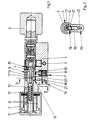
- FIG. 1 shows a double-profile locking cylinder Locking device with a housing 1 and two opposing handles 2, 3.
- the handles 2, 3 are each rotationally fixed to ends of one in the housing 1 stored core 4 or one connected to the core 4 Shaft 13 attached.
- the core 4 has a lock bit 5 for optional locking or unlock the locking device.
- One of Handles 2 is pot-shaped for receiving control electronics 6 designed.
- the control electronics 6 detects an access authorization for the locking device. In the event of An access authorization controls the control electronics 6 a positive connection of the housing 1 with the core 4 generating Locking mechanism 7 on.
- the locking mechanism 7 has one of an electromagnet 8 in a recess 9 movable locking bolt 10 on. In the drawn The recess 9 is on the opposite position Side of the latch 10.
- the access authorization can be determined in a variety of ways become.
- the control electronics 6 a code in front of the pot-shaped handle 2 or in one not shown reader held transponder receive and evaluate.
- the code becomes a Memory content compared and depending on that Comparison of access authorization determined or denied.
- the control electronics 6 can also with a also not shown, in addition to the Locking device arranged keyboard a combination of numbers query or unlock the locking device allow only during a time window.
- the housing 1 has a flange 12 for holding the Control electronics 6. In the center of the flange 12 is the passed through the core 4 connected shaft 13.
- the Shaft 13 is designed as a hollow shaft and with the bottom area the pot-shaped handle 2 welded.
- the wave 13 is in the normal position shown Locking device rotatably connected to a sleeve 14.
- the sleeve 14 is rotatably connected to the via a coupling 15 Closure bit 5 connected and has the recess 9 for the Locking mechanism 7. This allows the control electronics 6 overlapping handle 2 only when unlocked Turn locking mechanism 7.
- the sleeve 14 and the shaft 13 have an aligned recess 16 on.
- a holding part 17 is located in the recess 16 to create a positive connection between the shaft 13 and the sleeve 14 arranged.
- Unlocked in the drawn Position of the locking mechanism is the holding part 17 on a pin 18.
- the pin 18 is from a bolt 19 held with an eccentric 20.
- the bar 19 is with a cylindrical portion 21 in the Housing 1 stored. By rotating the bolt 19 can the pin 18 move downwards, so that Holding part 17 can fall out of the recess 16.
- the pot-shaped handle 2 can are pulled out of the housing 1 together with the shaft 13, to change the battery 11, for example.
- the clutch 15 By rotating the core 4 by means of the second handle 3, the clutch 15 can be separated and thus the non-rotatable Connection between the lock bit 5 and the sleeve 14 cancel. It can be independent from this side unlocked the locking device by an access authorization become.
- the control electronics can 6 opposite end of the core 4 instead the second handle 3 also a locking channel for one Keys and mechanical tumblers or one have another electronic locking mechanism.
- FIG 2 shows a sectional view through the Locking device from Figure 1. It can be seen here that the recess 16 for the holding part 17 radially is tapered on the inside.
- the holding part 17 is designed as a ball.
- the parting plane between the shaft 13 and the sleeve 14 runs in the upper half of the Holding part 17. This causes the Sleeve 14 opposite the shaft 13, the holding part 17 down pressed against the pin 18.
- the bolt 19 must as in Figure 1 shown can be rotated by 180 °. For this he has Bolt 19 is provided for attaching a screwdriver Slot 22.
Landscapes
- Physics & Mathematics (AREA)
- Electromagnetism (AREA)
- Engineering & Computer Science (AREA)
- Manufacturing & Machinery (AREA)
- General Physics & Mathematics (AREA)
- Lock And Its Accessories (AREA)
- Manipulator (AREA)
- Glass Compositions (AREA)
- Seal Device For Vehicle (AREA)
Applications Claiming Priority (2)
| Application Number | Priority Date | Filing Date | Title |
|---|---|---|---|
| DE19940246A DE19940246A1 (de) | 1999-08-25 | 1999-08-25 | Schließeinrichtung |
| DE19940246 | 1999-08-25 |
Publications (2)
| Publication Number | Publication Date |
|---|---|
| EP1079051A1 true EP1079051A1 (fr) | 2001-02-28 |
| EP1079051B1 EP1079051B1 (fr) | 2005-03-16 |
Family
ID=7919506
Family Applications (1)
| Application Number | Title | Priority Date | Filing Date |
|---|---|---|---|
| EP00112750A Expired - Lifetime EP1079051B1 (fr) | 1999-08-25 | 2000-06-16 | Dispositif de verrouillage |
Country Status (5)
| Country | Link |
|---|---|
| EP (1) | EP1079051B1 (fr) |
| AT (1) | ATE291142T1 (fr) |
| DE (2) | DE19940246A1 (fr) |
| ES (1) | ES2238221T3 (fr) |
| PT (1) | PT1079051E (fr) |
Cited By (18)
| Publication number | Priority date | Publication date | Assignee | Title |
|---|---|---|---|---|
| EP1188887A1 (fr) * | 2000-09-13 | 2002-03-20 | Kaba Gege GmbH | Serrure cylindrique double |
| EP1659238A1 (fr) * | 2004-10-12 | 2006-05-24 | Sitech-Sicherheitstechnik GmbH | Cylindre de fermeture |
| AT503439B1 (de) * | 2006-03-29 | 2007-10-15 | Evva Werke | Einrichtung zum elektrischen verbinden von elektrischen oder elektronischen bauteilen |
| EP1903168A2 (fr) * | 2006-09-22 | 2008-03-26 | Assa Abloy Identification Technology Group AB | Noyau de serrure électromécanique interchangeable |
| US7591160B2 (en) | 2004-03-11 | 2009-09-22 | Keso Ag | Electromechanical lock cylinder |
| EP2231967A1 (fr) * | 2007-12-18 | 2010-09-29 | Assa Oem AB | Dispositif de poignée |
| US7874190B2 (en) | 2003-06-23 | 2011-01-25 | Assa Abloy Ab | Electromechanical lock cylinder |
| US8028553B2 (en) | 2005-06-24 | 2011-10-04 | Assa Abloy Ab | Modular electromechanical lock cylinder |
| EP2172607A3 (fr) * | 2008-10-06 | 2012-08-29 | Burg-Wächter Kg | Cylindre de fermeture pour une serrure |
| EP2708682A3 (fr) * | 2012-09-12 | 2017-09-06 | Aug. Winkhaus GmbH & Co. KG | Cylindre de fermeture pour une clé électronique |
| EP2708681A3 (fr) * | 2012-09-12 | 2017-10-18 | Aug. Winkhaus GmbH & Co. KG | Cylindre de fermeture pour une clé électronique |
| EP3396641A1 (fr) * | 2017-04-25 | 2018-10-31 | Aug. Winkhaus GmbH & Co. KG | Installation de fermeture |
| USD926018S1 (en) | 2019-04-05 | 2021-07-27 | Dormakaba Usa Inc. | Knob |
| US11339589B2 (en) | 2018-04-13 | 2022-05-24 | Dormakaba Usa Inc. | Electro-mechanical lock core |
| US11466473B2 (en) | 2018-04-13 | 2022-10-11 | Dormakaba Usa Inc | Electro-mechanical lock core |
| EP4261369A1 (fr) | 2022-04-15 | 2023-10-18 | Digilock Asia Ltd. | Serrure cylindrique à commande électronique |
| US11913254B2 (en) | 2017-09-08 | 2024-02-27 | dormakaba USA, Inc. | Electro-mechanical lock core |
| US11933076B2 (en) | 2016-10-19 | 2024-03-19 | Dormakaba Usa Inc. | Electro-mechanical lock core |
Families Citing this family (2)
| Publication number | Priority date | Publication date | Assignee | Title |
|---|---|---|---|---|
| DE102007000491A1 (de) | 2007-11-09 | 2009-05-14 | Aug. Winkhaus Gmbh & Co. Kg | Schließzylinder |
| DE102014110970B3 (de) * | 2014-08-01 | 2015-10-15 | ASTRA Gesellschaft für Asset Management mbH & Co. KG | Schließzylinderanordnung |
Citations (4)
| Publication number | Priority date | Publication date | Assignee | Title |
|---|---|---|---|---|
| US4901545A (en) * | 1987-12-28 | 1990-02-20 | Rising Star Technologies (A Partnership) | Self-contained electromechanical locking device |
| EP0588209A1 (fr) * | 1992-09-15 | 1994-03-23 | Costruzioni Italiane Serrature Affini C.I.S.A. S.p.A. | Serrure avec activation électrique |
| DE29703559U1 (de) * | 1996-03-27 | 1997-04-30 | Lerchner Leonhard | Türschloß |
| DE19851308A1 (de) * | 1997-11-07 | 1999-05-12 | Terra Dom Hausbau Gmbh | Schließzylinder |
Family Cites Families (5)
| Publication number | Priority date | Publication date | Assignee | Title |
|---|---|---|---|---|
| DE4126160A1 (de) * | 1991-08-07 | 1993-02-11 | Winkhaus Fa August | Schliesszylinder, insbesondere fuer einsteckschloesser |
| GB9417748D0 (en) * | 1994-09-03 | 1994-10-19 | Yale Security Prod Ltd | Electrically operable cylinder lock |
| DE19517728C2 (de) * | 1995-05-15 | 1998-12-03 | Keso Gmbh | Schließvorrichtung |
| DE19524567C1 (de) * | 1995-07-06 | 1996-10-17 | Ikon Praezisionstechnik | Doppelzylinderschloß |
| DE19755218A1 (de) * | 1997-12-12 | 1999-06-17 | Bosch Gmbh Robert | Elektronische Schließvorrichtung |
-
1999
- 1999-08-25 DE DE19940246A patent/DE19940246A1/de not_active Withdrawn
-
2000
- 2000-06-16 DE DE50009767T patent/DE50009767D1/de not_active Expired - Fee Related
- 2000-06-16 AT AT00112750T patent/ATE291142T1/de not_active IP Right Cessation
- 2000-06-16 ES ES00112750T patent/ES2238221T3/es not_active Expired - Lifetime
- 2000-06-16 EP EP00112750A patent/EP1079051B1/fr not_active Expired - Lifetime
- 2000-06-16 PT PT00112750T patent/PT1079051E/pt unknown
Patent Citations (4)
| Publication number | Priority date | Publication date | Assignee | Title |
|---|---|---|---|---|
| US4901545A (en) * | 1987-12-28 | 1990-02-20 | Rising Star Technologies (A Partnership) | Self-contained electromechanical locking device |
| EP0588209A1 (fr) * | 1992-09-15 | 1994-03-23 | Costruzioni Italiane Serrature Affini C.I.S.A. S.p.A. | Serrure avec activation électrique |
| DE29703559U1 (de) * | 1996-03-27 | 1997-04-30 | Lerchner Leonhard | Türschloß |
| DE19851308A1 (de) * | 1997-11-07 | 1999-05-12 | Terra Dom Hausbau Gmbh | Schließzylinder |
Cited By (25)
| Publication number | Priority date | Publication date | Assignee | Title |
|---|---|---|---|---|
| EP1188887A1 (fr) * | 2000-09-13 | 2002-03-20 | Kaba Gege GmbH | Serrure cylindrique double |
| US7874190B2 (en) | 2003-06-23 | 2011-01-25 | Assa Abloy Ab | Electromechanical lock cylinder |
| US7591160B2 (en) | 2004-03-11 | 2009-09-22 | Keso Ag | Electromechanical lock cylinder |
| AU2005221741B2 (en) * | 2004-03-11 | 2009-11-12 | Keso Ag | Electromechanical lock cylinder |
| EP1659238A1 (fr) * | 2004-10-12 | 2006-05-24 | Sitech-Sicherheitstechnik GmbH | Cylindre de fermeture |
| US8028553B2 (en) | 2005-06-24 | 2011-10-04 | Assa Abloy Ab | Modular electromechanical lock cylinder |
| AT503439B1 (de) * | 2006-03-29 | 2007-10-15 | Evva Werke | Einrichtung zum elektrischen verbinden von elektrischen oder elektronischen bauteilen |
| EP1903168A2 (fr) * | 2006-09-22 | 2008-03-26 | Assa Abloy Identification Technology Group AB | Noyau de serrure électromécanique interchangeable |
| EP1903168A3 (fr) * | 2006-09-22 | 2008-10-15 | Assa Abloy AB | Noyau de serrure électromécanique interchangeable |
| US7845202B2 (en) | 2006-09-22 | 2010-12-07 | Assa Abloy Ab | Interchangeable electromechanical lock core |
| EP2231967A4 (fr) * | 2007-12-18 | 2014-11-05 | Assa Oem Ab | Dispositif de poignée |
| EP2231967A1 (fr) * | 2007-12-18 | 2010-09-29 | Assa Oem AB | Dispositif de poignée |
| EP2172607A3 (fr) * | 2008-10-06 | 2012-08-29 | Burg-Wächter Kg | Cylindre de fermeture pour une serrure |
| EP2708682A3 (fr) * | 2012-09-12 | 2017-09-06 | Aug. Winkhaus GmbH & Co. KG | Cylindre de fermeture pour une clé électronique |
| EP2708681A3 (fr) * | 2012-09-12 | 2017-10-18 | Aug. Winkhaus GmbH & Co. KG | Cylindre de fermeture pour une clé électronique |
| US11933076B2 (en) | 2016-10-19 | 2024-03-19 | Dormakaba Usa Inc. | Electro-mechanical lock core |
| EP3396641A1 (fr) * | 2017-04-25 | 2018-10-31 | Aug. Winkhaus GmbH & Co. KG | Installation de fermeture |
| US11913254B2 (en) | 2017-09-08 | 2024-02-27 | dormakaba USA, Inc. | Electro-mechanical lock core |
| US11466473B2 (en) | 2018-04-13 | 2022-10-11 | Dormakaba Usa Inc | Electro-mechanical lock core |
| US11339589B2 (en) | 2018-04-13 | 2022-05-24 | Dormakaba Usa Inc. | Electro-mechanical lock core |
| US11447980B2 (en) | 2018-04-13 | 2022-09-20 | Dormakaba Usa Inc. | Puller tool |
| USD937655S1 (en) | 2019-04-05 | 2021-12-07 | Dormakaba Usa Inc. | Knob |
| USD965407S1 (en) | 2019-04-05 | 2022-10-04 | Dormakaba Usa Inc | Knob |
| USD926018S1 (en) | 2019-04-05 | 2021-07-27 | Dormakaba Usa Inc. | Knob |
| EP4261369A1 (fr) | 2022-04-15 | 2023-10-18 | Digilock Asia Ltd. | Serrure cylindrique à commande électronique |
Also Published As
| Publication number | Publication date |
|---|---|
| DE19940246A1 (de) | 2001-03-08 |
| PT1079051E (pt) | 2005-07-29 |
| ES2238221T3 (es) | 2005-09-01 |
| EP1079051B1 (fr) | 2005-03-16 |
| ATE291142T1 (de) | 2005-04-15 |
| DE50009767D1 (de) | 2005-04-21 |
Similar Documents
| Publication | Publication Date | Title |
|---|---|---|
| EP1079051A1 (fr) | Dispositif de verrouillage | |
| EP0861959B1 (fr) | Serrure de sécurité avec contrôle d'accès | |
| EP0526904A1 (fr) | Serrure à cylindre, notamment pour serrure encastrée | |
| EP0146960A2 (fr) | Dispositif de commande débrayable d'un mécanisme de serrure à condamnation | |
| DE19930054C5 (de) | Elektromechanisches Schließsystem | |
| EP0978611B1 (fr) | Système de serrure | |
| EP0819810B1 (fr) | Ferrure pour une serrure | |
| EP1079050B1 (fr) | Dispositif de fermeture | |
| DE69511357T3 (de) | Elektrisch betätigtes Autotürschloss | |
| EP1135284B1 (fr) | Systeme de fermeture, notamment pour automobiles | |
| DE2905941C2 (de) | Mittels Permanentmagnet-Schlüssel betätigbarer Schließzylinder mit Permanentmagnet-Drehzuhaltungen | |
| EP3372760A1 (fr) | Unité électronique pour un dispositif de verrouillage et système de fermeture | |
| DE19653860C1 (de) | Schließsystem für Kraftfahrzeuge | |
| DE2930802A1 (de) | Unverletzbares lenkschloss | |
| DE19524567C1 (de) | Doppelzylinderschloß | |
| DE10225649B4 (de) | Ferngesteuert freigebbarer Schließzylinder | |
| EP1505229B1 (fr) | Cylindre de fermeture | |
| EP0173987A1 (fr) | Serrure complémentaire pour portes avec système de fermeture de sécurité | |
| DE10064403C2 (de) | Mechanisch und elektronisch codierte Ver- und Entriegelungsvorrichtung | |
| DE10017482B4 (de) | Lenkverriegelungsvorrichtung für eine Fahrzeuglenkanordnung | |
| DE19829958B4 (de) | Elektronisch-mechanisches Schließsystem | |
| EP1079052B1 (fr) | Serrure cylindrique | |
| DE3941068A1 (de) | Doppelschliesszylinder | |
| CH667126A5 (en) | Combined mechanical and electrical security door lock - includes mechanical and electronic number combination locks coupled to common locking mechanism | |
| DE10305419B3 (de) | Schließzylinder mit innenseitiger Knauf- und außenseitiger Schlüsselbetätigung |
Legal Events
| Date | Code | Title | Description |
|---|---|---|---|
| EUG | Se: european patent has lapsed | ||
| PUAI | Public reference made under article 153(3) epc to a published international application that has entered the european phase |
Free format text: ORIGINAL CODE: 0009012 |
|
| AK | Designated contracting states |
Kind code of ref document: A1 Designated state(s): AT BE CH CY DE DK ES FI FR GB GR IE IT LI LU MC NL PT SE |
|
| AX | Request for extension of the european patent |
Free format text: AL;LT;LV;MK;RO;SI |
|
| 17P | Request for examination filed |
Effective date: 20010711 |
|
| AKX | Designation fees paid |
Free format text: AT BE CH CY DE DK ES FI FR GB GR IE IT LI LU MC NL PT SE |
|
| 17Q | First examination report despatched |
Effective date: 20040701 |
|
| GRAP | Despatch of communication of intention to grant a patent |
Free format text: ORIGINAL CODE: EPIDOSNIGR1 |
|
| GRAS | Grant fee paid |
Free format text: ORIGINAL CODE: EPIDOSNIGR3 |
|
| GRAA | (expected) grant |
Free format text: ORIGINAL CODE: 0009210 |
|
| AK | Designated contracting states |
Kind code of ref document: B1 Designated state(s): AT BE CH CY DE DK ES FI FR GB GR IE IT LI LU MC NL PT SE |
|
| PG25 | Lapsed in a contracting state [announced via postgrant information from national office to epo] |
Ref country code: IE Free format text: LAPSE BECAUSE OF FAILURE TO SUBMIT A TRANSLATION OF THE DESCRIPTION OR TO PAY THE FEE WITHIN THE PRESCRIBED TIME-LIMIT Effective date: 20050316 |
|
| REG | Reference to a national code |
Ref country code: GB Ref legal event code: FG4D Free format text: NOT ENGLISH |
|
| REG | Reference to a national code |
Ref country code: CH Ref legal event code: EP |
|
| GBT | Gb: translation of ep patent filed (gb section 77(6)(a)/1977) |
Effective date: 20050316 |
|
| REG | Reference to a national code |
Ref country code: IE Ref legal event code: FG4D Free format text: GERMAN |
|
| REF | Corresponds to: |
Ref document number: 50009767 Country of ref document: DE Date of ref document: 20050421 Kind code of ref document: P |
|
| PG25 | Lapsed in a contracting state [announced via postgrant information from national office to epo] |
Ref country code: CY Free format text: LAPSE BECAUSE OF FAILURE TO SUBMIT A TRANSLATION OF THE DESCRIPTION OR TO PAY THE FEE WITHIN THE PRESCRIBED TIME-LIMIT Effective date: 20050616 Ref country code: LU Free format text: LAPSE BECAUSE OF NON-PAYMENT OF DUE FEES Effective date: 20050616 Ref country code: GR Free format text: LAPSE BECAUSE OF FAILURE TO SUBMIT A TRANSLATION OF THE DESCRIPTION OR TO PAY THE FEE WITHIN THE PRESCRIBED TIME-LIMIT Effective date: 20050616 Ref country code: DK Free format text: LAPSE BECAUSE OF FAILURE TO SUBMIT A TRANSLATION OF THE DESCRIPTION OR TO PAY THE FEE WITHIN THE PRESCRIBED TIME-LIMIT Effective date: 20050616 |
|
| PG25 | Lapsed in a contracting state [announced via postgrant information from national office to epo] |
Ref country code: MC Free format text: LAPSE BECAUSE OF NON-PAYMENT OF DUE FEES Effective date: 20050630 Ref country code: CH Free format text: LAPSE BECAUSE OF NON-PAYMENT OF DUE FEES Effective date: 20050630 Ref country code: LI Free format text: LAPSE BECAUSE OF NON-PAYMENT OF DUE FEES Effective date: 20050630 |
|
| REG | Reference to a national code |
Ref country code: SE Ref legal event code: TRGR |
|
| REG | Reference to a national code |
Ref country code: PT Ref legal event code: SC4A Effective date: 20050523 |
|
| REG | Reference to a national code |
Ref country code: ES Ref legal event code: FG2A Ref document number: 2238221 Country of ref document: ES Kind code of ref document: T3 |
|
| REG | Reference to a national code |
Ref country code: IE Ref legal event code: FD4D |
|
| ET | Fr: translation filed | ||
| PLBE | No opposition filed within time limit |
Free format text: ORIGINAL CODE: 0009261 |
|
| STAA | Information on the status of an ep patent application or granted ep patent |
Free format text: STATUS: NO OPPOSITION FILED WITHIN TIME LIMIT |
|
| REG | Reference to a national code |
Ref country code: CH Ref legal event code: PL |
|
| 26N | No opposition filed |
Effective date: 20051219 |
|
| PGFP | Annual fee paid to national office [announced via postgrant information from national office to epo] |
Ref country code: PT Payment date: 20060523 Year of fee payment: 7 |
|
| PGFP | Annual fee paid to national office [announced via postgrant information from national office to epo] |
Ref country code: FI Payment date: 20060609 Year of fee payment: 7 Ref country code: SE Payment date: 20060609 Year of fee payment: 7 |
|
| PGFP | Annual fee paid to national office [announced via postgrant information from national office to epo] |
Ref country code: GB Payment date: 20060706 Year of fee payment: 7 |
|
| REG | Reference to a national code |
Ref country code: PT Ref legal event code: MM4A Free format text: LAPSE DUE TO NON-PAYMENT OF FEES Effective date: 20071217 |
|
| PG25 | Lapsed in a contracting state [announced via postgrant information from national office to epo] |
Ref country code: FI Free format text: LAPSE BECAUSE OF NON-PAYMENT OF DUE FEES Effective date: 20070616 Ref country code: PT Free format text: LAPSE BECAUSE OF NON-PAYMENT OF DUE FEES Effective date: 20071217 |
|
| EUG | Se: european patent has lapsed | ||
| GBPC | Gb: european patent ceased through non-payment of renewal fee |
Effective date: 20070616 |
|
| PG25 | Lapsed in a contracting state [announced via postgrant information from national office to epo] |
Ref country code: GB Free format text: LAPSE BECAUSE OF NON-PAYMENT OF DUE FEES Effective date: 20070616 |
|
| PG25 | Lapsed in a contracting state [announced via postgrant information from national office to epo] |
Ref country code: SE Free format text: LAPSE BECAUSE OF NON-PAYMENT OF DUE FEES Effective date: 20070617 |
|
| PGFP | Annual fee paid to national office [announced via postgrant information from national office to epo] |
Ref country code: ES Payment date: 20080617 Year of fee payment: 9 |
|
| PGFP | Annual fee paid to national office [announced via postgrant information from national office to epo] |
Ref country code: AT Payment date: 20080624 Year of fee payment: 9 |
|
| PGFP | Annual fee paid to national office [announced via postgrant information from national office to epo] |
Ref country code: IT Payment date: 20080620 Year of fee payment: 9 |
|
| PGFP | Annual fee paid to national office [announced via postgrant information from national office to epo] |
Ref country code: DE Payment date: 20080624 Year of fee payment: 9 Ref country code: NL Payment date: 20080630 Year of fee payment: 9 |
|
| PGFP | Annual fee paid to national office [announced via postgrant information from national office to epo] |
Ref country code: FR Payment date: 20080626 Year of fee payment: 9 |
|
| PGFP | Annual fee paid to national office [announced via postgrant information from national office to epo] |
Ref country code: BE Payment date: 20080701 Year of fee payment: 9 |
|
| BERE | Be: lapsed |
Owner name: AUG. *WINKHAUS G.M.B.H. & CO. K.G. Effective date: 20090630 |
|
| NLV4 | Nl: lapsed or anulled due to non-payment of the annual fee |
Effective date: 20100101 |
|
| REG | Reference to a national code |
Ref country code: FR Ref legal event code: ST Effective date: 20100226 |
|
| PG25 | Lapsed in a contracting state [announced via postgrant information from national office to epo] |
Ref country code: FR Free format text: LAPSE BECAUSE OF NON-PAYMENT OF DUE FEES Effective date: 20090630 |
|
| PG25 | Lapsed in a contracting state [announced via postgrant information from national office to epo] |
Ref country code: AT Free format text: LAPSE BECAUSE OF NON-PAYMENT OF DUE FEES Effective date: 20090616 Ref country code: BE Free format text: LAPSE BECAUSE OF NON-PAYMENT OF DUE FEES Effective date: 20090630 Ref country code: DE Free format text: LAPSE BECAUSE OF NON-PAYMENT OF DUE FEES Effective date: 20100101 |
|
| PG25 | Lapsed in a contracting state [announced via postgrant information from national office to epo] |
Ref country code: NL Free format text: LAPSE BECAUSE OF NON-PAYMENT OF DUE FEES Effective date: 20100101 |
|
| REG | Reference to a national code |
Ref country code: ES Ref legal event code: FD2A Effective date: 20090617 |
|
| PG25 | Lapsed in a contracting state [announced via postgrant information from national office to epo] |
Ref country code: ES Free format text: LAPSE BECAUSE OF NON-PAYMENT OF DUE FEES Effective date: 20090617 |
|
| PG25 | Lapsed in a contracting state [announced via postgrant information from national office to epo] |
Ref country code: IT Free format text: LAPSE BECAUSE OF NON-PAYMENT OF DUE FEES Effective date: 20090616 |