EP1072415A2 - Liquid discharging method, liquid discharge head and liquid discharging apparatus - Google Patents
Liquid discharging method, liquid discharge head and liquid discharging apparatus Download PDFInfo
- Publication number
- EP1072415A2 EP1072415A2 EP00116019A EP00116019A EP1072415A2 EP 1072415 A2 EP1072415 A2 EP 1072415A2 EP 00116019 A EP00116019 A EP 00116019A EP 00116019 A EP00116019 A EP 00116019A EP 1072415 A2 EP1072415 A2 EP 1072415A2
- Authority
- EP
- European Patent Office
- Prior art keywords
- liquid
- bubble
- movable member
- liquid flow
- discharge port
- Prior art date
- Legal status (The legal status is an assumption and is not a legal conclusion. Google has not performed a legal analysis and makes no representation as to the accuracy of the status listed.)
- Withdrawn
Links
Images


Classifications
-
- B—PERFORMING OPERATIONS; TRANSPORTING
- B41—PRINTING; LINING MACHINES; TYPEWRITERS; STAMPS
- B41J—TYPEWRITERS; SELECTIVE PRINTING MECHANISMS, i.e. MECHANISMS PRINTING OTHERWISE THAN FROM A FORME; CORRECTION OF TYPOGRAPHICAL ERRORS
- B41J2/00—Typewriters or selective printing mechanisms characterised by the printing or marking process for which they are designed
- B41J2/005—Typewriters or selective printing mechanisms characterised by the printing or marking process for which they are designed characterised by bringing liquid or particles selectively into contact with a printing material
- B41J2/01—Ink jet
- B41J2/135—Nozzles
- B41J2/14—Structure thereof only for on-demand ink jet heads
- B41J2/14016—Structure of bubble jet print heads
- B41J2/14032—Structure of the pressure chamber
- B41J2/14048—Movable member in the chamber
-
- B—PERFORMING OPERATIONS; TRANSPORTING
- B41—PRINTING; LINING MACHINES; TYPEWRITERS; STAMPS
- B41J—TYPEWRITERS; SELECTIVE PRINTING MECHANISMS, i.e. MECHANISMS PRINTING OTHERWISE THAN FROM A FORME; CORRECTION OF TYPOGRAPHICAL ERRORS
- B41J2/00—Typewriters or selective printing mechanisms characterised by the printing or marking process for which they are designed
- B41J2/005—Typewriters or selective printing mechanisms characterised by the printing or marking process for which they are designed characterised by bringing liquid or particles selectively into contact with a printing material
- B41J2/01—Ink jet
- B41J2/015—Ink jet characterised by the jet generation process
- B41J2/04—Ink jet characterised by the jet generation process generating single droplets or particles on demand
- B41J2/045—Ink jet characterised by the jet generation process generating single droplets or particles on demand by pressure, e.g. electromechanical transducers
- B41J2/055—Devices for absorbing or preventing back-pressure
Definitions
- the present invention relates to a liquid discharging apparatus for discharging liquid by generating a bubble by the application of heat energy on the liquid, and more particularly to a liquid discharging apparatus having a movable member which displaces by taking advantage of generation of the bubble.
- recording in the present invention is not only to impart a significant image such as characters and patterns onto a recording medium, but also to impart a meaningless image including any other than patterns or the like.
- an ink jet recording method a so-called bubble jet recording method, in which, in a recording apparatus such as printers, the bubble is generated by imparting energy such as heat to liquid ink in a flow path, and the ink is discharged through discharging ports by means of an operating force based on a sudden volume change caused by the occurrence of the bubble to cause the ink to adhere onto a recording medium for forming an image.
- a recording apparatus using this bubble jet recording method is generally provided, as disclosed in specification of U.S. Patent No. 4,723,129 or the like, with discharging ports through which the ink is discharged, flow paths communicated to these discharging ports, and electrothermal transducers as energy generating means for discharging the ink provided within the flow paths.
- Such a recording method has many excellent advantages that it is possible to easily obtain a recorded image with high resolution and further, a color image with a small-sized apparatus because a high-quality image can be recorded at high speed and in low noise and a head in which this recording method is performed can be at high density provided with discharging ports for discharging the ink. For this reason, this bubble jet recording method has been utilized for many office equipment such as printers, copying machines and facsimile apparatuses in recent years, and further for industrial systems such as textile printing apparatuses.
- the heater is located at the bottom of a concave portion and cannot be linearly communicated to the discharging ports, and therefore, the shape of liquid droplets cannot be stabilized. Further, since the growth of the bubble is allowed around the vertex of the triangle, the bubble grow from one side of the triangular plate-shaped member to the entire opposite side, with the result that normal growth of the bubble in the liquid is completed as if there existed no plate-shaped members. Therefore, the existence of the plate-shaped member would have nothing to do with grown the bubble.
- EP Patent Application Laid-Open No. 436047A1 has proposed an invention in which a first valve for intercepting a relation between a discharge port-neighboring area and the bubble generating unit and a second valve for completely intercepting a relation between the bubble generating unit and an ink supply unit are caused to be alternately opened and closed (Figs. 4 to 9 of EP436047A1).
- a number of inventions using a movable member (a plate-shaped member having a free end closer to the discharge port side than a support, or the like) capable of effectively contributing to discharging of liquid droplets quite unlike the above described prior art.
- a Japanese Patent Application Laid-Open No. 9-48127 discloses an invention in which the upper limit of displacement of the movable member is regulated in order to prevent behavior of the above described movable member from being slightly confused.
- 9-323420 discloses an invention in which an upstream common liquid chamber is shifted on the free end side of the movable member, that is, on the downstream side by the utilization of the advantage of the movable member to enhance the refilling ability.
- These inventions do not focus attention on individual elements concerning formation of the liquid droplet by the entire bubble and correlation of those elements because, as a precondition for the invention, there has been supposed a form in which the growth of the bubble is released on the discharge port side at a stroke from a state in which it is temporarily wrapped by the movable member.
- the displacement of the movable member cannot catch up with the growth of the bubble, but the grown a bubble is going to go on to the upper surface of the movable member.
- the liquid supply-side flow path resistance is very low and the liquid is prone to move in that direction, it was observed that the bubble go round to the rear of nozzle flow path along with the movement of the liquid to the rear of nozzle flow path caused by displacement of the movable member.
- the present inventors have newly found, in the nozzle flow path for a liquid discharging head using a movable member having a free end, a liquid flow to the rear of flow path in a process of valve displacement, and configuration of a flow path to prevent the bubble from going round to the rear of flow path due to the liquid flow, whereby the discharging efficiency forward of the nozzles is improved, and return to meniscus and early-stabilization of the filling liquid during refilling are performed.
- the present invention obtained in such study process as described above is characterized in that, there is provided a liquid discharge method through a liquid discharge head provided with a liquid flow path having a bubble generating area, in which a bubble is generated from liquid; a heater for generating heat energy to generate and grow the bubble; a discharge port which communicates to the liquid flow path and is a portion for discharging the liquid; a movable member provided in the bubble generating area, having a free end which shifts along with growth of the bubble; and a liquid flow regulating portion for regulating liquid flow in a direction opposite to the discharge port in a displacement process of the movable member and the growth of the bubble, having a step of forming space substantially closed in the liquid flow path having the bubble generating area except for the discharge port by bringing the free end of the movable member in the displacement process, close to the liquid flow regulating portion without substantially contacting each other.
- the above described method is characterized in that, in a process in which the free end of the movable member shifts, the liquid flow in a direction opposite to the discharge port is sheared when the free end is passing through the vicinity of the liquid flow regulating portion.
- the method is characterized by having a process in which the bubble shrinks in a state where the closed space is formed.
- the method is characterized in that, in the process in which the bubble shrinks, the greater part of the liquid which moves along with the shrinkage of the bubble is directed toward the upstream side from the discharge port and meniscus is suddenly drawn into the discharge port.
- the method is characterized in that the movable member is spaced apart from the liquid flow regulating portion along with the shrinkage of the bubble, whereby a liquid flow toward the downstream side facing the discharge port is caused in the bubble generating area to thereby suddenly brake the meniscus to be drawn in.
- a liquid discharge head having: a liquid flow path having a bubble generating area, in which a bubble is generated from liquid; a heater for generating heat energy to generate and grow the bubble; a discharge port which communicates to the liquid flow path and is a portion for discharging the liquid; a movable member provided in the bubble generating area, having a free end which shifts along with the growth of the bubble; and a liquid flow regulating portion for regulating liquid flow in a direction opposite to the discharge port in the displacement process of the movable member and the growth of the bubble, in which the free end of the movable member in the displacement process and the liquid flow regulating portion are brought close to each other without actually bringing them into contact with each other, whereby the liquid flow path having the bubble generating area becomes space substantially closed except for the discharge port, and wherein there are arranged the movable member and the liquid flow regulating portion such that a bubble at the maximum growth does not intercept the interior of the space with reference to the fluid flow.
- the above described head is characterized in that the liquid flow regulating portion is provided in the vicinity of the discharge port side of the displacement area of the free end of the movable member.
- the liquid discharge head is characterized in that there has been provided a displacement regulating unit for regulating displacement of the movable member after the formation of the closed space. This enables the refilling property to be enhanced by restraining the movement of the liquid to the upstream side after the formation of the closed space.
- the liquid discharge head is characterized in that there has been provided a side regulating unit, at least one portion of which substantially comes into contact with both side edges of the movable member in the displacement process, for regulating a bubble generated from the bubble generating area. This enables, even if a clearance between the side walls of the liquid flow path and the movable member is set loose, the liquid flow from the clearance to the upstream side and the growth of a bubble to be restrained.
- the liquid flow regulating portion is characterized in that it is located closer to the discharge port side than the free end of the movable member, and, when viewed from the discharge port, the free end of the movable member in the displacement process is covered and the liquid flow regulating portion is kept at such a distance as not to bring it into contact with the free end.
- the liquid discharge head is characterized in that, in the process in which the free end of the movable member shifts, the locus portion of the free end when the free end is passing through the vicinity of the liquid flow regulating portion is narrow space. This causes the liquid flow on the upstream side due to upward displacement of the movable member to become faster, and therefore, the displacement speed of the movable member is also made faster.
- the upstream-side portion of the liquid flow regulating portion is characterized by having a tapered configuration which tapers downwards from the flow path ceiling. This enables the flow path resistance during refilling from the upstream side to be reduced. Further, since the width of the liquid flow regulating portion in the flow path direction can be reduced, it is possible to secure a large flow path volume on the discharge port side with the liquid flow regulating portion as the border, which is useful to discharge large liquid droplets.
- the movable member is characterized by having a protruded portion which protrudes from the surf ace of the movable member on the heater side in the vicinity of the bubble generating area. This enables pressure waves when the bubble is generated not to affect the upstream side as far as possible.
- the liquid flow on the upstream side and the growth of the bubble which bring a minus effect to the refilling property, are intercepted smoothly and quickly without bringing the movable member in the displacement process into contact to thereby substantially make the liquid flow path having the bubble generating area into substantially closed space, and thus the discharging energy due to the growth of the bubble can be effectively directed toward the discharge port.
- upstream and downstream used in the description of the present invention are represented as expression concerning a direction of flow of the liquid from the supply source thereof toward the discharge port through the bubble generating area (or movable member), or the direction in this configuration.
- downstream side concerning the bubble itself means the downstream side concerning the above described direction of flow or the direction in the above described configuration with respect to the center of the bubble, or a bubble which is generated in an area on the downstream side of the center of area of the heater.
- a “substantially contact” between the movable member and the side regulating unit which is expressed in the present invention, does not always mean that the movable member and the side regulating unit are brought into tight contact with each other, but also includes that the movable member comes unlimitedly close to the side regulating unit.
- Figs. 1A1 to 1F1 and Figs. 1A2 to 1F2 are sectional views showing a liquid discharge head according to a first embodiment of the present invention, and showing characteristic phenomena within a liquid flow path divided into six processes.
- Figs. 1A1 to 1F1 are sectional views obtained by cutting in a direction along a flow path
- Figs. 1A2 to 1F2 are sectional views taken on lines 1A2-1A2, 1B2-1B2, 1C2-1C2, 1D2-1D2, 1E2-1E2 and 1F2-1F2 corresponding to Figs. 1A1 to 1F1, respectively.
- a liquid discharge head having the embodiment shown in Figs. 1A1 to 1F1
- an element substrate 1 and a ceiling plate 2 are fixed in a stacked state, and a flow path 3 is provided between both plates 1 and 2.
- the flow path 3 is enclosed with the element substrate 1, side walls 7 and the ceiling plate-(opposite plate) 2, having a long and narrow shape, and one recording head is provided with a multiplicity of flow paths 3.
- a common liquid chamber 6 having a large capacity on the upstream side of these multiplicity of flow paths 3 so as to communicate to all of them.
- the single common liquid chamber 6 is branched to the multiplicity of flow paths 3.
- a symbol M designates meniscus to be formed by the discharging liquid, and the meniscus M is well-balanced near the discharge port 4 with an internal pressure of the common liquid chamber 6, which is normally negative pressure, by means of a capillary force which is caused by the discharge port 4 and the inner walls of the flow path 3 communicating thereto.
- the liquid chamber height of the common liquid chamber 6 is much higher than the flow path height of the flow path 3.
- the element substrate 1 is mounted with heaters (bubble generating means) 10 such as electrothermal transducers and movable members 11.
- the movable member 11 is cantilever beam-shaped with one end supported, is fixed to the element substrate 1 on the upstream side (right side of Fig. 1A1) of ink flow, and is vertically movable with respect to the element substrate 1 on the downstream side (left side of Fig. 1A1) of a support 11a.
- the movable member 11 is located in parallel to the element substrate 1 while a slight gap is maintained between the element substrate 1 and the movable member 11 in an initial state shown in Fig. 1A1.
- the movable member 11 is arranged in such a manner that a free end 11b is located at a substantially central area of the heater 10 in order to restrain growth of nearly half of the bubble on the upstream side, and, in the upper part of the immediately preceding space of the free end 11b of this movable member 11, there is provided a liquid flow regulating portion 12 for regulating the liquid flow in a direction that forms the flow path 3, so as to intercept the liquid flow toward the upstream side (to the rear) of the liquid path 3 in the displacement process of the movable member 11 caused by the growth of the bubble, and the growth on the upstream side of the flow path 3 of the bubble which goes around the free end lib of the movable member 11 caused by the liquid flow.
- the liquid flow regulating portion 12 is located closer to the discharge port 4 side than the free end 11b of the movable member 11, and, when the common liquid chamber 6 side is viewed from the discharge port 4, the liquid flow regulating portion 12 covers the free end 11b of the movable member 11 under displacement and is kept at such a distance as not to bring it into contact with the free end 11b.
- the liquid flow regulating portion 12 is, in a process in which the free end 11b of the movable member 11 shifts, located so as to shear the liquid flow toward the upstream side of the flow path 3 when the free end 11b is passing through near the side surface of the liquid flow regulating member 12 on the upstream side.
- the liquid flow regulating portion is provided in the vicinity of the discharge port side in the displacement area of the free end of the movable member.
- the ceiling on the common liquid chamber 6 side is shaped to suddenly rise with the liquid flow regulating portion 12 as the border.
- it is difficult to direct pressure to be used for discharging toward the discharge port 4 side because the fluid resistance in the bubble generating area 9 on the downstream side becomes lower than that on the upstream side.
- the pressure used for discharging is positively directed toward the discharge port 4 side, and since the fluid resistance in the bubble generating area 9 on the upstream side is low at the time of ink supply, the ink is to be quickly supplied to the bubble generating area 9.
- growth components of the bubble toward the downstream side are not equal to growth components of the bubble toward the upstream side, but the growth components toward the upstream side become fewer, and the movement of the liquid toward the upstream side is restrained. Since the flow of liquid toward the upstream side is restrained, an amount of backward movement of meniscus after discharging is reduced, and an amount of protrusion of the meniscus from the orifice surface during refilling is also reduced by that amount. Therefore, the meniscus vibration will be restrained, resulting in stable discharging at all driving frequencies from low frequency to high frequency.
- a liquid flow between the portion of the bubble on the downstream side and the discharge port is in a "linearly-communicated state", in which straight flow path configuration is maintained. It is more preferable that a propagation direction of pressure waves which are generated when the bubble are produced, a flowing direction of the liquid caused thereby, and the discharging direction are linearly aligned. It is desirable to form an ideal state in which the discharging state such as a discharging direction and a discharging speed of a discharging droplet 66 is stabilized at a very high level.
- the discharge port 4 the heater 10 and the discharge port side (downstream side) of the heater, which particularly affects the discharge port side of the bubble, can be constructed to be directly connected in a straight line.
- This is a state in which, if there is no liquid within the flow path, the heater, and particularly the downstream side thereof could be observed as viewed from the outside of the discharge port (See Fig. 21).
- the movable member 11 in proximity to the bubble generating area 9, the movable member 11 is provided with a protruded portion 11c (hereinafter, referred to as "lower protruded portion” simply) which protrudes on the substrate 1 side.
- This lower protruded portion 11c is used to restrain growth of a bubble, which is generated in the bubble generating area 9, toward the rear (upstream side), and the provision of this lower protruded portion 11c reduces the backward growth of the bubble.
- this lower protruded portion 11c can contribute to improved discharging energy by restraining the backward growth of the bubble.
- the lower protruded portion 11c As a position whereat the lower protruded portion 11c is provided, it is preferably provided at a position at least apart from a stepped portion around the heater 10 because the lower protruded portion 11c may abut against the substrate 1 when the movable member 11 shifts on the substrate 1 side. Concretely, it is preferably apart from an effective foaming area by 5 ⁇ m or more. Since when it is located excessively far from the bubble generating area, the effect of restraining the backward growth of the bubble cannot be exhibited, it is preferably provided within a distance of substantially half the heater length from the effective foaming area of the heater 10. More specifically, in this embodiment, it is about 45 ⁇ m, preferably within 30 ⁇ m, and more preferably 20 ⁇ m or less.
- the height of the lower protruded portion 11c is nearly equal to or less than the distance between the movable member 11 and the element substrate 1, and in this embodiment, there is a slight clearance between the tip end of the lower protruded portion 11c and the element substrate 1.
- Fig. 1A1 shows a state before energy such as electrical energy is applied to the heater 10, or a state before the heater generates heat. It is important here that the width of the movable member is sufficiently smaller than the width of the flow path and a clearance between the movable member and the flow path walls is secured, and that there is provided a liquid flow regulating portion 12 which performs early interception of the liquid flow toward the upstream side (to the rear) of the liquid path 3 in the displacement process of the movable member 11 caused by the growth of the bubble, and which performs restraint of the growth, on the upstream side of the flow path 3, of the bubble which goes around the free end 11b of the movable member 11 caused by the liquid flow.
- Fig. 1B1 shows a state in which a portion of the liquid which fills the bubble generating area 9 is heated by the heater 10 and a bubble 40 caused by film boiling starts to bubble.
- Fig. 1C1 shows a state in which a portion of the liquid which fills the bubble generating area 9 is heated by the heater 10 and a bubble 40 caused by film boiling has grown at the substantially maximum.
- pressure waves based on the occurrence of the bubble 40 caused by film boiling further propagate, whereby, on the upstream side of the bubble generating area 9, the movable member 11 shifts until the free end 11b thereof is arranged in the vicinity of one surface (rear surface), on the upstream side, of the liquid flow regulating portion 12, and, on the downstream side, a discharge droplet 66 is being discharged through the discharge port 4.
- the movable member 11 shifts to the position shown in Fig. 1C1, the movement of the liquid in the upstream direction is greatly limited there.
- the liquid flow regulating portion 12, the flow path side walls 7, the movable member 11 and a support 11a bring the amount of liquid, which enters the upstream side area, to substantially naught. This prevents an inverted flow and pressure vibration of the liquid in a supply path system for inhibiting high-speed refilling to be described later.
- the movable member 11 can continue to shift while the state of the liquid flow A remains, and smoothly passes through near the surface (rear surface) of the liquid flow regulating portion 12 on the upstream side. Since the presence of the liquid flow regulating portion 12 provides the locus portion of the free end 11b of the movable member 11 with narrow space at the time of this passage, the flow velocity of the liquid flow A is made faster, the flowing resistance is made lower, and the upward displacement speed of the movable member 11 is also made faster.
- the liquid path 3 having the bubble generating area 9 completes substantial closed space except for the discharge port 4 by means of the movable member 11 and the liquid flow regulating portion 12. For this reason, the liquid moving force within this space is almost all directed toward the discharge port side to increase the discharging force, and the movement of liquid toward the supply side (upstream side), which provides a minus effect to the refilling property, is almost eliminated (See Fig. 2C).
- Fig. 1D1 shows a state in which negative pressure within the bubble overcomes the movement of liquid toward the downstream side within the liquid flow path after the above described film boiling to start shrinkage of the bubble 40.
- the flow path 3 having the bubble generating area 9 is substantially closed space except for the discharge port 4 because of the closely-positioned state between the movable member 11 shifted and the liquid flow regulating portion 12 as the entire liquid flow path. Therefore, shrinkage energy of the bubble 40 strongly works as a force for moving the liquid near the discharge port 4 in the upstream direction in balance as a whole. Therefore, the meniscus M is greatly drawn into the flow path 3 from the discharge port 4 at this point of time to quickly cut off a liquid column connected to the discharged liquid droplet 66 with a strong force. As a result, as shown in Fig. 1E1, the liquid droplet remained in the outside of the discharge port 4, that is, satellite (sub-droplet) 67 becomes fewer.
- Fig. 1E1 shows a state in which a bubble disappearing process has been substantially completed and the discharged liquid droplet 66 has been separated from the meniscus M.
- the liquid guided into the flow path passes through between the liquid flow regulating portion 12 and the movable member 11 shifted downward as it is, flows into the downstream side of the heater 10, and operates to accelerate bubble disappearance of the bubble 40 which has not yet been disappeared.
- the flow of this liquid further flows toward the discharge port after assists in bubble disappearing, assists in returning the meniscus and improves the refilling speed.
- Fig. 1F1 shows a state in which the state of Fig. 1E1 further advances and the satellite 67 is taken into the discharged droplet 66.
- This coalescence of the discharged droplet 66 and the satellite 67 is not a phenomenon which always takes place for each discharge even in other embodiments, but there are cases where it takes place and where it does not depending upon the conditions. If, however, the amount of satellite is at least reduced or eliminated, shot positions of main droplets and satellite dots will rarely deviate on the recording medium, thus making it possible to improve the printing quality and to reduce detrimental effects such as contamination of the printing medium or the interior of the recording apparatus with ink mist, or the like.
- Figs. 3A to 3C are sectional views showing a liquid discharge head according to a second embodiment of the present invention.
- Fig. 3A is a sectional views obtained by cutting in a direction along a flow path
- Fig. 3B is a sectional views taken on line 3B-3B of Fig. 3A
- Fig. 3C is a sectional views taken on line 3C-3C of Fig. 3A.
- components identical to those in Figs. 1A1 to 1F1 are designated by the identical reference numerals, and description of the identical components will be omitted.
- This embodiment is, in addition to a configuration of the first embodiment, constructed such that a side wall 7 of the flow path 3 upstream of the liquid flow regulating portion 12 is provided, as shown in Figs. 3A to 3C, with a side stopper 13, against which the upper surface of side edge of the movable member 11 abuts during upward displacement, and that a clearance between the movable member 11 and the flow path wall 7 is intercepted during displacement of the movable member 11.
- the height of the abutment surface between the side stopper 13 and the movable member 11 is preferably determined in such a manner that the movable member 11 shifted is located at a position whereat it abuts after it passes through in the vicinity of the surface (rear surface) of the liquid flow regulating portion 12 on the upstream side.
- the side stopper 13 is provided from the ceiling of the flow path 3, but the present invention is not limited thereto, but the side stopper 13 may be provided only for the side wall 7 of the flow path 3, and the shape of the side stopper 13 is not restricted so long as the upper surface of side edge of the movable member 11 during upward replacement abuts.
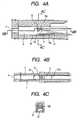
- Figs. 4A to 4C are sectional views showing a liquid discharge head according to a third embodiment of the present invention.
- Fig. 4A is a sectional views obtained by cutting in a direction along a flow path
- Fig. 4B is a sectional views taken on line 4B-4B of Fig. 4A
- Fig. 4C is a sectional views taken on line 4C-4C of Fig. 4A.
- components identical to those in Figs. 1A1 to 1F1 are designated by the identical reference numerals, and description of the identical components will be omitted.
- This embodiment is, in addition to the configuration of the first embodiment, constructed such that an upstream-side portion of the liquid flow regulating portion 12 is provided, as shown in Figs. 4A to 4C, with a displacement regulating unit 12a, against which the free end 11b of the movable member 11 during upward displacement abuts, and the displacement of the movable member 11 is regulated after the free end 11b of the movable member 11 passes in the vicinity of the surface of the liquid flow regulating portion 12 on the upstream side.
- the abutment surface between the displacement regulating unit 12a and the movable member 11 is, naturally, located higher than the tip end (lower end) of the liquid flow regulating portion 12 (near the flow path ceiling).
- Figs. 5A to 5C are sectional views showing a liquid discharge head according to a fourth embodiment of the present invention.
- Fig. 5A is a sectional views obtained by cutting in a direction along a flow path
- Fig. 5B is a sectional views taken on line 5B-5B of Fig. 5A
- Fig. 5C is a sectional views taken on line 5C-5C of Fig. 5A.
- components identical to those in Figs. 1A1 to 1F1 are designated by the identical reference numerals, and description of the identical components will be omitted.
- the embodiment shown in Figs. 5A to 5C is, in addition to the configuration of the first embodiment, constructed such that the upstream-side portion of the liquid flow regulating portion 12 is provided with a displacement regulating unit 12a for regulating the displacement of the movable member 11, the free end 11b of which has passed the vicinity of the surface (rear surface) of the liquid flow regulating portion 12 on the upstream side, and that the side wall 7 of the flow path 3 upstream of the displacement regulating unit 12a is provided with a side stopper 13, against which the upper surface of side edge of the movable member 11 abuts, so as to intercept a clearance between the movable member 11 and the flow path wall 7.
- Such configuration has effects obtained by combining the second embodiment with the third embodiment. More specifically, leakage of the liquid and the bubble from the clearance portion between the movable member 11 caused by the upward displacement thereof and the flow path wall is prevented, and, after the liquid flow toward the upstream side is intercepted by the liquid flow regulating portion 12 and the movable member 11, the displacement of the movable member is quickly regulated. Therefore, it is possible to cause the growth of the bubble to contribute to formation of discharged liquid droplets more efficiently, and to improve the refilling property.
- Figs. 6A to 6C are sectional views showing a liquid discharge head according to a fifth embodiment of the present invention.
- Fig. 6A is a sectional views obtained by cutting in a direction along a flow path
- Fig. 6B is a sectional views taken on line 6B-6B of Fig. 6A
- Fig. 6C is a sectional views taken on line 6Y-6Y of Fig. 6A.
- components identical to those in Figs. 1A1 to 1F1 are designated by the identical reference numerals, and description of the identical components will be omitted.
- a liquid flow regulating portion 121 is constructed by forming the upstream-side portion of the liquid flow regulating portion of the first embodiment into a tapered configuration which tapers downwards from the flow path ceiling as shown in Figs. 6A to 6C, and along the locus of the free end 11b of the movable member 11 during upward displacement.
- the width of the liquid flow regulating portion in the front-to-back direction can be made smaller than in the first embodiment, the volume of flow path on the discharge port side with the liquid flow regulating portion and the movable member as the border can be secured great, which is useful to discharge large liquid droplets (large dots). This is because the maximum discharge-able liquid droplet amount is proportionate to the flow path volume from the heater to the discharge port. Further, since the upstream-side portion of the liquid flow regulating portion 121 is formed into a tapered configuration, the flow path resistance from the upstream side during refilling can be reduced.
- Figs. 7A to 7C are sectional views showing a liquid discharge head according to a sixth embodiment of the present invention.
- Fig. 7A is a sectional views obtained by cutting in a direction along a flow path
- Fig. 7B is a sectional views taken on line 7B-7B of Fig. 7A
- Fig. 7C is a sectional views taken on line 7C-7C of Fig. 7A.
- components identical to those in Figs. 1A1 to 1F1 are designated by the identical reference numerals, and description of the identical components will be omitted.
- a liquid flow regulating portion 121 is constructed by forming the upstream-side portion of the liquid flow regulating portion of the first embodiment into a tapered configuration which tapers downwards from the flow path ceiling as shown in Figs. 7A to 7C, and along the locus of the free end 11b of the movable member 11 during upward displacement, and the side wall 7 of the flow path 3 upstream of the liquid flow regulating portion 121 is provided with a side stopper 13, against which the upper surface of side edge of the movable member 11 abuts, so as to intercept a clearance between the movable member 11 and the flow path wall 7.
- the width of the liquid flow regulating portion in the front-to-back direction can be made smaller than in the first embodiment, the volume of flow path on the discharge port side with the liquid flow regulating portion and the movable member as the border can be secured great, which is useful to discharge large liquid droplets.
- the upstream-side portion of the liquid flow regulating portion 121 is formed into a tapered configuration, the flow path resistance from the upstream side during refilling can be reduced.
- Figs. 8A to 8C are sectional views showing a liquid discharge head according to a seventh embodiment of the present invention.
- Fig. 8A is a sectional views obtained by cutting in a direction along a flow path
- Fig. 8B is a sectional views taken on line 8B-8B of Fig. 8A
- Fig. 8C is a sectional views taken on line 8C-8C of Fig. 8A.
- components identical to those in Figs. 1A1 to 1F1 are designated by the identical reference numerals, and description of the identical components will be omitted.
- a liquid flow regulating portion 121 is constructed by forming the upstream-side portion of the liquid flow regulating portion of the first embodiment into a tapered configuration which tapers downwards from the flow path ceiling as shown in Figs. 8A to 8C, and along the locus of the free end 11b of the movable member 11 during upward displacement, and the upstream-side portion of the liquid flow regulating portion 121 is provided with a displacement regulating unit 121a for regulating the displacement of the movable member 11 after the free end 11b of the movable member 11 passes through the vicinity of the surface of the liquid flow regulating portion 12 on the upstream side.
- the width of the liquid flow regulating portion in the front-to-back direction can be made smaller than in the first embodiment, the volume of flow path on the discharge port side with the liquid flow regulating portion and the movable member as the border can be secured great, which is useful to discharge large liquid droplets. Further, since the upstream-side portion of the liquid flow regulating portion 121 is formed into a tapered configuration, the flow path resistance from the upstream side during refilling can be reduced.
- the liquid flow toward the upstream side is intercepted by the liquid flow regulating portion 12 and the movable member 11
- the liquid flow toward the upstream side (to the rear) caused by the upward displacement of the movable member 11 is quickly regulated. Therefore, it is possible to cause the growth of the bubble to contribute to formation of discharged liquid droplets more efficiently, and to improve the refilling property.
- Figs. 9A to 9C are sectional views showing a liquid discharge head according to an eighth embodiment of the present invention.
- Fig. 9A is a sectional views obtained by cutting in a direction along a flow path
- Fig. 9B is a sectional views taken on line 9B-9B of Fig. 9A
- Fig. 9C is a sectional views taken on line 9C-9C of Fig. 9A.
- components identical to those in Figs. 1A1 to 1F1 are designated by the identical reference numerals, and description of the identical components will be omitted.
- a liquid flow regulating portion 121 is constructed by forming the upstream-side portion of the liquid flow regulating portion of the first embodiment into a tapered configuration which tapers downwards from the flow path ceiling as shown in Figs. 9A to 9C, and along the locus of the free end 11b of the movable member 11 during upward displacement, and the upstream-side portion of the liquid flow regulating portion 121 is provided with a displacement regulating unit 121a for regulating the displacement of the movable member 11 after the free end 11b of the movable member 11 passes through the vicinity of the surface of the liquid flow regulating portion 12 on the upstream side, and then the side wall 7 of the flow path 3 upstream of the displacement regulating unit 121a is provided with a side stopper 13, against which the upper surface of side edge of the movable member 11 abuts, so as to intercept a clearance between the movable member 11 and the flow path wall 7.
- Such configuration has effects obtained by combining the sixth embodiment with the seventh embodiment. More specifically, since the width of the liquid flow regulating portion in the front-to-back direction can be made smaller than in the first embodiment, the volume of flow path on the discharge port side with the liquid flow regulating portion and the movable member as the border can be secured great, which is useful to discharge large liquid droplets. Further, since the upstream-side portion of the liquid flow regulating portion 121 is formed into a tapered configuration, the flow path resistance from the upstream side during refilling can be-reduced.
- FIG. 10A to 10C to Figs. 12A to 12C are explanatory views for illustrating examples of the side shooter type head.
- the heater 10 on the element substrate 1 and the discharge port 4 formed on the ceiling plate 2 are disposed so as to oppose to each other.
- the discharge port 4 communicates to the liquid flow path 3 provided on the heater 10.
- the respective movable members are formed to become plane-symmetrical with respect to a plane which passes the center of the heater, and free ends 11b of the movable members 11 are each located facing each other on the heater 10.
- These movable members 11 have an identical projected area onto the heater 10, and free ends of the movable members 11 are each located at a predetermined interval. Assuming that these movable members are divided by a plane which passes the center of the heater as a partition wall, the movable members are provided such that the free end of each movable member is located near the center of each heater divided respectively.
- the ceiling plate 2 is provided with a liquid flow regulating portion 12 for intercepting the liquid flow toward the upstream side in the displacement process of the movable member 11 caused by the growth of the bubble, and the growth toward the upstream side of the bubble which goes around the free end 11b of the movable member 11 caused by the liquid flow.
- a low flow path resistance area having lower flow path resistance relative to the liquid flow path 3 upstream of the liquid flow regulating portion 12.
- the area has a larger cross-sectional area of flow path than the liquid flow path 3 to thereby reduce the resistance which undergoes from the flow path in the movement of the liquid.
- the upstream side of the liquid flow regulating portion 12 is formed into a tapered configuration which tapers toward the tip end, the flow path resistance from the upstream side during refilling can be reduced even by this configuration.
- the upstream-side portion of the liquid flow regulating portion 12 may be provided with a displacement regulating unit 121a for regulating the displacement of the movable member 11 after the free end 11b of the movable member 11 passes through the vicinity of the surface of the liquid flow regulating portion 12 on the upstream side.
- a displacement regulating unit 121a for regulating the displacement of the movable member 11 after the free end 11b of the movable member 11 passes through the vicinity of the surface of the liquid flow regulating portion 12 on the upstream side.
- the side wall 7 of the flow path 3 upstream of the liquid flow regulating portion 12 may be provided with a side stopper 13, against which the upper surface of side edge of the movable member 11 abuts, so as to intercept a clearance between the movable member 11 and the flow path wall 7.
- a side stopper 13 against which the upper surface of side edge of the movable member 11 abuts, so as to intercept a clearance between the movable member 11 and the flow path wall 7.
- Figs. 13A and 13B to Figs. 15A and 15B show configuration in which one movable member is provided for one heater
- Figs. 13A and 13B show configuration in which the liquid flow regulating portion 12 is provided
- Figs. 14A and 14B show configuration in which the displacement regulating unit 12a is provided in addition to the liquid flow regulating portion 12
- Figs. 15A and 15B show configuration in which the side stopper 13 is provided in addition to the liquid flow regulating portion 12.
- a contact surface of the side stopper 13 provided in the flow path with the movable member 11 is provided with an inclined portion of a direction that retracts from the substrate toward the downstream side of the liquid flow path.
- This inclined portion can improve the contact state with the stopper 13 when the movable member 11 rises. This further reduces ink flow toward the upstream side at the time of expanding (bubble generation) to further improve the meniscus vibration inhibiting effect.
- Figs. 10A to 10C and Figs. 13A and 13B show a state in which a portion of liquid, which fills the bubble generating area, is heated by the heater 10 and a bubble 40 caused by film boiling grows to the maximum.
- pressure based on the occurrence of the bubble 40 moves the liquid within the liquid flow path toward the discharge port 4, the growth of the bubble 40 shifts each movable member 11, and a discharge droplet 66 is going to jump out from the discharge port 4.
- the movement of the liquid toward the upstream side is turned into a large flow by the low flow path resistance area.
- the repulsion (restoring force) of the movable member 11 overcomes the moving force of the liquid toward the upstream side in the low flow path resistance area to start the downward displacement of the movable member 11 and the flow toward the downstream side in the low flow path resistance area caused by the downward displacement.
- the flow toward the downstream side in the low flow path resistance area is quickly turned into a large flow because of low flow path resistance to flow into the liquid flow path 3 through the liquid flow regulating portion 12.
- the refilling property is enhanced at higher speed by supplying the discharging liquid from the low flow path resistance area in this manner. Also, since the common liquid chamber adjacent to the low flow path resistance area has lower flow path resistance, further high-speed refilling is realized.
- the clearance between the side stopper 13 and the movable member 11 promotes the liquid flow from the low flow path resistance area to the bubble generating area 11, and combines with rapid supply of the liquid over the surface of the movable member 11 which is caused when the movable member 11 is separated from the liquid flow regulating portion 12 to complete the bubble disappearance quickly.
- the movable member As material constituting the movable member, it will suffice so long as it has resistance to solvent attack against the discharging liquid, and elasticity necessary for satisfactorily operating as a movable member.
- metal such as silver, nickel, gold, iron, titanium, aluminum, platinum, tantalum, stainless steel and phosphor bronze, which have high durability, and their alloy, or resin having nitrile group such as acrylonitrile, butadiene and styrene, resin having amide group such as polyamide, resin having carboxyl group such as polycarbonate, resin having aldehyde group such as polyacetal, resin having sulfone group such as polysulfone, and in addition, resin such as liquid crystal polymer and its chemical compound, metal having high ink resistance such as gold, tungsten, tantalum, nickel, stainless steel, and titanium, and their alloy, concerning the ink resistance, those obtained by coating these on the surface, or resin having amide group such as polyamide, resin having aldehyde group such as polyacetal, resin having ketone group such as polyether, ether and ketone, resin having imide group such as polyimide, resin having hydroxyl group such as phynolic
- a so-called bubble jet recording method for forming an image by applying energy such as heat to ink to cause a change in state accompanied by a sudden volume change (occurrence of the bubble) to the ink, and discharging the ink through the discharge port by an operating force based on this change in state to cause it to adhere onto the recording medium
- the heater area is proportionate to the ink discharge amount as shown in Fig. 16, and it can be seen that there exists an effective non-bubble generating area S which does not contribute to ink discharge. From the appearance of scorched heater, it can be seen that this effective non-bubble generating area S exists around the heater. From those results, it is understood that width of about 4 ⁇ m around the heater has nothing to do with bubble generating.
- a portion immediately above an effective bubble generating area about 4 ⁇ m or more inside the circumference of the heater is an area which effectively operates on the movable member
- the bubble generating area is divided into an upstream side and a downstream side with its substantially central area (actually, a range of ⁇ about 10 ⁇ m from the center in the liquid flowing direction) as the border, concerning operations of a bubble on the liquid flow within the liquid path on the upstream side and on the downstream side, the operations are divided into two stages: one is to perform the operations independently and the other is to perform them synthetically, and it is very important to focus attention to these two stages, and to arrange the movable member in such a manner that only the upstream-side portion of the central area opposes to the movable member.
- the effective bubble generating area has been set to be about 4 ⁇ m or more inside the circumference of the heater, but the present invention is riot limited thereto depending upon the type of the heater and forming
- the distance between the movable member and the heater which are in a standby state is preferably set to 10 ⁇ m or less.
- Figs. 17A and 17B are partial side sectional views showing a liquid discharge head according to the present invention, and Fig. 17A shows the liquid discharge head with a protective film to be described later, and Fig. 17B shows the liquid discharge head without any protective film;
- the element substrate 1 is constructed such that silicon oxide film or silicon nitride film 106 aimed at insulation and heat reserve is formed as the film on a substrate 107 made of silicon or the like, on top of which an electric resistive layer 105 (0.01 to 0.2 ⁇ m in thickness) such as hafnium bolide (HfB2), tantalum nitride (TaN) and tantalum aluminum (TaAl) constituting the heater 10, and wiring electrode 104 (0.2 to 1.0 ⁇ m in thickness) such as aluminum are patterned as shown in Fig. 17A. Voltage is applied to a resistive layer 105 from this wiring electrode 104, and electric current is caused to flow through the resistive layer 105 to generate heat.
- an electric resistive layer 105 such as hafnium bolide (HfB2), tantalum nitride (TaN) and tantalum aluminum (TaAl) constituting the heater 10
- wiring electrode 104 0.2 to 1.0 ⁇ m in thickness
- protective film 103 made of silicon oxide, silicon nitride or the like is formed at thickness of 0.1 to 2.0 ⁇ m, on top of which a cavitation-resistant layer 102 (0.1 to 0.6 ⁇ m in thickness) made of tantalum or the like is further formed as the film to protect the resistive layer 105 from various liquid such as ink.
- resistive layer 105 By a combination of liquid, configuration of flow path and resistant material, configuration, in which the above described resistive layer 105 does not necessitate any protective film 103, may be used, and its example is shown in Fig. 17B.
- the heater 10 having the heat generating portion constituted by the resistive layer 105 for generating heat in response to an electric signal
- the present invention is not limited thereto, but it will suffice so long as sufficient the bubble to discharge the discharging liquid can be caused to the bubble generating liquid.
- photothermo-transducers as to generate heat by receiving light such as laser or any heater having such a heat generating portion as to generate heat by receiving high frequency may be used.
- the above described element substrate 1 may be integrally incorporated, by a semiconductor manufacturing process, with a functional device such as transistor, diode, latch and shift register for selectively driving this heater 10 (electrothermal transducers) in addition to the heater 10 composed of the resistive layer 105 constituting the heat generating portion and the wiring electrode 104 for supplying an electric signal to the resistive layer 105.
- a functional device such as transistor, diode, latch and shift register for selectively driving this heater 10 (electrothermal transducers) in addition to the heater 10 composed of the resistive layer 105 constituting the heat generating portion and the wiring electrode 104 for supplying an electric signal to the resistive layer 105.
- the heater is driven by applying voltage of 24V, pulse width of 7 ⁇ sec., current of 150mA and an electric signal at 6kHz respectively, and ink in the form of liquid is discharged through the discharge port 4 by the operations described above.
- the conditions for the driving signal are not limited thereto, but it will suffice so long as it is a driving signal capable of appropriately expanding the expanding liquid.
- Fig. 19 shows an ink jet recording apparatus incorporating the above described liquid discharging apparatus and using ink as the discharging liquid.
- a carriage HC is mounted with a head cartridge in which a liquid tank 90 for containing ink and a recording head 200, which is a liquid discharging apparatus, are detachable, and reciprocates in the widthwise direction of a recording medium 150 such as recording sheet to be conveyed by recording medium conveying means.
- a recording apparatus has a motor 111 as a driving source for driving the recording medium conveying means and the carriage, gears 112 and 113 for transmitting power from the driving source to the carriage, a carriage shaft 115 or the like.
- Fig. 20 is a block diagram showing the entire recording apparatus for performing ink, jet type recording using a liquid discharging apparatus according to the present invention.
- the recording apparatus receives printing information from a host computer 300 as a control signal.
- the printing information is temporarily stored in an input interface 301 within a printing device, and is converted into data capable of being processed within the recording apparatus to be inputted into CPU (Central Processing Unit) 302 which serves dually as head driving signal supply means.
- the CPU 302 processes the data inputted in the CPU302 on the basis of a control program stored in a ROM (Read Only Memory) 303 using peripheral, units such as a RAM (Random Access Memory) 304 to convert into data for printing (image data).
- ROM Read Only Memory
- RAM Random Access Memory
- the CPU302 prepares driving data for driving the driving motor 306 for moving the carriage HC mounted with recording sheets and the recording head unit in synchronism with the image data.
- the image data and the motor driving data are transmitted to the recording head unit 200 and the driving motor 306 through a head driver 307 and a motor driver 305 respectively and are driven at respectively controlled timing to form an image.
- the recording medium 150 to be used for such a recording apparatus and to be given liquid such as ink there can be used various sheets of paper or OHP sheets, plastic material to be used for compact disks, ornament plates or the like, cloth, metallic material such as aluminum and copper, leather material, such as cowhide, pigskin and artificial leather, timber such as wood and plywood, bamboo material, ceramic material such as tiling, and three-dimensional configuration such as sponge.
- a printer apparatus for recording onto various types of sheets, OHP sheets or the like a plastic recording apparatus for recording onto plastic material such as compact disks, a metal recording apparatus for recording onto a metal plate, a leather recording apparatus for recording onto leather, timber recording apparatus for recording onto timber, a ceramic recording apparatus for recording onto ceramic material, a recording apparatus for recording onto three-dimensional network configuration such as sponge, or a textile printing apparatus for recording onto cloth or the like.
- liquid suitable for respective recording media and recording conditions can be used.
- the fluid flow in the vicinity of the discharge port accompanied by the growth of the bubble and start of bubble generation can be effectively utilized for formation of liquid droplets peculiar to ink jet, and the amount of backward movement of meniscus can be reduced. Therefore, time required for returning the meniscus can be greatly shortened, and dependence characteristic on response frequency can be improved.
- the liquid flow toward the upstream side and growth of the bubble which provides the refilling property with a minus effect, can be smoothly and quickly intercepted without bringing the movable member in the displacement process into contact, and the liquid flow path having the bubble generating area is made into substantially closed space, thus making it possible to effectively direct discharging energy caused by the growth of the bubble toward the discharge port.
Landscapes
- Particle Formation And Scattering Control In Inkjet Printers (AREA)
Abstract
Description
upstream-side portion of the liquid
Claims (21)
- A liquid discharging method through a liquid discharge head provided with a liquid flow path having a bubble generating area, in which a bubble is generated from liquid; a heater for generating heat energy to generate and grow said bubble; a discharge port which communicates to said liquid flow path and is a portion for discharging the liquid; a movable member provided in said bubble generating area, having a free end which shifts along with the growth of said bubble; and a liquid flow regulating portion for regulating a liquid flow in a direction opposite to said discharge port in a displacement process of said movable member and growth of said bubble, having a step of:
forming space substantially closed in said liquid flow path having said bubble generating area except for said discharge port by bringing the free end of said movable member in the displacement process, close to said liquid flow regulating portion without substantially contacting each other. - The liquid discharging method according to claim 1, wherein, in a process in which the free end of said movable member shifts, the liquid flow in a direction opposite to said discharge port is sheared when said free end is passing through the vicinity of said liquid flow regulating portion.
- The liquid discharging method according to claim 2, having a process in which said bubble shrinks in a state where said closed space is formed.
- The liquid discharging method according to claim 3, wherein, in the process in which said bubble shrinks, the greater part of the liquid which moves along with the shrinkage of said bubble is directed toward the upstream side from said discharge port and meniscus is suddenly drawn into said discharge port.
- The liquid discharging method according to claim 4, wherein said movable member is spaced apart from said liquid flow regulating portion along with the shrinkage of said bubble, whereby a liquid flow toward the downstream side facing said discharge port is caused in said bubble generating area to thereby suddenly brake said meniscus to be drawn in.
- A liquid discharge head comprising: a liquid flow path having a bubble generating area, in which a bubble is generated from liquid; a heater for generating heat energy to generate and grow said bubble; a discharge port which communicates to said liquid flow path and is a portion for discharging the liquid; a movable member provided in said bubble generating area, having a free end which shifts along with the growth of said bubble; and a liquid flow regulating portion for regulating a liquid flow in a direction opposite to said discharge port in a displacement process of said movable member and growth of said bubble,
wherein the free end of said movable member in the displacement process and said liquid flow regulating portion are brought close to each other without substantially bringing them into contact with each other, whereby the liquid flow path having said bubble generating area becomes space substantially closed except for said discharge port, and wherein there are arranged said movable member and said liquid flow regulating portion such that a bubble at the maximum growth does not intercept the interior of said space with reference to the fluid flow. - The liquid discharge head according to claim 6, wherein said liquid flow regulating portion is provided in the vicinity, on the discharge port side, of the displacement area of the free end of said movable member.
- The liquid discharge head according to claim 6, wherein there is provided a displacement regulating unit for regulating displacement of said movable member after the formation of said closed space.
- The liquid discharge head according to claim 6, wherein there is provided a side regulating unit, at least one portion of which substantially comes into contact with both side edges of said movable member in the displacement process, for regulating a bubble generated from said bubble generating area.
- The liquid discharge head according to claim 6, wherein said liquid flow regulating portion is located closer to said discharge port side than the free end of said movable member, and covers the free end of said movable member in said displacement process when viewed from said discharge port, and wherein said liquid flow regulating portion is kept at such a distance as not to bring it into contact with said free end.
- The liquid discharge head according to claim 10, wherein, in the process in which said free end of said movable member shifts, a locus portion of said free end when said free end is passing through the vicinity of said liquid flow regulating portion is narrow space.
- The liquid discharge head according to claim 10, wherein an upstream-side portion of said liquid flow regulating portion has a tapered configuration which tapers downwards from the ceiling of said liquid flow path.
- The liquid discharge head according to claim 6, wherein said movable member has a protruded portion which protrudes from the surface of said movable member on said heater side in the vicinity of said bubble generating area.
- The liquid discharge head according to claim 6, wherein said heater and said discharge port are in a linearly-communicated state.
- The liquid discharge head according to claim 6, wherein said movable member is provided to restrain only a bubble which grows toward the upstream side concerning a flow of liquid toward said discharge port.
- The liquid discharge head according to claim 6, wherein said free end of said movable member is located in the substantially central portion of said bubble generating area.
- The liquid discharge head according to claim 6, wherein flow path resistance of said liquid flow path when said movable member is in a stand-by state is lower on the upstream side than on the downstream side with said liquid flow regulating portion as the border.
- The liquid discharge head according to claim 6, wherein said discharge port is provided to face to said heater.
- The liquid discharge head according to claim 18, wherein a plurality of said movable members are formed for one heater, and said plurality of movable members are formed so as to be symmetrical with respect to the center of expanding of said heater.
- The liquid discharging apparatus provided with a liquid discharge head according to any of items 6 to 19, and conveying means for conveying a recording medium for receiving liquid discharged from said liquid discharge head.
- The liquid discharging apparatus according to claim 20, for discharging ink through said liquid discharge head to perform recording by causing said ink to adhere onto said recording medium.
Applications Claiming Priority (2)
| Application Number | Priority Date | Filing Date | Title |
|---|---|---|---|
| JP21290399 | 1999-07-27 | ||
| JP11212903A JP2001038902A (en) | 1999-07-27 | 1999-07-27 | Liquid emitting method, liquid emitting head and liquid emitting apparatus |
Publications (2)
| Publication Number | Publication Date |
|---|---|
| EP1072415A2 true EP1072415A2 (en) | 2001-01-31 |
| EP1072415A3 EP1072415A3 (en) | 2001-04-18 |
Family
ID=16630201
Family Applications (1)
| Application Number | Title | Priority Date | Filing Date |
|---|---|---|---|
| EP00116019A Withdrawn EP1072415A3 (en) | 1999-07-27 | 2000-07-26 | Liquid discharging method, liquid discharge head and liquid discharging apparatus |
Country Status (3)
| Country | Link |
|---|---|
| US (1) | US6533401B1 (en) |
| EP (1) | EP1072415A3 (en) |
| JP (1) | JP2001038902A (en) |
Citations (6)
| Publication number | Priority date | Publication date | Assignee | Title |
|---|---|---|---|---|
| US4723129A (en) | 1977-10-03 | 1988-02-02 | Canon Kabushiki Kaisha | Bubble jet recording method and apparatus in which a heating element generates bubbles in a liquid flow path to project droplets |
| EP0436047A1 (en) | 1990-01-02 | 1991-07-10 | Siemens Aktiengesellschaft | Liquid jet printhead for ink jet printers |
| JPH0631918A (en) | 1992-05-28 | 1994-02-08 | Xerox Corp | Thermal ink jet print head |
| JPH0948127A (en) | 1995-01-13 | 1997-02-18 | Canon Inc | Liquid emitting head, apparatus and method |
| JPH09323420A (en) | 1996-06-07 | 1997-12-16 | Canon Inc | Liquid discharge head, liquid discharger, liquid discharge recording method |
| JPH1024588A (en) | 1996-07-12 | 1998-01-27 | Canon Inc | Liquid discharge with subsequent displacement of movable member, liquid discharge head for performing this liquid discharge, and liquid discharge device using the head |
Family Cites Families (18)
| Publication number | Priority date | Publication date | Assignee | Title |
|---|---|---|---|---|
| DE436047C (en) | 1926-10-23 | Guido Pauling | Wing safety for Mannlicher-Schoenauer repeating rifles | |
| US4330787A (en) | 1978-10-31 | 1982-05-18 | Canon Kabushiki Kaisha | Liquid jet recording device |
| US4345262A (en) | 1979-02-19 | 1982-08-17 | Canon Kabushiki Kaisha | Ink jet recording method |
| US4463359A (en) | 1979-04-02 | 1984-07-31 | Canon Kabushiki Kaisha | Droplet generating method and apparatus thereof |
| US4313124A (en) | 1979-05-18 | 1982-01-26 | Canon Kabushiki Kaisha | Liquid jet recording process and liquid jet recording head |
| US4558333A (en) | 1981-07-09 | 1985-12-10 | Canon Kabushiki Kaisha | Liquid jet recording head |
| JPS59123670A (en) | 1982-12-28 | 1984-07-17 | Canon Inc | Ink jet head |
| JPS59138461A (en) | 1983-01-28 | 1984-08-08 | Canon Inc | Liquid jet recording apparatus |
| JPS6071260A (en) | 1983-09-28 | 1985-04-23 | Erumu:Kk | Recorder |
| JPS631918A (en) | 1986-06-20 | 1988-01-06 | Hamamatsu Photonics Kk | Distance detector |
| JPS6424588A (en) | 1987-07-20 | 1989-01-26 | Victor Company Of Japan | Video signal processing circuit |
| AU4092296A (en) * | 1995-01-13 | 1996-08-08 | Canon Kabushiki Kaisha | Liquid ejecting head, liquid ejecting device and liquid ejecting method |
| SG79917A1 (en) * | 1995-04-26 | 2001-04-17 | Canon Kk | Liquid ejecting method with movable member |
| CN1093793C (en) | 1996-06-07 | 2002-11-06 | 佳能株式会社 | Ink-jet head, printing case and ink-jetting device |
| CA2207265C (en) | 1996-06-07 | 2002-03-12 | Canon Kabushiki Kaisha | Liquid ejection head and apparatus, and manufacturing method for the liquid ejection head |
| AU766832B2 (en) | 1998-07-28 | 2003-10-23 | Canon Kabushiki Kaisha | Liquid discharging head and liquid discharging method |
| CN1160194C (en) * | 1998-07-28 | 2004-08-04 | 佳能株式会社 | Liquid-jetting head, method and device |
| US6409317B1 (en) | 1998-08-21 | 2002-06-25 | Canon Kabushiki Kaisha | Liquid discharge head, liquid discharge method and liquid discharge apparatus |
-
1999
- 1999-07-27 JP JP11212903A patent/JP2001038902A/en active Pending
-
2000
- 2000-07-26 EP EP00116019A patent/EP1072415A3/en not_active Withdrawn
- 2000-07-27 US US09/624,381 patent/US6533401B1/en not_active Expired - Fee Related
Patent Citations (6)
| Publication number | Priority date | Publication date | Assignee | Title |
|---|---|---|---|---|
| US4723129A (en) | 1977-10-03 | 1988-02-02 | Canon Kabushiki Kaisha | Bubble jet recording method and apparatus in which a heating element generates bubbles in a liquid flow path to project droplets |
| EP0436047A1 (en) | 1990-01-02 | 1991-07-10 | Siemens Aktiengesellschaft | Liquid jet printhead for ink jet printers |
| JPH0631918A (en) | 1992-05-28 | 1994-02-08 | Xerox Corp | Thermal ink jet print head |
| JPH0948127A (en) | 1995-01-13 | 1997-02-18 | Canon Inc | Liquid emitting head, apparatus and method |
| JPH09323420A (en) | 1996-06-07 | 1997-12-16 | Canon Inc | Liquid discharge head, liquid discharger, liquid discharge recording method |
| JPH1024588A (en) | 1996-07-12 | 1998-01-27 | Canon Inc | Liquid discharge with subsequent displacement of movable member, liquid discharge head for performing this liquid discharge, and liquid discharge device using the head |
Also Published As
| Publication number | Publication date |
|---|---|
| EP1072415A3 (en) | 2001-04-18 |
| US6533401B1 (en) | 2003-03-18 |
| JP2001038902A (en) | 2001-02-13 |
Similar Documents
| Publication | Publication Date | Title |
|---|---|---|
| JP3696967B2 (en) | Liquid discharge head, head cartridge using liquid discharge head, liquid discharge apparatus, liquid discharge method and recording method | |
| EP0739738A2 (en) | Liquid ejecting method using a head with movable member | |
| JP3652016B2 (en) | Liquid discharge head and liquid discharge method | |
| JP3797648B2 (en) | Liquid discharge head and recording apparatus using the liquid discharge head | |
| JP3408066B2 (en) | Liquid discharge head, head cartridge using liquid discharge head, liquid discharge device, liquid discharge method, and head kit | |
| EP0819539A2 (en) | Liquid ejecting head and head cartridge capable of adjusting energy supplied thereto, liquid ejecting device provided with the head and head cartridge, and recording system | |
| US6491382B2 (en) | Liquid discharge head and apparatus having restricted movement of a movable member | |
| EP1072415A2 (en) | Liquid discharging method, liquid discharge head and liquid discharging apparatus | |
| JP3372827B2 (en) | Liquid discharge method, liquid discharge head, head cartridge using the discharge head, and liquid discharge device | |
| US6637867B2 (en) | Liquid discharge head, head cartridge provided with such head, liquid discharge apparatus and method for discharging liquid | |
| JP2001038908A (en) | Liquid emitting head, head cartridge and liquid emitting apparatus | |
| JP3495920B2 (en) | Liquid discharge method, liquid discharge head, and liquid discharge device | |
| JP2000062180A (en) | Liquid ejecting head, method for liquid ejection and liquid ejecting device | |
| JP4194230B2 (en) | Liquid discharge method, liquid discharge head, and liquid discharge apparatus | |
| EP0816092A2 (en) | Liquid discharging head and liquid discharging device | |
| JP3507390B2 (en) | Liquid discharge method, liquid discharge head, liquid discharge device, and fluid element | |
| JP3619105B2 (en) | Liquid discharge head and liquid discharge apparatus | |
| JP3869948B2 (en) | Liquid ejection method | |
| JPH1052914A (en) | Liquid discharging method, liquid discharging head and liquid discharging device | |
| JP2001038907A (en) | Liquid emitting head, liquid emitting method, liquid emitting device and production of liquid emitting head | |
| JP2000062188A (en) | Liquid ejecting head, method for liquid ejection and liquid ejecting device | |
| JPH1029323A (en) | Liquid jet head and liquid supply device therefor | |
| JP2000062176A (en) | Liquid ejection head, liquid ejecting method and liquid ejector | |
| JPH0948122A (en) | Liquid emitting head and method | |
| JP2000062185A (en) | Liquid ejecting head, method for liquid ejection and liquid ejecting device |
Legal Events
| Date | Code | Title | Description |
|---|---|---|---|
| PUAI | Public reference made under article 153(3) epc to a published international application that has entered the european phase |
Free format text: ORIGINAL CODE: 0009012 |
|
| AK | Designated contracting states |
Kind code of ref document: A2 Designated state(s): DE ES FR GB IT NL |
|
| AX | Request for extension of the european patent |
Free format text: AL;LT;LV;MK;RO;SI |
|
| PUAL | Search report despatched |
Free format text: ORIGINAL CODE: 0009013 |
|
| AK | Designated contracting states |
Kind code of ref document: A3 Designated state(s): AT BE CH CY DE DK ES FI FR GB GR IE IT LI LU MC NL PT SE |
|
| AX | Request for extension of the european patent |
Free format text: AL;LT;LV;MK;RO;SI |
|
| 17P | Request for examination filed |
Effective date: 20010831 |
|
| AKX | Designation fees paid |
Free format text: DE ES FR GB IT NL |
|
| 17Q | First examination report despatched |
Effective date: 20050126 |
|
| STAA | Information on the status of an ep patent application or granted ep patent |
Free format text: STATUS: THE APPLICATION IS DEEMED TO BE WITHDRAWN |
|
| 18D | Application deemed to be withdrawn |
Effective date: 20050607 |