EP1054252A2 - Optical measuring device for the determination of transmitted and scattered radiation - Google Patents
Optical measuring device for the determination of transmitted and scattered radiation Download PDFInfo
- Publication number
- EP1054252A2 EP1054252A2 EP00890151A EP00890151A EP1054252A2 EP 1054252 A2 EP1054252 A2 EP 1054252A2 EP 00890151 A EP00890151 A EP 00890151A EP 00890151 A EP00890151 A EP 00890151A EP 1054252 A2 EP1054252 A2 EP 1054252A2
- Authority
- EP
- European Patent Office
- Prior art keywords
- radiation
- measuring
- capillary
- detector
- axis
- Prior art date
- Legal status (The legal status is an assumption and is not a legal conclusion. Google has not performed a legal analysis and makes no representation as to the accuracy of the status listed.)
- Granted
Links
Images


Classifications
-
- G—PHYSICS
- G01—MEASURING; TESTING
- G01N—INVESTIGATING OR ANALYSING MATERIALS BY DETERMINING THEIR CHEMICAL OR PHYSICAL PROPERTIES
- G01N21/00—Investigating or analysing materials by the use of optical means, i.e. using sub-millimetre waves, infrared, visible or ultraviolet light
- G01N21/17—Systems in which incident light is modified in accordance with the properties of the material investigated
- G01N21/47—Scattering, i.e. diffuse reflection
- G01N21/49—Scattering, i.e. diffuse reflection within a body or fluid
- G01N21/53—Scattering, i.e. diffuse reflection within a body or fluid within a flowing fluid, e.g. smoke
- G01N21/532—Scattering, i.e. diffuse reflection within a body or fluid within a flowing fluid, e.g. smoke with measurement of scattering and transmission
-
- G—PHYSICS
- G01—MEASURING; TESTING
- G01N—INVESTIGATING OR ANALYSING MATERIALS BY DETERMINING THEIR CHEMICAL OR PHYSICAL PROPERTIES
- G01N21/00—Investigating or analysing materials by the use of optical means, i.e. using sub-millimetre waves, infrared, visible or ultraviolet light
- G01N21/01—Arrangements or apparatus for facilitating the optical investigation
- G01N21/03—Cuvette constructions
- G01N2021/0346—Capillary cells; Microcells
Definitions
- the invention relates to an optical measuring arrangement for determining the transmission and the scattered radiation of a measuring radiation which is present in a capillary, liquid sample, the axis of the measuring radiation being substantially perpendicular to the Axis of the capillary is directed, with a first detector for detecting the transmission radiation, which is arranged in the area of the axis of the measuring radiation and with an in Direction of the capillary axis at a distance from the first detector arranged second Scattered radiation detector.
- Such measuring arrangements are mainly used for the investigation of liquid media, which contain absorbent scattering bodies. These are e.g. Whole blood samples, others organic or inorganic liquids, but also liquid samples in the Environmental technology, such as Sewage samples.
- Absorption measurements can be used to determine the concentration of the ingredients of such liquids at different wavelengths in a transmission or transmitted light geometry and be carried out in a scattered light geometry, from the measured Transmission and scattered light intensities using known calibration data Samples and knowledge of the blank values (measured values when the capillary is filled with pure water) the ingredients can be determined.
- EP 0 800 074 A1 describes a device for determining the concentration of hemoglobin derivatives in an undiluted, unhemolized whole blood sample known.
- the whole blood sample is exposed to the measuring radiation in a cuvette, which different at least n monochromatic, narrow-band radiation components Has wavelength.
- a first detection device is in transmission geometry arranged on the axis of the primary beam.
- the detector has a relatively small one Beam entry surface and essentially measures radiation from the central beam.
- a second detection device arranged to detect the scattered radiation. Both detectors are connected via signal lines to an evaluation device with which the Hemoglobin derivatives can be calculated using a stored calibration matrix.
- EP 0 720 013 A2 describes a method and a device for optical determination Blood parameters have become known, an embodiment variant being in a housing arranged flow cell shows which receives the blood sample. Perpendicular to the A measuring radiation from a light source is coupled in along the axis of the flow cell on the other side of the measuring cell a first detector in a transmitted light geometry and others Detectors at different distances from the first detector each in a scattered light geometry are arranged.
- the measuring cell of the arrangement described can be connected directly to the extracorporeal blood circuit connected and used to optimize dialysis become.
- a device for measuring hematocrit in blood is known from US Pat. No. 4,745,279 with which infrared radiation in a transparent cuvette through which the Blood is led, is irradiated.
- a first detector located on the bottom of the cuvette receives diffusely scattered light from the sample, which is a measure of the oxygen saturation represents.
- a second detector, which is arranged on one side surface of the cuvette, is used for hematocrit measurement.
- the excitation light for both detectors is provided by two different ones Light sources (LEDs) are provided, each in pairs in the area of Detectors are arranged.
- a third light source which does not act on the sample, is used with another detector to generate a reference signal.
- a measuring arrangement of the type described at the outset is, for example, from US Pat EP 0 575 712 A2 known, with which directly in-vitro or in an extracorporeal blood circulation at the same time the hematocrit value and another variable, for example the sodium concentration can be determined.
- the collimated measuring beam from a light source hits perpendicular to a measuring chamber through which the blood sample flows, which is in a housing is arranged.
- Two photodetectors are used for absorption measurement, whereby the first detector in the direction of the incident light (transmission radiation) and the second is positioned away from the central direction (scattered radiation).
- the second Radiation components detected by the detector are strongly influenced by the sodium concentration, so that their quantitative determination is possible.
- the measuring radiation can at least partly through scattering and reflection processes outside the sample and partly get directly into the scattered light detector and falsify its measurement result.
- the object of the present invention is to provide a measuring arrangement as described in the introduction Kind in such a way that a meaningful as possible, unaffected by the primary radiation Measurement signal at the scattered light detector can be detected.
- the first and the second detector lie on different sides of a plane which contains the capillary axis and on which Axis of the measuring radiation is normal. Scattered radiation is thus measured - in Difference from the prior art - in a backscatter position, so that solely due to the geometric arrangement an influence of the scattered light detector by the measuring radiation is largely excluded.
- This measure allows the intensity value for the Empty measurement (water filled capillary) can be kept very low, so that a large analytical measuring range is available.
- the Measuring radiation in interaction with the scattering bodies of the sample medium, i.e. she will partly absorbed and partly scattered regardless of direction.
- the optical axis of the second detector is closed Axis of the measuring radiation arranged essentially parallel. Though considerable too Deviations from the parallel arrangement (approx. ⁇ 80 °) provide usable measurement results, of course, as long as the scattered light detector is arranged in a backscatter geometry the best results are achieved in the 0 ° position (see variant Fig. 4).
- an optical ensures the optical conductivity of the capillary wall thinner medium (e.g. air) on the outer wall of the capillary. If the capillary is in a Bore of a measuring block is arranged according to the invention between a coupling area for the measuring radiation and a decoupling area for the scattered radiation at least an optical separating element is arranged, which has an annular gap between the capillary and covers the hole. This prevents parts of the measuring radiation from being reflected and reflections or air scatter outside the capillary in the area of the second Detector.
- the capillary wall thinner medium e.g. air
- the optical separating element is particularly advantageous to use as an O-ring or quad ring, which centers the capillary in the bore of the measuring block.
- the signal quality in the scattered light detector is further increased can, if the bore of the measuring block at least between the coupling area and the decoupling area has a diffusely reflecting surface.
- the Outer wall of the capillary with the exception of the coupling area for the measuring radiation and of the coupling-out area is mirrored for the scattered radiation, or a dichroic coating having.
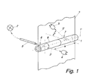
- the optical measuring arrangement shown in FIG. 1 has a capillary 1 with an axis 1 ' on, the sample to be measured being present inside the capillary, or this as part flows through an extracorporeal circuit.
- the measuring radiation is based on a Light source 2, for example, radially radiated into capillary 1 via a light guide 3, see above that the axis 3 'of the measuring radiation is substantially perpendicular to the axis 1' of the capillary 1 is directed.
- a first detector 4 is arranged to detect the transmission radiation.
- the first 4 and the second detector 5 on different Sides of a plane lie ⁇ , which contains the capillary axis 1 'and on the axis 3' of Measuring radiation is normal.
- the optical axis 5 'of the second detector 5 also stands up the capillary axis 1 'is essentially perpendicular, but can be to the axis 3' of the measuring radiation have an angle ⁇ , which can be up to ⁇ 80 °.
- preferred variants are in which the optical axis 5 'of the second detector 5 to the axis 3' of Measuring radiation is aligned essentially parallel.
- the outer wall of the capillary 1 also has Exception of the coupling-in area 6 for the measuring radiation and the coupling-out area 7 for the scattered radiation has a reflective coating 8 or a dichroic coating.
- the capillary can be steamed with aluminum, for example, in the coupling and decoupling areas 6 and 7 ring-shaped areas of approx. 2mm width remain unreflected.
- the measurement radiation is defined in the capillary 1 at a right angle Aperture irradiated in such a way that overexposure to the outer contour of the capillary is avoided becomes.
- the light interacts with the absorbing scattering bodies of the sample, i.e. it is partly absorbed and partly scattered regardless of the direction.
- a part of Measuring radiation reaches the detector 4 directly, which contains the transmission radiation detected.
- Part of the scattered light spreads in the sample, with radiation components, which enter the wall of the capillary 1 either by means of total reflection (see design variant Fig. 3) or due to the mirroring 8 of the outer surface again in the Enter rehearsal.
- a relatively long interaction zone is thus formed along the route a from within which multiple dispersions are possible.
- the scattered radiation is then by the detector 5, which is also arranged perpendicular to the capillary axis 1 ', with a defined Aperture detected.
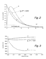
- H 2 O denotes the blank value of the measuring arrangement when the capillary is filled with water
- S g denotes a weighted sum signal of the intensity values T and S.
- the transmission detector 4 delivers a signal curve dependent on the concentration, which, similar to Lambert Beer's law, results in a continuous, monotonically falling measurement curve T.
- the scatter detector 5, supplies a measurement curve S which results from the superimposition of diffuse light scattering and absorption results. With increasing concentration of the sample ingredients the intensity value rises rapidly to a maximum at approx. 2-3 g / dl and falls then continuously with increasing concentration.
- the arrangement according to the invention is particularly suitable for measuring this problem in to get a grip.
- the concentration of the sample is above the Cross-section of the capillary viewed inhomogeneously.
- T of the transmission detector does this mean that the measured intensity increases because of the separation and the nonlinear characteristic curve the mean absorption decreases.
- the measurement signal decreases in the scattering channel because it is in the "thinner” part of the sample fewer scattering bodies are present and the absorption increases in the "denser" part.
- the two measurement signals T and S can be combined, for example, to form a weighted sum signal S g .
- the weighted sum signal for example human blood with a tHb of 5 g / dl
- the weighted sum signal has a constant value in a measurement window of approximately 20 s to 50 s, so that drift-free measurements at several wavelengths are possible.
- Another advantage given by this arrangement is that one can by selected weighting of the signals T and S a sum signal with different Sensitivity curve related to the concentration to be measured. This Property can be used particularly advantageously when measuring whole blood samples.
- tHb content 3 ⁇ tHb ⁇ 5 g / dl
- the measuring range can be reduced to lower concentrations by combining the signals can be expanded considerably without the problem of an ambiguous signal interpretation (Maximum of the scatter signal S).
- the transmission signal and the scatter signal for a special Specimen type e.g. human blood
- a special Specimen type e.g. human blood
- other types e.g. cattle blood
- the light-guiding mechanism in the scattering geometry is related to its behavior changed so significantly in the transmission geometry that a clear differentiation Rehearsal is possible.
- Other disturbances such as Dyes not in the Sample should be included are recognizable when the functional dependency of the two Measurement functions is changed sufficiently.
- the optical axis 5 ' lies of the second detector 5 parallel to the axis 3 'of the measuring radiation.
- the level ⁇ is in this Representation perpendicular to the image plane and coincides with the capillary axis 1 '.
- the capillary 1 is arranged in a bore 9 of a measuring block 10, which also receives the light guide 3 and the aperture 11 for the transmission detector 4 and the aperture 12 for the scattered light detector 5 are defined.
- a Optical separating element 13 is arranged, which the annular gap 14 between the capillary 1st and covers the bore 9.
- the optical separating element 13 can for example be an O-ring made of black rubber and arranged in a groove of the bore 9.
- the Separating element effectively prevents false light from being injected into the scattered light detector 5 and serves at the same time for centering the capillary 1 in the bore 9.
- the capillary 1 are fixed by sealing elements 15, which the capillary on the input and output side connect to inlet and outlet lines 16 and 17 for the sample medium.
- the mechanism of action can thereby be improved that the bore 9 of the measuring block 10 at least between the Coupling area 6 and coupling area 7 a diffusely reflecting surface 18 having. It turns out that such a surface design brings the best results because no preferred direction for the back reflection in the sample arises, which means one Execution less sensitive to local inhomogeneities than mirrored surfaces.
- the first detector 4 in Transmission geometry records changes in the intensity of the light source as well as coupling losses the measuring radiation when entering the capillary 1.
- the blank value measurement at second detector 5 in scattered light geometric gives additional information about changes inside the measuring capillary, for example dirt or deposits as well over the decoupling area of the capillary. Both blank measurements are preferred carried out synchronously in order to fluctuations in the intensity of the light source during the To compensate for reference measurement.
- the course of the measurement function of the scattered light detector 5 can be specific Requirements are adjusted. For example, the position of the maximum or Reversal point (see Fig. 2) so that this is below the expected minimum concentration of the sample to be measured is safe and thus ambiguous measurement results be avoided. Also the mean steepness or the steepness course over the interested Measuring range can be adapted and optimized within certain limits.
- the capillary 1 When measuring tHb and S02 in a whole blood sample, the capillary 1 typically points an inner diameter of approx. 1.1 to 1.6 mm and the distance a between the coupling area 6 and the decoupling area 7 is approximately 4 to 10 mm.
- the light guide 3 has a core diameter of approx. 1 mm, the aperture 11 or 12 is approx. 1.5 to 2.5 mm.
- Another advantage of the measurement function shown in FIG. 2 or its adaptation to the specific one Requirements is that the maximum intensity of the scattered radiation at a defined minimum sample concentration is reached and the entire dynamic measuring range the arrangement can be used for the entire concentration range. So that is also give the best use of the resolution achievable by the detection system. This is particularly advantageous if the medium to be measured is strongly absorbed, not diluted should be difficult or due to fluidic reasons difficult in a sufficiently thin Cell can be filled. This is especially true for biological fluid in particular Whole blood too.
- the intensity is plotted on the ordinate and the concentration in g / dl on the abscissa.
- 5 shows the course of the intensity of the transmission radiation (detector 4) for a capillary with an air gap (unmirrored) and for a mirrored capillary.
- 6 shows the intensity curve (amplified by a factor of 100) for the scattered light detector (detector 5) for both variants (mirrored and non-mirrored), the blank value (H 2 O mirrored or H 2 O non-mirrored) for one for both variants capillary filled with water is entered.
Abstract
Description
Die Erfindung betrifft eine optische Messanordnung zur Bestimmung der Transmissions- und der Streustrahlung einer mit einer Messstrahlung beaufschlagten, in einer Kapillare vorliegenden, flüssigen Probe, wobei die Achse der Messstrahlung im wesentlichen senkrecht auf die Achse der Kapillare gerichtet ist, mit einem ersten Detektor zur Erfassung der Transmissionsstrahlung, welcher im Bereich der Achse der Messstrahlung angeordnet ist sowie mit einem in Richtung der Kapillarachse mit einem Abstand vom ersten Detektor angeordneten zweiten Detektor zur Erfassung der Streustrahlung.The invention relates to an optical measuring arrangement for determining the transmission and the scattered radiation of a measuring radiation which is present in a capillary, liquid sample, the axis of the measuring radiation being substantially perpendicular to the Axis of the capillary is directed, with a first detector for detecting the transmission radiation, which is arranged in the area of the axis of the measuring radiation and with an in Direction of the capillary axis at a distance from the first detector arranged second Scattered radiation detector.
Derartige Messanordnungen werden vor allem für die Untersuchung flüssiger Medien verwendet, welche absorbierende Streukörper beinhalten. Es sind dies z.B. Vollblutproben, andere organische oder anorganische Flüssigkeiten, aber auch flüssige Proben in der Umwelttechnologie, wie z.B. Abwasserproben.Such measuring arrangements are mainly used for the investigation of liquid media, which contain absorbent scattering bodies. These are e.g. Whole blood samples, others organic or inorganic liquids, but also liquid samples in the Environmental technology, such as Sewage samples.
Zur Bestimmung der Konzentration der Inhaltsstoffe derartiger Flüssigkeiten können Absorptionsmessungen bei unterschiedlichen Wellenlängen in einer Transmissions- bzw. Durchlichtgeometrie und in einer Streulichtgeometrie durchgeführt werden, wobei aus den gemessenen Transmissions- und Streulichtintensitäten unter Zuhilfenahme von Kalibrierdaten bekannter Proben und der Kenntnis der Leerwerte (Messwerte bei mit reinem Wasser gefüllter Kapillare) die Inhaltsstoffe bestimmt werden können.Absorption measurements can be used to determine the concentration of the ingredients of such liquids at different wavelengths in a transmission or transmitted light geometry and be carried out in a scattered light geometry, from the measured Transmission and scattered light intensities using known calibration data Samples and knowledge of the blank values (measured values when the capillary is filled with pure water) the ingredients can be determined.
So ist beispielsweise aus der EP 0 800 074 A1 eine Vorrichtung zur Bestimmung der Konzentration
von Hämoglobinderivaten in einer unverdünnten unhämolisierten Vollblutprobe
bekannt geworden. Die Vollblutprobe wird in einer Küvette mit der Messstrahlung beaufschlagt,
welche zumindest n monochromatische, schmalbandige Strahlungsanteile unterschiedlicher
Wellenlänge aufweist. Eine erste Detektionseinrichtung ist in Transmissionsgeometrie
auf der Achse des Primärstrahles angeordnet. Der Detektor weist eine relativ kleine
Strahleintrittsfläche auf und mißt im wesentlichen Strahlung aus dem Zentralstrahl. In einer
zweiten Messposition in einem bestimmten Winkel zur Achse des Primärstrahles ist eine
zweite Detektionseinrichtung zur Erfassung der Streustrahlung angeordnet. Beide Detektoren
stehen über Signalleitungen mit einer Auswerteeinrichtung in Verbindung, mit welcher die
Hämoglobinderivate mittels einer abgespeicherten Kalibriermatrix berechnet werden.For example,
Aus der EP 0 720 013 A2 ist ein Verfahren und eine Vorrichtung zur optischen Bestimmung
von Blutparametern bekannt geworden, wobei eine Ausführungsvariante eine in einem Gehäuse
angeordnete Durchflusszelle zeigt, welche die Blutprobe aufnimmt. Senkrecht auf die
Achse der Durchflusszelle wird eine Messstrahlung aus einer Lichtquelle eingekoppelt, wobei
auf der anderen Seite der Messzelle ein erster Detektor in einer Durchlichtgeometrie und weitere
Detektoren in unterschiedlichem Abstand vom ersten Detektor jeweils in einer Streulichtgeometrie
angeordnet sind. Die Messzelle der beschriebenen Anordnung kann direkt an den
extrakorporalen Blutkreislauf angeschlossen und zur Optimierung der Dialyse verwendet
werden.
Weiters ist aus der US 4,745,279 A eine Vorrichtung zur Hämatokrit-Messung in Blut bekannt geworden, bei welcher Infrarotstrahlung in eine transparente Küvette, durch welche das Blut geführt wird, eingestrahlt wird. Ein erster, am Boden der Küvette angeordneter Detektor empfängt diffus gestreutes Licht aus der Probe, welches ein Maß für die Sauerstoffsättigung darstellt. Ein zweiter, an einer Seitenfläche der Küvette angeordneter Detektor dient zur Hämatokrit-Messung. Das Anregungslicht für beide Detektoren wird durch zwei unterschiedliche Lichtquellen (LEDs) zur Verfügung gestellt, welche jeweils paarweise im Bereich der Detektoren angeordnet sind. Eine dritte Lichtquelle, welche die Probe nicht beaufschlagt, dient mit einem weiteren Detektor zur Erzeugung eines Referenzsignals.Furthermore, a device for measuring hematocrit in blood is known from US Pat. No. 4,745,279 with which infrared radiation in a transparent cuvette through which the Blood is led, is irradiated. A first detector located on the bottom of the cuvette receives diffusely scattered light from the sample, which is a measure of the oxygen saturation represents. A second detector, which is arranged on one side surface of the cuvette, is used for hematocrit measurement. The excitation light for both detectors is provided by two different ones Light sources (LEDs) are provided, each in pairs in the area of Detectors are arranged. A third light source, which does not act on the sample, is used with another detector to generate a reference signal.
Eine Messanordnung der eingangs beschriebenen Art ist beispielsweise aus der EP 0 575 712 A2 bekannt, mit welcher direkt in-vitro oder in einer extrakorporalen Blutzirkulation gleichzeitig der Hämatokritwert und eine weitere Größe, beispielsweise die Natriumkonzentration bestimmt werden kann. Der kollimierte Messstrahl aus einer Lichtquelle trifft dabei senkrecht auf eine von der Blutprobe durchflossene Messkammer, welche in einem Gehäuse angeordnet ist. Zur Absorptionsmessung werden zwei Fotodetektoren verwendet, wobei der erste Detektor in Richtung des einfallenden Lichtes (Transmissionsstrahlung) und der zweite abseits von der zentralen Richtung (Streustrahlung) positioniert ist. Die vom zweiten Detektor erfassten Strahlungsanteile werden stark von der Natriumkonzentration beeinflusst, sodass deren quantitative Bestimmung möglich ist.A measuring arrangement of the type described at the outset is, for example, from US Pat EP 0 575 712 A2 known, with which directly in-vitro or in an extracorporeal blood circulation at the same time the hematocrit value and another variable, for example the sodium concentration can be determined. The collimated measuring beam from a light source hits perpendicular to a measuring chamber through which the blood sample flows, which is in a housing is arranged. Two photodetectors are used for absorption measurement, whereby the first detector in the direction of the incident light (transmission radiation) and the second is positioned away from the central direction (scattered radiation). The second Radiation components detected by the detector are strongly influenced by the sodium concentration, so that their quantitative determination is possible.
Da die Intensität der Transmissionsstrahlung weit größer (Faktor 100) als jene der Streustrahlung ist, kann bei den bekannten Messanordnungen eine nachteilige Beeinflussung des Streulichtdetektors durch die Messstrahlung nicht vermieden werden. Die Messstrahlung kann zumindest teilweise durch Streu- und Reflexionsprozesse außerhalb der Probe sowie zum Teil direkt in den Streulichtdetektor gelangen und dessen Messergebnis verfälschen.Because the intensity of the transmission radiation is far greater (factor 100) than that of the scattered radiation is, in the known measuring arrangements can adversely affect the scattered light detector cannot be avoided by the measuring radiation. The measuring radiation can at least partly through scattering and reflection processes outside the sample and partly get directly into the scattered light detector and falsify its measurement result.
Aufgabe der vorliegenden Erfindung ist es, eine Messanordnung der eingangs beschriebenen Art derart weiterzubilden, daß ein möglichst aussagekräftiges, von der Primärstrahlung unbeeinflusstes Messsignal beim Streulichtdetektor erfaßt werden kann.The object of the present invention is to provide a measuring arrangement as described in the introduction Kind in such a way that a meaningful as possible, unaffected by the primary radiation Measurement signal at the scattered light detector can be detected.
Diese Aufgabe wird erfindungsgemäß dadurch gelöst, daß der erste und der zweite Detektor auf unterschiedlichen Seiten einer Ebene liegen, welche die Kapillarachse enthält und auf die Achse der Messstrahlung normal steht. Die Messung der Streustrahlung erfolgt somit - im Unterschied zum Stand der Technik - in einer Rückstreuposition, sodass allein aufgrund der geometrischen Anordnung eine Beeinflussung des Streulichtdetektors durch die Messstrahlung weitgehend ausgeschlossen ist. Durch diese Maßnahme kann der Intensitätswert für die Leermessung (mit Wasser gefüllte Kapillare) sehr gering gehalten werden, sodass ein großer analytischer Messbereich zur Verfügung steht. Bei der eigentlichen Probenmessung tritt die Messstrahlung in Wechselwirkung mit den Streukörpern des Probenmediums, d.h. sie wird teilweise absorbiert und teilweise richtungsunabhängig gestreut. Ein Teil des Streulichtes breitet sich dabei in Richtung des zweiten Detektors (Streulichtdetektor) aus, ein Teil gelangt zur Wand bzw. in die Wand der Kapillare, welche als Lichtleitelement wirkt, und einen Teil dieser Strahlung wieder in die Probe einkoppelt, wodurch dieser Anteil für weitere Streuprozesse zur Verfügung steht. Durch diese Maßnahme kann sich die Messstrahlung entlang einer relativ langen Wechselwirkungszone in Richtung des Streulichtdetektors ausbreiten, wo sie als Streustrahlung durch den senkrecht zur Kapillarachse angeordneten zweiten Detektor registriert wird.This object is achieved in that the first and the second detector lie on different sides of a plane which contains the capillary axis and on which Axis of the measuring radiation is normal. Scattered radiation is thus measured - in Difference from the prior art - in a backscatter position, so that solely due to the geometric arrangement an influence of the scattered light detector by the measuring radiation is largely excluded. This measure allows the intensity value for the Empty measurement (water filled capillary) can be kept very low, so that a large analytical measuring range is available. During the actual sample measurement, the Measuring radiation in interaction with the scattering bodies of the sample medium, i.e. she will partly absorbed and partly scattered regardless of direction. Part of the stray light spreads in the direction of the second detector (scattered light detector), some reaches to the wall or in the wall of the capillary, which acts as a light guiding element, and a part This radiation couples back into the sample, which means that this portion for further scattering processes is available. This measure allows the measuring radiation to move along a spread relatively long interaction zone towards the scattered light detector, where it registered as scattered radiation by the second detector arranged perpendicular to the capillary axis becomes.
In einer bevorzugten Ausführungsvariante ist die optische Achse des zweiten Detektors zur Achse der Messstrahlung im wesentlichen parallel angeordnet. Obwohl auch beträchtliche Abweichungen zur parallelen Anordnung (zirka ± 80°) brauchbare Messergebnisse liefern, solange der Streulichtdetektor in einer Rückstreugeometrie angeordnet ist, können naturgemäß die besten Ergebnisse in der 0°-Position erreicht werden (siehe Ausführungsvariante Fig. 4).In a preferred embodiment variant, the optical axis of the second detector is closed Axis of the measuring radiation arranged essentially parallel. Though considerable too Deviations from the parallel arrangement (approx. ± 80 °) provide usable measurement results, of course, as long as the scattered light detector is arranged in a backscatter geometry the best results are achieved in the 0 ° position (see variant Fig. 4).
Für die optische Leitfähigkeit der Kapillarwand sorgt in einer Ausführungsvariante ein optisch dünneres Medium (z.B. Luft) an der Außenwand der Kapillare. Falls die Kapillare in einer Bohrung eines Messblockes angeordnet ist, wird erfindungsgemäß zwischen einem Einkoppelbereich für die Messstrahlung und einem Auskoppelbereich für die Streustrahlung zumindest ein optisches Trennelement angeordnet, welches einen Ringspalt zwischen der Kapillare und der Bohrung abdeckt. Damit wird verhindert, daß Teile der Messstrahlung durch Spiegelungen und Reflexionen bzw. Luftstreuung außerhalb der Kapillare in den Bereich des zweiten Detektors gelangen.In one embodiment, an optical ensures the optical conductivity of the capillary wall thinner medium (e.g. air) on the outer wall of the capillary. If the capillary is in a Bore of a measuring block is arranged according to the invention between a coupling area for the measuring radiation and a decoupling area for the scattered radiation at least an optical separating element is arranged, which has an annular gap between the capillary and covers the hole. This prevents parts of the measuring radiation from being reflected and reflections or air scatter outside the capillary in the area of the second Detector.
Besonders vorteilhaft ist es in diesem Zusammenhang, das optische Trennelement als O-Ring oder Quadring auszuführen, welcher die Kapillare in der Bohrung des Messblockes zentriert.In this context, it is particularly advantageous to use the optical separating element as an O-ring or quad ring, which centers the capillary in the bore of the measuring block.
Es hat sich weiters gezeigt, daß die Signalgüte beim Streulichtdetektor weiter erhöht werden kann, wenn die Bohrung des Messblockes zumindest zwischen dem Einkoppelbereich und dem Auskoppelbereich eine diffus reflektierende Oberfläche aufweist.It has also been shown that the signal quality in the scattered light detector is further increased can, if the bore of the measuring block at least between the coupling area and the decoupling area has a diffusely reflecting surface.
In einer weiteren vorteilhaften Ausführungsvariante der Erfindung ist vorgesehen, daß die Außenwand der Kapillare mit Ausnahme des Einkoppelbereiches für die Messstrahlung und des Auskoppelbereiches für die Streustrahlung verspiegelt ist, oder eine dichroitische Beschichtung aufweist.In a further advantageous embodiment of the invention it is provided that the Outer wall of the capillary with the exception of the coupling area for the measuring radiation and of the coupling-out area is mirrored for the scattered radiation, or a dichroic coating having.
Die Erfindung wird im folgenden anhand von zum Teil schematischen Zeichnungen näher erläutert.
- Fig. 1
- zeigt eine schematische Darstellung der erfindungsgemäßen Messanordnung zur Bestimmung der Transmissions- und der Streustrahlung einer flüssigen Proben,
- Fig. 2
- ein Diagramm des Intensitätsverlaufes bei steigender Konzentration eines Probeninhaltsstoffes für den Transmissions- und den Streulichtdetektor der Messanordnung,
- Fig. 3
- ein Diagramm, welches die Änderungen des Intensitätsverlaufes während der Messzeit zeigt,
- Fig. 4
- eine bevorzugte Ausführungsvariante der Erfindung, sowie die
- Fig. 5
- (Transmissionsstrahlung) und 6 (Streustrahlung) Diagramme über den Intensitätsverlauf bei steigender Konzentration eines Probeninhaltsstoffes.
- Fig. 1
- shows a schematic representation of the measuring arrangement according to the invention for determining the transmission and scattered radiation of a liquid sample,
- Fig. 2
- 2 shows a diagram of the intensity curve with increasing concentration of a sample constituent for the transmission and the scattered light detector of the measuring arrangement,
- Fig. 3
- a diagram which shows the changes in the intensity curve during the measurement time,
- Fig. 4
- a preferred embodiment of the invention, and the
- Fig. 5
- (Transmission radiation) and 6 (scattered radiation) diagrams of the intensity curve with increasing concentration of a sample ingredient.
Die in Fig. 1 dargestellt optische Messanordnung weist eine Kapillare 1 mit einer Achse 1'
auf, wobei die zu vermessende Probe im Inneren der Kapillare vorliegt, bzw. diese als Teil
eines extrakorporalen Kreislaufes durchströmt. Die Messstrahlung wird ausgehend von einer
Lichtquelle 2 beispielsweise über einen Lichtleiter 3 in die Kapillare 1 radial eingestrahlt, so
daß die Achse 3' der Messstrahlung im wesentlichen senkrecht auf die Achse 1' der Kapillare
1 gerichtet ist. Auf der gegenüber liegenden Seite der Kapillare ist im Bereich der Achse 3'
der Messstrahlung ein erster Detektor 4 zur Erfassung der Transmissionsstrahlung angeordnet.
In einem Abstand a in Richtung der Kapillarachse 1' ist ein zweiter Detektor 5 zur Erfassung
der Streustrahlung angeordnet, wobei der erste 4 und der zweite Detektor 5 auf unterschiedlichen
Seiten einer Ebene ε liegen, welche die Kapillarachse 1' enthält und auf die Achse 3' der
Messstrahlung normal steht. Die optisch Achse 5' des zweiten Detektors 5 steht ebenfalls auf
die Kapillarachse 1' im wesentlichen senkrecht, kann jedoch zur Achse 3' der Messstrahlung
einen Winkel α aufweisen, welcher bis ±80° betragen kann. Bevorzugt sind allerdings Ausführungsvarianten,
bei welchen die optische Achse 5' des zweiten Detektors 5 zur Achse 3' der
Messstrahlung im wesentlichen parallel ausgerichtet ist.The optical measuring arrangement shown in FIG. 1 has a
Bei der in Fig. 1 dargestellten Ausführungsvariante weist die Außenwand der Kapillare 1 mit
Ausnahme des Einkoppelbereiches 6 für die Messstrahlung und des Auskoppelbereiches 7 für
die Streustrahlung eine Verspiegelung 8 oder eine dichroitische Beschichtung auf. Die Kapillare
kann beispielsweise mit Aluminium bedampft werden, wobei in den Ein- und Auskoppelbereichen
6 und 7 ringförmige Bereiche von ca. 2mm Breite unverspiegelt bleiben.In the embodiment variant shown in FIG. 1, the outer wall of the
Bei der Messung wird die Messstrahlung in die Kapillare 1 unter rechtem Winkel bei definierter
Apertur derart eingestrahlt, daß ein Überstrahlen der äußeren Kontur der Kapillare vermieden
wird. Das Licht tritt in Wechselwirkung mit den absorbierenden Streukörpern der Probe,
d.h. es wird teilweise absorbiert und teilweise richtungsunabhängig gestreut. Ein Teil der
Messstrahlung gelangt auf direktem Wege zum Detektor 4, welcher die Transmissionsstrahlung
erfaßt. Ein Teil des Streulichtes breitet sich in der Probe aus, wobei Strahlungsanteile,
welche in die Wand der Kapillare 1 eintreten entweder mittels Totalreflexion (siehe Ausführungsvariante
Fig. 3) oder aufgrund der Verspiegelung 8 der äußeren Oberfläche wieder in die
Probe eintreten. Entlang der Strecke a bildet sich somit eine relativ lange Wechselwirkungszone
aus, innerhalb welcher Mehrfachstreuungen möglich sind. Die Streustrahlung wird dann
durch den ebenfalls zur Kapillarachse 1' senkrecht angeordneten Detektor 5 mit definierter
Apertur detektiert.During the measurement, the measurement radiation is defined in the
In Fig. 2 sind die normierten intensitätswerte T (Transmissionsdetektor 4) bzw. S (Streudetektor 5) in Abhängigkeit der Konzentration des streuenden Mediums in der Probe (beispielsweise der Hämoglobinkonzentration in Vollblut in g/dl) aufgetragen. Mit H2O ist der Leerwert der Messanordnung bei mit Wasser gefüllter Kapillare gekennzeichnet, mit Sg ein gewichtetes Summensignal der Intensitätswerte T und S.2 shows the normalized intensity values T (transmission detector 4) and S (scatter detector 5) as a function of the concentration of the scattering medium in the sample (for example the hemoglobin concentration in whole blood in g / dl). H 2 O denotes the blank value of the measuring arrangement when the capillary is filled with water, S g denotes a weighted sum signal of the intensity values T and S.
Der Transmissionsdetektor 4 liefert einen von der Konzentration abhängigen Signalverlauf,
der ähnlich dem Lambert Beer'schen Gesetz eine stetige, monoton fallende Messkurve T ergibt.
Der Streudetektor 5 hingegen liefert eine Messkurve S, die aus der Überlagerung von
diffuser Lichtstreuung und Absorption resultiert. Bei steigender Konzentration der Probeninhaltsstoffe
steigt der Intensitätswert rasch zu einem Maximum bei ca. 2-3 g/dl an und fällt
dann kontinuierlich mit steigender Konzentration ab.The
Eine Vielzahl von Proben weisen die Messtechnisch unangenehme Eigenschaft auf, daß die Streukörper während der Messzeit abzusinken beginnen, falls die Probe nicht ausreichend bewegt werden kann. Dieser Effekt bedingt eine Drift der detektierten Signale und kann zu Fehlmessungen führen.A large number of samples have the metrologically unpleasant property that the If the sample is not sufficient, the scattering bodies begin to sink during the measuring time can be moved. This effect causes a drift of the detected signals and can Lead to incorrect measurements.
Die erfindungsgemäße Anordnung ist besonders geeignet, dieses Problem Messtechnisch in den Griff zu bekommen.The arrangement according to the invention is particularly suitable for measuring this problem in to get a grip.
Tritt eine Sedimentation der Streukörper ein, so wird die Konzentration der Probe über den Querschnitt der Kapillare betrachtet inhomogen. Für das Signal T des Transmissionsdetektors bedeutet das, daß die gemessene Intensität zunimmt, weil durch die Entmischung und die nichtlineare Kennlinie die mittlere Absorption abnimmt.If sedimentation of the scattering bodies occurs, the concentration of the sample is above the Cross-section of the capillary viewed inhomogeneously. For the signal T of the transmission detector does this mean that the measured intensity increases because of the separation and the nonlinear characteristic curve the mean absorption decreases.
Im Gegensatz dazu nimmt im Streukanal das Messsignal ab weil im "dünneren" Teil der Probe weniger Streukörper vorhanden sind und im "dichteren" Teil die Absorption zunimmt.In contrast, the measurement signal decreases in the scattering channel because it is in the "thinner" part of the sample fewer scattering bodies are present and the absorption increases in the "denser" part.
Werden nun beide Signale, das vom Streudetektor und das vom Transmissionsdetektor, in geeigneter Weise kombiniert, kompensieren sich in erster Ordnung die Einzelfehler so daß das resultierende Signal innerhalb der Messzeit weitgehend driftfrei zur Verfügung steht. Dadurch kann die Integrationszeit verlängert und das Signal/Rauschverhältnis verbessert werden.If both signals, that from the scatter detector and that from the transmission detector, are now in combined appropriately, the individual errors compensate in the first order so that resulting signal is largely drift-free within the measurement time. Thereby the integration time can be extended and the signal / noise ratio can be improved.
Die beiden Messsignale T und S können beispielsweise zu einem gewichteten Summensignal Sg kombiniert werden. Wie aus Fig. 3 ersichtlich, weist das gewichtete Summensignal (z.B. Humanblut mit einem tHb von 5g/dl) in einem Messfenster von ca. 20s bis 50s einen konstanten Wert auf, so daß driftfreie Messungen bei mehreren Wellenlängen möglich sind.The two measurement signals T and S can be combined, for example, to form a weighted sum signal S g . As can be seen from FIG. 3, the weighted sum signal (for example human blood with a tHb of 5 g / dl) has a constant value in a measurement window of approximately 20 s to 50 s, so that drift-free measurements at several wavelengths are possible.
Ein weiterer durch diese Anordnung gegebener Vorteil liegt darin, daß man durch entsprechend gewählte Gewichtung der Signale T und S ein Summensignal mit unterschiedlichem Empfindlichkeitsverlauf bezogen auf die zu messende Konzentration erzeugen kann. diese Eigenschaft läßt sich besonders vorteilhaft bei der Messung von Vollblutproben nützen. Bei Blutproben mit sehr niederem tHb Gehalt (3 < tHb < 5 g/dl) ist eine gesteigerte Messgenauigkeit wünschenswert um die medizinische Entscheidung, ob z.B. dem Patient eine Infusion oder eine Transfusion verabreicht werden soll, sicher treffen zu können. Wie aus Fig. 2 ersichtlich, kann durch die Kombination der Signale der Messbereich zu niedereren Konzentrationen beträchtlich erweitert werden ohne auf das Problem einer zweideutigen Signalinterpretation (Maximum des Streusignals S) zu stoßen. Another advantage given by this arrangement is that one can by selected weighting of the signals T and S a sum signal with different Sensitivity curve related to the concentration to be measured. this Property can be used particularly advantageously when measuring whole blood samples. At Blood samples with a very low tHb content (3 <tHb <5 g / dl) is an increased measuring accuracy desirable for the medical decision whether e.g. the patient an infusion or if a transfusion is to be administered. As can be seen from Fig. 2, the measuring range can be reduced to lower concentrations by combining the signals can be expanded considerably without the problem of an ambiguous signal interpretation (Maximum of the scatter signal S).
Ein weiterer Vorteil liegt darin, daß das Transmissionssignal und das Streusignal für eine spezielle Probenart (z.B. Humanblut) in einem definierten Zusammenhang bezüglich Kurvenverlauf stehen. Dadurch ist es möglich Proben anderer Art (z.B. Rinderblut) zu erkennen und zu diskriminieren. Obwohl Human- und Rinderblut ein sehr ähnliches Absorptionsverhalten zeigen, unterscheiden sich diese Proben durch die Größe der roten Blutzellen (= Streuzentren). Dadurch wird der Lichtleitmechanismus in der Streugeometrie im Verhältnis zum Verhalten in der Transmissionsgeometrie so signifikant geändert, daß eine klare Unterscheidung unterschiedlicher Proben möglich ist. Auch andere Störgrößen wie z.B. Farbstoffe, die nicht in der Probe enthalten sein sollten, sind erkennbar, wenn die funktionale Abhängigkeit der beiden Messfunktionen ausreichend verändert ist.Another advantage is that the transmission signal and the scatter signal for a special Specimen type (e.g. human blood) in a defined context with regard to curve shape stand. This makes it possible to recognize and close samples of other types (e.g. cattle blood) discriminate. Although human and bovine blood show a very similar absorption behavior, these samples differ in the size of the red blood cells (= scattering centers). As a result, the light-guiding mechanism in the scattering geometry is related to its behavior changed so significantly in the transmission geometry that a clear differentiation Rehearsal is possible. Other disturbances such as Dyes not in the Sample should be included are recognizable when the functional dependency of the two Measurement functions is changed sufficiently.
Bei der in Fig. 4 dargestellten, bevorzugten Ausführungsvariante liegt die optische Achse 5'
des zweiten Detektors 5 parallel zur Achse 3' der Messstrahlung. Die Ebene ε steht in dieser
Darstellung senkrecht auf die Bildebene und fällt mit der Kapillarachse 1' zusammen. Bei
dieser Ausführungsvariante ist die Kapillare 1 in einer Bohrung 9 eines Messblockes 10 angeordnet,
welcher weiters den Lichtleiter 3 aufnimmt und die Apertur 11 für den Transmissionsdetektor
4 sowie die Apertur 12 für den Streulichtdetektor 5 definiert. Zwischen dem Einkoppelbereich
6 für die Messstrahlung und dem Auskoppelbereich 7 für die Streustrahlung ist ein
optisches Trennelement 13 angeordnet, welches den Ringspalt 14 zwischen der Kapillare 1
und der Bohrung 9 abdeckt. Das optische Trennelement 13 kann beispielsweise als O-Ring
aus schwarzem Gummi ausgeführt und in einer Nut der Bohrung 9 angeordnet sein. Das
Trennelement verhindert wirksam die Einkoppelung von Fehllicht in den Streulichtdetektor 5
und dient gleichzeitig zur Zentrierung der Kapillare 1 in der Bohrung 9. Weiters kann die Kapillare
1 durch Dichtelemente 15 fixiert werden, welche die Kapillare ein- und ausgangsseitig
mit Zu- und Abflußleitungen 16 und 17 für das Probenmedium verbinden.In the preferred embodiment variant shown in FIG. 4, the optical axis 5 'lies
of the
Bei der Ausführungsvariante mit Luftspalt 14 gemäß Fig. 4 kann der Wirkmechanismus dadurch
verbessert werden, daß die Bohrung 9 des Messblockes 10 zumindest zwischen dem
Einkoppelbereich 6 und dem Auskoppelbereich 7 eine diffus reflektierende Oberfläche 18
aufweist. Es zeigt sich, daß eine derartige Oberflächengestaltung beste Ergebnisse bringt, da
keine Vorzugsrichtung für die Rückreflexion in die Probe entsteht, wodurch eine derartige
Ausführung unempfindlicher auf lokale Inhomogenitäten reagiert als verspiegelte Oberflächen.In the embodiment variant with an
Um einen Leerwert der Messanordnung zu bestimmen, durch welchen Intensitätsänderungen
der Messstrahlung und Veränderungen im optischen Weg kompensiert werden können, werden
zwei Messungen bei mit Wasser gefüllter Kapillare durchgeführt. Der erste Detektor 4 in
Transmissionsgeometrie erfaßt dabei Änderungen der Intensität der Lichtquelle sowie Einkoppelverluste
der Messstrahlung beim Eintritt in die Kapillare 1. Die Leerwertmessung beim
zweiten Detektor 5 in Streulichtgeometric gibt zusätzliche Informationen über Veränderungen
im Inneren der Messkapillare, beispielweise Verschmutzungen oder Belagsbildungen sowie
über den Auskoppelbereich der Kapillare. Beide Leerwertmessungen werden vorzugsweise
zeitlich synchron durchgeführt, um Schwankungen der Intensität der Lichtquelle während der
Referenzmessung zu kompensieren. In order to determine a blank value of the measurement arrangement, by means of which changes in intensity
the measuring radiation and changes in the optical path can be compensated
two measurements were carried out with a capillary filled with water. The
Durch Anpassen der optisch relevanten Parameter wie Kapillardurchmesser, Kapillarwandstärke,
Länge der Distanz a zwischen Einkoppelbereich 6 und Auskoppelbereich 7 (Wechselwirkungszone)
optische Eigenschaften der Bohrung 9, Apertur der Ein- und Auskoppelgeometrie
etc. kann der Verlauf der Messfunktion des Streulichtdetektors 5 an die spezifischen
Erfordernisse angepaßt werden. Beispielsweise kann damit die Lage des Maximums bzw.
Umkehrpunktes (siehe Fig. 2) so gelegt werden, daß dieses unter der erwarteten Minimalkonzentration
der zu vermessenden Probe liegt und damit zweideutige Messergebnisse sicher
vermieden werden. Auch die mittlere Steilheit bzw. der Steilheitsverlauf über den interessierten
Messbereich kann innerhalb gewisser Grenzen angepaßt und optimiert werden.By adjusting the optically relevant parameters such as capillary diameter, capillary wall thickness,
Length of the distance a between
Bei der Messung von tHb und S02 in einer Vollblutprobe weist die Kapillare 1 typischerweise
einen Innendurchmesser von ca. 1,1 bis 1,6 mm auf und die Distanz a zwischen dem Einkoppelbereich
6 und dem Auskoppelbereich 7 beträgt ca. 4 bis 10 mm. Der Lichtleiter 3 weist
einen Coredurchmesser von ca. 1 mm auf, die Apertur 11 bzw. 12 beträgt ca. 1,5 bis 2,5 mm.When measuring tHb and S02 in a whole blood sample, the
Ein weiterer Vorteil der in Fig. 2 gezeigten Messfunktion bzw. deren Anpassung an die spezifischen Erfordernisse liegt darin, daß die maximale Intensität der Streustrahlung bei einer definierten minimalen Probenkonzentration erreicht wird und der gesamte dynamische Messbereich der Anordnung für den gesamten Konzentrationsbereich genutzt werden kann. Damit ist auch die beste Ausnutzung der durch das Detektionssystem erreichbaren Auflösung gegeben. Dies ist besonders vorteilhaft, wenn das zu messende Medium stark absorbiert, nicht verdünnt werden soll oder aus strömungstechnischen Gründen schwer in eine ausreichend dünne Küvette gefüllt werden kann. Dies trifft vor allem für biologische Flüssigkeit im speziellen für Vollblut zu.Another advantage of the measurement function shown in FIG. 2 or its adaptation to the specific one Requirements is that the maximum intensity of the scattered radiation at a defined minimum sample concentration is reached and the entire dynamic measuring range the arrangement can be used for the entire concentration range. So that is also give the best use of the resolution achievable by the detection system. This is particularly advantageous if the medium to be measured is strongly absorbed, not diluted should be difficult or due to fluidic reasons difficult in a sufficiently thin Cell can be filled. This is especially true for biological fluid in particular Whole blood too.
In den Fig. 5 und 6 ist jeweils auf der Ordinate die Intensität und auf der Abszisse die Konzentration in g/dl aufgetragen. Fig. 5 zeigt den Intensitätsverlauf der Transmissionsstrahlung (Detektor 4) für eine Kapillare mit Luftspalt (unverspiegelt) sowie für eine verspiegelte Kapillare. Fig. 6 zeigt den Intensitätsverlauf (verstärkt um den Faktor 100) für den Streulichtdetektor (Detektor 5) für beide Varianten (verspiegelt und unverspiegelt), wobei für beide Varianten auch der Leerwert (H2O verspiegelt bzw. H2O unverspiegelt) für eine mit Wasser gefüllte Kapillare eingetragen ist.5 and 6, the intensity is plotted on the ordinate and the concentration in g / dl on the abscissa. 5 shows the course of the intensity of the transmission radiation (detector 4) for a capillary with an air gap (unmirrored) and for a mirrored capillary. 6 shows the intensity curve (amplified by a factor of 100) for the scattered light detector (detector 5) for both variants (mirrored and non-mirrored), the blank value (H 2 O mirrored or H 2 O non-mirrored) for one for both variants capillary filled with water is entered.
Claims (6)
Priority Applications (1)
| Application Number | Priority Date | Filing Date | Title |
|---|---|---|---|
| AT00890151T ATE232976T1 (en) | 1999-05-20 | 2000-05-11 | OPTICAL MEASURING ARRANGEMENT FOR DETERMINING TRANSMISSION AND SCATTERED RADIATION |
Applications Claiming Priority (2)
| Application Number | Priority Date | Filing Date | Title |
|---|---|---|---|
| AT0090099A AT406912B (en) | 1999-05-20 | 1999-05-20 | Optical measurement arrangement for determining transmitted and scattered radiation |
| AT90099 | 1999-05-20 |
Publications (3)
| Publication Number | Publication Date |
|---|---|
| EP1054252A2 true EP1054252A2 (en) | 2000-11-22 |
| EP1054252A3 EP1054252A3 (en) | 2001-07-18 |
| EP1054252B1 EP1054252B1 (en) | 2003-02-19 |
Family
ID=3502430
Family Applications (1)
| Application Number | Title | Priority Date | Filing Date |
|---|---|---|---|
| EP00890151A Expired - Lifetime EP1054252B1 (en) | 1999-05-20 | 2000-05-11 | Optical measuring device for the determination of transmitted and scattered radiation |
Country Status (6)
| Country | Link |
|---|---|
| US (1) | US6388752B1 (en) |
| EP (1) | EP1054252B1 (en) |
| JP (1) | JP3318657B2 (en) |
| AT (2) | AT406912B (en) |
| DE (1) | DE50001263D1 (en) |
| ES (1) | ES2188497T3 (en) |
Cited By (2)
| Publication number | Priority date | Publication date | Assignee | Title |
|---|---|---|---|---|
| DE10360563A1 (en) * | 2003-12-22 | 2005-07-14 | BSH Bosch und Siemens Hausgeräte GmbH | Fluid contamination measurement procedure records selectively filtered transmitted and scatter light in visible, UV and IR regions as function of contamination level |
| US7084646B2 (en) | 2003-08-07 | 2006-08-01 | Roche Diagnostics Operations, Inc. | Method of detecting a gas bubble in a liquid |
Families Citing this family (8)
| Publication number | Priority date | Publication date | Assignee | Title |
|---|---|---|---|---|
| US6794671B2 (en) * | 2002-07-17 | 2004-09-21 | Particle Sizing Systems, Inc. | Sensors and methods for high-sensitivity optical particle counting and sizing |
| CA2501360C (en) * | 2002-12-20 | 2014-09-30 | Optoq Ab | Method and device for measurements in blood |
| US7502114B2 (en) * | 2004-03-12 | 2009-03-10 | Mks Instruments, Inc. | Ozone concentration sensor |
| ES2654087T3 (en) * | 2007-11-13 | 2018-02-12 | F. Hoffmann-La Roche Ag | Modular Sensor Cartridge |
| DE102013018284B4 (en) * | 2013-10-31 | 2015-08-27 | Fresenius Medical Care Deutschland Gmbh | Method and device for detecting hemolysis or for determining a correction factor which corrects the influence of hemolysis on a measurement of the hematocrit |
| DE102014000651B3 (en) * | 2014-01-17 | 2015-05-13 | Gottfried Wilhelm Leibniz Universität Hannover | Device for determining a concentration of a chemical substance |
| US11187661B2 (en) * | 2017-07-05 | 2021-11-30 | Saudi Arabian Oil Company | Detecting black powder levels in flow-lines |
| CN107831143B (en) * | 2017-12-05 | 2020-06-09 | 西人马联合测控(泉州)科技有限公司 | Fluid transparency detection device and detection method |
Citations (3)
| Publication number | Priority date | Publication date | Assignee | Title |
|---|---|---|---|---|
| DE2625088A1 (en) * | 1976-06-04 | 1977-12-15 | Bbc Brown Boveri & Cie | Optoelectronic instrument to measure scattered light - has partly silvered ring rotatable in measuring cell directing scattered light |
| US5828458A (en) * | 1995-01-26 | 1998-10-27 | Nartron Corporation | Turbidity sensor |
| WO1999044043A1 (en) * | 1998-02-26 | 1999-09-02 | Premier Instruments, Inc. | Narrow band infrared water cut meter |
Family Cites Families (6)
| Publication number | Priority date | Publication date | Assignee | Title |
|---|---|---|---|---|
| US4745279A (en) | 1986-01-02 | 1988-05-17 | American Hospital Supply Corporation | Hematocrit measuring apparatus |
| US5241368A (en) * | 1991-01-07 | 1993-08-31 | Custom Sample Systems, Inc. | Fiber-optic probe for absorbance and turbidity measurement |
| US5331958A (en) | 1992-03-31 | 1994-07-26 | University Of Manitoba | Spectrophotometric blood analysis |
| US5601080A (en) | 1994-12-28 | 1997-02-11 | Coretech Medical Technologies Corporation | Spectrophotometric blood analysis |
| AT403412B (en) | 1996-04-02 | 1998-02-25 | Avl Verbrennungskraft Messtech | DEVICE AND METHOD FOR DETERMINING THE CONCENTRATION OF HEMOGLOBIN DERIVATIVES IN AN UNDILINED, UNHEMOLYZED WHOLE BLOOD SAMPLE |
| US5781284A (en) * | 1996-04-24 | 1998-07-14 | Infante; David A. | System for detecting impurities contained in a fluid medium |
-
1999
- 1999-05-20 AT AT0090099A patent/AT406912B/en not_active IP Right Cessation
-
2000
- 2000-05-11 DE DE50001263T patent/DE50001263D1/en not_active Expired - Lifetime
- 2000-05-11 EP EP00890151A patent/EP1054252B1/en not_active Expired - Lifetime
- 2000-05-11 AT AT00890151T patent/ATE232976T1/en not_active IP Right Cessation
- 2000-05-11 ES ES00890151T patent/ES2188497T3/en not_active Expired - Lifetime
- 2000-05-17 US US09/572,594 patent/US6388752B1/en not_active Expired - Lifetime
- 2000-05-18 JP JP2000145786A patent/JP3318657B2/en not_active Expired - Fee Related
Patent Citations (3)
| Publication number | Priority date | Publication date | Assignee | Title |
|---|---|---|---|---|
| DE2625088A1 (en) * | 1976-06-04 | 1977-12-15 | Bbc Brown Boveri & Cie | Optoelectronic instrument to measure scattered light - has partly silvered ring rotatable in measuring cell directing scattered light |
| US5828458A (en) * | 1995-01-26 | 1998-10-27 | Nartron Corporation | Turbidity sensor |
| WO1999044043A1 (en) * | 1998-02-26 | 1999-09-02 | Premier Instruments, Inc. | Narrow band infrared water cut meter |
Cited By (2)
| Publication number | Priority date | Publication date | Assignee | Title |
|---|---|---|---|---|
| US7084646B2 (en) | 2003-08-07 | 2006-08-01 | Roche Diagnostics Operations, Inc. | Method of detecting a gas bubble in a liquid |
| DE10360563A1 (en) * | 2003-12-22 | 2005-07-14 | BSH Bosch und Siemens Hausgeräte GmbH | Fluid contamination measurement procedure records selectively filtered transmitted and scatter light in visible, UV and IR regions as function of contamination level |
Also Published As
| Publication number | Publication date |
|---|---|
| AT406912B (en) | 2000-10-25 |
| ES2188497T3 (en) | 2003-07-01 |
| JP2000356582A (en) | 2000-12-26 |
| EP1054252A3 (en) | 2001-07-18 |
| EP1054252B1 (en) | 2003-02-19 |
| DE50001263D1 (en) | 2003-03-27 |
| ATA90099A (en) | 2000-02-15 |
| US6388752B1 (en) | 2002-05-14 |
| ATE232976T1 (en) | 2003-03-15 |
| JP3318657B2 (en) | 2002-08-26 |
Similar Documents
| Publication | Publication Date | Title |
|---|---|---|
| DE3103476C2 (en) | ||
| EP2032967B1 (en) | Spectroscopic detector and method for determining the presence of blood and biological marker substances in liquids | |
| EP0818682B1 (en) | Method and device for the optical measurement of the total hemoglobin concentration | |
| DE60212444T2 (en) | METHOD FOR THE QUANTITATIVE HEMOGLOBIN DETERMINATION IN UNPARALLELY UNHEMOLYZED WHOLE BLOOD | |
| EP0148497B1 (en) | Device for guiding and collecting light in photometry or the like | |
| DE60312737T2 (en) | Method and device for measuring blood components | |
| EP0800074B1 (en) | Apparatus and use of an apparatus for determining the concentration of hemoglobin derivatives in a non-diluted and non-hemolyzed whole blood sample | |
| DE69926398T2 (en) | SYSTEM WITH TWO LENGTHS FOR DETECTING LIGHT ABSORPTION | |
| DE102006005574B4 (en) | Measuring device for determining the size, size distribution and amount of particles in the nanoscopic range | |
| WO1997027469A1 (en) | Process and device for determining an analyte contained in a scattering matrix | |
| DE10163775A1 (en) | Analysis system for determining an analyte concentration taking into account sample and analyte-independent changes in light intensity | |
| EP0938658A1 (en) | Method and device for combined absorption and reflectance spectroscopy | |
| DE4417639A1 (en) | Analysis of concns. of substances in a biological sample | |
| EP3051272A2 (en) | Method for assaying lipids and other interferents in body fluid samples | |
| DE3344019A1 (en) | ARRANGEMENT FOR THE OPTICAL MEASUREMENT OF SUBSTANCE CONCENTRATIONS | |
| EP1054252B1 (en) | Optical measuring device for the determination of transmitted and scattered radiation | |
| DE60032853T2 (en) | Method for measuring the concentration of a solution | |
| DE2521453C2 (en) | ||
| WO2000071994A1 (en) | Measuring turbidities by reflectometry | |
| EP3591378B1 (en) | Method for assaying lipids, haemoglobin and bilirubin in body fluid samples | |
| DE69636211T2 (en) | Process for the optical measurement of a liquid in a porous material | |
| DE10214781B4 (en) | FT-IR measuring device, in particular for the spectrometry of aqueous systems | |
| DE10321356A1 (en) | Method for reflection-polarimetric determination of the concentration of optically active components in media and a device for carrying out this method | |
| DE19647222C1 (en) | Absorption and reflection spectroscopy method | |
| DE3028720A1 (en) | Measuring absorption and=or dispersion of light - using multiple beam laser system with focussing and blocking devices |
Legal Events
| Date | Code | Title | Description |
|---|---|---|---|
| PUAI | Public reference made under article 153(3) epc to a published international application that has entered the european phase |
Free format text: ORIGINAL CODE: 0009012 |
|
| AK | Designated contracting states |
Kind code of ref document: A2 Designated state(s): AT BE CH CY DE DK ES FI FR GB GR IE IT LI LU MC NL PT SE |
|
| AX | Request for extension of the european patent |
Free format text: AL;LT;LV;MK;RO;SI |
|
| PUAL | Search report despatched |
Free format text: ORIGINAL CODE: 0009013 |
|
| AK | Designated contracting states |
Kind code of ref document: A3 Designated state(s): AT BE CH CY DE DK ES FI FR GB GR IE IT LI LU MC NL PT SE |
|
| AX | Request for extension of the european patent |
Free format text: AL;LT;LV;MK;RO;SI |
|
| 17P | Request for examination filed |
Effective date: 20010817 |
|
| RAP1 | Party data changed (applicant data changed or rights of an application transferred) |
Owner name: F.HOFFMANN-LA ROCHE AG |
|
| 17Q | First examination report despatched |
Effective date: 20020220 |
|
| AKX | Designation fees paid |
Free format text: AT BE CH CY DE DK ES FI FR GB GR IE IT LI LU MC NL PT SE |
|
| GRAH | Despatch of communication of intention to grant a patent |
Free format text: ORIGINAL CODE: EPIDOS IGRA |
|
| GRAH | Despatch of communication of intention to grant a patent |
Free format text: ORIGINAL CODE: EPIDOS IGRA |
|
| GRAA | (expected) grant |
Free format text: ORIGINAL CODE: 0009210 |
|
| AK | Designated contracting states |
Designated state(s): AT BE CH CY DE DK ES FI FR GB GR IE IT LI LU MC NL PT SE |
|
| PG25 | Lapsed in a contracting state [announced via postgrant information from national office to epo] |
Ref country code: GR Free format text: LAPSE BECAUSE OF FAILURE TO SUBMIT A TRANSLATION OF THE DESCRIPTION OR TO PAY THE FEE WITHIN THE PRESCRIBED TIME-LIMIT Effective date: 20030219 Ref country code: FI Free format text: LAPSE BECAUSE OF FAILURE TO SUBMIT A TRANSLATION OF THE DESCRIPTION OR TO PAY THE FEE WITHIN THE PRESCRIBED TIME-LIMIT Effective date: 20030219 Ref country code: NL Free format text: LAPSE BECAUSE OF FAILURE TO SUBMIT A TRANSLATION OF THE DESCRIPTION OR TO PAY THE FEE WITHIN THE PRESCRIBED TIME-LIMIT Effective date: 20030219 Ref country code: IE Free format text: LAPSE BECAUSE OF FAILURE TO SUBMIT A TRANSLATION OF THE DESCRIPTION OR TO PAY THE FEE WITHIN THE PRESCRIBED TIME-LIMIT Effective date: 20030219 |
|
| REG | Reference to a national code |
Ref country code: GB Ref legal event code: FG4D Free format text: NOT ENGLISH |
|
| REG | Reference to a national code |
Ref country code: CH Ref legal event code: EP |
|
| REG | Reference to a national code |
Ref country code: IE Ref legal event code: FG4D Free format text: GERMAN |
|
| REF | Corresponds to: |
Ref document number: 50001263 Country of ref document: DE Date of ref document: 20030327 Kind code of ref document: P |
|
| PG25 | Lapsed in a contracting state [announced via postgrant information from national office to epo] |
Ref country code: CY Free format text: LAPSE BECAUSE OF FAILURE TO SUBMIT A TRANSLATION OF THE DESCRIPTION OR TO PAY THE FEE WITHIN THE PRESCRIBED TIME-LIMIT Effective date: 20030511 Ref country code: LU Free format text: LAPSE BECAUSE OF NON-PAYMENT OF DUE FEES Effective date: 20030511 |
|
| PG25 | Lapsed in a contracting state [announced via postgrant information from national office to epo] |
Ref country code: PT Free format text: LAPSE BECAUSE OF FAILURE TO SUBMIT A TRANSLATION OF THE DESCRIPTION OR TO PAY THE FEE WITHIN THE PRESCRIBED TIME-LIMIT Effective date: 20030519 Ref country code: SE Free format text: LAPSE BECAUSE OF FAILURE TO SUBMIT A TRANSLATION OF THE DESCRIPTION OR TO PAY THE FEE WITHIN THE PRESCRIBED TIME-LIMIT Effective date: 20030519 Ref country code: DK Free format text: LAPSE BECAUSE OF FAILURE TO SUBMIT A TRANSLATION OF THE DESCRIPTION OR TO PAY THE FEE WITHIN THE PRESCRIBED TIME-LIMIT Effective date: 20030519 |
|
| PG25 | Lapsed in a contracting state [announced via postgrant information from national office to epo] |
Ref country code: MC Free format text: LAPSE BECAUSE OF NON-PAYMENT OF DUE FEES Effective date: 20030531 Ref country code: BE Free format text: LAPSE BECAUSE OF NON-PAYMENT OF DUE FEES Effective date: 20030531 |
|
| GBT | Gb: translation of ep patent filed (gb section 77(6)(a)/1977) |
Effective date: 20030515 |
|
| REG | Reference to a national code |
Ref country code: ES Ref legal event code: FG2A Ref document number: 2188497 Country of ref document: ES Kind code of ref document: T3 |
|
| NLV1 | Nl: lapsed or annulled due to failure to fulfill the requirements of art. 29p and 29m of the patents act | ||
| ET | Fr: translation filed | ||
| REG | Reference to a national code |
Ref country code: IE Ref legal event code: FD4D Ref document number: 1054252E Country of ref document: IE |
|
| BERE | Be: lapsed |
Owner name: F. *HOFFMANN-LA ROCHE A.G. Effective date: 20030531 |
|
| PLBE | No opposition filed within time limit |
Free format text: ORIGINAL CODE: 0009261 |
|
| STAA | Information on the status of an ep patent application or granted ep patent |
Free format text: STATUS: NO OPPOSITION FILED WITHIN TIME LIMIT |
|
| 26N | No opposition filed |
Effective date: 20031120 |
|
| PGFP | Annual fee paid to national office [announced via postgrant information from national office to epo] |
Ref country code: AT Payment date: 20040512 Year of fee payment: 5 |
|
| PGFP | Annual fee paid to national office [announced via postgrant information from national office to epo] |
Ref country code: CH Payment date: 20040517 Year of fee payment: 5 |
|
| PG25 | Lapsed in a contracting state [announced via postgrant information from national office to epo] |
Ref country code: AT Free format text: LAPSE BECAUSE OF NON-PAYMENT OF DUE FEES Effective date: 20050511 |
|
| PG25 | Lapsed in a contracting state [announced via postgrant information from national office to epo] |
Ref country code: CH Free format text: LAPSE BECAUSE OF NON-PAYMENT OF DUE FEES Effective date: 20050531 Ref country code: LI Free format text: LAPSE BECAUSE OF NON-PAYMENT OF DUE FEES Effective date: 20050531 |
|
| REG | Reference to a national code |
Ref country code: CH Ref legal event code: PL |
|
| PGFP | Annual fee paid to national office [announced via postgrant information from national office to epo] |
Ref country code: GB Payment date: 20140425 Year of fee payment: 15 |
|
| PGFP | Annual fee paid to national office [announced via postgrant information from national office to epo] |
Ref country code: IT Payment date: 20140519 Year of fee payment: 15 Ref country code: ES Payment date: 20140523 Year of fee payment: 15 Ref country code: DE Payment date: 20140602 Year of fee payment: 15 Ref country code: FR Payment date: 20140424 Year of fee payment: 15 |
|
| REG | Reference to a national code |
Ref country code: DE Ref legal event code: R119 Ref document number: 50001263 Country of ref document: DE |
|
| GBPC | Gb: european patent ceased through non-payment of renewal fee |
Effective date: 20150511 |
|
| PG25 | Lapsed in a contracting state [announced via postgrant information from national office to epo] |
Ref country code: IT Free format text: LAPSE BECAUSE OF NON-PAYMENT OF DUE FEES Effective date: 20150511 |
|
| REG | Reference to a national code |
Ref country code: FR Ref legal event code: ST Effective date: 20160129 |
|
| PG25 | Lapsed in a contracting state [announced via postgrant information from national office to epo] |
Ref country code: GB Free format text: LAPSE BECAUSE OF NON-PAYMENT OF DUE FEES Effective date: 20150511 Ref country code: DE Free format text: LAPSE BECAUSE OF NON-PAYMENT OF DUE FEES Effective date: 20151201 |
|
| PG25 | Lapsed in a contracting state [announced via postgrant information from national office to epo] |
Ref country code: FR Free format text: LAPSE BECAUSE OF NON-PAYMENT OF DUE FEES Effective date: 20150601 |
|
| REG | Reference to a national code |
Ref country code: ES Ref legal event code: FD2A Effective date: 20160630 |
|
| PG25 | Lapsed in a contracting state [announced via postgrant information from national office to epo] |
Ref country code: ES Free format text: LAPSE BECAUSE OF NON-PAYMENT OF DUE FEES Effective date: 20150512 |