BACKGROUND OF THE INVENTION
Field of the Invention
The present invention relates to a microwave oven system allowing
control of a microwave oven of each home in accordance with the information
supplied from the side of a host computer through a communication network,
a microwave oven, a relay apparatus, an information processing apparatus,
a host computer and a computer readable recording medium recording home
page information. More specifically, the present invention relates to a
microwave oven system accessing a host computer having prescribed home
page information through the Internet, allowing control of the microwave
oven based on the information from the host computer, a microwave oven, a
relay apparatus, an information processing apparatus, a host computer and
a computer readable recording medium recording home page information.
Description of the Background Art
Japanese Patent Laying-Open No. 10-276478 discloses an apparatus
controlling household appliances in accordance with the information
supplied from an outside communication network. This laid-open
application describes a household appliances control apparatus controlling
various electrical appliances at home in which each electrical appliance
takes in control information of the appliance from a host computer of a home
page through a remote controller, a server for the household appliance
control and the Internet, and each appliance attains its function in
accordance with the control information.
This laid-open application describes an example in which the control
information is cooking information related to cooking. The example,
however, is not very practical, as specific procedure of how to obtain the
cooking information desired by the user from a home page, how to supply the
information to a microwave oven as the electrical appliance and how the
process for heating and cooking takes place in the microwave oven are not at
all described.
SUMMARY OF THE INVENTION
An object of the present invention is to provide a highly practical
microwave oven system, a microwave oven, a relay apparatus, an
information processing apparatus, a host computer and a computer readable
recording medium recording home page information.
The above described object of the present invention is attained by a
microwave oven system in accordance with an aspect of the present
invention which includes the Internet, an information processing apparatus
having an output unit and transmitting/receiving information through the
Internet, a microwave oven having at least a function of heating in
accordance with heating control data among the information supplied from
the Internet through the information processing apparatus, and a host
computer connected to the Internet and having an information storing unit
storing home page information for a home page.
The home page information includes information related to a
plurality of recipes, recipe data including heating control data for heating
and cooking of the recipe, recognized by the microwave oven, corresponding
to respective ones of the plurality of cooking recipes, and information of a
transfer instruction button which is operated for transferring the recipe data
through the Internet to the information processing apparatus. These
pieces of information of the home page information except for the recipe data
are all pieces of image display information to be output through the output
unit, as a home page screen.
By the microwave oven system, it becomes possible for the user to
directly supply the heating and control data corresponding to a desired
cooking recipe provided by the home page through the Internet to the
microwave oven to be recognized, simply by operating the transfer
instruction button output on the home page screen. In other words, it
becomes possible to omit the process of decoding the heating control data to
be recognizable by the microwave oven, thus speedy control of the heating
operation is possible. Therefore, the system is very practical as the desired
cooking recipe can be automatically heated and cooked quickly by the
microwave oven.
The recipe data recognized by the microwave oven is not the data
displayed on the home page screen. Therefore, visual image displayed on
the home page screen is not disturbed by the display of the recipe data,
which is the special data to be recognized by the microwave oven. Further,
degradation in visibility of the necessary information caused by the display
of the recipe data, which is unnecessary for the user, displayed on the home
page screen, can be avoided.
In the microwave oven system described above, the microwave oven
has a display unit, and the supplied information includes recipe data. The
recipe data further includes recipe name data, material data and how-to-cook
data displayed on the display unit, representing the name of the recipe,
materials and how to cook of the corresponding cooking recipe.
In the microwave oven system described above, the recipe name,
material data and the how-to-cook data of the desired cooking recipe are
displayed on the display unit of the microwave oven. Therefore, it is
possible for the user to prepare and arrange materials of the cooking recipe,
while confirming the name of the recipe, materials and how to cook
displayed on the display unit, and therefore the system is very much
practical.
In the above described microwave oven system, the information
processing apparatus and the microwave oven communicate the supplied
information via infrared ray. As wireless communication by infrared ray is
established between the microwave oven and the information processing
apparatus in the microwave oven system, the microwave oven and the
information processing apparatus may be arranged at any positions
provided that the infrared ray can reach, and hence degree of freedom in
positioning the microwave oven and the information processing apparatus is
increased.
In the microwave oven system described above, the information
processing apparatus and the microwave oven transmit supplied
information using a recording medium. As the communication between the
microwave oven and the information processing apparatus is performed by
using a recording medium in the microwave oven system, there is no
restriction in arranging the microwave oven and the information processing
apparatus relative to each other, and therefore degree of freedom in
positioning the microwave oven and the information processing apparatus is
increased.
The microwave oven system further includes a relay apparatus.
The microwave oven is detachably connected to one end and the information
processing apparatus is connected to the other end of the relay apparatus,
and the signal transmitted between the microwave oven and the information
processing apparatus are exchanged by the relay apparatus.
In the microwave oven system described above, the relay apparatus
relaying communication between the microwave oven and the information
processing apparatus is detachably connected to the microwave oven.
Therefore, simply by connecting the relay apparatus to the microwave oven
as needed, it becomes possible to supply the heating control data
corresponding to the desired cooking recipe provided on the home page of the
Internet to the microwave oven, to control heating operation and to heat and
cook the desired cooking recipe.
The relay apparatus of the microwave oven system described above
includes a recipe data storing unit storing one or more recipe data received
from the information processing apparatus, and a recipe name transmitting
unit responsive to a request for displaying the recipe data on the display
unit from the microwave oven, reading only the recipe name data from the
one or more recipe data in the recipe data storing unit and transmitting to
the microwave oven.
In the above described microwave oven system, recipe names of all
the recipe data stored in the recipe data storing unit, transmitted from the
recipe name transmitting unit can be displayed on the display unit of the
microwave oven, as requested.
Therefore, it is possible for the user to readily recognize what recipe
can be cooked by the microwave oven, with the data stored in the recipe data
storing unit, simply by checking the recipe names displayed on the display
unit of the microwave oven.
The relay apparatus of the microwave oven system described above
is detachably connected to the information processing apparatus. The
information processing apparatus further has a specific item display unit
additionally displaying a specific item on the home page screen output to the
output unit, when the relay apparatus is connected to the information
processing apparatus.
In the microwave oven system described above, the specific item is
displayed on the home page screen appearing on the output unit of the
information processing apparatus, so as to notice that the relay apparatus is
connected to the information processing apparatus.
Therefore, it is possible for the user to recognize that the information
processing apparatus is connected to the relay apparatus so that it is
possible to store the recipe data in the recipe data storing unit of the relay
apparatus and to supply the recipe data from the relay apparatus to the
microwave oven, simply by monitoring the home page screen.
In the microwave oven system described above, the microwave oven
further has a connection notifying unit notifying, through the display unit,
whether the relay apparatus is connected or not.
In the microwave oven system described above, whether the relay
apparatus is connected to the microwave oven or not is notified by the
connection notifying unit, through the display unit of the microwave oven.
Therefore, it is possible for the user to know whether the microwave
oven is connected to the relay apparatus allowing reception of the recipe
data from the relay apparatus, simply by checking the display unit of the
microwave oven.
In the connection notifying unit of the microwave oven system
described above has an information storage notifying unit notifying whether
at least one recipe information has already been stored in the recipe data
storing unit of the relay apparatus.
In the microwave oven system described above, the information
storage notifying unit notifies whether the relay unit is connected to the
microwave oven and whether at least one recipe information has already
been stored in the recipe data storing unit, through the display unit of the
microwave oven. Therefore, it is possible for the user to know whether the
relay apparatus is connected to the microwave oven and whether the recipe
data can be received from the relay apparatus or not, simply by checking the
display unit of the microwave oven.
The relay apparatus in the above described microwave oven system
further has a display unit. The display unit displays information
representing the state of storage of recipe information of the recipe data
storing unit.
In the above described microwave oven system, the state of storage of
recipe information in the recipe data storing unit is displayed on the display
unit of the relay apparatus. Therefore, it is possible for the user to confirm
whether the recipe data is stored in the recipe data storing unit or to confirm
the recipe name of the desired recipe data stored, by the display unit of the
relay apparatus.
In the microwave oven system described above, the microwave oven
further has a first input unit operated externally for data input, and a first
deletion instructing unit responsive to an input of a deletion instruction
instructing deletion of a desired recipe data in the recipe data storing unit
by the operation of the first input unit, instructing deletion of the desired
recipe data to the relay apparatus. The relay apparatus further has a first
deletion unit for deleting the recipe data instructed by the first deletion
instructing unit, from the recipe data storing unit.
In the above described microwave oven system, when the deletion
instruction is input through the first input unit, the desired recipe data
designated by the deletion instruction is deleted from the recipe data storing
unit by the first deletion instructing unit and the first deletion unit.
Therefore, it is possible for the user to delete unnecessary recipe
data from the recipe data storing unit of the relay apparatus, simply by
inputting a deletion instruction, by operating the first input unit of the
microwave oven. Therefore, it is possible for the user to readily update the
contents of the recipe data storing unit, by storing a desired new recipe data
in the free area of the recipe data storing unit as desired.
In the microwave oven system described above, the relay apparatus
further has a second input unit externally operated for data input, and a
second deletion unit responsive to an input of a deletion instruction
instructing deletion of a desired recipe data of the recipe data storing unit by
the operation of the second input unit, for deleting the recipe data of which
deletion is instructed, from the recipe data storing unit.
In the above described microwave oven system, when the deletion
instruction is input from the second input unit, the desired recipe data
designated by the deletion instruction is deleted from the recipe data storing
unit by the second deletion unit.
Therefore, it is possible for the user to delete unnecessary recipe
data from the recipe data storing unit of the relay apparatus, simply by
inputting the deletion instruction by operating the second input unit of the
relay apparatus. Therefore, it is possible for the user to readily update the
contents of the recipe data storing unit by storing a desired new recipe data
in the free area of the recipe data storing unit as desired.
In the above described microwave oven system, the information
processing apparatus further has a third input unit externally operated for
data input, and a third deletion instructing unit responsive to an input of a
deletion instruction instructing deletion of a desired recipe data in the recipe
data storing unit by the operation of the third input unit, for instructing
deletion of the desired recipe data to the relay apparatus. The relay
apparatus further has a third deletion unit deleting the recipe data
instructed by the third deletion instructing unit from the recipe data storing
unit.
In the above described microwave oven system, when the deletion
instruction is input from the third input unit, the desired recipe data
designated by the deletion instruction is deleted from the recipe data storing
unit by the third deletion instructing unit and the third deletion unit.
Therefore, it is possible for the user to delete an unnecessary recipe
data from the recipe data storing unit of the relay apparatus simply by
inputting a deletion instruction by operating the third input unit of the
information processing apparatus. Therefore, it is possible for the user to
readily update the contents of the recipe data storing unit, by storing a
desired new recipe data in a free area of the recipe data storing unit as
desired.
In the above described microwave oven system, the microwave oven
further has a first search instructing unit responsive to an input of a search
instruction instructing searching of a desired recipe data in the recipe data
storing unit by the operation of the first input unit, for designating
searching of the desired recipe data to the relay apparatus. The relay
apparatus further has a first searching unit searching the recipe data
designated by the first search instructing unit in the recipe data storing unit,
and a first sorting unit sorting one or more recipe data such that the recipe
data searched by the first searching unit is positioned at the head of one or
more recipe data in the recipe data storing unit.
In the above described microwave oven system, when a search
instruction of a desired recipe data in the recipe data storing unit is input
from the first input unit of the microwave oven, one or more recipe data in
the recipe data storing unit are sorted so that the desired recipe data is
positioned at the head of the one or more recipe data, by the first search
instructing unit, the first searching unit and the first sorting unit.
Therefore, even if the number of recipe data stored in the recipe data
storing unit increases, the data can be sorted such that the recipe data
desired by the user can be quickly read from the recipe data storing unit to
the microwave oven, improving convenience of use.
In the above described microwave oven system, the information
processing apparatus further has a second search instructing unit
responsive to an input of a search instruction instructing searching of a
desired recipe data in the recipe data storing unit by the operation of the
third input unit, for instructing searching of the desired recipe data to the
relay apparatus. The relay apparatus further has a second searching unit
searching the recipe data instructed by the second search instructing unit in
the recipe data storing unit, and a second sorting unit sorting one or more
recipe data such that the recipe data searched by the second searching unit
is positioned at the head of the one or more recipe data in the recipe data
storing unit.
In the above described microwave oven system, when a search
instruction of a desired data in the recipe data storing unit is input from the
third input unit of the information processing apparatus, one or more recipe
data in the recipe data storing unit of the relay apparatus are sorted by the
second search instructing unit, the second searching unit and the second
sorting unit, so that the desired recipe data is stored positioned at the head
of one or more recipe data.
Therefore, even if the number of recipe data stored in the recipe data
storing unit increases, the data can be sorted such that the recipe data
desired by the user can be quickly read from the recipe data storing unit to
the microwave oven, improving convenience of use.
In the above described microwave oven system, the relay apparatus
further has a third searching unit responsive to an input of a search
instruction instructing searching of a desired recipe data in the recipe data
storing unit by the operation of the second input unit for searching the
desired recipe data of which searching is instructed in the recipe data
storing unit, and a third sorting unit sorting one or more recipe data such
that the recipe data searched by the third searching unit is positioned at the
head of one or more recipe data in the recipe data storing unit.
In the above described microwave oven system, when the search
instruction of a desired data in the recipe data storing unit is input from the
second input unit in the relay apparatus, one or more recipe data are sorted
in the recipe data storing unit by the third search instructing unit, the third
searching unit and the third sorting unit, so that the desired recipe data is
stored positioned at the head of one or more recipe data.
Therefore, even if the number of recipe data stored in the recipe data
storing unit increases, the data can be sorted such that the recipe data
desired by the user can be quickly read from the recipe data storing unit to
the microwave oven, improving convenience of use.
In the above described microwave oven system, the heating control
data includes one or more machine type codes each representing the type of
the microwave oven, and a first heating control data for controlling heating
operation of the microwave oven designated by the machine type code,
corresponding to each of the at least one machine type code. The
microwave oven further has a machine type specific heating unit performing
heating operation in accordance with the first heating control data
corresponding to the machine type code representing the machine type of the
microwave oven, among the supplied heating control data.
In the above described microwave oven system, the heating
operation for heating and cooking of the microwave oven is controlled by the
first heating control data corresponding to the machine type of the
microwave oven, among one or more first heating control data of the
supplied heating control data. Therefore, the heating operation can be
controlled in accordance with the heating control data suitable for the
machine type of the microwave oven, and hence the manner of cooking and
the time of cooking dependent on the different machine types of the
microwave oven can be optimized, enabling practical performance.
By installing a dedicated program to the information processing
apparatus of the above described microwave oven system, a transfer
designation button of the home page screen effectively functions.
The microwave oven in accordance with another aspect of the
present invention includes a control unit, a data receiving unit receiving
recipe data, a display unit controlled by the control unit and a heating unit.
The recipe data corresponds to a desired cooking recipe selected in advance
on the home page screen supplied through the Internet, including display
data to be displayed on the display unit including recipe name data,
material data and how-to-cook data representing the recipe name, materials
and how to cook of the desired cooking recipe as well as heating control data,
directly recognized by the control unit. Heating operation of the heating
unit is controlled by the control unit in accordance with the heating control
data.
In the above described microwave oven, the recipe data
corresponding to a desired cooking recipe provided by the home page can be
recognized directly by the control unit of the microwave oven. Namely, the
process of decoding the recipe data to be recognizable by the control unit can
be omitted, so that the display operation and the heating operation can be
controlled quickly. Therefore, the desired cooking recipe provided by the
home page can be quickly and automatically heated and cooked by the
microwave oven, enabling practical performance.
Further, the recipe name data, material data and how-to-cook data
representing the recipe name, the materials and how to cook of the desired
cooking recipe are displayed on the display unit of the microwave oven.
Therefore, it is possible for the user to readily prepare and arrange the
materials to be heated and cooked, while confirming the recipe name,
checking the contents displayed on the display unit.
The heating control data of the above described microwave oven
includes one or more machine type codes each representing machine type of
the microwave oven, and a first heating control data for controlling heating
operation of the microwave oven represented by the machine type code,
corresponding to respective ones of at least one machine type code. The
heating unit has a first heating unit of which heating operation is controlled
in accordance with the first heating control data corresponding to the
machine type code representing the machine type of the microwave oven,
among the heating control data.
In the above described microwave oven system, the heating
operation for heating and cooking of the microwave oven is controlled by the
first heating control data corresponding to the machine type of the
microwave oven, among one or more first heating control data of the
supplied heating control data. Therefore, the heating operation can be
controlled in accordance with the heating control data suitable for the
machine type of the microwave oven, and hence the manner of cooking and
the time of cooking dependent on the different machine types of the
microwave oven can be optimized, enabling practical performance.
The above described microwave oven further includes a data
receiving unit receiving recipe data transferred by using infrared ray.
To the microwave oven described above, the recipe data supplied
through the Internet is transferred by wireless communication using
infrared ray. Therefore, the microwave oven may be placed at any position
within the reach of the infrared ray, and hence degree of freedom in
arranging the microwave oven is increased.
The above described microwave oven further includes a data
receiving unit receiving recipe data transferred by using a recording
medium.
To the microwave oven described above, the recipe data supplied
through the Internet is transferred using a recording medium. Therefore,
there is no restriction in arranging the microwave oven, and hence degree of
freedom in arranging the microwave oven is increased.
The relay apparatus in accordance with a further aspect of the
present invention includes a recipe data receiving unit receiving, from an
information processing apparatus connected to one end of the relay
apparatus receiving home page information through the Internet, recipe
data for heating and cooking by a microwave oven connected to the other end
of the relay apparatus corresponding to each of at least one cooking recipe
among the home page information; a recipe data storing unit storing at least
one recipe data received by the recipe data storing unit; and a recipe data
transmitting unit transmitting, when a designation data designating a
desired recipe data is received from the microwave oven, reading and
transmitting to the microwave oven the recipe data designated by the
designation data, from the recipe data storing unit. The recipe data is
directly recognizable by the microwave oven, and includes heating control
data for controlling heating operation of the microwave oven.
In the relay apparatus described above, the recipe data including the
heating control data corresponding to the desired cooking recipe provided by
the home page is received through the Internet and the information
processing apparatus, stored in the recipe data storing unit, and among the
recipe data, the heating control data is transmitted to the microwave oven.
The recipe data is directly recognized by the microwave oven. Namely, the
process of decoding the data to be recognizable can be omitted. Therefore,
the desired cooking recipe provided by the home page can be quickly and
automatically heated and cooked by the microwave oven, enabling practical
performance.
The recipe data in the relay apparatus described above includes
recipe name of the corresponding cooking recipe, and the designation data is
the recipe name. The relay apparatus further includes an all recipe name
transmitting unit reading all the recipe names included in the recipe data of
the recipe data storing unit and transmitting to the microwave oven.
By the relay apparatus, the all recipe name transmitting unit
transmits all the recipe names corresponding to the recipe data stored in the
recipe data storing unit to the microwave oven. Therefore, it is possible for
the user to readily designate the desired recipe data, by checking all the
recipe names transmitted to the microwave oven, so that convenience of use
is improved.
The information processing apparatus in accordance with a still
further aspect of the present invention includes a home page information
receiving unit receiving home page information including recipe data for
heating and cooking by the microwave oven the cooking recipe
corresponding to each of the at least one cooking recipe transferred through
the Internet, a data supplying unit supplying the recipe data received by the
home page information receiving unit to the microwave oven, and a display
unit. The home page information further includes a transfer instructing
button operated externally for instructing data transfer corresponding to
each of the at least one cooking recipe, and image display data to enable
display of the information related to the cooking recipe as a home page
screen, on the display unit. The recipe data includes heating control data
for controlling heating operation of the microwave oven, and is directly
recognized by the microwave oven.
By the information processing apparatus described above, it becomes
possible for the user to supply the heating control data corresponding to the
desired cooking recipe provided by the home page through the Internet
directly to the microwave oven simply by operating the transfer instruction
button output on the home page screen to quickly control the heating
operation, that is, without the process of decoding the heating control data to
be recognizable by the microwave oven. Therefore, the desired cooking
recipe can be quickly and automatically heated and cooked by the
microwave oven, enabling practical performance.
The data supplying unit of the above described information
processing apparatus supplies the recipe data to the microwave oven by
infrared communication. As the information processing apparatus
communicates with the microwave oven by wireless communication using
infrared ray, the microwave oven and information processing apparatus
may be positioned relative to each other at any position within the reach of
the infrared ray, and therefore degree of freedom in arranging the
microwave oven and the information processing apparatus is increased.
The data supplying unit of the above described information
processing apparatus supplies the recipe data to the microwave oven, using
a storage medium. As the information processing apparatus communicates
with the microwave oven using a storage medium, there is no restriction in
arranging of the microwave oven and the information processing apparatus
relative to each other. Therefore, degree of freedom in arranging the
microwave oven and the information processing apparatus is increased.
The host computer in accordance with a still further aspect of the
present invention includes a home page information storing unit storing
home page information, for providing, through the Internet, the home page
information including recipe data for cooking each cooking recipe of one or
more cooking recipes by a microwave oven, and a downloading unit
responsive to a request of downloading for supplying the desired recipe data
to the microwave oven, downloading the desired recipe data to the source of
request of the downloading through the Internet. The home page
information includes a transfer instruction button operated for requesting
downloading, corresponding to each of the at least one cooking recipe, and
information related to the cooking recipe. The recipe data includes heating
control data for controlling the heating operation of the microwave oven for
heating and cooking the corresponding cooking recipe by the microwave
oven, and is directly recognized by the microwave oven. Of the home page
information, information other than the recipe data is for constructing the
home page image display screen.
By the host computer described above, it becomes possible for the
user to supply the heating control data corresponding to the desired cooking
recipe provided by the home page through the Internet directly to the
microwave oven simply by operating the transfer instruction button output
on the home page screen to quickly control the heating operation, that is,
without the process of decoding the heating control data to be recognizable
by the microwave oven. Therefore, the desired cooking recipe can be
quickly and automatically heated and cooked by the microwave oven,
enabling practical performance.
Degradation of the display of the home page screen resulting from
display of the recipe data which is to be recognized by the microwave oven,
or poor visibility of the necessary information resulting from the display of
information not necessary for the user on the home page screen can be
avoided.
In the computer readable recording medium recording the home
page information in accordance with a still further aspect of the present
invention, the home page information includes heating control data for
controlling the heating operation of the microwave oven for heating and
cooking the cooking recipe by the microwave oven, corresponding to each of a
plurality of cooking recipes, a transfer instruction button operated for
transferring the recipe data through the Internet to the source of data
request requesting supply of the recipe data to the microwave oven, and
information related to the cooking recipe. Of the home page information,
information other than the recipe data is screen information for constructing
the home page image display screen. Therefore, it becomes possible for the
user to supply the heating control data corresponding to the desired cooking
recipe provided by the home page through the Internet directly to the
microwave oven simply by operating the transfer instruction button output
on the home page screen to quickly control the heating operation, that is,
without the process of decoding the heating control data to be recognizable
by the microwave oven. Therefore, the desired cooking recipe can be
quickly and automatically heated and cooked by the microwave oven,
enabling practical performance.
The recipe data is not the data displayed on the home page screen.
Therefore, visual image displayed on the home page screen is not disturbed
by the display of the recipe data, which is the special data to be recognized
by the microwave oven. Further, degradation in visibility of the necessary
information caused by the display of the recipe data, which is unnecessary
for the user, displayed on the home page screen, can be avoided.
In the above described microwave oven system, the information
processing apparatus is portable, and adapted to be connected for
communication to the Internet through a telephone line.
Therefore, when the user goes out with the information processing
apparatus with him/her, it is possible for the user to receive the recipe data
of the desired cooking recipe from the home page information while he/she is
out, and to supply the recipe data to the microwave oven back home to heat
and cook the desired cooking recipe in accordance with the recipe data by the
microwave oven.
Therefore, convenience of use of the microwave oven system is
improved, as the home page information including the recipe data is
available at any time, anywhere.
In the above described microwave oven system, the information
processing apparatus further has a shared connector unit shared for
switching connection of the information processing apparatus with a
telephone line to enable communication and with the microwave oven to
enable communication.
Therefore, by the shared connector portion, it is possible to switch
and connect the telephone line to the Internet or the microwave oven to the
information processing apparatus. Therefore, it is unnecessary to provide
an extra number of connector units to the information processing apparatus.
In the above described microwave oven system, the information
processing apparatus is adapted to additionally have an oven side connector
unit for connecting the microwave oven to the information processing
apparatus to enable communication, and an Internet side connector unit for
connecting the telephone line to the information processing apparatus to
enable communication.
By the oven side connector unit and the Internet side connector unit,
both the microwave oven and the telephone line can be connected
simultaneously to the information processing apparatus. Therefore, the
process of switching connection at the connector unit between the telephone
line and the microwave oven can be omitted, which is convenient for use.
In the above described microwave oven system, the telephone line is
adapted to be connected to the shared connector unit through a portable
telephone having a modem function. Further, in the above described
microwave oven system, the telephone line is adapted to be connected to the
Internet side connector unit through the portable telephone having the
modem function.
Therefore, even when the information processing apparatus does not
have the mode function, it becomes possible to connect the information
processing apparatus to the telephone line to the Internet side to enable
communication by using the portable telephone having the modem function,
and hence types of the information processing apparatus which can be
applicable to the microwave oven system can be expanded.
In the above described microwave oven system, the information
processing apparatus and the microwave oven communicate various
information including the supply information by infrared ray, and therefore,
the process of wiring for communication can be omitted, improving
convenience for use.
In the above described microwave oven system, the supply
information includes recipe data, and the recipe data includes recipe name
data representing recipe name of the corresponding cooking recipe to be
displayed on the output unit. The information processing apparatus
includes a memory unit for storing information including a plurality of
recipe data received through the Internet, and an editing unit for editing
recipe name data of the plurality of recipe data in the memory unit while the
recipe name data are displayed on the output unit.
The editing unit includes a recipe name editing unit for extracting
and editing, while the respective recipe name data of the plurality of recipe
data stored in the memory unit are displayed at the output unit, the recipe
name data corresponding to at least one cooking recipe of which heating and
cooking by the microwave oven is desired, from the displayed plurality of
recipe name data.
Therefore, it is possible for the user to extract and edit the recipe
name data of at least one cooking recipe of which heating and cooking by the
microwave oven side is desired, among the plurality of recipe name data
downloaded in advance, through the recipe name editing unit. Therefore,
preference of the user can easily be reflected in selecting at least one cooking
recipe to be heated and cooked by the microwave oven.
In the above described microwave oven system, the editing unit has
a recipe name classifying unit classifying, while the recipe name data
corresponding to the plurality of recipe data stored in the memory unit are
displayed at the output unit, the displayed plurality of recipe name data into
a plurality of groups. The recipe name data corresponding to at least one
cooking recipe of which heating and cooking by the microwave oven is
desired is adapted to be extracted from the desired group among the
plurality of groups classified in advance by the recipe name classifying unit.
Therefore, the recipe name data corresponding to at least one
cooking recipe of which heating and cooking by the microwave oven side is
desired may be the recipe name data included in a desired group of the
plurality of groups classified in advance by the recipe name classifying unit.
This facilitates the user to select the recipe name data corresponding to at
least one cooking recipe of which heating and cooking by the microwave oven
is desired.
In the above described microwave oven system, the editing unit has
a recipe name deleting unit deleting a desired recipe name data, among the
plurality of recipe name data displayed at the output unit. The recipe data
corresponding to the recipe name data deleted by the recipe name deleting
unit is adapted to be deleted from the memory unit.
Therefore, when the recipe data which becomes unnecessary is to be
deleted from the memory unit, what is necessary is to simply delete the
corresponding recipe name data displayed at the output unit by the recipe
name deleting unit. Therefore, the memory unit can effectively be used in a
simple manner.
In the image processing apparatus of the above described microwave
oven system, when a request for processing by the editing unit and the
request for communication with microwave oven occur simultaneously, an
image for communication standby is displayed at the output unit, so as to
wait for the communication with the microwave oven.
Generally, in a portable image processing apparatus, the function for
multiple program processings is insufficient. Therefore, when the request
for processing by the editing unit and the request for communication with
the microwave oven occur simultaneously in the information processing
apparatus, the image display for communication standby is displayed on the
output unit, so that the communication with the microwave oven is kept
standby. Thus, malfunction caused by the multiple program processings
can be avoided, ensuring reliability of the operation of the microwave oven
system.
In the above described microwave oven system, when the recipe data
is stored in the memory unit, the recipe name data is extracted from the
recipe data, converted to character sequence data representing a character
sequence of a prescribed language, and the converted character sequence
data is allotted to the recipe data as a data name specifying the recipe data.
Therefore, in the information processing apparatus, it is possible to
search a desired recipe data in the memory unit based on the data name in
accordance with the recipe name displayed on the home page, which is
convenient for the user.
In the above described microwave oven system, the information
processing apparatus includes an access start unit and a telephone line
disconnecting unit. The access start unit starts access to the home page
information, by connecting the telephone line to the Internet, in response to
a generation of a request for receiving at least one recipe data corresponding
to at least one cooking recipe. The telephone line disconnecting unit
disconnects the connection between the telephone line and the Internet, in
response to completion of reception of the at least one recipe data, after the
start of accessing by the access start unit.
Therefore, when the user simply requests reception of at least one
recipe data through the information processing apparatus, the telephone
line is connected to the Internet, the home page information is accessed and
after the completion of reception of the recipe data, connection between the
telephone line and the Internet is disconnected, by the access start unit and
the telephone line disconnecting unit. Therefore, when the user requests
reception of the recipe data through the information processing apparatus,
the user is free from the procedure of connection and disconnection between
the telephone line and the Internet, which improves convenience for use.
The microwave oven system in accordance with a still further aspect
of the present invention includes the Internet, a processing unit including
an information processing apparatus having an output unit and
transmitting/receiving information through the Internet, a microwave oven
having at least the function of heating operation in accordance with heating
control data among the information supplied through the processing unit
from the Internet, and a host computer having an information storing unit
storing home page information for a home page screen to be displayed on the
output unit, connected to the Internet. The home page information
includes recipe data consisting of text data describing a cooking recipe,
including one or more procedures for heating for heating and cooking the
cooking recipe by using the microwave oven, corresponding to each of a
plurality of cooking recipes, and a transfer instruction button operated for
transferring the recipe data to the information processing apparatus
through the Internet. When the transfer instruction button corresponding
to the desired cooking recipe is operated, a process for analyzing heating
information takes place either in the processing unit or in the microwave
oven, the heating procedure is extracted in accordance with a prescribed rule
from the text data corresponding to the cooking recipe, and converted to
heating control data for the heating operation of the microwave oven.
In the above described microwave oven system, the process for
analyzing heating information is executed by the microwave oven or the
processing unit to which information is supplied through the Internet, and
hence the heating control data for the microwave oven can be obtained.
Therefore, when a new cooking recipe is to be provided on the home page, it
is unnecessary for the host computer to take into consideration the structure
of the microwave oven system, and what is necessary is simply to prepare
the recipe data consisting of general text data describing the cooking recipe.
In other words, when a recipe data corresponding to a new cooking recipe is
to be added to the home page information, no system change is required, and
therefore the system is practical.
The above described microwave oven system further has the
following feature. The processing unit further includes a relay apparatus
for processing and relaying the information communicated between the
information processing apparatus and the microwave oven. When the
process of analyzing heating information takes place in the processing unit,
the process is executed either in the information processing apparatus or the
relay apparatus.
In the above described microwave oven system, the process of
analyzing heating information is executed either by the information
processing apparatus or the relay apparatus. Therefore, no matter
whether the system structure has the information processing apparatus and
the microwave oven connected directly for communication or the information
processing apparatus and the microwave oven connected with the relay
apparatus interposed, no system change is required when a recipe data of a
new cooking recipe is to be added to the home page information, and hence
the system is practical.
The above described microwave oven system further has the
following feature. More specifically, the system includes a heating unit
executing the heating operation of the microwave oven, and a control unit
having an information processing function and controlling execution of the
heating operation in accordance with the heating data. The control unit
executes the process of analyzing heating information, using the
information processing function.
In the above described microwave oven system, the microwave oven
has a control unit, and the control unit executes the process of analyzing
heating information using the information processing function. Therefore,
even when a system configuration aimed at reducing load on the information
processing unit, or a system configuration connected to a processing unit
with the function of analyzing heating information uninstalled is applied, it
is possible to perform the process of analyzing heating information and to
obtain the heating control data on the side of the microwave oven, and hence
the system is practical.
The above described microwave oven system further has the
following feature. More specifically, each text data of one or more heating
procedures include a mode data representing a type of the heating operation
to be set in the microwave oven, and at least one of a level data representing
a heating level of the heating operation and a time data representing a
heating time of the heating operation. The prescribed rule includes a first
rule for distinguishing and extracting the text data of one or more heating
procedures from other text data, and a second rule for extracting the mode
data and at least one of the level data and the time data, for each of the text
data of one or more heating procedures extracted in accordance with the first
rule.
In the above described microwave oven system, extraction of the
heating procedures in accordance with the prescribed rule in the process of
analyzing heating information is performed in the following manner. The
text data of one or more heating procedures among the text data are
distinguished from other text data and extracted in accordance with the first
rule, and from each of the text data of one or more heating procedures thus
extracted, the mode data and at least one of the level data and the time data
are extracted using the second rule.
Therefore, extraction of the text data of the heating procedure in the
process of analyzing heating information is a simple process performed
stepwise using the first and second rules. Therefore, even when the process
of analyzing heating information is executed, increase in load on the
microwave oven or the processing unit by this analysis can be suppressed,
and hence the system is practical.
The above described microwave oven system further has the
following feature. More specifically, the first rule instructs distinction
between the text data of one or more heating procedures from other text data,
based on the color of each character in the text data, when the text data are
displayed as the home page screen image, on the output unit.
In the above described microwave oven system, extraction of the text
data of one or more heating procedures from the text data in the process of
analyzing heating information is based on the color of display of each
character in the text data when displayed on the home page screen.
Therefore, extraction of the text data of one or more heating
procedures is a very simple process based on the color of display of each
character. Therefore, the load on the processing unit or the microwave
oven is not increased by the execution of the process of analyzing heating
information, and hence the system is practical.
The above described microwave oven system further has the
following feature. Namely, the first rule instructs distinction between the
text data of one or more heating procedures from other text data based on
the font of each character in the text data.
In the above described microwave oven system, extraction of the text
data of one or more heating procedures in the process of analyzing heating
information is based on the font of each character in the text data.
Therefore, increase in the load on the system caused by the execution of the
process of analyzing heating information at the processing unit or the
microwave oven can be suppressed, and hence the system is practical.
Further, the first rule may instruct distinction of the text data of one
or more heating procedures from other text data based on the size of each
character of the text data, allotted sign, presence/absence of a frame or the
type of the frame.
The above described microwave oven system further has the
following feature. More specifically, the home page information further
includes a function updating button operated for updating a prescribed
function of the processing unit or the microwave oven. The host computer
further has a function storing unit storing various function information used
for updating the function. When the function updating button is operated,
the processing unit or the microwave oven receives function information
corresponding to the prescribed function among various function
information through the Internet, and updates the prescribed function using
the received function information.
In the above described microwave oven system, simply by the
operation of the function updating button on the home page screen displayed
at the output unit, the prescribed function of the processing unit or the
microwave oven can automatically be updated using the new function
information received through the Internet from the host computer.
Therefore, the microwave oven system can cope with every expected
changes in the future, along with the development and progress of new
technologies. Therefore, switching to the new system is very simple as the
function can be updated without causing any trouble in the user, or without
causing any necessity of disassembling or newly purchasing the microwave
oven or the processing unit.
In the above described microwave oven system, the prescribed
function corresponds to the process of analyzing heating information.
Therefore, the function corresponding to the process of analyzing heating
information by the microwave oven or the processing unit can be performed
automatically in a simple manner by simple operation of the function
updating button, and hence the system is practical.
The microwave oven system in accordance with a still further aspect
of the present invention includes the Internet, an information processing
unit including an information processing apparatus having an output unit
and transmitting/receiving information through the Internet, a microwave
oven having at least the function of heating operation in accordance with
heating control data among information supplied from the information
processing unit, and a host computer connected to the Internet and having
an information storing unit storing home page information corresponding to
the home page screen displayed at the output unit. The home page
information includes recipe data including description information
describing the cooking recipe and the heating control data for heating and
cooking the cooking recipe recognized by the microwave oven, corresponding
to each of a plurality of cooking recipes, and information of a transfer
instruction button operated for transferring the recipe data to the
information processing apparatus through the Internet. The microwave
oven has an audio output unit for converting contents represented by the
description information among the supplied information to an audio signal
and providing the signal as an audio output.
The description information may be text data.
By the information processing apparatus described above, it becomes
possible for the user to supply the heating control data corresponding to the
desired cooking recipe provided by the home page through the Internet
directly to the microwave oven simply by operating the transfer instruction
button output on the home page screen to quickly control the heating
operation, that is, without the process of decoding the heating control data to
be recognizable by the microwave oven. Therefore, the desired cooking
recipe can be quickly and automatically heated and cooked by the
microwave oven, enabling practical performance.
In the microwave oven, the description information corresponding to
the desired cooking recipe is output as audio message from the audio output
unit. Therefore, as compared with confirmation of the description
information while scrolling the display screen, it is more convenient to
prepare and arrange materials to be cooked heated and cooked while
listening to the message, and hence the system is very practical.
When the description information consist of text data, the audio
output unit having the simple text reader function is sufficient. Therefore,
increase in cost of the microwave oven can be avoided.
The above described microwave oven system further has the
following feature. More specifically, the microwave oven further has a
memory storing various information, and an oven processing unit accessing
and information-processing the contents of the memory and communicating
with the information processing unit. The oven processing unit has an
information transmitting unit, responsive to a reception of an information
request requesting various information, for reading and transmitting
various information from the memory. The information processing unit
has a request transmitting unit transmitting the information request to the
oven processing unit, and an information output unit outputting the various
information transmitted by the information transmitting unit through the
output unit.
In the above described microwave oven system, various information
on the side of the microwave oven can be output through the output unit of
the information processing unit upon request. Therefore, even when it is
impossible to output various information on the side of the microwave oven,
it is possible for the user to confirm the contents as the various information
can be output from the output unit of the information processing unit.
Therefore, it is possible for the user to comprehend state of the microwave
oven based on the various information, and hence the system is very
practical.
The various information of the above described microwave oven
system includes self-diagnosis information including at least the
information representing presence/absence of a malfunction of the
microwave oven.
Therefore, it is possible for the user to analyze malfunction of the
microwave oven, by the self-diagnosis information such as presence/absence
of a defect of the microwave oven.
The various information in the above described microwave oven
system includes recipe information representing a heating and cooking
recipe which has been frequently heated and cooked, among one or more
heating and cooking recipes, including a cooking recipe heated and cooked
by the heating operation in accordance with the heating control data.
Therefore, it is possible to vary or improve the diet, referring to the
heating and cooking recipe which has been frequently heated and cooked.
In the above described microwave oven system, the heating
operation is in accordance with any of a plurality of different heating modes,
and the various information includes time information representing time of
heating operation for each of the plurality of different heating modes.
Therefore, it is possible for the user to know the tendency of use of the
heating mode of the oven and may improve the manner of use, confirming
the time information.
In the above described microwave oven system, the information
processing unit further includes a memory unit storing at least one recipe
data received through the Internet, an input unit externally operated for
inputting information related to a special cooking recipe, a recipe data
storing unit processing the information input through the input unit to
convert the information to recipe data and storing the recipe data in the
memory unit, and a supplying unit responsive to a request for supplying the
requested recipe data corresponding to the special cooking recipe from the
memory unit to the microwave oven.
In the above described microwave oven system, the information
processing unit further includes a relay apparatus relaying and processing
communication between the information processing apparatus and the
microwave oven.
In the above described microwave oven system, the recipe data of the
special cooking recipe input by external operation of the input unit of the
relay apparatus or the information processing apparatus is stored in the
memory unit of the information processing unit and, subsequently, read
from the memory unit and supplied to the microwave oven, in response to a
request. Therefore, even when a recipe data of a special cooking recipe
such as a recipe of an original dish prepared by the user cannot be registered
because of a restriction on the microwave oven side, it is possible for the user
to once register the data in the memory unit of the relay apparatus or the
information processing apparatus on the side of the information processing
apparatus and, thereafter, to have the microwave oven automatically heat
and cook the special cooking recipe using the recipe data supplied from the
side of the information processing unit. Therefore, the system is very
practical.
The above described microwave oven system further has the
following feature. More specifically, the host computer includes a frozen
food heating information storing unit storing, for each of a plurality of
different commercially available frozen foods, recipe name data and
standard heating control data for heating and cooking the corresponding
commercially available frozen food, and a heating control data transmitting
unit receiving a data request and reading and transmitting the standard
heating control data corresponding to the received data request from the
frozen food information storing unit. The information processing
apparatus includes a data request transmitting unit for transmitting, when
a recipe data name of a desired commercially available frozen food recipe is
externally input, a data request including the input recipe data name to the
host computer, and a converting/supplying unit receiving the standard
heating control data from the host computer after transmission of the data
request, converting the received data to be optimal for the capability of
heating operation of the microwave oven and supplying the converted data
to the microwave oven.
In the above described microwave oven system, when a commercially
available frozen food recipe is to be heated and cooked by a microwave oven,
the standard heating control data of the frozen food recipe converted to be
optimized for the capability of heating operation of the microwave oven is
supplied to the microwave oven through the host computer, the Internet and
the information processing apparatus. Therefore, when a commercially
available frozen food recipe is to be heated and cooked by the microwave
oven, the frozen food can be optimally heated and cooked, not limited by the
capability of heating operation of the microwave oven.
In the cooking information supplying system in accordance with a
still further aspect of the present invention, cooking information is supplied
by a host computer having an information storing unit storing cooking
information including recipe information of foods to be cooked by a
microwave oven, through a communication network to a plurality of
terminal devices. At least one of the plurality of terminal devices include
an information input unit receiving as an input the cooking information, a
requesting unit requesting the cooking information, an information
receiving unit receiving the cooking information from the host computer,
and an information output unit outputting the cooking information received
by the information receiving unit. The host computer includes a storing
unit for storing cooking information input through the information input
unit to the information storing unit, and an information transmitting unit
transmitting the cooking information requested by the requesting unit in
the information storing unit to the terminal devices.
Therefore, it is possible on the side of the terminal device to store
various pieces of cooking information in the information storing unit of the
host computer, and to read, receive and output a desired piece of information
from the cooking information stored in the information storing unit.
Therefore, it is possible for each terminal device to cook by the microwave
oven, using the received various pieces of cooking information.
In the cooking information supplying system, the plurality of
terminal devices include a shop terminal device provided in a shop. The
cooking information further includes additional information related to
cooking. The information input unit of the shop terminal device has a
special input unit for inputting a piece of cooking information for a recipe
using a prescribed material or item which is on sale or recommended by the
shop. The cooking information input by the special input unit includes, as
recipe information, at least material information representing materials of
the dish, and at least address information representing the address of the
shop, as the related information.
Therefore, it is possible by the shop terminal device to store cooking
information for a recipe using a prescribed material or item which is
specially recommended or on sale at the shop, in the information storing
unit of the host computer, and it is possible for other terminal devices to read,
receive and output the cooking information stored in the information storing
unit. Therefore, on the side of the other terminal devices, the recipe using
the prescribed material or item specially recommended or on sale at the shop
can be cooked by the microwave oven.
Further, on the side of the other terminal devices, the address
information and the material information included in the cooking
information are received, so that it is possible to purchase the materials
necessary for the recipe, including the special item on sale, at the shop.
Therefore, it is possible for the user to purchase the necessary materials for
the recipe at a low price, and it is possible for the shop to sell the specific
item or material recommended efficiently.
In the recipe information supplying system described above, the
terminal device further includes an order input unit and an order
transmitting unit. The shop terminal device further includes an order
receiving unit and an order output unit. The order input unit receives as
an input, order information for placing an order for the desired item with the
shop, when the cooking information input through the special input unit is
output through the information output unit. The order information input
through the order input unit is transmitted by the order transmitting unit
through the host computer to the shop. The order information transmitted
by the order transmitting unit is received by the order receiving unit. The
order output unit outputs the order information received at the order
receiving unit.
Therefore, it is possible to transmit the order information for placing
an order for the desired item with the shop from the terminal device to the
shop terminal device, and it is possible by the shop terminal device to receive
and output the order information and confirm the contents. Therefore, on
the side of the terminal device, it is possible for the user to directly order and
obtain the materials necessary for the recipe including the item on sale from
the shop. Therefore, it is possible for the user to readily obtain the
materials necessary for cooking at a low price. Further, it is possible for the
shop to efficiently sale the specific item which is recommended by the shop.
In the cooking information supplying system, the recipe information
includes heating data for heating and cooking the recipe by controlling the
microwave oven. The terminal device supplies the heating data in the
cooking information received by the information receiving unit to the
microwave oven.
Therefore, on the side of each terminal device, it is possible to cook
various recipes by the microwave oven using various pieces of cooking
information received, in other words, various heating data.
In the above described microwave oven system, the microwave oven
has an apparatus side connector unit for communicatively connecting the
information processing apparatus, and when a microwave oven side
connector unit is inserted to the apparatus side connector unit,
communication between the information processing apparatus and the
microwave oven becomes possible.
As the communication between the information processing
apparatus and the microwave oven becomes possible when the microwave
oven side connector unit is inserted to the apparatus side connector unit, a
troublesome wiring work for communication is unnecessary, which is
convenient for the user.
In the above described microwave oven, the recipe data is
transmitted from a portable information processing apparatus transmitting
and receiving information through the Internet to the microwave oven.
The information processing apparatus has a microwave oven side connector
unit for communication with the microwave oven, the data receiving unit
includes an apparatus side connector unit for communication with the
information processing apparatus, and as the microwave oven side
connector unit is inserted to the apparatus side connector unit, the recipe
data is transmitted from the information processing apparatus to the
microwave oven.
The portable information processing apparatus and the microwave
oven described above communicate recipe data when the microwave oven
side connector unit is inserted to the apparatus side connector unit.
Therefore, a special wiring between the information processing apparatus
and the microwave oven is unnecessary, which is convenient for the user.
In the information processing apparatus described above, the data
supplying means has an microwave oven side connector unit for
communication with the microwave oven, and the microwave oven has an
apparatus side connector unit for communication with the information
processing apparatus. When the microwave oven side connector unit is
inserted to the apparatus side connector unit, the recipe data is supplied
from the information processing apparatus to the microwave oven.
Communication between the above described information processing
apparatus and the microwave oven becomes possible when the apparatus
side connector unit is inserted to the microwave oven side connector unit.
Therefore, there is no limit in the arrangement of the microwave oven and
the information processing apparatus, and therefore degree of freedom in
arranging the microwave oven and the information processing apparatus is
improved. Further, wiring for communication is not necessary between the
microwave oven and the information processing apparatus, which is
convenient for the user.
The foregoing and other objects, features, aspects and advantages of
the present invention will become more apparent from the following detailed
description of the present invention when taken in conjunction with the
accompanying drawings.
BRIEF DESCRIPTION OF THE DRAWINGS
Fig. 1 is a schematic diagram showing configuration of the
microwave oven system in accordance with a first embodiment of the present
invention.
Fig. 2 is a block diagram showing configurations of respective units
of Fig. 1.
Figs. 3 to 5 are examples of home page screens displayed in
accordance with the home page information stored in the home page storing
unit of the host computer shown in Fig. 1.
Fig. 6 is a schematic flow chart of recipe information preparing
procedure for each cooking recipe when a home page is formed in accordance
with an embodiment of the present invention.
Fig. 7 schematically shows the material data prepared in accordance
with the recipe information preparing procedure of Fig. 6.
Fig. 8 schematically shows the how-to-cook data prepared in
accordance with the recipe information preparing procedure of Fig. 6.
Fig. 9 shows the heating data related to heating control of the
microwave oven in accordance with the first embodiment of the present
invention.
Fig. 10 shows home page information including the recipe
information of each recipe prepared in accordance with Fig. 6.
Fig. 11 shows a data list obtained by converting format of the recipe
information shown in Fig. 10.
Fig. 12 is a flow chart schematically showing the operation related to
downloading of the recipe information by a personal computer of Fig. 1.
Fig. 13 is a flow chart schematically showing the operation in a relay
box of Fig. 1.
Fig. 14 is a flow chart schematically representing an operation of the
microwave oven of Fig. 1.
Figs. 15A to 15D represent examples of display images on the side of
the microwave oven, in accordance with the flow chart of Fig. 14.
Fig. 16 shows examples of the contents in a flash memory on the side
of the relay box in accordance with the flow chart of Fig. 14.
Fig. 17 is an illustration of the manner of image display related to
Fig. 15D.
Figs. 18A to 18C represent examples of display images on the side of
the microwave oven, when the recipe information is not stored in the flash
memory of the relay box in accordance with the first embodiment.
Fig. 19 is a flow chart representing a procedure for replacing a recipe
information stored in the memory of the relay box with another recipe
information in accordance with an instruction input from the microwave
oven in accordance with the first embodiment of the present invention.
Figs. 20A to 20C represent changes in the contents of the memory of
the relay box in accordance with the flow chart of Fig. 19.
Figs. 21A to 21F represent changes in the display images of the
microwave oven in accordance with the flow chart of Fig. 19.
Fig. 22 is a schematic diagram representing configuration of the
microwave oven system in accordance with a second embodiment of the
present invention.
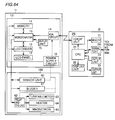
Fig. 23 is a block diagram representing configurations of the
microwave oven and the personal computer shown in Fig. 22.
Fig. 24 schematically shows the configuration of the microwave oven
system in accordance with the third embodiment of the present invention.
Fig. 25 is a block diagram representing configurations of the
microwave oven and the personal computer shown in Fig. 24.
Fig. 26 schematically shows the configuration of the microwave oven
system in accordance with the fourth embodiment of the present invention.
Fig. 27 is a block diagram representing configurations of the
microwave oven, the relay box and the personal computer of Fig. 26.
Fig. 28 shows an example of recipe information in accordance with
the fifth embodiment of the present invention.
Fig. 29 is a block diagram schematically showing the configuration
of the microwave oven system in accordance with the sixth embodiment of
the present invention.
Figs. 30A and 30B represent configurations of the recipe information
and the heating data in accordance with the sixth embodiment of the
present invention.
Fig. 31 is a flow chart representing the operation of the microwave
oven including the communication operation with the relay box, in
accordance with the sixth embodiment of the present invention.
Figs. 32 to 34 are illustrations showing examples of display images
related to the seventh embodiment of the present invention.
Fig. 35 is a flow chart representing the operations of the personal
computer and the relay box in accordance with the seventh embodiment of
the present invention.
Fig. 36 is a flow chart representing the operations of the microwave
oven and the relay box in accordance with the eighth embodiment of the
present invention.
Figs. 37A to 37C represent examples of display images displayed on
the side of the microwave oven, in accordance with the flow chart of Fig. 36.
Fig. 38 is a flow chart representing the operations of the microwave
oven and the relay box in accordance with the ninth embodiment of the
present invention.
Fig. 39 is a flow chart representing the operations of the microwave
oven and the relay box in accordance with the tenth embodiment of the
present invention.
Fig. 40 shows a configuration of the microwave oven system in
accordance with the eleventh embodiment of the present invention.
Fig. 41 is a block diagram showing configurations of respective units
of Fig. 40.
Fig. 42 is a flow chart representing operations of the microwave oven
and the relay box in accordance with the twelfth embodiment of the present
invention.
Fig. 43 shows an example of the image displayed on the side of the
microwave oven in accordance with the flow chart of Fig. 42.
Fig. 44 shows a configuration of the microwave oven system in
accordance with the thirteenth embodiment of the present invention.
Fig. 45 shows configurations of respective units of Fig. 44.
Fig. 46 is a flow chart representing operations of the personal
computer and the relay box in accordance with the thirteenth embodiment of
the present invention.
Fig. 47 is a flow chart representing operations of the microwave oven
and the relay box in accordance with the fourteenth embodiment of the
present invention.
Fig. 48 is a flow chart representing operations of the personal
computer and the relay box in accordance with the fifteenth embodiment of
the present invention.
Figs. 49A and 49B are schematic illustrations representing the
configuration of the microwave oven system in accordance with the
sixteenth embodiment of the present invention.
Fig. 50 is a block diagram showing configurations of the microwave
oven and a mobile equipment in accordance with the sixteenth embodiment
of the present invention.
Fig. 51 schematically shows functional blocks and the switching of
functions of the software in the microwave oven system in accordance with
each of the embodiments of the present invention.
Figs. 52A and 52B are flow charts representing the procedure of
accessing from the mobile equipment to the home page, in the system of Fig.
49A.
Figs. 53A to 53C represent examples of the images displayed in the
process shown in Figs. 52A and 52B.
Fig. 54 is a process flow chart of searching cooking recipe
information on the side of the host computer and loading the information to
the mobile equipment, in accordance with the sixteenth embodiment of the
present invention.
Figs. 55 to 57 represent examples of images displayed in the process
of Fig. 54.
Fig. 58 is a flow chart representing a procedure of transferring the
recipe information downloaded to the mobile equipment shown in Fig. 49 to
the microwave oven and storing the information therein.
Figs. 59 and 60 show examples of the images displayed on the mobile
equipment at the time of communication between the microwave oven and
the mobile equipment, in the process of Fig. 58.
Fig. 61 shows a state where a PHS telephone and a dedicated cable
on the side of the microwave oven are simultaneously connected to the
mobile equipment in accordance with the seventeenth embodiment of the
present invention.
Fig. 62 is a block diagram showing configurations of the microwave
oven and the mobile equipment of Fig. 61.
Figs. 63A and 63B represent the state of communication between the
mobile equipment and the microwave oven through IrDA, in accordance
with the eighteenth embodiment of the present invention.
Fig. 64 is a block diagram representing configurations of the
microwave oven and the mobile equipment of Fig. 63B.
Figs. 65A and 65B represent examples of the display images for
editing, in transferring the cooking recipe information from the mobile
equipment to the microwave oven, in accordance with the nineteenth
embodiment of the present invention.
Figs. 66A and 66B show another example of the display images for
editing in transferring the recipe information from the mobile equipment to
the microwave oven, in accordance with the nineteenth embodiment of the
present invention.
Figs. 67A and 67B represent examples of image display when the
data of a cooking recipe is to be deleted from the memory of the mobile
equipment in accordance with the twentieth embodiment of the present
invention.
Figs. 68A and 68B represent examples of images displayed for
communication standby in accordance with the twenty-first embodiment of
the present invention.
Figs. 69A and 69B represent examples of images displayed for
communication standby in accordance with the twenty-first embodiment of
the present invention.
Figs. 70A and 70B are illustrations related to an example of recipe
information downloaded to the mobile equipment and file names allotted
thereto in accordance with the twenty-second embodiment of the present
invention.
Fig. 71 is a process flow chart in accordance with the twenty-second
embodiment of the present invention.
Figs. 72A to 72D represent examples of images displayed at the
display unit of the mobile equipment in accordance with the twenty-third
embodiment of the present invention.
Figs. 73A to 73D represent examples of display images in which the
name of classified group and the corresponding registered recipe names are
displayed, in accordance with the twenty-third embodiment of the present
invention.
Fig. 74 represents correspondence between the classified groups and
the recipe names in the memory of the mobile equipment in accordance with
the twenty-third embodiment of the present invention.
Figs. 75A to 75C represent examples of display images for selecting a
recipe name to be transferred to the microwave oven, in the mobile
equipment in accordance with the twenty-fourth embodiment of the present
invention.
Figs. 76A to 76C represent examples of display images when a
desired recipe information is to be deleted from the memory of the mobile
equipment, in accordance with the twenty-fourth embodiment of the present
invention.
Figs. 77A and 77B represent examples of the display images when
the desired recipe information is deleted from the memory of the mobile
equipment in accordance with the twenty-fourth embodiment of the present
invention.
Figs. 78A and 78B represent examples of the display images for
selecting a recipe name to be transferred to the microwave oven, in the
mobile equipment in accordance with the twenty-fifth embodiment of the
present invention.
Figs. 79A to 79D represent examples of the images displayed when
a desired recipe information is to be deleted from a plurality of recipe
informations downloaded to the mobile equipment, in accordance with the
twenty-fifth embodiment of the present invention.
Fig. 80 is a schematic diagram representing a configuration of the
microwave oven system in accordance with the twenty-sixth embodiment of
the present invention.
Fig. 81 is a block diagram representing configurations of various
units of Fig. 80.
Fig. 82 shows an example of a home page screen displayed in
accordance with the home page information stored in the home page storing
unit of the host computer shown in Fig. 80.
Fig. 83 is a flow chart of the process of analyzing heating information
in accordance with the twenty-sixth embodiment of the present invention.
Fig. 84 shows the heating information stored in the memory unit in
accordance with the flow chart of Fig. 83.
Fig. 85 shows another flow chart of the process of analyzing heating
information in accordance with the twenty-sixth embodiment of the present
invention.
Figs. 86A and 86B show examples of the home page screen displayed
when the function is updated, applied to the twenty-seventh embodiment of
the present invention.
Fig. 87 is a process flow chart of data transfer for updating, at the
time of function update, applied to the twenty-seventh embodiment of the
present invention.
Fig. 88 is a flow chart of the process of updating function in the relay
box of Fig. 87.
Fig. 89 is a flow chart of the process of updating function in the
microwave oven of Fig. 87.
Fig. 90 is a schematic diagram representing a configuration of the
microwave oven system in accordance with the twenty-eighth embodiment of
the present invention.
Fig. 91 is a block diagram representing configurations of respective
portions of Fig. 90.
Fig. 92 is a flow chart schematically representing the operation of
the relay box of Fig. 90.
Fig. 93 is a flow chart schematically representing the operation of
the microwave oven of Fig. 90.
Fig. 94 shows an example of contents stored in a flash memory on
the side of the relay box, in accordance with the flow chart of Fig. 90.
Fig. 95 represents an example of image outputs of the how-to-cook
data in the microwave oven 1J.
Fig. 96 is a flow chart of the audio output process of the how-to-cook
data in accordance with the twenty-eighth embodiment of the present
invention.
Figs. 97A and 97B represent examples of images displayed on the
microwave oven, in accordance with the process flow chart of Fig. 96.
Fig. 98 represents information stored in the memory of the
microwave oven in accordance with the twenty-ninth embodiment of the
present invention.
Fig. 99 is a process flow chart of receiving and outputting by a
personal computer, information registered on the side of the microwave oven
in association with the use of the microwave oven, in accordance with the
twenty-ninth embodiment of the present invention.
Fig. 100 is a process flow chart for the recipe registering operation in
accordance with the thirtieth embodiment of the present invention.
Fig. 101 represents a procedure for executing the heating and
cooking operation in the microwave oven, based on the data prepared in
accordance with the flow chart of Fig. 100.
Fig. 102 is a schematic diagram representing a configuration of the
microwave oven system applied to the thirty-first embodiment of the present
invention.
Fig. 103 is a process flow chart showing a series of processes for
heating and cooking a frozen food in accordance with the thirty-first
embodiment of the present invention.
Fig. 104 shows a system configuration for registering and supplying
recipe information in accordance with the thirty-second embodiment of the
present invention.
Fig. 105 shows a configuration of a personal computer 50A installed
in a shop 50i of Fig. 104.
Figs. 106 to 112 show examples of home page images displayed in
accordance with the home page information stored in home page storing unit
421A of host computer 4K shown in Fig. 104.
Fig. 113 is a flow chart representing the procedure of registering
recipe information MI by the shop 50i.
Fig. 114 is a process flow chart for supplying the recipe information
MI registered in accordance with the procedure of Fig. 113 to the user.
Fig. 115 shows a process flow chart when an order for an item is
placed with shop 50i, by the click of a button 807 of Fig. 111.
Figs. 116A and 116B represent schematic configuration of the
microwave oven system in accordance with the thirty-third embodiment of
the present invention.
Figs. 117A and 117B represent block configurations of the
microwave oven and the mobile equipment.
Figs. 118A to 118C show the manner of connecting a mobile
equipment 2J to microwave oven 1J.
Fig. 119 is a schematic diagram of a connector unit of an I/F unit 26J
of mobile equipment 2J shown in Figs. 116A and 116B.
Fig. 120 is a circuit diagram of a portion inside microwave oven 1J,
related to the communication with mobile equipment 2J, shown in Fig.
117B.
Fig. 121 shows a state of connection where the microwave oven and
the mobile equipment are connected by a dedicated cable in accordance with
a thirty-fourth embodiment of the present invention.
Fig. 122 shows an appearance of the dedicated cable shown in Fig.
121.
Fig. 123 shows a connector unit provided on the microwave oven of
Fig. 121.
Fig. 124 shows an appearance of the connector unit provided on the
mobile equipment shown in Fig. 121.
Fig. 125 shows a circuit in a connector unit in accordance with the
thirty-fourth embodiment of the present invention.
DESCRIPTION OF THE PREFERRED EMBODIMENTS
Embodiments of the present invention will be described in the
following. The microwave oven in accordance with each of the
embodiments is capable of heating and cooking a plurality of different
cooking recipes, in accordance with a plurality of different pieces of heating
information stored as standard specification. In addition to such a function,
the microwave oven has a function of heating and cooking a desired cooking
recipe in accordance with the heating information of the desired cooking
recipe received through the Internet.
First Embodiment
Fig. 1 is a schematic diagram showing a configuration of the
microwave oven system in accordance with the first embodiment of the
present invention.
Fig. 2 is a block diagram showing configurations of respective units
of Fig. 1.
Referring to Fig. 1, the microwave oven system includes, in public,
the Internet 5 and a host computer 4 connected thereto, and in private, a
microwave oven 1, a personal computer 2 connected through a modem 6 to
the Internet 5, and a relay box 3 fed from an AC adapter 8, as a relay
apparatus for connecting personal computer 2 and microwave oven 1,
converting and communicating signals therebetween. In private,
microwave oven 1 and relay box 3 are connected by a three-line cable 9. For
this connection, a connector CN at one end of the three-line cable 9 is
connected to an input/output terminal, not shown, of microwave oven 1. In
private, personal computer 2 and relay box 3 are connected by an RS-232C
cable 7 for communication in accordance with RS-232C.
In the public host computer 4, information related to various home
pages to be accessed through the Internet 5 are registered. Host computer
4 includes a processing unit 41 for centralized control and management of
host computer 4 itself, a memory 42 having a home page storing unit 421 as
a memory area storing information including information for constructing
home page screen (hereinafter referred to as home page information), an
input unit 43, an output unit 44, and a communication unit 45 for
communication and connection between the Internet 5 and host computer 4.
Referring to Fig. 2, microwave oven 1 includes a control unit 10A and
a heating unit 10B. Control unit 10A includes a microcomputer 10, a
memory 11, an LCD (Liquid Crystal Display) panel 13 as a display unit, an
LCD driver 12 for driving LCD panel 13, an I/F (Interface) unit 14 including
an input/output terminal to which a connector CN is connected, an
externally operable input unit 15, and a power supply circuit 16 for
supplying power to respective units of microwave oven 1. Input unit 15 and
LCD panel 13 are provided integrally, as a touch panel.
Heating unit 10B performs the heating operation for heating and
cooking in accordance with various pieces of information including the
heating data, which will be described later, stored in memory 11, under the
control of microcomputer 10. For the heating operation, heating unit 10B
includes a sensor unit 60, a buzzer 61, a relay or the like 62, a turntable
motor 63 controlled by microcomputer 10 through relay or the like 62, a
heater 64 and a magnetron 65 generating microwaves for heating. The
heating operation by the heating unit 10B is in accordance with the known
technique, and therefore detailed description will not be given here. In
memory 11, heating data related to at least one cooking recipe provided as a
standard specification of microwave oven 1 is stored.
Personal computer 2 includes a CPU 20, a memory 21 storing
information including a dedicated program PRO, which will be described
later, a display unit 22, an output unit 23, an externally operable input unit
24, an RS-232C port 25 for connecting RS-232C cable 7 with the CPU 20,
and an I/F unit 26 for connecting modem 6 with CPU 20.
Relay box 3 includes a microcomputer 30, a flash memory 31 as a
nonvolatile storing element, a transmitting/receiving unit 32 for connecting
RS-232C cable 7 with the microcomputer 30, an I/F unit 33 for connecting
the three-line cable 9 with the microcomputer 30, and a power supply circuit
34 for feeding power to respective units.
For the communication through the three-line cable 9, UART
(Universal Asynchronous Receiver Transmitter) is adopted.
The procedure of cooking by a private microwave oven 1 using
cooking information publicly available through the Internet 5 in the host
computer 4 as a home page server will be described in the following.
Figs. 3, 4 and 5 represent examples of home page screen images in
Japanese, displayed in accordance with the home page information stored in
the home page storing unit 421 of host computer 4 of Fig. 1. Figs. 3, 4 and 5
represent examples of home page screen images provided by the applicant
on the Internet. When a user operates personal computer 2 and accesses a
prescribed address corresponding to the host computer 4 through the
Internet 5, the home page display of Fig. 3 appears on the output unit 23 of
personal computer 2. When the user clicks, by the input unit 24, the item
"microwave oven" indicated by an arrow A on the home page screen, the
home page screen of Fig. 4 appears. The home page screen of Fig. 4
provides daily menu of June, in the form of a calendar. Here, a home page
screen having the title of "menu calendar of June" is shown as an example.
By designating the preceding or succeeding screen images, the user can
browse monthly menu calendar of one year, for example, on the home page.
For simplicity of description, only the portions denoted by the arrow are
translated into English in Figs. 3 to 5.
When the user designates a cooking recipe represented by the arrow
A on the home page screen of Fig. 4, the home page screen of Fig. 5 appears,
showing a video image of the finished cooking recipe, information of
materials and information of how-to-cook. Though only an example of the
home page screen is shown in Fig. 5, home page information of the home
page screen image of Fig. 4 described above for each recipe of one year, as
presented on the home page screen of Fig. 4, are prepared in advance in the
home page storing unit 421.
When the user designates and clicks the item "download of cooking
data" denoted by the arrow A on the home page screen of Fig. 5, the data to
be displayed to the user through the microwave oven 1 and the heating data
used for heating and cooking by the heating unit 10B of the microwave oven
1 related to the cooking recipe shown in Fig. 5 are down-loaded from host
computer 4 through the Internet 5 to the personal computer 2, in response.
It is noted that a dedicated program PRO to enable the function
corresponding to the click of the item denoted by the arrow A is installed in
advance in memory 21 of personal computer 2.
Fig. 6 is a schematic flow chart of the procedure for preparing recipe
information of cooking recipe when the home page is prepared or authored,
in accordance with the present embodiment.
Fig. 7 is a schematic diagram representing the material data
prepared successively in accordance with the procedure of preparing recipe
information of Fig. 6. The material data is prepared successively along the
direction of the arrows.
Fig. 8 schematically shows the how-to-cook data prepared
successively in accordance with the procedure for preparing recipe
information of Fig. 6. The how-to-cook data is prepared successively in the
direction of the arrows.
The presenter of the home page prepares home page information
corresponding to the home page screens of Figs. 3 to 5 by using a prescribed
program in host computer 4, converts the format of the information, as will
be described later, and stores the information in home page storing unit 421.
As the technique is well known, detailed description is not given here.
The menu information is prepared for each cooking recipe in
accordance with the procedure of Fig. 6. Here, description will be given on
a cooking recipe "Tofu-based hamburger" denoted by the arrow A in Fig. 4,
as an example.
First, the presenter of the home page prepares display data by
operating input unit 43 of host computer 4, converts the format as will be
described later, and stores the data in home page storing unit 421 (T1 of Fig.
6). More specifically, the presenter of the home page prepares material
data IDi representing materials as shown in Fig. 7 for each cooking recipe,
thereafter prepares the how-to-cook data JDi representing the manner of
cooking of Fig. 8, converts the data format, and stores in the home page
storing unit 421.
Thereafter, the heating data KDi representing data related to
control of the heating operation of microwave oven 1 for heating and cooking
the cooking recipe is prepared, the format is converted and stored in home
page storing unit 421 (T2 of Fig. 6). The prepared data are stored in home
page storing unit 421, recipe by recipe of cooking.
The heating data KDi of Fig. 9 are respectively prepared
successively in the direction of the arrow, in correspondence to items H1 to
H3, "start heating" of Fig. 8. Each heating data KDi consists of mode data
D1 representing operation mode (microwave oven mode or oven mode) of
microwave oven 1, output level data D2 representing an output level
(unit:W) of the microwave oven 1 in the operation mode represented by mode
data D1, a temperature data D3 representing the set temperature of heating
(unit: °C), and a time data D4 (unit: minutes and seconds) representing the
time necessary for heating.
Fig. 10 represents home page information including the recipe
information of each recipe prepared in accordance with the procedure of Fig.
6. The home page information HMD shown in the figure corresponds to the
home page screen of Fig. 5, and includes image display data DS15 to be
displayed on the home page screen to form the home page screen image,
display data DS13 to be displayed on microwave oven 1, and recipe
information consisting of heating data DS14 for controlling the heating
operation of microwave oven 1.
Image display data DS15 is the data to provide the image to be
displayed to the user on the home page screen of Fig. 5, and the item
"download of cooking data" denoted by the arrow A corresponds to a transfer
button B1 of data DS15 of Fig. 10.
Therefore, when the item "download of cooking data" denoted by the
arrow A of Fig. 5 is denoted and clicked by the user, transfer button B1 of
Fig. 10 is clicked, and the processing unit 41 of host computer 4 down-loads
recipe information MI including the corresponding display data DS13 and
heating data DS14 to the personal computer 2 through communication unit
45 and the Internet 5.
The recipe information MI shown in Fig. 10 is a so-called hidden
information not visible (not displayed) on the home page screen displayed on
the display unit 22 of personal computer 2, which information includes
recipe name MN of the corresponding cooking recipe, and the material data
IDi and the how-to-cook data JDi prepared in accordance with the
procedures of Figs. 7 to 9.
Fig. 11 is a data list obtained by format-conversion of recipe
information MI shown in Fig. 10.
In the processes T1 and T2 of Fig. 6, display data DS13 and heating
data DS14 of Fig. 10 are stored in home page storing unit 421 after
converted to such data format that can be recognizable by microcomputer 10
of microwave oven 1, in the manner as shown in Fig. 11 by the processing
unit 41 of host computer 4.
When the data of Fig. 11 is to be down-loaded to personal computer 2
through the Internet 5, the data is further converted to specific codes by
processing unit 41. When the home page information HMD is accessed
through the Internet 5 (T3 of Fig. 6), processing unit 41 determines whether
there is a download request by a click of transfer button B1 (T4 of Fig. 6),
and when the button is clicked, recipe information MI corresponding to the
accessed home page information HMD is down-loaded to personal computer
2 (T5).
Fig. 12 is a flow chart summarizing the operation related to
downloading of the recipe information by the personal computer 2 of Fig. 1.
Referring to the figure, the private user accesses host computer 4 of the
home page through the Internet 5 by operating an input unit 24 of personal
computer 2 (F1 of Fig. 12), so that the data for the home page screen
including image display data DS15 of the home page information HMD in
the home page storing unit 421 of host computer 4 are transmitted to
personal computer 2, and the home page image display of Fig. 3 is displayed
on output unit 23 (F2). When the item "microwave oven" represented by
the arrow A on the home page screen of Fig. 3 is clicked by input unit 24, the
screen image is switched to the home page screen image of Fig. 4 showing
the monthly menu (F3, F4).
When "Tofu-based hamburger" denoted by the arrow A is clicked by
input unit 24 on the home page screen of Fig. 4, the screen image is switched
to the cooking recipe image display of "Tofu-based hamburger" of Fig. 5 (F5
and F6).
When the item "download of cooking data" designated by the arrow A
of Fig. 5 is clicked by the user at input unit 24, the recipe information MI
including corresponding display data and heating data DS13 and DS14 of
Fig. 11 in home page storing unit 421 of host computer 4 is transmitted to
personal computer 2, and temporarily stored in memory 21 (F8, F9).
A button to be operated to designate "download of cooking data" is
provided on each menu screen, so as to enable transmission of the cooking
information MI including display data DS13 and heating data DS14 to
personal computer 2.
The function corresponding to the operation of transfer button B1 on
the home page screen becomes effective when a dedicated program PRO is
installed to memory 21 of personal computer 2 from a flexible disk appended
to the purchased relay box 3. The dedicated program PRO automatically
designates the recipe information MI to be down-loaded and automatically
designates the destination of storage of the downloaded recipe information
MI, so that by a simple click of transfer button B1, the function of
downloading recipe information M1 and the function of transmitting recipe
information MI temporarily stored in personal computer 2 to relay box 3 are
attained.
As to the method of installing the dedicated program PRO to the
memory 21, the following methods are popular and preferred. Namely, the
program may be installed by inserting a flexible disk appended to the relay
box 3 to a flexible disk driver, or the control program PRO may be presented
on a home page, so that the user inputs an identification number (ID)
allotted to the purchaser of relay box 3 through input unit 24, and the
program is down-loaded and installed in personal computer 2.
General method of communication must be established between
personal computer 2 and microwave oven 1. Therefore, in the present
embodiment, RS232-C standard, establish for stable bi-directional
communication, is adopted.
Fig. 13 is a flow chart schematically showing the operation of relay
box 3.
When there is a download request of recipe information MI
generated by personal computer 2 in the above described manner, a
communication request is transmitted from personal computer 2 to relay box
3, the recipe information MI including display data and heating data DS13
and DS14 are transmitted in accordance with RS-232C standard, and the
information is stored in flash memory 31 through transmitting/receiving
unit 32 and microcomputer 30 (F10 to F12 of Fig. 13). Thereafter,
microcomputer 30 transmits a notification of recipe information storage
complete, notifying completion of storage of the recipe information, to the
microwave oven 1 (F121).
It is possible to store recipe information MI of a plurality of cooking
recipes in flash memory 31.
Upon request of microcomputer 10 of microwave oven 1,
microcomputer 30 of relay box 3 transmits all the recipe names MN stored in
flash memory 31 to microcomputer 10 of microwave oven 1 through a cable 9
(F13 and F14).
Thereafter, in accordance with an instruction from microcomputer
10 of microwave oven 1, microcomputer 30 in relay box 3 transmits, among
at least one recipe information MI stored in flash memory 31, the display
data and heating data DS13 and DS14 corresponding to the designated
recipe name MN to microcomputer 10 of microwave oven 1 (F16).
Fig. 14 is a flow chart schematically showing the operation of the
microwave oven shown in Fig. 1. Figs. 15A to 15D are illustrations of the
images displayed on the microwave oven, in the flow chart of Fig. 14. Fig.
16 represents an example of contents stored in flash memory 31 of the relay
box of the flow chart of Fig. 14.
Figs. 15A to 15D represent examples of display images of a touch
panel which is an integration of input unit 15 and LCD panel 13 of Fig. 2.
An internet key 174 shown in Fig. 15B of microwave oven 1 is operated to
receive and display the recipe information MI from the host computer 4 of
the home page through the Internet 5, personal computer 1 and relay box 3.
Fig. 15D shows a recipe name display area 175, a material display area 176
and a how-to-cook display area 177 displaying the received recipe name MN,
material data IDi and the how-to-cook data JDi, in addition to a start key
173 to be operated to start heating and cooking by microwave oven 1 in
accordance with the received heating data KDi.
It is possible to store at most five pieces of recipe information MI, for
example, in flash memory 31. In Fig. 16, five pieces of recipe information
MI received from the host computer 4 of the home page through the Internet
5 and personal computer 2 are stored in advance in the example of Fig. 16.
Each recipe information MI includes recipe name MNi (i: 1, 2, 3 ...), material
data IDi, how-to-cook data JDi and heating data KDi.
The operation of microwave oven 1 shown in Fig. 14 will be described
with reference to Figs. 15A to 15D and Fig. 16. It is assumed that the
contents of Fig. 16 are already stored in flash memory 31 of relay box 3. Fig.
15A shows the display when the power of microwave oven 1 is turned on.
Figs. 15B to 15D show displays given after power on until starting heating
and cooking of the desired cooking recipe using the information received
through the Internet 5.
First, a power switch, not shown, related to power supply circuit 16
of microwave oven 1 is turned on by the user, so that power is supplied to
microwave oven 1, and the display of Fig. 15A is given on LCD panel 13
(F161). When turned on, microwave oven 1 is ready to heat and cook a
plurality of cooking recipes set in advance as standard specification, in
advance. Here, as can be seen from the figure, cooking recipes such as
cookies, cakes, butter rolls and the like are stored as standard setting.
These cooking recipes can be heated and cooked by heating unit 10B in
accordance with the information for heating and cooking, set in advance in
microwave oven 1.
When the user desires to heat and cook using information received
through the Internet 5, the user connects the connector CN shown in Fig. 1
to an input/output terminal, not shown, of microwave oven 1, whereby relay
box 3 is connected to microwave oven 1. At this time, as one or more recipe
information MI such as shown in Fig. 16 is stored in flash memory 31 as
described above, the notification of recipe information storage complete is
transmitted from microcomputer 30 of relay box 3 to microcomputer 10 of
microwave oven 1 through cable 9. When the notification of recipe
information storage complete is received by microcomputer 10, the manner
of display is changed as shown in Fig. 15B, with the internet key 174
highlighted, for example. It is possible for the user to know that the recipe
information MI has already been stored in flash memory 31 of relay box 3, by
the change in the manner of display of internet key 174 (F163).
Confirming the manner of display of internet key 174 of Fig. 15B
representing that the recipe information MI has already been stored in flash
memory 31 of relay box 3, the user operates internet key 174, and
microcomputer 10 request all the recipe names MN to microcomputer 30 of
relay box 3 through the cable 9 (F17, F18).
In response to the request of all recipe names MN, microcomputer 30
reads all the recipe names MNi from flash memory 31 of Fig. 16, and
transmits the recipe names to microwave oven 1 through the cable 9.
Therefore, microcomputer 10 of microwave oven 1 receives all the recipe
names MNi, and displays the names on LCD panel 13 as shown in Fig. 15C
(F19 to F20).
Among the all recipe names MNi displayed as shown in Fig. 15C,
when the recipe "Chinese steamed rice" denoted by the arrow A, for example,
is operated (touched) and designated by the user, microcomputer 10 request
display data DS13 and heating data DS14 of the designated recipe name
MN3 ("Chinese steamed rice") to relay box 3 through cable 9 (F21 and F22).
In response to the request of data corresponding to recipe name MN3
("Chinese steamed rice") from microwave oven 1, microcomputer 30 of relay
box 3 reads and transmits display data DS13 (recipe name MN3, material
data ID3 and how-to-cook data JD3) and heating data KD3 corresponding to
the recipe name MN3 ("Chinese steamed rice") from flash memory 31, so
that microcomputer 10 of microwave oven 1 receives the display data DS13
and heating data KD3 and temporarily writes and stores in memory 11 (F22
and F23).
Microcomputer 10 provides the display of Fig. 15D on LCD panel 13
so as to urge the instruction input of the user to start heating and cooking of
the designated recipe (F24). When start key 173 of Fig. 15D is operated,
heating and cooking by heating unit 10B starts, in accordance with the
heating data KDi. As shown in Fig. 15D, recipe name MN3, material data
ID3 and how-to-cook data JD3 of the received display data DS13 are
displayed in recipe name display area 175, material display area 176 and
how-to-cook display area 177, respectively.
Fig. 17 is an illustration showing, in time-sequential manner in the
direction of the arrows, how the displays related to Fig. 15D are given.
When the material data IDi and the how-to-cook data JDi to be displayed in
the material display area 176 and the how-to-cook display area 177 of Fig.
15D contain too large an amount of data to be fully displayed on areas 176
and 177, display on LCD display 13 is updated as shown in Fig. 17, every
time the user operates (touches) the display area 176 or 177, so that the
large amount of material data IDi and the how-to-cook data JDi are divided
and displayed successively. As the material data IDi and the how-to-cook
data JDi are displayed in a plurality of display images as shown in Fig. 17, it
becomes possible for the user to prepare and arrange the materials while
updating the display.
Figs. 18A to 18C represent examples of the display images on the
microwave oven 1, when the recipe information is not stored in flash
memory 31 of relay box 3 in accordance with the first embodiment of the
present invention.
In the operation of microwave oven 1 in accordance with the flow
chart of Fig. 14, it is assumed that one or more recipe information MI is
stored in advance in flash memory 31 of relay box 3. When microwave oven
1 is turned on and the connector CN of Fig. 1 is connected to the
input/output terminal, not shown, of microwave oven 1 with the recipe
information MI not stored in flash memory 31, the notification of recipe
information storage complete is not transmitted from relay box 3, and
therefore, following the display of Fig. 18A given at the time of power on, the
display of Fig. 18B appears on LCD panel 13.
In the display of Fig. 18B, the manner of display of internet key 174
is not highlighted, and hence it is notified that recipe information MI is not
at all stored in flash memory 31 of relay box 3.
When the user operates internet key 174, the display of Fig. 18C
appears on LCD panel 13, giving a message to the user that the recipe
information MI is not at all stored in flash memory 31 of relay box 3, and
that a cooking recipe is to be selected from the home page. Confirming the
message, the user performs the operation of Fig. 12 described above.
Accordingly, processes of the flow charts of Figs. 13 and 14 take place,
whereby heating and cooking of the desired recipe starts by the microwave
oven 1 in accordance with the heating data KDi.
Fig. 19 is a flow chart representing a procedure for replacing the
recipe information stored in the memory of relay box 3 with other recipe
information, by an instruction input from the microwave oven 1 in
accordance with the first embodiment of the present invention.
Figs. 20A to 20C represent changes in the contents of the memory in
relay box 3, in accordance with the flow chart of Fig. 19.
Figs. 21A to 21F represent changes in the display images of the
microwave oven 1, in accordance with the flow chart of Fig. 19. Referring to
Figs. 21A to 21F, the images to be displayed are switched successively, in the
direction represented by the dotted arrows.
In accordance with the flow chart of Fig. 19, the procedure of
replacing the recipe information stored in flash memory 31 of relay box 3
with other recipe information will be described, with reference to Figs. 20A
to 20C and 21A to 21F.
It is assumed that five pieces of recipe information MI have been
already stored in flash memory 31, as shown in Fig. 20A.
First, the user operates microwave oven 1 as described with
reference to Fig. 14, and hence the images of Figs. 21A to 21C are
successively switched and displayed based on the data received from relay
box 3, on LCD panel 13 of the microwave oven 1 (F161 to F24 and F30 to F32
of Fig. 19).
The display of Fig. 21C includes a delete key 178. When the delete
key 178 is operated by the user on the display of Fig. 21C (F25), the display
of Fig. 21D appears, giving a message asking whether the recipe information
MI of flash memory 31 corresponding to the recipe name MN3 ("Chinese
steamed rice") displayed on recipe name display area 175 is to be deleted or
not. When delete key 179 is pressed, the display of Fig. 21E appears (F26).
The display of Fig. 21E corresponds to the image display when the recipe
name MN3 ("Chinese steamed rice") is deleted in the display of Fig. 21B.
Thereafter, microcomputer 10 of microwave oven 1 issues a request
for deleting recipe information MI corresponding to the recipe name MN3
("Chinese steamed rice") to microcomputer 30 of relay box 3 through cable 9.
In response to reception of the deletion request of recipe information,
microcomputer 30 deletes the corresponding recipe information MI in the
flash memory 31 (F27, F33).
Thus, the contents of flash memory 31 are changed from those of Fig.
20A to 20B.
Thereafter, the user operates the input unit 24 of personal computer
2, designates a new cooking recipe, for example a cooking recipe of which
recipe name MN is "potato salad" from the home page (F36) in accordance
with the procedure shown in Fig. 12, CPU 20 receives the recipe information
MI corresponding to the new recipe from the host computer 4 of the home
page through the Internet 5, and stores temporarily in memory 21 (F37).
Thereafter, the received recipe information MI is transmitted to relay box 3
through RS-232C cable 7 (F38).
Microcomputer 30 of relay box 3 receives the new recipe information
MI corresponding to the recipe name MN ("potato salad") transmitted from
personal compute 2, and stores in a free area of Fig. 20B. Thus the contents
of flash memory 31 is changed from that of Fig. 20B to 20C. In order to
specify the newly stored recipe information MI in flash memory 31,
microcomputer 30 uses a pointer PNT to designate the recipe information
MI.
Next, when microwave oven 1 is operated by the user, the internet
key 174 of Fig. 21A is operated (F28). As the microcomputer 10 recognizes
that recipe information MI has been deleted by delete keys 178 and 179,
microcomputer 10 request the new recipe name to relay box 3 through cable
9, in response to the operation of internet key 174 (F29). In response to the
request, microcomputer 30 of relay box 3 reads the recipe name MN3
("potato salad") of recipe information MI denoted by the pointer PNT of flash
memory 31, and transmits to microcomputer 10 of the microwave oven 1.
Microcomputer 10 of microwave oven 1 receives recipe name MN3
("potato salad"), temporarily stores in memory 11, and display all the recipe
names MNi including the new recipe name MN3, as shown in Fig. 21F (F29).
In the first embodiment, in order to urge the user to download latest
information from the home page constantly, the recipe information MI which
can be stored in the flash memory 31 of relay box 3 is set to five at most.
The number of pieces of recipe information, however, is not limited to 5.
In this manner, when the cooking recipe introduced on the home
page of host computer 4 is to be heated and cooked by heating unit 10B of
the private microwave oven 1, the operation of setting various data related
to microwave oven 1 for heating and cooking is unnecessary, which is
convenient for the user.
Second Embodiment
Second embodiment will be described in the following. Fig. 22 is a
schematic diagram representing a configuration of a microwave oven system
in accordance with the second embodiment of the present invention. Fig.
23 is a block diagram showing configurations of microwave oven 1A and
personal computer 2A. In Fig. 22, microwave oven 1A and personal
computer 2A have infrared emitting/receiving units 66 and 27 for wireless
communication by IrDA (Infrared Data Association) therebetween. When
microwave oven 1A and personal computer 2A of Fig. 23 are compared with
microwave oven 1 and personal computer 2 of Fig. 2, respectively, there are
the following differences. Namely, microwave oven 1A is provided with an
IrDAI/F unit 141 related to the infrared emitting/receiving unit 66 in place
of I/F unit 14 of Fig. 2, and personal computer 2A is provided with an
IrDAI/F unit 251 related to an infrared emitting/receiving unit 27 in place of
RS-232C port 25 of Fig. 2. Other structures of microwave oven 1A and
personal computer 2A are the same as those of Fig. 2, and hence description
thereof is not repeated here.
In the first embodiment described above, connection and
communication between microwave oven 1 and personal computer 2 were
established by cable, with relay box 3 interposed. In the second
embodiment, wireless communication using an infrared ray, for example,
using IrDA, is adopted in place of communication using cables, as shown in
Figs. 22 and 23. Therefore, the troublesome wiring of cables for the
microwave oven system becomes unnecessary, which facilitates installation
of the system.
Third Embodiment
A third embodiment will be described in the following. Fig. 24 is a
schematic diagram representing the microwave oven system in accordance
with the third embodiment of the present invention. Fig. 25 represents
block configurations of microwave oven 1B and personal computer 2B of Fig.
24.
In Fig. 24, microwave oven 1B and personal computer 2B are
provided with RAM card inlets 67 and 28, which are card slot interfaces to
which an RAM card 80 is inserted, for transferring data therebetween by
using a card shaped RAM (Random Access Memory) card 80.
When microwave oven 1B and personal computer 2B are compared
with microwave oven 1 and personal computer 2 of Fig. 2, there are the
following differences. More specifically, microwave oven 1B is provided
with an RAM card I/F unit 142 for accessing the data of RAM card 80
inserted through RAM card inlet 67, in place of I/F unit 14 of Fig. 2, and that
personal computer 2B is provided with an RAM card I/F unit 252 for
accessing the data of RAM card 80 inserted through RAM card inlet 28
under the control of microcomputer 30, in place of RS-232C port 25 of Fig. 2.
Other structures of microwave oven 1B and personal computer 2B are the
same as those shown in Fig. 2, and therefore description is not repeated.
In the above described first embodiment, microwave oven 1 and
personal computer 2 are communicated and connected by a cable through a
relay box 3. In the present embodiment 3, data transfer is performed using
an RAM card 80 in place of the cable communication, as can be seen from
Figs. 24 and 25, so that the relay box 3 can be omitted, the trouble of cable
wiring for the electronic oven system can be avoided and the system can be
readily provided.
Fourth Embodiment
The fourth embodiment will be described in the following. Fig. 26 is
a schematic diagram of the microwave oven system in accordance with the
fourth embodiment of the present invention. Fig. 27 shows block
configurations of microwave oven 1, relay box 3C and personal computer 2C.
In the system of Fig. 26, a cable 7C is provided in place of RS232C
cable 7 of the system of Fig. 1. Cable 7C is to provide an interface for the
communication and connection between relay box 3C and personal computer
2C, and USB (Universal Serial Bus) or parallel interface is adopted. Other
structures of the system shown in Fig. 26 are the same as those of Fig. 1.
In Fig. 27, relay box 3C has an I/F unit 32C in place of the
transmitting/receiving unit 32 of Fig. 2, and personal computer 2C has an
I/F unit 25C in place of RS232C port 25. Other structures of relay box 3C
and personal computer 2C are the same as those of Fig. 2.
I/F unit 32C and I/F unit 25C connect and communicate between
cable 7C and microcomputer 30 and cable 7C and CPU 20, in accordance
with the USB interface or parallel interface method corresponding to the
interface applied to cable 7C.
In the fourth embodiment, data transfer takes place in accordance
with USB or parallel interface between relay box 3C and personal computer
2C, and therefore, compared with data transfer in accordance with RS-232C
of the first embodiment, data can be transferred at a higher speed.
Further, when other equipment, not shown, is connected through a
cable 7 to RS-232C port 25 of personal computer 2C and RS-232C port 25 is
not available as shown in Fig. 27, the system configuration of the fourth
embodiment is very effective.
Fifth Embodiment
The fifth embodiment will be described in the following.
In the fifth embodiment, a data configuration of recipe information
MI is described, which can reduce time of transmission of recipe name MNi
from relay box 3 to microwave oven 1 of Fig. 1 and which can reduce memory
capacity necessary for storing the recipe name MNi received by microwave
oven 1. The configuration of microwave oven system and configuration of
each unit of the fifth embodiment are the same as those shown in Figs. 1 and
2, and therefore description is not repeated.
Fig. 28 shows an example of configuration of recipe information MI
in accordance with the fifth embodiment. Referring to Fig. 28, recipe
information MI includes a plurality of addresses AD, data contents DC
representing contents of data stored in the area represented by the
corresponding address AD, and capacity CA of data contents DC. The
capacity CA represents the maximum value.
Recipe information MI includes data DC1 including a data code, a
final address and an extension code; and head address DC2 of an area where
heating data KDi and recipe name MNi are stored; head/last address DC3 of
image display page address information; recipe name MNi, heating data
KDi; image display page address information DC4; and display data DS13
including material data IDi and how-to-cook data JDi, as represented by
data contents DC of Fig. 28.
As shown in the figure, in recipe information MI, the first 23 bytes
from the head are configured including fixed length data DC1 to DC3, and
the data following recipe name MNi are variable length data. Though
recipe information MI may have different capacity dependent on the cooking
recipe, here, each recipe information MI has the maximum capacity of 2048
bytes.
As described with reference to the first embodiment, when internet
key 174 is operated, only the recipe name MNi (32 bytes) is read from recipe
information MI shown in Fig. 28 of flash memory 31 of relay box 3 and
transmitted to microwave oven 1, and therefore, as compared with
transmission of the whole recipe information MI (2048 bytes) per one recipe,
the time necessary for data transmission and necessary memory capacity of
microwave oven 1 can be reduced to 1/64.
Sixth Embodiment
The sixth embodiment will be described. Fig. 29 schematically
shows the configuration of the microwave oven system in accordance with
the sixth embodiment of the present invention. In Fig. 29, a microwave
oven 1D is provided in place of microwave oven 1 of Fig. 2. Other
structures of Fig. 29 are the same as those of Fig. 2, and hence description is
not repeated.
Microwave oven 1D of Fig. 29 includes a control unit 11D. Control
unit 11D includes a memory 111 in place of memory 11 of control unit 10A of
Fig. 2. A machine type code specifying the machine type of microwave oven
1D is stored in advance in memory 111.
Figs. 30A and 30B represent configurations of the recipe information
and the heating data in accordance with the sixth embodiment of the
present invention. Fig. 31 is a flow chart representing the operation of
microwave oven 1D, including communication with relay box 3, in
accordance with the sixth embodiment.
The recipe information MI1 of Fig. 30A includes data DC11 and
heating data KD1i, in place of data DC1 and heating data KDi of recipe
information MI shown in Fig. 28. Other contents of recipe information MI1
are the same as those of Fig. 28.
Data DC11 includes, in place of the extension code of data DC1, a
machine type code for specifying the machine type of the microwave oven
which can operate in accordance with recipe information MI1, applicable to
the microwave oven system in accordance with the present embodiment.
Fig. 30B shows the configuration of heating data KD1i. The
performance of heating unit 10B of microwave oven 1D differs dependent on
the machine type of microwave oven 1D, as the maximum output of
microwaves from magnetron 65 or operation of heater 64 differs. Therefore,
unless the heating data KD1i optimized for the machine type is used, the
finish of cooking will not be satisfactory, or the time of cooking will be longer.
Therefore, in the sixth embodiment, using the machine type code MD,
whether the heating data KD1i received by microcomputer 10 of microwave
oven 1D is suitable for use or not is determined.
The heating data KD1i includes a plurality of different machine type
codes MD1 applicable to the microwave oven system, and data DD for
controlling the heating operation of heating unit 10B corresponding to each
machine type code MD1.
Microwave oven 1D will be described with reference to the flow chart
of Fig. 31. Here, it is assumed that the machine type code MD of microwave
oven 1D is "01".
When the internet key 174 is operated on the side of microwave oven
1D (T12), a data representing key input is transmitted from microcomputer
10 to microcomputer 30 of relay box 3 (T13). Upon reception of the data
(T14, T141), microcomputer 30 of relay box 3 reads recipe name MNi from
recipe information MI1 of flash memory 31 (T15) and transmits the read
recipe name to microcomputer 10 (T16). Microcomputer 10, receiving the
data, display all the received recipe names MNi (T17, T171, T18). Assume
that a plurality of recipe names MNi have been transferred and displayed.
When the user selects one of the plurality of displayed recipe names
MNi, for example, "shrimp salad" (T19), microcomputer 10 transmits the key
input (T20). Microcomputer 30 of relay box 3 receives the information (T21,
T211), and reads and transmits the heating data and the display data KD1i
and DS13 corresponding to the recipe name MNi "shrimp salad" from recipe
information MI1 (T22, T23).
Microcomputer 10 of microwave oven 1D receives the data
transmitted from microcomputer 30 (T24, T241), and searches the heating
data corresponding to the machine type code MD ("01") of microwave oven
1D, among the received heating data KD1i (T25). If there is no heating
data DD corresponding to the machine type code MD ("01"), a display is
given, notifying that heating and cooking by microwave oven 1D is not
possible (T26). When there is the corresponding heating data DD, the
heating data DD is set in the control unit 11D of microwave oven 1D, as the
data for controlling the heating operation of heating unit 10B.
Therefore, the heating and cooking operation using the heating data
optimized for the machine type of microwave oven 1D is possible.
Seventh Embodiment
The seventh embodiment will be described in the following.
Figs. 32 to 34 are examples of image displays related to the seventh
embodiment of the present invention. Fig. 35 is a flow chart related to the
operation of relay box 3 and personal computer 2 in accordance with the
seventh embodiment of the present invention. For simplicity of description,
Figs. 32 and 34 show the screen displays in Japanese as they are, and in Fig.
33, only the portion denoted by the arrow is translated to English, with the
remaining portions being in Japanese.
In the seventh embodiment, the system configuration shown in Figs.
1 and 2 are applied, and relay box 3 is detachably connected to personal
computer 2. When connected, an information which is not usually
displayed is given on the home page screen displayed on the personal
computer 2, so that it is notified that data transfer is possible between
personal compute 2 and relay box 3, and information is provided only to the
user who connects relay box 3 to personal computer 2.
The operation will be specifically described with reference to the flow
chart of Fig. 35. Fig. 32 is an example of a recipe image displayed on
personal computer 2 when relay box 3 is not connected to personal computer
2, and Fig. 33 is an example of a recipe image displayed on personal
computer 2, when relay box 3 is connected to personal computer 2.
When a host computer 4 of the home page is accessed by a personal
computer 2 so that the home page screen is displayed, personal computer 2
transmits a connection confirming data IID (T12) for confirming connection
to relay box 3 through RS-232C cable 7, and waits for the response from
microcomputer 30 of relay box 3. Microcomputer 30 of relay box 3 receives
the connection confirming data IID1 from personal computer 2 (T13, T131),
and transmits a connection confirmation data IID2 confirming connection
(T14). In response to the reception of connection confirmation data IID2
(T121, T122), personal computer 2 confirms connection of relay box 3 (YES
in T15), and hence the recipe image of Fig. 33 used only when the relay box 3
is connected is displayed as the home page screen (T16).
The recipe image of Fig. 33 indicates that transfer of data from
personal computer 2 to relay box 3 is possible, and at the same time, adds
information useful for the user using relay box 3. As the recipe image of
Fig. 32 is displayed to the user whose personal computer 2 is connected to
relay box 3, confusion by the user not having the personal computer 2
connected to relay box 3 by the display of Fig. 33 can be avoided.
A button B2 operated to instruct "download of cooking data" and a
button B3 operated to provide information useful for the user whose
personal computer 2 is connected to relay box 3 are displayed on the screen
image of Fig. 33. When the user clicks button B3, the display of Fig. 34
appears. The contents of Fig. 34 represent an example of the information
presented only to the user whose personal computer 2 is connected to relay
box 3.
Eighth Embodiment
The eighth embodiment will be described.
Fig. 36 is a flow chart representing the operation of relay box 3 and
microwave oven 1 in accordance with the eighth embodiment.
Figs. 37A to 37C represent examples of displays given on microwave
oven 1, in accordance with the flow chart of Fig. 36.
In the eighth embodiment, the system configuration and the
configurations of respective unit shown in Figs. 1 and 2 are applied, and
only when the relay box 3 is connected to microwave oven 1, a display is
given on LCD panel 13 of microwave oven 1 notifying that the relay box 3 is
connected to microwave oven 1. The operation for this will be described
with reference to the flow chart of Fig. 36. Fig. 37A represents an example
of the image displayed when the relay box 3 is connected to microwave oven
1, Fig. 37B represents an example of the image when recipe information MI
is not stored in flash memory 31 of relay box 3, though relay box 3 is
connected to microwave oven 1, and Fig. 37C represents an example of an
image displayed when relay box 3 is connected to microwave oven 1 and
recipe information MI is stored in flash memory 31.
First, microcomputer 10 of microwave oven 1 periodically (for
example, at every one second) transmits a connection confirmation data
IID3 for confirming connection to relay box 3 after power on (T12), and waits
for the response from microcomputer 30 of relay box 3. Microcomputer 30,
receiving the connection confirmation data IID3 (T13, T131), transmits a
connection confirmation data IID4 indicating connection of relay box 3 in
response (T14). Upon reception of the connection confirmation data IID4
(T121, T122), microcomputer 10 of microwave oven 1 confirms that relay box
3 is connected to microwave oven 1 (T15), and either the display of Fig. 37B
or 37C appears on the LCD panel 13 (T16). If it is confirmed that the relay
box 3 is not connected to microwave oven 1, the display of Fig. 37A is given.
In the display of Fig. 37A, the internet key 74 is not displayed.
In the display of Fig. 37B, the manner of display of internet key 174
is not highlighted, notifying that recipe information MI is not stored in flash
memory 31 of relay box 3. In the display of Fig. 37C, the display of internet
key 174 is highlighted, notifying that recipe information MI is stored in
flash memory 31.
The displays of Figs. 37A to 37C notify that whether the relay box 3
is connected to microwave oven 1 dependent on whether the internet key 174
is displayed or not, notify whether data transfer from relay box 3 to
microcomputer 10 of microwave oven 1 is possible or not dependent on
whether the internet key 174 is highlighted with the list of recipe names
MNi, and notify that the relay box 3 is correctly connected to microwave
oven 1 so that normal communication is possible therebetween.
Ninth Embodiment
The ninth embodiment will be described.
Fig. 38 is a flow chart related to the operation of relay box 3 and
microwave oven 1 in accordance with the ninth embodiment of the present
invention. In the ninth embodiment, the system configuration and the
configurations of respective units shown in Figs. 1 and 2 are applied.
In the ninth embodiment, a recipe selecting image display appears
for selecting a recipe by one or more recipe information MI as shown in Fig.
15C on microwave oven 1, only when the relay box 3 is connected to
microwave oven 1 of Fig. 2. The details will be described with reference to
the flow chart of Fig. 38. It is assumed that one or more pieces of recipe
information MI are stored in advance in flash memory 31 of relay box 3.
First, when turned ON, microcomputer 10 of microwave oven 1
periodically transmits (for example, at every one second) the connection
confirmation data IID3 to confirm whether the relay box 3 is connected or
not (T12), and waits for the response from microcomputer 30 of relay box 3.
Microcomputer 30 of relay box 3 receives the connection confirmation data
IID3 (T13, T131) from microcomputer 10 of microwave oven 1, and transmits
the connection confirmation data IID4 indicating that the relay box 3 is
connected to microwave oven 1 as well as recipe name MNi read from one or
more pieces of recipe information MI already stored in flash memory 31 to
microwave oven 1 (T14).
Microcomputer 10 of microwave oven 1 confirms that relay box 3 is
connected to microwave oven 1 upon reception of the connection
confirmation data IID4 (T121, T122, T15) and based on the simultaneously
received one or more recipe names MNi, displays such a recipe selection
image as shown in Fig. 15C (T16).
Display of the recipe selecting screen image of the present
embodiment is effective in that it can be confirmed that transmission of data
related to recipe information MI from relay box 3 to microcomputer 10 of
microwave oven 1 is possible, that the relay box 3 is correctly connected to
microwave oven 1 enabling normal communication therebetween, and that
the recipe name MNi stored in the flash memory 31 of relay box 3 is
confirmed.
Tenth Embodiment
The tenth embodiment will be described. Fig. 39 is a flow chart
representing the operations of relay box 3 and microwave oven 1 in
accordance with the tenth embodiment of the present invention. In the
present embodiment, the system configuration and the configurations of
respective units shown in Figs. 1 and 2 are applied.
In the tenth embodiment, when the relay box 3 is connected to
microwave oven 1 and one or more pieces of recipe information MI are stored
in the flash memory 31 of relay box 3, the recipe selecting image display of
Fig. 15C is displayed on microwave oven 1. Details will be described with
reference to Fig. 39.
First, when turned ON, microcomputer 10 of microwave oven 1
periodically transmits (for example, at every one second) the connection
confirmation data IID3 to confirm whether the relay box 3 is connected or
not (T12), and waits for the response from microcomputer 30 of relay box 3.
Microcomputer 30 receives the connection confirmation data IID3 (T13,
T131) from microcomputer 10 of microwave oven 1, and transmit the
connection confirmation data IID4 indicating that the relay box 3 is
connected to microwave oven 1 as well as recipe name MNi read from one or
more pieces of recipe information MI already stored in flash memory 31 to
microwave oven 1 (T14). Microcomputer 10 of microwave oven 1 confirms
that relay box 3 is connected to microwave oven 1 upon reception of the
connection confirmation data IID4 (T121, T122, T15) and based on the
simultaneously received one or more recipe names MNi, displays such a
recipe selection image as shown in Fig. 15C (T16, T17).
Display of the recipe selecting screen image of the present
embodiment is effective in that it can be confirmed that transmission of data
related to recipe information MI from relay box 3 to microcomputer 10 of
microwave oven 1 is possible, that the relay box 3 is correctly connected to
microwave oven 1 enabling normal communication therebetween, and that
the recipe name MNi stored in the flash memory 31 of relay box 3 is
confirmed.
Eleventh Embodiment
The eleventh embodiment will be described.
Fig. 40 represents the configuration of the microwave oven system in
accordance with the eleventh embodiment of the present invention. Fig. 41
represents configurations of respective units of Fig. 40.
As compared with the system configuration of Fig. 1, the system
configuration of the eleventh embodiment shown in Fig. 40 differs in that
relay box 3F of Fig. 40 additionally includes an LED (Light Emitting Diode)
for external display of data, or an LCD display 35. Except this point, the
configuration is the same as that of Fig. 1.
The configurations of respective units shown in Fig. 41 are different
from the configuration shown in Fig. 2 in that the relay box 3E additionally
includes a display unit 36 related to display 35 connected to microcomputer
30. Except this point, the configurations are the same as those of Fig. 2.
In the present embodiment, as the system is configured as shown in
Figs. 40 and 41, when relay box 3E is turned ON, the state of storage of
recipe information MI in flash memory 31 or the state of operation of relay
box 3E is displayed under the control of microcomputer 30, using the display
apparatus 36 and display 35 of relay box 3E. The status of operation to be
displayed includes, for example, the state in which the box is in
communication with microwave oven 1, or in communication with the
personal computer 2.
As the information related to the state of operation of relay box 3E or
related to the recipe information MI stored in flash memory 31 is displayed
on relay box 3E, it is possible to confirm the state of operation of relay box 3
or the recipe information MI stored in the flash memory 31, without the
necessity of connecting the relay box to microwave oven 1 or personal
computer 2.
Twelfth Embodiment
The twelfth embodiment will be described in the following.
Fig. 42 is a flow chart related to the operation of the relay box and
the microwave oven in accordance with the twelfth embodiment of the
present invention. Fig. 43 is an example of an image displayed on
microwave oven 1, in accordance with the flow chart of Fig. 42. Fig. 43 is
an example of a recipe selection image displayed on microwave oven 1, in
which a list of recipe names MNi and a delete key 180 are displayed. When
the delete key 180 is externally operated, all pieces of recipe information MI
stored in flash memory 31 of relay box 3 are deleted. In the present
embodiment, system configuration and configurations of respective units
shown in Figs. 1 and 2 are applied.
In the twelfth embodiment, confirmation of the recipe names MNi
represented by the recipe information MI stored in flash memory 31 of relay
box 3 and deletion of all pieces of recipe information MI in flash memory 31
are conducted by the operation of input unit 15 on microwave oven 1. The
details will be described with reference to the flow chart of Fig. 42.
First, when turned ON, microcomputer 10 of microwave oven 1
periodically (for example, at every one second) transmits the connection
confirmation data IID3 to relay box 3 (T12), and waits for the response of
microcomputer 30 of relay box 3. Microcomputer 30 of relay box 3 receives
the connection confirmation data IID3 (T13, T131), and transmits the
connection confirmation data IID4 and one or more recipe names MNi read
from one or more pieces of recipe information MI stored in flash memory 31
(T14).
Microcomputer 10 of microwave oven 1 confirms connection of relay
box 3 upon reception of data IID4 transmitted from relay box 3 (T121, T122,
T15), and displays the recipe selection image display of Fig. 43, using the
simultaneously received recipe names MNi (T16). Here, when delete key
180 of Fig. 43 is operated by the user (T17), a delete key data IID5
representing that the delete key 180 is operated, is transmitted to
microcomputer 30 of relay box 3 (T18). In response to the reception of
delete key data IID5 (T19, T191), microcomputer 30 deletes all pieces of
recipe information MI in flash memory 31 (T20).
Generally, relay box 3 is connected to the body of microwave oven 1,
and therefore, in accordance with the present embodiment, it is possible to
display images related to recipe information MI stored in flash memory 31
and to delete recipe information MI on the side of microwave oven 1.
Thirteenth Embodiment
Thirteenth embodiment will be described in the following.
Fig. 44 shows a configuration of the microwave oven system in
accordance with the thirteenth embodiment of the present invention, and
Fig. 45 shows configurations of respective units of Fig. 44. The
configuration shown in Figs. 44 and 45 differ from the configuration shown
in Figs. 1 and 2 in that a relay box 3F is provided in place of relay box 3.
Relay box 3F includes, in addition to the configuration of relay box 3, a
display 35 and a related display apparatus 36, a key operating unit 37 and a
related key input apparatus 38, to be controlled by microcomputer 30.
Though display 35 and key operating unit 37 are provided separately here,
these may be provided as an integrated touch panel.
Fig. 46 is a flow chart representing operations of the relay box and
the personal computer in accordance with the thirteenth embodiment of the
present invention. In the present embodiment, confirmation of the
contents and deletion of recipe information MI stored in flash memory 31 of
relay box 3F are conducted either by personal computer 2 or on relay box 3F.
This aspect will be described with reference to the flow chart of Fig. 46.
First, personal computer 2 transmits a connection confirmation data
IID6 to relay box 3F (T13) to confirm that the relay box 3F is connected to
personal computer 2, in accordance with RS-232C, and waits for the
response from microcomputer 30 of relay box 3F. Microcomputer 30
receives the connection confirmation data IID6 from personal computer 2
(T14, T141), and transmits a connection confirmation data IID7,
acknowledging connection to personal computer 2 (T15).
Acknowledging connection of relay box 3F upon reception of the
connection confirmation data IID7 (T131, T132, T16), personal computer 2
displays the recipe selection image of Fig. 15C, for example (T17). When
the delete key for deleting data of input unit 24 of personal computer 2 is
operated (T18), a deletion instruction data IID8 instructing deletion of
recipe information MI is transmitted (T19).
Receiving the deletion instruction data IID8 (T20, T201),
microcomputer 30 of relay box 3F deletes all pieces of recipe information MI
in flash memory 31 (T202, T21).
Alternatively, recipe information MI may be confirmed and deleted
from flash memory 31 by operating display apparatus 36 and key input
apparatus 38 provided on relay box 3F. Further, the state of operation of
relay box 3F may be displayed on display apparatus 36.
In this manner, it is possible to confirm the state of operation of relay
box 3F itself or recipe information MI stored in flash memory 31, using
display apparatus 36 of relay box 3F or output unit 23 of personal computer
2. In accordance with the result of confirmation, it is possible to delete
recipe information MI stored in flash memory 31 by the key input apparatus
38 of relay box 3F or by key operation of input unit 24 of personal computer 2,
and therefore, recipe information MI of flash memory 31 can be deleted
without the necessity of connecting relay box 3F to microwave oven 1.
Fourteenth Embodiment
The fourteenth embodiment will be described in the following. Fig.
47 is a flow chart showing operations of the relay box 3 and the microwave
oven 1 in accordance with the fourteenth embodiment of the present
invention. The system configuration and the configurations of respective
units in accordance with the present embodiment are the same as those of
Figs. 1 and 2.
In the present embodiment, it is possible to search and sort the
pieces of recipe information MI stored in flash memory 31 of relay box 3,
through the input unit 15 of the microwave oven 1. The details will be
described with reference to the flow chart of Fig. 47.
First, when turned ON, microcomputer 10 of microwave oven 1
periodically (for example, at every one second) transmits the connection
confirmation data IID3 to relay box 3 (T12), and waits for the response of
microcomputer 30 of relay box 3. Microcomputer 30 of relay box 3 receives
the connection confirmation data IID3 (T13, T131), and transmits the
connection confirmation data IID4 and one or more recipe names MNi read
from one or more pieces of recipe information MI stored in flash memory 31
(T14).
Microcomputer 10 of microwave oven 1 receives the connection
confirmation data IID4 and confirms connection of relay box 3 (T121, T122,
T15), and displays such a recipe selection image as shown in Fig. 15C, for
example, based on the recipe names MNi received together with the
connection confirmation data IID4 (T16). Here, when a search key of input
unit 15 is operated and a key word for searching recipe information MI in
flash memory 31 is input (T17), the input of the search key and a search
data IID9 representing the searching key word are transmitted to
microcomputer 30 of relay box 3 (T18). Microcomputer 30 of relay box 3
receives the search data IID9 (T19, T191, T192), searches the recipe
information MI stored in flash memory 31 using the key word in the received
search data IID9 (T20), and sorts the pieces of recipe information MI such
that the piece of recipe information MI obtained as a result of searching is
positioned at the head of flash memory 31 (T21).
When the amount of recipe information MI stored in flash memory
31 of relay box 3 increases, it becomes impossible to provide the recipe
selection display on microwave oven 1 in one image plane. Therefore,
switching of images becomes necessary. In this respect, the larger the
number of pieces of recipe information MI stored in the flash memory 31, the
more complicated becomes the operation of switching images for the user.
In the present embodiment, however, the relay box 3 is generally connected
to microwave oven 1, and therefore it is possible to search and sort the pieces
of recipe information MI stored in flash memory 31 by the key operation on
microwave oven 1, without the necessity of providing a display apparatus or
a key input apparatus on relay box 3. Therefore, even when the recipe
selection display includes a plurality of image planes, the display can be
adapted such that the desired recipe information MI is given in the first
image of the recipe selection display, eliminating the troublesome operation
of switching the images.
Fifteenth Embodiment
The fifteenth embodiment will be described in the following.
Fig. 48 is a flow chart related to the operations of the relay box and
the personal computer in accordance with the fifteenth embodiment of the
present invention. The system configuration and the configurations of
respective unit of the present embodiment are the same as those of Figs. 44
and 45.
In the present embodiment, the operation of searching and sorting
the pieces of recipe information MI stored in flash memory 31 of relay box 3F
can be done by personal computer 2 or relay box 3F. This point will be
described with reference to the flow chart of Fig. 48. First, personal
computer 2 transmits the connection confirmation data IID6 to relay box 3F
in accordance with RS232-C (T13), and waits for the response from
microcomputer 30 of relay box 3F. Microcomputer 30 receives the
connection confirmation data IID6 (T14, T141), and transmits the
connection confirmation data IID7 (T15). Receiving the connection
confirmation data IID7, the personal computer confirms connection of relay
box 3F to personal computer 2 (T131, T132, T16), and displays the recipe
selection display of Fig. 15C, for example (T17).
Thereafter, when the user inputs a search key and a key word for
searching, instructing searching of recipe information in flash memory 31
through input unit 24 of personal computer 2 (T18), search data IID10
representing the input of the search key and the search key word is
transmitted to microcomputer 30 of relay box 3F (T19).
Microcomputer 30 of relay box 3F receives search data IID10 (T20,
T201), searches the recipe information MI stored in flash memory 31 based
on the received search key word (T202, T21), and sorts the recipe
information so that the piece of recipe information MI obtained as a result of
searching is positioned at the top of flash memory 31 (T22).
Alternatively, searching and sorting of recipe information MI may be
performed by display apparatus 36 and key input apparatus 38 provided on
relay box 3F.
When the amount of recipe information MI stored in flash memory
31 of relay box 3F increases, it becomes impossible to provide the recipe
selection display displayed on the microwave oven 1 in one image plane.
Therefore, it becomes necessary to provide the recipe selection display in a
plurality of image planes, which requires an operation of switching images.
Therefore, the larger the number of pieces of recipe information MI stored in
flash memory 31, the more complicated becomes the operation of switching
images for the user.
Therefore, in the present embodiment, information related to the
state of operation of relay box 3F itself and information related to recipe
information MI stored in flash memory 31 are displayed using the display
apparatus of output unit 23 of personal computer 2 or the display apparatus
36 of relay box 3F. Further, searching and sorting of the recipe information
MI stored in flash memory 31 can be done by using the key input apparatus
38 of relay box 3F or the key of input unit 24 of personal computer 2, and
therefore, it is unnecessary to connect the relay box 3F to microwave oven 1,
and hence the troublesome operation of image switching can be eliminated.
Sixteenth Embodiment
The sixteenth embodiment will be described in the following.
In the present invention, information received from the Internet
through a portable information processing terminal equipment (hereinafter
referred to as a mobile equipment) is supplied to the microwave oven. In
other words, the mobile equipment realizes the function of the personal
computer and the relay box.
Figs. 49A and 49B represent schematic configurations of the
microwave oven system in accordance with the sixteenth embodiment of the
present invention. Fig. 50 is a block diagram representing configurations
of the microwave oven and the mobile equipment in accordance with the
present embodiment.
Referring to Figs. 49A and 49B, the microwave oven system includes,
in public, Internet 5 and host computer 4 connected to the Internet 5. On
the user's side, the system includes a microwave oven 1G installed in a
private kitchen, a mobile equipment 2G connected to microwave oven 1G,
and a portable telephone 8G capable of transmitting/receiving digital
information for communication and connection between the Internet 5 and
the mobile equipment 2G through a telephone line TEN. The line for
connecting mobile equipment 2G and the Internet 5 may be an ISDN
(Integrated Services Digital Network).
In the private kitchen, microwave oven 1G and mobile equipment 2G
are connected through a dedicated cable 99. When microwave oven 1G and
mobile equipment 2G are connected to each other, a 3-pole terminal
connector CN1 and a 16-pole terminal connector CN2 at the opposing ends of
dedicated cable 99 are connected to input/output terminals of microwave
oven 1G and mobile equipment 2G, not shown, respectively.
Here, a portable telephone 8G having a modem function capable of
connecting mobile equipment 2G to a telephone line TEN is used for
connecting the mobile equipment 2G to the Internet 5. However, this is not
limiting. When the mobile equipment 2G incorporates a modem, the same
function can be attained by directly connecting the modem to a telephone
line TEN.
In the public host computer 4, information related to various home
pages to be accessed through the Internet 5 are registered. Host computer
4 includes a processing unit 41 for centralized control and management of
host computer 4 itself, a memory 42 having a home page storing unit 421 as
a memory area storing information including home page information for
constructing home page screen, an input unit 43, an output unit 44, and a
communication unit 45 for communication and connection between the
Internet 5 and host computer 4.
Referring to Fig. 50, microwave oven 1 includes a control unit 10A
and a heating unit 10B. Control unit 10A includes a microcomputer 10, a
memory 11, an LCD (Liquid Crystal Display) panel 13 as a display unit, an
LCD driver 12 for driving LCD panel 13, an I/F (Interface) unit 145
including an input/output terminal to which connector CN1 is connected, an
externally operable input unit 15, and a power supply circuit 1G for
supplying power to respective units of microwave oven 1. Input unit 15 and
LCD panel 13 are provided integrally, as a touch panel.
Heating unit 10B performs the heating operation for heating and
cooking in accordance with various pieces of information including the
heating data, which will be described later, stored in memory 11, under the
control of microcomputer 10. For the heating operation, heating unit 10B
includes a sensor unit 60, a buzzer 61, a relay or the like 62, a turntable
motor 63 controlled by microcomputer 10 through relay or the like 62, a
heater 64 and a magnetron 65 generating microwaves for heating. The
heating operation by the heating unit 10B is in accordance with the known
technique, and therefore detailed description will not be given here. In
memory 11, heating data related to at least one cooking recipe provided as a
standard specification of microwave oven 1 is stored.
Mobile equipment 2G includes a memory 21 storing information
including a program PRO1 down-loaded from host computer 4 in the manner
as will be described later, a display unit 22, an output unit 23, an input unit
24 consisting of an externally operable pen or the like, and a serial port 25G
to be connected to either one of dedicated cable 99 or a cable 990 on the side
of a portable telephone 8G for establishing communication with CPU 20 and
either one of portable telephone 8G and microwave oven 1G.
Fig. 51 is a schematic diagram representing functional blocks of the
software and switching of functions, in the microwave oven system in
accordance with the present embodiment. Mobile equipment 2G is inferior
in memory capacity and processing speed to a personal computer in general.
Therefore, it is not possible to execute a large scale program or to execute a
plurality of programs concurrently. More specifically, it is impossible for
mobile equipment 2G to execute the program for accessing the Internet 5
and down-loading the recipe information MI to mobile equipment 2G
(browser 101X) and a program for editing the down-loaded recipe names and
transmitting the recipe information of the stored recipe to microwave oven
1G (Internet cooking system 100X). In other words, it is necessary to
execute programs while switching the browser 101X and the Internet
cooking system 100X on the side of mobile equipment 2G.
In designing mobile equipment 2G, minimum necessary program
should be developed while maintaining the basic system of the mobile
equipment 2G including the OS (Operating System) and the browser 101X,
so that the time and cost in developing the present system can be reduced.
Even when the specification of the OS or the browser 101X is
modified, the contents of the modification can be absorbed by the basic
system of mobile equipment 2G. Therefore, the dedicated program PRO1
developed for the present microwave oven system can be used without any
modification.
When the Internet 5 is accessed by the internet cooking system 100X
including mobile equipment 2G and microwave oven 1G, browser 101X of
mobile equipment 2G is activated. When activated, browser 101X
automatically connects to a provider (not shown) through a telephone line
TEN and accesses the Internet 5 through the provider, accesses a prescribed
home page, and sets the mobile equipment 2G to be assessable to the
prescribed home page. More specifically, in Fig. 51, the program operation
switches at timing #1 from internet cooking system 100X to browser 101X,
and switches at timing #2 from browser 101X to internet cooking system
100X.
Figs. 52A and 52B are flow charts representing the access procedure
from the mobile equipment to the home page of Fig. 49A. Figs. 53A to 53C
represent examples of the screen images displayed in the process of Figs.
52A and 52B. Referring to Figs. 49A to 53C, the procedure of accessing the
home page "smart cooking" will be described. For simplicity of description,
only the portions denoted by the arrows in Figs. 53A to 53C are translated to
English, with the remaining portions kept in Japanese.
When the user uses the system for the first time, portable telephone
8G is connected to serial port 25G of mobile equipment 2G by cable 990.
When mobile equipment 2G is turned on and the home page "smart cooking"
is accessed, the image of Fig. 53C appears on the display unit 22 of mobile
equipment 2G (S1 and S2 of Fig. 52A). The displayed image here is to
facilitate access to the contents of the home page "smart cooking" 102X of
home page storing unit 421 of host computer 4.
The home page "smart cooking" 102X stores recipe information MI of
cooking recipes which can be heated and cooked by microwave oven 1G and
dedicated program information.
When the microwave oven system is used for the first time, the user
clicks "program" denoted by the arrow A in the display of Fig. 53C (YES in
S3), and various programs for the microwave oven system are down-loaded
from host computer 4 to mobile equipment 2G. The various programs
include, for example, a program for transmitting the recipe information MI
down-loaded from home page storing unit 421 to microwave oven 1G, and a
program for editing cooking recipes. When down-loaded from host
computer 4 to mobile equipment 2G, the various dedicated programs are
stored as program PRO1 in memory 21 of mobile equipment 2G (S4).
When the microwave oven system is used for the second time and
thereafter, that is, after the program PRO1 is down-loaded and stored in
mobile equipment 2G, the image of Fig. 53A appears at the display unit 22
(S5) when mobile equipment 2G is turned on, as shown in Fig. 52B. Here,
when the user clicks "i-cooking" denoted by the arrow in Fig. 53A, internet
cooking system 100X is activated, and the display is switched to the image of
Fig. 53B (S6, S7). When the user clicks "connect to the Internet" denoted
by the arrow in Fig. 53B, browser 101X is activated at the timing #1 of Fig.
51, communication and connection to the provider, not shown, is
automatically established through portable telephone 8G and, further, the
home page "smart cooking" 102X of home page storing unit 421 of host
computer 4 is automatically accessed (S8, S9). After the access is complete,
the screen image of "smart cooking" of Fig. 53C appears on the display unit
22 of mobile equipment 2G (S10).
Thereafter, the information of cooking recipe is searched. Though
there are various methods of searching, here, one example of searching
"recipe of the month" will be described.
Fig. 54 is a flow chart of a process of searching and loading to the
mobile equipment the cooking recipe information on the side of the host
computer, in accordance with the sixteenth embodiment of the present
invention. Figs. 55 to 57 represent examples of the images displayed in the
process of Fig. 54. For simplicity of description, in Figs. 55 and 56, only the
portions denoted by the arrows are translated to English, and other portions
are in Japanese.
First, on the image display of "smart cooking" of Fig. 53C appearing
on display unit 22 of mobile equipment 2G, when "recipe of the month"
denoted by the arrow B is clicked by the operation of input unit 24 by the
user (S15 of Fig. 54), a list of cooking recipes preferable in October, for
example, is displayed (S16). Thereafter, the user clicks a desired cooking
recipe, for example "Taro-potato and chicken stewed with soy sauce, Chinese
style" denoted by the arrow in Fig. 55 (S17), and hence information based on
the recipe information MI of "Taro-potato and chicken stewed with soy sauce,
Chinese style" appears on the display unit 22 of mobile equipment 2G as
shown in Fig. 56 (S18).
When the user checks the contents displayed on display unit 22 and
request recipe information MI, the user clicks the illustration of "down load
of cooking data" and therefore, pieces of recipe information MI of the desired
cooking recipe of the home page "smart cooking" of host computer 4 are
down-loaded one by one to the memory 21 of mobile equipment 2, through
the Internet 5 and the portable telephone 8 (loop process of S17 to S21).
When downloading of the pieces of recipe information MI for all the desired
cooking recipes is complete (YES in S21), the access to the home page "smart
cooking" 102X is terminated by browser 101X, and the Internet
communication is terminated.
When the Internet communication ends, the process is switched from
browser 101X to internet cooking system 100X at the timing #2 of Fig. 51,
and by the internet cooking system 100X, the image of Fig. 57 is displayed
on display unit 22 (S22).
Fig. 58 is a flow chart representing the procedure of transferring the
recipe information MI downloaded to mobile equipment 2G of Fig. 49 to
microwave oven 1G to be stored therein. Figs. 59 and 60 represent
examples of the images displayed on the mobile equipment 2G at the time of
communication between the microwave oven 1G and mobile equipment 2G,
in the process shown in Fig. 58. Buttons 71 to 74 are externally operable
input buttons.
The recipe information MI of the cooking recipes downloaded from
host computer 4 to memory 21 of mobile equipment 2G in the manner as
described above are thereafter transferred from the mobile equipment 2G to
microwave oven 1G and stored in memory 11. Thus, microwave oven 1G is
set to a state ready for heating and cooking in accordance with recipe
information MI. When recipe information MI is to be transferred from
mobile equipment 2G to microwave oven 1G, cable 990 on the side of
portable telephone 8G is disconnected from serial port 25G of mobile
equipment 2G, and dedicated cable 99 of microwave oven 1G is connected to
serial port 25G, as shown in Fig. 49B. Subsequent specific procedure will
be described in the following.
As the image of Fig. 57 is displayed on mobile equipment 2G, when
the user clicks "display list of recipes" denoted by the arrow of Fig. 57, a
recipe edition image for editing cooking recipe names such as shown in Fig.
59 is displayed (S25, S26). When the number of recipe names MNi which
can be stored in memory 11 of microwave oven 1G is five, desired five recipe
names MNi are transmitted from the display area 90 of "list of stored
recipes" displaying the cooking recipe names MNi corresponding to
respective pieces of recipe information MI downloaded and stored in memory
21 of mobile equipment 2G to the display area 91 of "recipe to be transferred
to microwave oven", by the recipe edition image of Fig. 59.
On the display area 91, recipe names MNi of five recipes which can
be stored in memory 11 of microwave oven 1G are displayed. When the
recipe name MNi to be stored in memory 11 of microwave oven 1G is
determined (S27), the button 74 of "to communication image display" of Fig.
59 is clicked (S28). Therefore, the display of mobile equipment 2G is
switched to the image of Fig. 60, which represents a communication request
standby state from the microwave oven 1G (S29).
When the power of the microwave oven 1G is turned on and mobile
equipment 2G is connected through dedicated cable 99 (S40, S41), the user
presses the "i" key (not shown) on the operating unit consisting of LCD panel
13 and input unit 15 provided on a front face of microwave oven 1G, and
therefore a communication request is made to mobile equipment 2G (S42).
Thereafter, in microwave oven 1G, five recipe names MNi which have been
selected by the image display of Fig. 59 and displayed on display area 91 are
received from mobile equipment 2G, and the received five recipe names MNi
are displayed in a list on LCD panel 13 (S30, S43).
Thereafter, the user presses the recipe name MNi of the desired
cooking recipe, for example, "stir-fried eel and eggplant" from the displayed
list of recipe names MNi on LCD panel 13 (S44), and microwave oven 1G
requests and receives from mobile equipment 2G the recipe information MI
of the desired cooking recipe (S45, S31). The received recipe information
MI is stored in memory 11 of microwave oven 1G (S46). Thus, microwave
oven 1G is set to the state ready for automatic heating and cooking of the
desired cooking recipe in accordance with the recipe information MI received
from mobile equipment 2G.
In Fig. 49, mobile equipment 2G is connected to a portable telephone
8G capable of communicating digital information through a dedicated cable
990. The same process as described above can be attained when the mobile
equipment is connected to PHS telephone through a PHS (Personal Handy
Phone System) connection cable.
Seventeenth Embodiment
The seventeenth embodiment will be described.
In the above sixteenth embodiment, serial port 25G of mobile
equipment 2G is shared by cable 990 for connecting the portable telephone
8G and dedicated cable 99 for connecting microwave oven 1G. Therefore, a
switching operation for connecting the cables to serial port 25G is necessary.
The seventeenth embodiment is adapted to allow operation of the system
while the PHS telephone and the dedicated cable 99 are both connected to
the mobile equipment at the same time.
Fig. 61 shows simultaneous connection of PHS telephone and the
dedicated cable for the microwave oven to the mobile equipment, in
accordance with the seventeenth embodiment. It can be seen from Fig. 61
that mobile equipment 2H is connected to a PHS telephone 8A as well as to a
microwave oven 1G through a dedicated cable 99, at one time. Fig. 62
shows configurations of the microwave oven and the mobile equipment. In
Fig. 62, the configuration of microwave oven 1G is the same as that of Fig. 50.
The configuration of the mobile equipment 2H is different from the mobile
equipment 2G shown in Fig. 50 in that the mobile equipment 2H
additionally has a slot unit 26H for connection with PHS telephone 8A, and
that a serial port 25H to which dedicated cable 99 only is connected, in place
of serial port 25G. Except this point, the configuration of mobile equipment
2H is the same as that of mobile equipment 2G.
PHS telephone 8A is formed with a terminal portion, not shown, for
direct connection to the slot unit 26H of mobile equipment 2H. As the PHS
telephone 8A is directly connected to the slot unit 26H, communication
therebetween is established.
The operation of the configuration shown in Fig. 61 is the same as
that described with reference to the sixteenth embodiment. Further, the
telephone is not limited to the PHS telephone 8A, and any portable
telephone capable of transmitting/receiving digital information through the
Internet may be used.
Eighteenth Embodiment
The eighteenth embodiment will be described in the following.
Figs. 63A and 63B represent the state of communication between the
mobile equipment and the microwave oven through IrDA (Infrared Data
Association) in accordance with the eighteenth embodiment of the present
invention. Fig. 64 shows the configurations of the microwave oven and the
mobile equipment shown in Fig. 63B. The configuration of Fig. 64 differs
from that of Fig. 50 in that the microwave oven 1I of Fig. 64 has an IrDA
circuit 14I for IrDA communication in place of I/F unit 145 of Fig. 50, and
that mobile equipment 2I includes an IrDAI/F unit 25I for IrDA
communication and a serial port 26I for connection with cable 990, in
addition. Except these points, the configuration is the same as that of Fig.
50.
In the eighteenth embodiment, communication between microwave
oven 1I and mobile equipment 2I is established by infrared ray. As the
infrared ray communication has narrow directivity, it is necessary that an
infrared ray receiving/emitting unit 7I of Fig. 63 driven by IrDAI/F unit 25I
of mobile equipment 2I is placed in front of and near the infrared ray
receiving/emitting unit 6I shown in Fig. 63 provided on the front page of
microwave oven 1I. Infrared ray receiving/emitting unit 6I receives and
emits infrared ray, driven by IrDA circuit 14I. In accordance with the
present invention, connection of dedicated cable 99 to mobile 2I is
unnecessary. Use of a PHS telephone 8A in place of portable telephone 8G
is also possible, and in that case, the system can be made simpler.
Nineteenth Embodiment
The nineteenth embodiment will be described in the following.
Figs. 65A and 65B represent examples of the images displayed for
editing, in transferring the cooking recipe information from the mobile
equipment to the microwave oven, in accordance with the nineteenth
embodiment of the present invention. Figs. 66A and 66B represent other
examples of display images for addition, in transferring the cooking recipe
information from the mobile equipment to the microwave oven, in
accordance with the nineteenth embodiment.
Here, by using any of mobile equipments 2G to 2I, it is possible to
obtain up to the full capacity of memory 21, the recipe information MI
obtained by accessing the home page "smart cooking", regardless of the
capacity limit of memory 11 of microwave ovens 1G to 1I. Mobile
equipments 2G to 2I each having a liquid crystal display panel of about 240
× 320 dots, for example, is provided as a display unit 22, and the recipes
downloaded to mobile equipments 2G to 2I can be freely edited on the
display screen. The manner of edition is shown in Figs. 65A and 65B. For
simplicity of description, the process between mobile equipment 2G and
microwave oven 1G will be described as an example.
The recipe names MNi of respective pieces of recipe information MI
downloaded through the Internet 5 to mobile equipment 2G are displayed on
the display area 90 of "list of stored recipes" of Fig. 65A. What is displayed
on display area 90 is the recipe names MNi of respective ones of all the
pieces of recipe information MI downloaded from the home page "smart
cooking" to the memory 21 of mobile equipment 2G.
The number of recipe names MNi which can be displayed at one time
is limited, because of the limit of display area 90. Therefore, cursors 92
(Δ,▿) of display area 90 is pressed by a pen, so that the recipe names MNi
of all pieces of recipe information MI stored in memory 21 of mobile
equipment 2G are scrolled. On the display area 91 of "recipe to be
transferred to microwave oven", all the recipe names MNi that can be
displayed on LCD panel 13 and stored in memory 11 of microwave oven 1G,
for example, recipe names MNi of five recipes, are displayed. Therefore, it
is necessary on the side of the mobile equipment 2G to select in advance five
recipes that can be stored in the memory 11 of microwave oven 1G.
The recipe name MNi which should be transferred from mobile
equipment 2G to microwave oven 1G is first selected from the display area
90 of Fig. 65A. For example, when the recipe name MNi "beef steak salad"
is to be transferred to microwave oven 1G, "beef steak salad" on display area
90 is pressed by a pen of input unit 24. When the state allows registration
in display area 91, that is, when the number of recipes MNi displayed on
display area 91 is four or less, the display "beef steak salad" of display area
90 is highlighted.
Then, when the "transmission →" button 71 is pressed by the pen,
the display "beef steak salad" in display area 90 disappears as can be seen
from Fig. 65B, and "beef steak salad" appears in "recipe to be transferred to
microwave oven" in display area 91. In this manner, it is possible to
transmit the recipe name MNi from display area 90 to display area 91, until
five recipe names MNi are displayed on display area 91. Further, by
pressing "← return" button 72 by the pen, the reverse operation can be
attained.
When five recipe names MNi are already displayed on display area
91, it is not possible to transfer an additional new recipe name MNi to
display area 91. In that case, it is necessary to pick up and delete an
unnecessary recipe name MNi from the recipe names MNi displayed on
display area 91. As an example of this method, the method of deleting
recipe name MNi "beef steak salad" will be described with reference to Figs.
66A and 66B.
First, when the recipe name MNi "beef steak salad" in display area
91 of Fig. 66A is selected by pressing by a pen, the selected display "beef
steak salad" is highlighted.
Thereafter, when "← return" button 72 is pressed by the pen, the
display "beef steak salad" in display area 91 disappears and the display
"beef steak salad" appears in display area 90. As a result, there is one free
area for displaying the recipe name MNi in display area 91. Therefore, by
the method shown in Figs. 65A and 65B, a new recipe name MNi can be
transmitted from display area 90 to the free area.
Twentieth Embodiment
Twentieth embodiment will be described in the following.
Figs. 67A and 67B represent examples of the displays when data of
the cooking recipe is to be deleted from the memory of the mobile equipment
in accordance with the twentieth embodiment. For simplicity of description,
process between the mobile equipment 2G and microwave oven 1G will be
described here as an example. The processes between mobile equipments
2H and 2I and microwave ovens 1H and 1I are the same.
In order to organize the data of cooking recipes stored in memory 21
or to store other program for data in memory 21 of mobile equipment 2G, it
may be necessary to delete recipe information MI of unnecessary cooking
recipe from memory 21. The procedure of deleting the recipe information
MI will be described with reference to Figs. 67A and 67B, taking deletion of
recipe information MI of recipe name MNi "beef steak salad" as an example.
When the recipe name MNi "beef steak salad" to be deleted is
pressed by a pen on display area 90 of Fig. 67A, the display "beef steak
salad" is highlighted, and the user presses "delete" button 73 by the pen.
Thus, the display of "beef steak salad" is deleted from the display area 90, as
can be seen from Fig. 67B.
When the recipe name MNi to be deleted is in the display area 91,
what is necessary is to return the unnecessary recipe name MNi from
display area 91 to display area 90 by using "← return" button 72 in
accordance with the method described with reference to the nineteenth
embodiment, and perform the procedure of deletion using "delete" button 73
as described above.
By the above described series of operations for deletion, the recipe
information MI which has been down-loaded in memory 21 corresponding to
the recipe name MNi deleted from display area 90 is deleted, and
corresponding free area is provided in memory 21.
Twenty-First Embodiment
The twenty-first embodiment will be described in the following.
In mobile equipment 2G, where there are a request of recipe name
editing process and a request for communication from microwave oven 1G at
one time, a display for communication standby appears on mobile equipment
2G in the present embodiment, in order to prevent any malfunction caused
by multiple processing of programs. Figs. 68A and 68B as well as 69A and
69B represent examples of images displayed for communication standby, in
accordance with the twenty-first embodiment of the present invention.
Though a process between mobile equipment 2G and microwave
oven 1G will be described for simplicity of description, the process is the
same between mobile equipment 2H and 2I and microwave ovens 1H and 1I.
After the edition of recipe names MNi shown in Fig. 59 is completed
and "to communication image display" button 74 is pressed by the pen, the
communication standby display shown in Fig. 60 appears. Here, the image
display is maintained until there is a communication request from
microwave oven 1G. In this display, a message is given urging the user
that the portable telephone 8G used for accessing the Internet 5 is removed
from mobile equipment 2G and microwave oven 1G is to be connected using
dedicated cable 99.
When the display of Fig. 60 is displayed on mobile equipment 2G
and the user presses the internet key "i" (not shown) at input unit 15 of
microwave oven 1G, at most five recipe names MNi to be displayed on
microwave oven 1G are requested from microwave oven 1G to mobile
equipment 2G. Upon reception of the request, mobile equipment 2G
transmits at most five recipe names MNi displayed on display area 91 of Fig.
59 to microwave oven 1G. The display screen of Fig. 2G is switched to the
image of Fig. 68A, and the display of microwave oven 1G is switched to the
image of Fig. 68B.
When the user presses the desired recipe name MNi on the display of
Fig. 68B displayed on microwave oven 1G, for example, "stir-fried eel and
eggplant", the display of mobile equipment 2G is switched to the image of
Fig. 69A, and microwave oven 1G requests recipe information MI of "stir-fried
eel and eggplant" to mobile equipment 2G.
In accordance with the request of menu information MI from
microwave oven 1G, recipe information MI of "stir-fried eel and eggplant" is
read from memory 11 of mobile equipment 2G and transmitted to the
microwave oven 1G. Upon reception of the recipe information MI, the
image of Fig. 69B is displayed on microwave oven 1G, based on the received
recipe information MI. In the image of Fig. 69B, the material data IIDi and
the how-to-cook data JDi representing the procedure of arrangement and
the like of "stir-fried eel and eggplant" are displayed, based on display data
DS13 of the received recipe information MI. Thereafter, cooking operation
by the microwave oven 1G takes place, based on the heating data DS14 of
the received recipe information MI.
Twenty Second Embodiment
The twenty-second embodiment will be described in the following.
Figs. 70A and 70B represent examples of the recipe information MI
down-loaded to the mobile equipment and file names allotted thereto, in
accordance with the twenty-second embodiment of the present invention.
Fig. 71 is a flow chart of the process in accordance with the twenty-second
embodiment. For simplicity of description, the process between the mobile
equipment 2G and microwave oven 1G will be described as an example.
The process between mobile equipments 2H and 2I and microwave ovens 1H
and 1I are the same.
The mobile equipment 2G of which characteristics are small size,
light weight and low cost, is inferior to a general personal computer in the
memory capacity and the processing speed. Therefore, in memory 21 of
mobile equipment 2G, hierarchical storage of data does not take place.
Therefore, the data down-loaded to memory 21 are all stored in the same
level. At this time, when a recipe information MI of a certain cooking
recipe is to be down-loaded from the Internet 5 to mobile equipment 2G in
the manner as described with reference to the sixteenth embodiment and
the data having the same name as the recipe information MI already exists
on the memory 21 of mobile equipment 2G, as is commonly experienced in a
personal computer, is not possible. Therefore, in mobile equipment 2G,
when the recipe information MI is down-loaded to the memory 21, generally,
the date of downloading is automatically allotted as the name of the recipe
information MI.
Fig. 70A shows an example of recipe information MI. The recipe
information MI is for the cooking recipe "sardine grilled with salt and
sesame". The recipe information MI includes an extension code 81
representing format number and information of the last address of the data,
address information 82, title data 83 for giving a display of recipe name MNi
of the cooking recipe on microwave oven 1G, heating data 84 and control
data 85.
Address information 82 represents an address of title data 83,
address of heating data 84, and head and last addresses of control data 85
and heating data 84.
The heating data 84 includes data of the number of stages of heating,
heating information, heating mode, power code, and time of heating
(minutes, seconds).
The heating data 84 and the control data 85 correspond to the
heating data DS14 for controlling the operation of heating and cooking by
the heating unit 10B of microwave oven 1G.
The display data 86 is the data to be displayed on LCD panel 13 of
microwave oven 1G, which corresponds to display data DS13.
Referring to Figs. 70A, 70B and 71, the process in the mobile
equipment 2G will be described.
Assume that the file name of recipe information MI of Fig. 70A is
"ks970922.srf" in the home page "smart cooking". When the recipe
information MI is down-loaded to mobile equipment 2, the file name is
changed to "990913AA.srf' as can be seen from Fig. 70B. Therefore, the
user cannot recognize what recipe information of what cooking recipe it is,
from the file name. Further, the file name "ks970922.srf" on the home page
does not give any information as to what cooking recipe, to the user.
Therefore, the CPU 20 of mobile equipment 2G performs the
following process. First, when recipe information MI is down-loaded (S50
of Fig. 71), title data 83 corresponding to the recipe name MNi is extracted
from the recipe information MI, and converts the data to the character
sequence data of Japanese "IWASHI NO GOMAYAKI, srf' (sardine grilled
with salt and sesame), as can be seen from Fig. 70B (S51, S52). The
character sequence data is allotted to recipe information MI as the file name,
and the recipe information MI is stored in memory 21 (S53).
Therefore, the recipe name MNi displayed as "sardine grilled with
salt and sesame" on the home page is displayed by the recipe name of
Japanese character sequence on the display image of display unit 22 of the
mobile equipment 2G. Therefore, it is possible for the user to readily
acknowledge that the recipe information MI of the cooking recipe selected on
the home page is surely stored in memory 21 of mobile equipment 2G.
Twenty-Third Embodiment
The twenty-third embodiment will be described in the following.
In the present embodiment, a method will be described in which
recipe information MI of a plurality of cooking recipes downloaded from the
Internet 5 to the mobile equipment 2G is classified into a plurality of groups
of cooking recipes by the users preference, a name for specifying the group of
the cooking recipes is allotted for each group of the cooking recipes, and as a
result, extraction of the desired cooking recipe is facilitated.
Figs. 72A to 72D represent examples of the images displayed on the
display unit of the mobile equipment in accordance with the twenty-third
embodiment of the present invention. Figs. 73A to 73D represent examples
of images where respective names of groups and the recipe names MNi
registered correspondingly are displayed, in accordance with the present
embodiment. Fig. 74 represents a correspondence between the name of
groups and the recipe names in the memory of the mobile equipment, in
accordance with the twenty third embodiment.
Though a process between mobile equipment 2G and microwave
oven 1G will be described for simplicity of description, the process is the
same between mobile equipment 2H and 2I and microwave ovens 1H and 1I.
Fig. 72A shows an example of the image displayed after the recipe
names MNi are edited in accordance with the procedure described above.
In Fig. 72A, in display area 90, recipe names MNi for respective ones of all
the recipe information MI downloaded from the Internet 5 are displayed,
and in display area 91, at most five recipe names MNi that can be
transferred to microwave oven 1G are displayed.
When the user to pick up a desired cooking recipe on display area 90,
it is necessary for the user to press the cursors 92 and search the recipe
while the display is scrolled upward/downward. Therefore, when the
number of recipes registered in memory 21 is large, it is troublesome to find
the desired recipe name. Therefore, in Fig. 72A, a display area 200 for the
group name is displayed, associated with the display area 91.
In the display area 200 of the group name, "group-1 Δ▿" is
displayed. At this time, every time the cursor "Δ" 20R of display area 200
is pressed, "group-2 Δ▿", "group-3 Δ▿", "group-4 Δ▿" and "group-5 Δ▿
" are switched and displayed in order, in the group name display area 200,
as can be seen from Fig. 72B.
Though "group-1 Δ▿" to "group-5 Δ▿" are displayed
simultaneously for convenience of description, actually, any one of "group-1
Δ▿" to "group-5 Δ▿" is displayed.
When "group-1 Δ▿" in group
name display area 200 of Fig. 72A is
to be changed to
(treatment), the user presses the display
"group-1" on
display area 200 by the pen, and the display image is switched
to an image allowing character input of the group name as shown in Fig.
72C, so that the user can input characters for specifying the group name.
The method of character input for the group name on the image
display of Fig. 72C utilizes the unique function of
mobile equipment 2G
itself. In Fig. 72C, the characters
(treatment) are directly
written to the
character area 201 by the pen. When writing of the
characters for the group name is completed and the user presses "adoption"
button 202 by the pen, the image is switched to Fig. 72D, and thus
registration of the group name is completed. It can be seen from the image
of Fig 72C that the displayed content in
display area 200 of the group name
related to
display area 91 has been updated from "group-1 Δ▿" to
(treatment).
In order to register a recipe name MNi corresponding to the
registered group name, the group name "treatment" is displayed in the
display area 200 of Fig. 72D, the cursors 92 is operated to select a desired
recipe name MNi from the display area 90, and the "transmission →" button
71 is pressed by the pen. In this manner, the recipe name MNi desired by
the user is registered, in association with the group name "treatment" in
display area 91.
Figs. 73A to 73D represent examples of images where the desired
recipe names MNi are registered for respective group names, in accordance
with the procedure described above.
In accordance with the present embodiment, the plurality of recipe
names MNi downloaded to the mobile equipment 2G are classified with
group names allotted in advance, and therefore, it becomes easier to pick up
the frequently cooked recipe or a desired cooking recipe.
More specifically, when the frequently cooked recipes are registered
group by group in advance, the desired recipe names MNi will be displayed
on the display area 91 simply by switching the group names, and therefore,
convenience in operation is remarkably improved. For example, when the
recipe name MNi "pork appetizer" denoted by the arrow in Fig. 73B is to be
cooked following the recipe name MNi "pilaf squid, Western style" denoted
by the arrow in Fig. 73A, what is necessary on the side of the mobile
equipment 2G is to simply press the cursor 20R once by the pen to switch the
group name on the display area 200 from "treatment" to "Daddy's favorite",
so that the recipe information MI of "pork appetizer" is called in microwave
oven 1G.
Even if the microwave oven 1G has the capacity of receiving only five
pieces of recipe information MI of the cooking recipes, the substantial
number of cooking recipes which can be called by the microwave oven 1G can
be increased up to the number of cooking recipes which can be stored on the
side of the mobile equipment 2G, by switching the group names. Therefore,
a very convenient microwave system is obtained.
Fig. 74 shows the correspondence between the recipe names MNi
and the group names in memory 21. In the figure, memory 21 includes an
area 300 storing the group name data GMi representing the group names,
and an area 400 storing all the pieces of downloaded recipe information MI.
As can be seen from the figure, the recipe information MI includes the recipe
name MNi. By the above described series of operations of classification, the
group data GMi in area 300 are associated by the pointer (represented by
the arrow in the figure) to the corresponding five recipe names MNi in the
area 400, thus providing a list.
As the above described list structure is adopted, reading of the recipe
name MNi corresponding to the group name data GMi is facilitated, and
change in correspondence of the group name data GMi and the recipe name
MNi is also facilitated.
Twenty-Fourth Embodiment
The twenty-fourth embodiment will be described in the following.
In the present embodiment, in order to select a recipe information
MI of a cooking recipe which is to be transmitted to and heated and cooked
by microwave oven 1G from the plurality of pieces of recipe information MI
of the cooking recipes downloaded from the Internet 5 to mobile equipment
2G, a check box is utilized.
Though a process between mobile equipment 2G and microwave
oven 1G will be described for simplicity of description, the process is the
same between mobile equipment 2H and 2I and microwave ovens 1H and 1I.
Figs. 75A to 75C represent examples of the display images for
selecting the recipe name to be transmitted to the microwave oven, in the
mobile equipment in accordance with the twenty-fourth embodiment of the
present invention.
Fig. 75A shows an example of the display on mobile equipment 2G,
when a plurality of pieces of recipe information MI are downloaded from the
Internet 5 to the mobile equipment 2G. In the figure, the display includes
the display area 93B displaying the recipe names MNi of the plurality of
pieces of recipe information MI downloaded from the Internet 5 to mobile
equipment 2G, a display area 94 displaying five recipe names MNi to be
transferred from mobile equipment 2G to microwave oven 1G, and buttons
76 and 77. Here, the recipe name MNi is not at all displayed in display
area 94, and therefore data transfer from mobile equipment 2G to
microwave oven 1G is not possible.
The display area 93 includes a display area 93A on which all the
recipe names MNi downloaded to mobile equipment 2G are displayed, and a
display area 93B displaying a check box corresponding to each of the recipe
names MNi displayed on display area 93A. In display area 93A, cursors 92
are displayed, which are operated for scrolling the plurality of recipe names
MNi.
Here, when the recipe information MI of "stir-fried eel and eggplant"
on display area 93a is to be transmitted to
microwave oven 1G, the check box
corresponding to the recipe name MNi "stir-fried eel and eggplant" on Fig.
75B is pressed by the pen of
input unit 24. At this time, the check mark
appears in the check box, and the recipe name MNi "stir-fried eel and
eggplant" appears on the
display area 94. When the same check box is
again pressed by the pen, the check mark
is deleted, and the recipe
name MNi "stir-fried eel and eggplant" on
display area 94 also disappears.
When the recipe names MNi of the cooking recipes of which heating
and cooking by the
microwave oven 1G are selected one after another, the
image display will be as shown in Fig. 75C. Though not shown here, it is
possible at the timing of switching the images, to rearrange the recipe
names such that the recipe names MNi having the check mark
in the
corresponding check boxes are positioned continuously from the top, in
display area 93A.
Thereafter, when the button 76 for transmitting all the recipe names
MNi displayed on the display area 94 on the screen to the microwave oven
1G is pressed, the above described communication standby display appears.
The subsequent operation is the same as described above, and therefore, the
description is not repeated.
Figs. 76A to 76C and 77A and 77B represent examples of the images
displayed when the desired recipe information MI is deleted from the
memory 21 of mobile equipment 2G in accordance with the twenty-fourth
embodiment. When the desired recipe information MI is to be deleted from
memory 21 of mobile equipment 2G, the user presses the button 77
instructing deletion of recipe information MI from memory 21 in the image
display of Fig. 75C by the pen of input unit 24, and the display is switched to
the image of Fig. 76A.
Here, when it is desired to delete the recipe information MI of the
recipe name MNi "grated yam soup" from the memory 21 of mobile
equipment 2G, the recipe name MNi "grated yam soup" on display area 93A
is pressed by the pen for selection. Thus, the recipe name MNi "grated yam
soup" is highlighted as shown in Fig. 76B, and a delete key 78 together with
a comment appear.
When the delete key 78 is pressed by the pen, the display is switched
to the image of Fig. 76C. On the display of Fig. 76C, a message asking
whether the recipe information MI of the selected and highlighted recipe
name MNi "grated yam soup" is to be deleted or not is given. Here, the user
presses the button 79 by the pen, instructing execution of deletion of area 95,
and hence the corresponding recipe information MI is deleted from memory
21. When the deletion completes, the display is switched to the image of
Fig. 77A, in which a message of deletion complete is given on area 95.
Here, when the button 791 is pressed by the pen, acknowledging
completion of deletion, the display is switched to the image of Fig. 77B, and
in display areas 93 and 94, the display of recipe name MNi "grated yam
soup" disappears. In display area 93 to fill the free area generated by the
deletion (the display area of recipe name MNi "grated yam soup"), the recipe
names MNi are displayed moved one by one upward.
In this manner, by using check boxes, the recipe name MNi which is
to be transmitted to microwave oven 1G can be selected easily.
Twenty-Fifth Embodiment
The twenty-fifth embodiment will be described in the following.
In accordance with the present embodiment, recipe names MNi of all
the pieces of recipe information MI downloaded from the Internet to the
mobile equipment 2G are displayed at one time on the image display, and by
simply selecting the desired recipe name MNi from the displayed all recipe
names MNi by pressing with a pen, the recipe name MNi to be transferred
from the mobile equipment 2G to microwave oven 1G can be selected.
Figs. 78A and 78B are examples of the images displayed for selecting
the recipe name to be transferred to the microwave oven 1G, given on mobile
equipment 2G in accordance with the twenty-fifth embodiment of the
present invention.
Fig. 78A shows an example of images displayed on mobile equipment
2G after a plurality of pieces of recipe information MI are downloaded to the
mobile equipment 2G from the Internet 5.
Though a process between mobile equipment 2G and microwave
oven 1G will be described for simplicity of description, the process is the
same between mobile equipment 2H and 2I and microwave ovens 1H and 1I.
Here, it is assumed that the number of pieces of recipe information
MI that can be stored in memory 21 of mobile equipment 2G is limited to 30.
Fig. 78A shows a state where 27 pieces of recipe information MI are stored in
memory 21 of mobile equipment 2G. On the image of Fig. 78A, an area 96
and buttons 76 and 771 are displayed. In area 96, all the downloaded
recipe names MNi are displayed at one time. When the recipe name MNi to
be transmitted to microwave oven 1G is selected by pressing with a pen at
input unit 24 among all the recipe names MNi displayed in area 96, the
selected recipe name MNi is highlighted, and the display is switched to the
image of Fig. 78B, for example.
When the button 76 is pressed by the pen to transmit the selected
recipe names MNi to the microwave oven 1G, the above described
communication standby image appears. The following processes are the
same as those described above, and hence, description is not repeated.
Figs. 79A to 79D represent examples of images displayed when the
desired recipe information MI is to be deleted from the plurality of pieces of
recipe information MI downloaded to the mobile equipment 2G, in
accordance with the twenty-fifth embodiment.
When the desired recipe information MI is to be deleted from
memory 21, the button 771 of Fig. 78B is pressed by the pen, so that the
display is switched to the image of Fig. 79A. On the image of Fig. 79A, area
96 and buttons 76 and 772 are displayed. Button 772 is pressed when the
process of deleting recipe information MI is to be stopped.
When the recipe information MI is to be deleted from memory 21,
selection of the recipe name MNi corresponding to the recipe information MI
to be deleted can be performed regardless of the highlighted display, in area
96.
When the recipe name MNi "squid pilaf, Western style" denoted by
the arrow is to be deleted and the recipe name MNi "squid pilaf, Western
style" is pressed by the pen and selected, the display is switched to the image
of Fig. 79B. Here, an area 97 appears, in which area 97, a message is given,
asking whether deletion of the recipe information MI corresponding to the
selected recipe name MNi is to be executed. The user, confirming the
message, presses the button 773 by the pen, instructing execution of deletion,
and the recipe information MI corresponding to the recipe name MNi "squid
pilaf, Western style" is deleted from memory 21. At this time, the display is
switched to the image of Fig. 79C, in which the message notifying
completion of deletion appears in area 97. Confirming the message, the
user presses the button 773 acknowledging completion of deletion, and the
display is switched to the image of Fig. 79D. It can be seen from this image
that the recipe name MNi "squid pilaf, Western style" is deleted from area
96.
In the present embodiment, recipe names MNi of all pieces of recipe
information MI stored in the memory 21 of mobile equipment 2G can be
confirmed at one time on one screen, and therefore it is not necessary to
search for the desired recipe name MNi while scrolling the images. Further,
selection and canceling of the recipe name MNi responding to the recipe
information MI to be transmitted to microwave oven 1G can be done simply
by pressing the recipe name MNi with the pen, which is very convenient.
Further, the operation of deleting the recipe information MI from the
memory 21 of mobile 2G can be done in the similar operation, which is also
very convenient.
Twenty-Sixth Embodiment
Fig. 80 is a schematic diagram representing configuration of the
microwave oven system in accordance with the twenty-sixth embodiment of
the present invention. Fig. 81 is a block diagram representing
configurations of respective unit of Fig. 80.
Referring to Fig. 80, the microwave oven system includes, in public,
the Internet 5 and a host computer 4K connected thereto, and in private, a
microwave oven 1K, a personal computer 2K connected through a modem 6
to the Internet 5, and a relay box 3K fed from an AC adapter 8, as a relay
apparatus for connecting personal computer 2K and microwave oven 1K,
converting and communicating signals therebetween. In private,
microwave oven 1K and relay box 3K are connected by a three-line cable 9.
For this connection, a connector CN at one end of the three-line cable 9 is
connected to an input/output terminal, not shown, of microwave oven 1. In
private, personal computer 2K and relay box 3K are connected by an RS-232C
cable 7 for communication in accordance with RS-232C.
In the public host computer 4K, information related to various home
pages to be accessed through the Internet 5 are registered. Host computer
4K includes a processing unit 41 for centralized control and management of
host computer 4K itself, a memory 42K having an updating program (data)
storing unit 422 and a home page storing unit 421 as a memory area storing
information including information for constructing home page screen
(hereinafter referred to as home page information), an input unit 43, an
output unit 44, and a communication unit 45 for communication and
connection between the Internet 5 and host computer 4K.
Referring to Fig. 81, microwave oven 1K includes a control unit 10K
and a heating unit 10B. Control unit 10K includes a microcomputer 10, a
microcomputer 18K including a memory (ROM) 11 and a memory unit 17K,
an LCD (Liquid Crystal Display) panel 13 as a display unit, an LCD driver
12 for driving LCD panel 13, an I/F (Interface) unit 14 including an
input/output terminal to which connector CN is connected, an externally
operable input unit 15, and a power supply circuit 1G for supplying power to
respective units of microwave oven 1. Input unit 15 and LCD panel 13 are
provided integrally, as a touch panel.
Heating unit 10B has the same configuration as described above.
Personal computer 2K includes a CPU 20, a memory 21 and a
memory unit 27K storing various information, display unit 22, output unit
23, an externally operable input unit 24, an RS-232C port 25 for connecting
an RS-232C cable 7 and the CPU 20, and an I/F unit 26 for connecting a
modem 6 and the CPU 20.
Relay box 3K includes a microcomputer 30K including an RAM 35K,
CPU 36K and an ROM 37K, a flash memory 31 as a nonvolatile storing
element, a transmitting/receiving unit 32 for connecting RS-232C cable 7
with the microcomputer 30, an I/F unit 33 for connecting a three-line cable 9
with microcomputer 30, and a power supply circuit 34 for filling power to
respective portions.
For the communication through the three-line cable 9, UART
(Universal Asynchronous Receiver Transmitter) is adopted.
The procedure of cooking by a private microwave oven 1K using
cooking information publicly available through the Internet 5 from the host
computer 4K as a home page server will be described in the following. The
twenty sixth embodiment will be described. In the present embodiment,
even when a piece of information corresponding to a new cooking recipe is
added to the home page, no change is required to accommodate the addition,
in each of the microwave oven system described above. Fig. 82 shows an
example of the home page screen displayed in accordance with the home
page information stored in home page storing unit 421 of host computer 4K
shown in Fig. 80. Figs. 3, 4 and 82 represent examples of home page screen
images provided on the Internet by the applicant. When the user operates
personal computer 2K and accesses a prescribed address corresponding to
the host computer 4K through the Internet 5, the home page screen of Fig. 3
appears at the output unit 23 of personal computer 2K as described above,
and when the user clicks the item "microwave oven" represented by the
arrow A on the home page screen by the input unit 24, the home page image
of Fig. 4 appears.
When the user clicks the cooking recipe denoted by the arrow A on
the home page image display of Fig. 4, the home page screen image of Fig. 82
appears in the present embodiment, showing an image (not shown) of the
finished state of the designated cooking recipe, information of materials and
the how-to-cook information. Though a home page screen example of Fig.
82 only is shown, the display image is not limited. More specifically, the
home page information for the home page image display of Fig. 82 is
prepared in advance in the home page storing unit 421 for each of the
recipes for one year represented in the home page screen image of Fig. 4.
When the user viewing the home page image display of Fig. 82
designates and clicks the displayed item "download of cooking data" denoted
by the arrow A, the data to be displayed to the user on the microwave oven
1K and the heating data used for heating and cooking by the heating unit
10B of microwave oven 1K, related to the cooking recipe shown in Fig. 82 are
down-loaded from the host computer 4K through the Internet 5, in response.
In memory 21 of personal computer 2K, a dedicated program for
enabling the function responsive to the click of the item denoted by the
arrow A has been installed in advance.
As can be seen from Fig. 82, in the present embodiment, there are a
material description A1 describing the materials of the desired cooking
recipe in the form of text data and a how-to-cook description B 11 describing
how-to-cook the desired cooking recipe in the form of the text data, for the
desired cooking recipe on the home page. In the how-to-cook description
B11, colors in which the characters are displayed in the description are used
as the key words, to be converted to a data format recognizable by the
microcomputer for controlling the microwave oven.
More specifically, character colors are allotted in accordance with the
heating mode of microwave oven 1K. For example, in the how-to-cook
description B11, "microwave oven, output level (500W and so on), heating
time (10 min. and the like)" are displayed in blue, "oven, output level (200°C
and the like), heating time (20 min. and the like)" are displayed in red, "grill,
heating time (15 min. and the like)" are displayed in brown, and "toast,
heating time (8 min.)" are displayed in yellow. Other characters are
displayed in black.
Personal computer 2K receives the description related to the how-to-cook
from the home page such as shown in Fig. 82, from the host computer
4K, converts the received description to the data recognizable by the
microcomputer 10 of microwave oven 1K using the character color as a key
word, and transmits the converted data to microwave oven 1K through relay
box 3K. The description related to how-to-cook is supplied as the text data,
and the key word in association therewith is provided as appendix data.
The key word is not limited to the character color described here. For
example, font (gothic, mincho and the like), character size, attached symbol,
frame and the like may be used as the key word.
Fig. 83 is a flow chart of the process of analyzing heating information
in accordance with the twenty-sixth embodiment of the present invention.
Fig. 84 represents the heating information stored in the memory unit in
accordance with the process of analyzing heating information shown in Fig.
38. Referring to Fig. 81, one or more pieces of heating information HI are
stored in each of the memory unit 27K, flash memory 31 and memory unit
17K. The heating information HI represents the procedure of heating of a
cooking recipe by the microwave oven 1K, and the information represents a
mode (MODE) data D1, output data D2, temperature data D3 and time
(minutes and seconds) data D4. Details of respective data will be described
later. The heating information is directly recognized (without the necessity
of decoding process and the like) by a microcomputer 18K of microwave oven
1K and can be used for controlling the microwave oven.
The process of analyzing data on the home page image of Fig. 82
down-loaded from the host computer 4K and generating the heating
information HI for heating and cooking, in personal computer 2K will be
described in accordance with the flow chart of Fig. 83. The data related to
the cooking recipe of Fig. 82 down-loaded in accordance with the above
described procedure from host computer 4K are temporarily stored in
memory 21 of personal computer 2K. The CPU 20 of personal computer 2K
reads the characters (text data) from the head of the how-to-cook description
B11 shown in Fig. 82, stored in memory 21 (F1). Referring to the appendix
data for the read characters, the character color is determined (F2 to F4).
At this time, when the character is determined to be blue, "
microwave oven" is set as the MODE data D1, when the character is
determined to be yellow, "oven" is set as the MODE data D1, when the
character is determined to be brown, "grill" is set as the MODE data D1, and
when the character is determined to be yellow, "toast" is set as the MODE
data D1, representing the heating operation mode of microwave oven 1K (F6
to F9).
Three numerals following the how-to-cook description B11 is set as
the output data D2 representing the output level of the microwave oven if
the mode is determined to be the microwave oven mode (F10), and set as
temperature data D3 representing the temperature at the time of heating of
the oven when the mode is determined to be the oven mode (F11). Still
further three numerals that follows are set as time data D4 representing the
heating time in each mode (F12).
The process described above is repeated in the similar manner until
the last character of the how-to-cook description B11 is read, and the
heating information HI including data D1 to D4 such as shown in Fig. 84 are
converted to the data format readily recognizable (without decoding) by the
microcomputer 18K of microwave oven 1K (F14) and stored in the memory
unit 27K.
When one or more pieces of heating information HI are stored in
memory unit 27K in accordance with the procedure described above, the
personal computer 2K transmits the screen information of the desired
cooking recipe of Fig. 82 stored in memory 21 and the corresponding one or
more pieces of heating information HI in memory unit 27K to relay box 3K
through the RS-232C cable 7.
Relay box 3K receives and temporarily stores in RAM 35K the data
transmitted from personal computer 2K. Thereafter, in response to a
request from the microwave oven 1K, the data is read from RAM 35K and
transmitted to microwave oven 1K through the three-line cable 9. The CPU
10 of microwave oven 1K receives the data transmitted from relay box 3K
through the I/F unit 14, and stores in the memory unit 17K. Based on the
screen information of the desired cooking recipe of Fig. 82 stored in memory
unit 17K, the material data and the how-to-cook data are displayed on LCD
panel 13 based on the screen information of the desired cooking recipe, and
based on the one or more pieces of heating information HI stored
correspondingly in memory unit 17K, parts of heating unit 10B are
controlled to perform the heating operation for heating and cooking.
In the above described embodiment, the process of analyzing and
converting the heating information HI is performed in personal computer 2K.
The process may be performed in the similar manner in relay box 3K or
microwave oven 1K.
An example in which the process of analyzing heating information
HI in accordance with the flow chart of Fig. 83 takes place in relay box 3K
will be described.
When the user clicks the download button of the cooking data
denoted by the arrow A in Fig. 82, which is the home page screen displayed
when the user access the host computer 4K, the information represented in
Fig. 82 is transmitted from host computer 4K to the personal computer 2K of
the user's residence. The personal computer 2K of the users residence
transmits the received data as it is to relay box 3K.
Microcomputer 30K of relay box 3K temporarily stores the received
data in RAM 35K, performs the process of analyzing and converting the
heating information in accordance with the flow chart of Fig. 83, using the
program of ROM 37K, and stores the heating information HI shown in Fig.
84 in flash memory 31. Thereafter, in accordance with the request from
microwave oven 1K, the display information shown in Fig. 82 and the
corresponding one or more pieces of heating information HI in flash memory
31 of the desired cooking recipe are transmitted to the control
microcomputer 18K of microwave oven 1K. Thereafter, by microcomputer
18K, heating and cooking of the desired cooking recipe are controlled in the
similar manner as described above.
An example in which the process of analyzing and converting the
heating information HI in accordance with the flow chart of Fig. 83 takes
place in the microwave oven 1K will be described. When the user clicks the
"download of cooking data" button denoted by the arrow A of Fig. 82, which
is the home page screen displayed when the user access the host computer
4K, the information represented in Fig. 82 is transmitted from host
computer 4K to personal computer 2K. Personal computer 2K transmits
the transmitted information as it is to relay box 3K. Microcomputer 30K of
relay box 3K receives the data transmitted from personal computer 2K as it
is, and transmits all the data related to the cooking recipe designated by the
microcomputer 18K for controlling microwave oven 1K to microcomputer
18K of microwave oven 1K intact. Microcomputer 18K of microwave oven
1K analyzes the data in accordance with the flow of Fig. 83, in accordance
with the program stored in a memory (ROM) 11, displays the data
representing the materials, given by the material description A1 of Fig. 82,
and controls the heating unit 10B in accordance with one or more pieces of
heating information HI stored in the memory unit 17, so that heating and
cooking of the desired cooking recipe take place.
Fig. 85 is a flow chart of another process of analyzing the heating
information in accordance with the twenty-sixth embodiment of the present
invention. The process of analyzing heating information described above is
based on the character color of the how-to-cook description B11. The
process may be based on the font of the characters, in accordance with the
flow chart of Fig. 85. In the flow chart of Fig. 85, when the font of the
character read from the how-to-cook description B11 is standard mincho,
italic mincho, standard gothic and italic gothic, respectively, the operation
mode of microwave oven 1K, that is, MODE data D1 is determined to be
microwave oven, oven, grill and toast, respectively. Except this point, the
process is the same as described with reference to Fig. 83, and therefore,
description is not repeated. The data registered as heating information HI
is not limited to data D1 to D4 of Fig. 84. For example, when there are
heaters 64 provided at the top and bottom of a heating chamber of
microwave oven 1K, data related to the power of the heaters 64 (low, middle,
high), and data related to the height of the heaters 64 in the heating
chamber may be included.
In this manner, when a new cooking recipe is presented on the home
page, what is necessary is simply to prepare the image data such as shown
in Fig. 82 which can be viewed by the user on private personal computer 2K,
in a general home page markup language without the necessity of
considering or regardless of the configuration of the microwave oven system
shown in Fig. 80. Further, not only the data on the home page but also
general cooking program can be accommodated in accordance with the
present embodiment, without any additional processing, when a recipe in
compliance with simple key words is presented.
Twenty-Seventh Embodiment
The twenty-seventh embodiment will be described in the following.
In the present embodiment, various functions registered in the relay box and
the microwave oven, respectively, are updated by the host computer through
the personal computer, in the microwave oven system, as needed. The
updating of various functions is performed by updating the corresponding
program or data. In the present embodiment, the system configuration
shown in Fig. 80 and configurations of respective units of Fig. 81 are
adopted. The system configuration to which the present embodiment is
applicable is not limited to this.
The data to be updated in accordance with the present invention
may include, for example, the data defining the maximum number of recipe
data storable in flash memory 31 in relay box 3K, and data defining the
maximum number of recipe data storably in memory 11 in microwave oven
1K. The program to be updated may include the program defining the
method of communication with the personal computer 2K or with the
microwave oven 1K, or the program of the process of analyzing heating
information, in relay box 3K and the program defining the method of
communication with the relay box 3K, the program defining the display
layout and the associated display illustration on LCD panel 13 of the
cooking recipe information received from the host computer 4K through
personal computer 2K and relay box 3K or the program of the process of
analyzing heating information described above, in microwave oven 1K.
Figs. 86A and 86B represent examples of the home page image
display which appears when the function is updated, in accordance with the
twenty-seventh embodiment of the present invention. Fig. 87 is a flow
chart representing the process of transferring data for updating the function,
in accordance with the twenty-seventh embodiment of the present invention.
Figs. 88 and 89 are flow charts of the function up-dating process in relay box
3K and microwave oven 1K of Fig. 87, respectively.
Referring to Figs. 86A to 89, the process of updating the function will
be described. First, when the home page storing unit 421 of host computer
4K is accessed by personal computer 2K, a top screen display 100D of the
home page shown in Fig. 8GA appears on display unit 22 of personal
computer 2K (S1). When the user clicks the item "grade up of the
microwave oven" denoted by the arrow B in Fig. 86A by operating the input
unit 24 to update the function of microwave oven 1K or relay box 3K (S2),
the display 200D of function update of Fig. 86B appears, showing details of
the process of updating functions of microwave oven 1K or relay box 3K (S3).
In the system of Fig. 80, it is assumed that the microwave oven 1K of
the type number "RE-M210", "RE-M310", "RE-M220" or "RE-M320" may be
used and that the type number of relay box 3K is fixed in advance.
The user, using the function update display 200D of Fig. 86B, clicks
the type number which corresponds to the type number of microwave oven
1K of the system shown in Fig. 80 among the type numbers denoted by the
arrows YH1 to YH4 on display 200D when the function of microwave oven
1K is to be updated, and thereafter, clicks the update button denoted by the
arrow D. When the function of relay box 3K is to be updated, the item
"relay box type number" denoted by the arrow C on display 200D is clicked to
designate the previously fixed type number for relay box 3K, and then the
update button denoted by the arrow E is clicked (S4 to S6).
The CPU 20 of personal computer 2K sets the type number
designated by the click to the variable "ABC" and requests an updating
program (ABC) to the host computer 4K. The updating program (ABC)
received from the host computer 4K in response to the request is down-loaded
to relay box 3K by a communication request, through RS232C port 25
and cable 7 (S7).
When CPU 36K of relay box 3K receives the file name of the
updating program (ABC) upon reception of the communication request from
personal computer 2K through the transmitting/receiving unit 32 (S8, S9)
and the received file name represents the updating program for updating
the function of relay box 3K (YES in S10), the process of updating the
function of relay box 3K shown in Fig. 88 is executed.
When the received file name does not represent the updating
program for updating the function of relay box 3K (NO in S10), whether the
received file name represents information including the heating information
HI in accordance with the twenty-sixth embodiment or not is determined.
If it represents the information including the heating information HI (YES
in S12), the process proceeds to the normal communication with the personal
computer 2K or microwave oven 1K, and the information is received (S13).
If it is not the information including the heating information HI, the data
designated by the received file name is the updating program for microwave
oven 1K, and therefore the updating program (ABC) is received and down-loaded
to microwave oven 1K through cable 9 (S14).
After receiving the communication request from relay box 3K, CPU
10 of microwave oven 1K receives the file name of the data which is to be
transferred from relay box 3K (S16). If the received file name represents
the updating program for updating the function of microwave oven 1K (YES
in S17), the process proceeds to updating of the function of the microwave
oven shown in Fig. 89 (S18), which will be described later, and otherwise
(NO in S17), the data to be transferred from relay box 3K is the information
including the heating information HI, and therefore, the normal
communication with the relay box 3 starts (S19).
Referring to Fig. 88, CPU 36K of relay box 3K clears that area in
which the program implementing the function of the updating program
(ABC) has been stored of ROM 37K, in order to update the function by using
the updating program (ABC) received from personal computer 2K (S23).
Thereafter, the process of successively receiving and writing to the cleared
memory area of ROM 37K, the data of the updating program (ABC) from
personal computer 2K through cable 7 and transmitting/receiving unit 32 is
repeated until the last data is received, and using the updating program
(ABC) updating of the function (program update) is completed (S24 to S27).
Referring to Fig. 89, CPU 10 of microwave oven 1K clears that area
of memory (ROM) 11 in which the program implementing the function
corresponding to the updating program (ABC) has been stored, in order to
update the function by using the updating program (ABC) received from
relay box 3K (S36). Thereafter, the process of successively receiving and
writing to the cleared area of memory (ROM) 11 the data of the updating
program (ABC) from relay box 3K through cable 9 and I/F unit 14 is
repeated until the last data is received, and by using the updating program
(ABC), updating of the function (program update) is completed (S37 to S40).
The twenty-seventh embodiment facilitates adaptation to expected
changes in the future, so as to be ready for the rapid development of
technology. In other words, as the updating of the function (program
update) of microwave oven 1K or relay box 3K is possible through the home
page of host computer 4K, the function can be updated without the necessity
of disassembling or changing the relay box 3K or microwave oven 1K, and
without any troublesome operations by the user. Therefore, the system
shown in Fig. 80 can readily be switched to the new system.
Twenty-Eighth Embodiment
The twenty-eighth embodiment will be described in the following.
In the microwave oven in accordance with the twenty-eighth
embodiment, information related to the desired cooking recipe is provided by
a voice.
Fig. 90 schematically shows the configuration of the microwave oven
system in accordance with the twenty-eighth embodiment. Fig. 91 is a
block diagram representing configurations of respective units of Fig. 90.
The configuration of Fig. 90 is similar to the configuration of Fig. 45 except
that microwave oven 1 is replaced by a microwave oven 1J. Therefore, only
the configuration of microwave oven 1J will be described with reference to
Figs. 90 and 91. Description of other portions will not be repeated.
Referring to Fig. 91, microwave oven 1J includes a control unit 10J
and the above described heating unit 10B. Control unit 10J includes a
voice synthesizing IC 17J for synthesizing and outputting audio data based
on given data, and a speaker 18J for providing audio output based on the
audio data applied from IC 17J, in addition to the configuration of control
unit 10J described above.
In the twenty-eighth embodiment, when relay box 3F is not provided,
microwave oven 1J is directly connected to personal computer 2 for
communication.
The procedure of cooking by the private microwave oven 1J using the
cooking information provided to the public on the Internet 5 by a host
computer 4 as a home page server will be described in the following.
Processes in accordance with the procedure described above are
performed while the screen images of Figs. 3, 4 and 5 are successively
displayed.
The home page information including the recipe information of each
recipe prepared by host computer 4 shown in Fig. 90 is the same as that
shown in Fig. 10.
Therefore, when the item "download of cooking data" denoted by the
arrow A of Fig. 5 is denoted and clicked by the user, the transfer button B 1 of
Fig. 6 is clicked, and the processing unit 41 of host computer 4 down-loads
the recipe information MI including the corresponding display data DS13
and heating data DS14 to personal computer 2 through communication unit
45 and the Internet 5.
The operation related to down-loading of recipe information by
personal computer 2 is the same as the operation described with reference to
Fig. 12, and therefore, description is not repeated.
Fig. 92 is a flow chart schematically representing the operation of
relay box 3F.
When there is a download request of recipe information MI on the
side of personal computer 2 as described above, a communication request is
transmitted from personal computer 2 to relay box 3F, the recipe
information MI including the display data DS13 and heating data DS14 is
transmitted in accordance with RS-232C standard, and stored in flash
memory 31 through transmitting/receiving unit 32 and microcomputer 30 of
relay box 3F (F10 to F12 of Fig. 92.
Thereafter, microcomputer 30 transmits the notification of recipe
information storage complete, acknowledging completion of the storage of
the recipe information to microwave oven 1J (F121).
Flash memory 31 is capable of storing recipe information MI of a
plurality of cooking recipes.
Upon request from the microcomputer 10 of microwave oven 1J,
microcomputer 30 of relay box 3F transmits all the recipe names MNi stored
in flash memory 31 to microcomputer 10 of microwave oven 1J through cable
9 (F13 and F14).
Thereafter, in response to an instruction from microcomputer 10 of
microwave oven 1J, microcomputer 30 of relay box 3F transmits that heating
data DS14 which corresponds to the designated recipe name MNi among one
or more pieces of recipe information MI stored in flash memory 31 to
microcomputer 10 of microwave oven 1J (F151, F161).
Fig. 93 is a flow chart schematically representing the operation of
the microwave oven shown in Fig. 90. Fig. 94 shows examples of the
contents stored in flash memory 31 of the relay box, in the flow chart of Fig.
92.
Flash memory 31 is capable of storing up to five pieces of recipe
information MI, for example, and five pieces of recipe information MI
received from the host computer 4 of the home page through the Internet 5
and personal computer 2 are stored in the example of Fig. 94. Each piece of
recipe information MI includes recipe name MNi (i: 1, 2, 3 ...), material data
IDi, how-to-cook data JDi and heating data KDi.
The operation of microwave oven 1J of Fig.93 will be described with
reference to Fig. 94. It is assumed that the contents shown in Fig. 94 are
stored in advance in flash memory 31 of relay box 3F.
First, as the recipe information MI has been already stored in flash
memory 31 of relay box 3F, the user instructs to microcomputer 10 to request
all the recipe names MNi from microcomputer 30 of relay box 3F, by a key
operation (F17, F18).
Microcomputer 30 reads all the recipe names MNi from flash
memory 31 of Fig. 94 in response to the request of all the recipe names MNi
and transmits the read recipe names to microwave oven 1J through cable 9.
Thus, the microcomputer 10 of microwave oven 1J receives all the recipe
names MNi and displays the names on LCD panel 13 (F19 to F20).
Of the displayed recipe names MNi, when the name "cream puff' is
touched and designated by the user, microcomputer 10 requests the heating
data KD3 corresponding to the designated recipe name MN3 ("cream puff')
to relay box 3F through cable 9 (F21 and F22).
In response to the data request corresponding to the recipe name
MN3 ("cream puff') from microwave oven 1J, microcomputer 30 of relay box
3F reads and transmits the heating data KD3 corresponding to the recipe
name MN3 ("cream puff'), so that microcomputer 10 of microwave oven 1J
receives and temporarily writes and stores in memory 11 the heating data
KD3 (F22 and F23).
The above described series of operations is repeated in the similar
manner for all the desired recipes, and thus heating data KDi of all the
desired recipes come to be stored in memory 11.
The audio output of the display data DS13 of the desired recipe in
place of the image output by microwave oven 1J will be described. Audio
output of the how-to-cook data JDi among the display data DS13 will be
described as an example, not as a limitation. The material data IDi may be
provided by audio output, or both data may be provided as audio outputs.
Fig. 95 shows an example of the image output of the how-to-cook
data JDi given on microwave oven 1J. When the data JDi includes one or
more pieces of information and a plurality of images to be displayed on LCD
panel 13 of microwave oven 1J, the data is displayed by successively feeding
the images, as shown in Fig. 95. In order to confirm all the pieces of how-to-cook
data JDi, it is necessary to operate an image feed key, not shown, at
the input unit 15. If it is considered troublesome by the user, the user may
obtain all the pieces of how-to-cook data JDi as the audio output by voice
synthesizing IC 17J and speaker 18J, in place of the image display. This
operation will be described in the following. It is assumed that the
information of the contents shown in Fig. 94 is stored in relay box 3F and
personal computer 2, respectively, and that all the recipe names MNi of Fig.
94 and the corresponding heating data KDi are stored in accordance with
the above described method, in memory 11 of microwave oven 1J.
Microwave oven 1J obtains by communication the data for audio output from
relay box 3F when relay box 3F is connected, and from personal computer 2
when relay box 3F is not connected.
Fig. 96 is a flow chart of the audio output process of the how-to-cook
data JDi in accordance with the twenty-eighth embodiment of the present
invention. Figs. 97A and 97B represent examples of the images displayed
on microwave oven 1J in accordance with the process flow chart of Fig. 96.
When the user desires audio output in place of the image display of
Fig. 95, the image display information request is transmitted from
microcomputer 10 of microwave oven 1J to microcomputer 30 of relay box 3F
or CPU 20 of personal computer 2 (F30, F31).
More specifically, a display for recipe selection of Fig. 97A is
displayed on LCD panel 13 of microwave oven 1J, using all the recipe names
MNi stored in advance in memory 11. Therefore, the user selects the
desired recipe name on the image of Fig. 97A, by operating the input unit 15.
When "cream puff' is selected, for example, the display of Fig. 97B appears
on LCD panel 13.
When the user, viewing the image display, operates a start key, not
shown, of input unit 15, microcomputer 10 reads the corresponding heating
data KDi from memory 11 and controls heating and cooking accordingly.
When the user desires audio output of the how-to-cook data JDi of the cream
puff, the "how-to-cook" key denoted by the arrow A of Fig. 97B is pressed,
and in response to this operation, microcomputer 10 transmits the image
display information request. The image display information request
includes codes representing the machine type specifying the machine type of
microwave oven 1J, recipe name MNi
(MN3: cream puff) of which information is requested and the type of the
requested information (material data IDi of how-to-cook data JDi).
When microcomputer 30 of relay box 3F or CPU 20 of personal
computer 2 receives the image display information request transmitted from
the microwave oven 1J (F32, F33), the material data ID3 or the how-to-cook
data JD3 corresponding to the recipe name MN3 represented by the image
display information request is read from flash memory 31 or memory 21 and
transmitted to microcomputer 10 of microwave oven 1J (F34, F35).
Microcomputer 10 of microwave oven 1J receives the transmitted
material data ID3 or how-to-cook data JD3 (F36, F37) and performs the
process of applying the data to voice synthesizing IC 17J where the data is
converted to an audio signal and the voice is output from speaker 18J using
the converted audio signal (F38, F39). The series of operations of
converting the text data to audio signals and providing as audio outputs by
using the voice synthesizing IC 17J and speaker 18J are performed in
accordance with the known technique. Therefore, detailed description
thereof is not given here.
Therefore, the how-to-cook data or the material data of the cream
puff can be provided by voice, and hence it is unnecessary for the user to feed
the images as shown in Fig. 95.
Twenty-Ninth Embodiment
The twenty-ninth embodiment will be described in the following.
In the present embodiment, the configurations of Figs. 90 and 91 are
adopted. Self diagnosis information of a sensor unit G0 of the microwave
oven 1J, information of frequently cooked recipes and time of use for each
heating mode are transmitted as needed from microwave oven 1J of Fig. 90
and provided to the outside through relay box 3F or personal computer 2.
Details will be described with reference to the figures.
Fig. 98 shows pieces of information stored in memory 11 of
microwave oven 1J in accordance with the twenty-ninth embodiment of the
present invention. Memory 11 stores, as shown in Fig. 98, sensor self
diagnosis information 100J, cooking and heating recipe frequency
information 200J, high frequency information 300J and time of use
information 400J. The self diagnosis information 100J of sensor unit 60 of
microwave oven 1J is stored in accordance with the format shown in Fig. 8,
by microcomputer 10, into memory 11. The sensor self diagnosis
information 100J consists of 8 bits of data, and by using each bit of data, self
diagnosis information of each of the sensors in the sensor unit 60 is given.
When the sensor unit 60 includes a temperature sensor and a moisture
sensor detecting temperature and moisture in the heating chamber as well
as a weight sensor detecting the weight of the food placed on a turntable, for
example, 0th and 1st bits of sensor self diagnosis information 100J are
allotted to temperature sensor, the 2nd and 3rd bits are allotted to the
moisture sensor and the 4th bit is allotted to the weight sensor. By the
states of respective bits allotted to the sensor, the self diagnosis information
of the corresponding sensors (normal, abnormal and the like) is set.
The cooking recipe frequency information 200J includes one or more
heating and cooking recipe names 201J, and frequency data 202J and recipe
code 203J corresponding to each of the recipe names 201J. The heating and
cooking recipe name 201J includes the recipe names obtained from the home
page described above and the name of functions provided inherently as basic
functions of heating and cooking of the microwave oven 1J, for example,
"warm" representing the function of warming general food, "milk"
representing the function of heating milk, and "sake" representing the
function of heating sake. The frequency data 202J represent the number of
times the heating operation is executed by the microwave oven 1J based on
the heating data corresponding to the heating and cooking recipe name 201J.
Th recipe code 203J is used for uniquely specifying the corresponding
heating and cooking recipe name 201J by the system.
High frequency information 300J is prepared by microcomputer 10
and stored in memory 11. More specifically, among the pieces of heating
and cooking recipe frequency information 200J, those having high values of
frequency data 202J, for example, three pieces having the highest values are
extracted, and from the one having the highest value, the corresponding
recipe codes 203J are registered as highly frequently cooked recipe codes
301J.
The time of use information 400J represents the total time of use of
the heating unit 10B (the time driven) for each heating mode in the
microwave oven 1J shown in Fig. 90. The time of use information 400J
includes one or more heat source data 401J specifying the heat source driven
for heating, and the time of use data 402J representing the total time of use
of the heat source for heating, for each of the heat source data 401J. The
time of use data 402J is set counted up minutes by minutes by
microcomputer 10.
In this manner, in the twenty-ninth embodiment of the present
invention, information representing the history of use of the microwave oven
1J and information representing normality of the microwave oven in
accordance with the self diagnosis information from the sensor unit are
registered in memory 11.
Fig. 99 is a process flow chart of receiving and outputting the
registered information as the microwave oven is used on the side of
microwave oven 1J, by personal computer 2 in accordance with the twenty-ninth
embodiment. According to the flow chart, based on the information
100J to 400J shown in Fig. 98, in response to a request from personal
computer 2, information related to the history of use of the microwave oven
1J and the information as to whether the microwave oven 1J is normally
operable without any defect are provided to the outside (externally output)
through the personal computer 2. The process will be described in the
following.
First, by the operation of the input unit 24 of personal computer 2,
the user inputs a request of a desired information among various pieces of
information such as shown in Fig. 98, on the side of microwave oven 1J, and
the input request is transmitted to microcomputer 10 of microwave oven 1J
through relay box 3F (F40, F41).
Microcomputer 10 receives the request, reads the requested
information from memory 11 and transmits the information to CPU 20 of
personal computer 2 through relay box 3F (F42-F45).
CPU 20 receives the transmitted information and provides the
information as a printed output through output unit 23 or an image display
through display unit 22 (F46-F48). Though the process of communication
passes through relay box 3F, the above described process may be performed
through direct communication with personal computer 2 and microwave
oven 1J, if relay box 3F is not provided.
Even when the information such as shown in Fig. 98 cannot be
displayed on the side of microwave oven 1J, such information can be output
and notified on the side of personal computer 2. Therefore, it is possible for
the user to generally recognize the history of use and the normality
(presence/absence of malfunction, contents of trouble) of microwave oven 1J
and to immediately take necessary procedure such as analysis of the
malfunction.
Thirtieth Embodiment
The thirtieth embodiment will be described in the following. In the
embodiments described above, heating and cooking takes place in the
microwave oven in accordance with the cooking recipe information MI
provided on the home page of the host computer 4. In the thirtieth
embodiment, a recipe originally prepared by the user is registered, and in
accordance with the registered original recipe of the user, heating and
cooking is automatically performed in the microwave oven. This operation
will be described in the following. Though the present embodiment is
applied to the system shown in Figs. 90 and 91, the system configuration
applicable is not limited.
Fig. 100 is a flow chart representing the operation of registering a
recipe in accordance with the thirtieth embodiment of the present invention.
The user operates the key input unit 38 or input unit 24 of relay box 3F or
personal computer 2 in the following manner.
First, a recipe name representing the name of the original recipe of
which registration is desired is input (F50). Thereafter, the heating mode
of microwave oven 1J (microwave oven mode, oven mode, grill mode and the
like) for heating and cooking the food of the input recipe is selected and
input, output level (microwave output (W), set temperature of the oven (°C),
duty ratio of the heater and the like) of the selected heating mode is selected
and input, the heating time (minutes, seconds) is input and finally, the user
presses the registration key (F51 to F54).
When the registration key is pressed, the series of data input so far
are stored as the recipe name MNi and heating data KDi, in addition to the
data shown in Fig. 94, in memory 31 or memory 21 (F56). When the data is
stored, the input data are converted in advance to the format which can be
readily recognized without decoding by microcomputer 10 and allows
execution and control of heating unit 10B of microwave oven 1J, and stored
as heating data KDi.
Though the heating data KDi is set in accordance with the original
recipe of the user, it is possible to input and prepare the corresponding
material and how-to-cook data IDi and JDi and to register in the similar
manner.
As the data for heating and cooking in accordance with the originally
prepared recipe by the user can be registered in the personal computer 2 or
the relay box 3F in the similar manner as the cooking recipe data provided
on the home page screen described above, it is possible for the user to
automatically heat and cook the original recipe by the microwave oven 1J.
Fig. 101 represents the procedure of executing heating and cooking
by the microwave oven 1J based on the data prepared in accordance with the
flow of Fig. 100. When the user inputs the recipe name by operating the
key input unit 38 or input unit 24 of relay box 3F or personal computer 2
after the data of the user's original recipe is registered, the contents such as
shown in Fig. 94 of the flash memory 31 or memory 21 are searched based on
the input recipe name, and the corresponding heating data KDi is read and
transmitted to microcomputer 10 of microwave oven 1J (F60 to F62).
Microcomputer 10 receives the transmitted heating data KDi and
temporarily stores in memory 11. Thereafter, when the heating start key of
input unit 15 is pressed, heating unit 10B is controlled in accordance with
the heating data KDi, and the desired cooking recipe of the user is
automatically heated and cooked (F63 to F66).
Thirty-First Embodiment
Thirty-first embodiment of the present invention will be described in
the following. Fig. 102 represents the configuration of the microwave oven
system applied to the thirty-first embodiment of the present invention. The
configuration of Fig. 120 differs from that of Fig. 90 in that the system of Fig.
102 includes a host computer 4J in place of host computer 4 of Fig. 90. The
configuration of host computer 4J is different from that of host computer 4 in
that host computer 4J includes a memory 42J in place of memory 42 of host
computer 4. Memory 42J includes, in addition to the contents of memory
42, a frozen food data storing unit 423. Except this point, the configuration
of Fig. 102 is the same as that shown in Figs. 90 and 91, and therefore,
description thereof is not repeated.
In the frozen food data storing unit 423, names of frozen food recipes
specifying each of a plurality of commercially available frozen foods which
can be heated and cooked by using a general microwave oven, and heating
data for controlling the operation of heating of the microwave oven for
heating and cooking the corresponding frozen food by the general microwave
oven are stored in correspondence with each other.
Fig. 103 is a flow chart showing the procedure of heating and
cooking the frozen food in accordance with the thirty-first embodiment of the
present invention. When heating and cooking of a frozen food is desired,
data representing the machine type or the maximum output level of the
microwave oven is transmitted from microcomputer 10 of microwave oven 1J
to personal computer 2, and receiving the data, the personal computer 2
stores the received data as the information of the connected microwave oven
1J, in memory 21 (F70 to F74). The recipe name of the commercially
available frozen food is input by the user through the input unit 15 on
microwave oven 1J (F71), and transmitted to personal computer 2.
Personal computer 2 receives as an input the recipe name of the frozen food
transmitted from microwave oven 1J, and transmits to host computer 4J
through the Internet 5 (F75, F76).
The processing unit 41 of host computer 4J receives the recipe name
of the frozen food through the communication unit 45, searches and reads
the corresponding heating data from the frozen food data storing unit 423,
and transmits the data to personal computer 2 through the Internet 5 (F77
to F79).
The heating data transmitted from host computer 4J is received by
CPU 20 of personal computer 2 (F80, F81) and the received heating data is
converted to the heating data allowing optimal cooking by microwave oven
1J (output level, heating time) based on the previously registered machine
type data or the maximum output data of the microwave oven 1J, and the
converted heating data is transmitted to microcomputer 10 of microwave
oven 1J (F82 and F83). The conversion of the heating data is performed,
for example, in the following manner. When the information previously
received from microwave oven 1J represents the microwave maximum
output of 800W and the heating data received from host computer 4J
requires microwave heating for five minutes at the output level of 500W, the
ratio of the microwave outputs is reflected on the heating time, so that the
received heating data is converted to the microwave maximum output of
800W and the heating time of three minutes and eight seconds, and the
converted data are transmitted to microwave oven 1J.
Microcomputer 10 of microwave oven 1J proceeds to the operation of
heating, in accordance with the received converted heating data (F86).
In this manner, the heating time of the commercially available
frozen food is automatically converted to the optimal heating time with the
optimal output level of the microwave oven 1J connected to personal
computer 2 and the heating can be done by the microwave oven 1J based on
the converted data. Therefore, the operation of adjusting output of the
microwave oven 1J by the user is unnecessary, and failure of heating and
cooking resulting from erroneous input by the user can be avoided.
Thirty-Second Embodiment
The thirty-second embodiment will be described in the following.
In the present embodiment, recipe information MI is registered in the host
computer, from the outside through the Internet, and the recipe information
MI is supplied to users. Here, recipe information MI using an item
(material) on sale at a shop, or a recipe information MI originally prepared
by a user is described as the example of such recipe information MI, though
not limited thereto.
Fig. 104 shows a system configuration for registering and supplying
the recipe information in accordance with the thirty-second embodiment of
the present invention. The system configuration is different from the
system configuration shown in Fig. 1 in that in the system configuration of
Fig. 104, a host computer 4K is provided in place of the host computer 4 of
Fig. 1, and that a personal computer 50A of each of various shops 50i (i = 1, 2,
3, ... n) including a supermarket is connected through a modem 6 to the
Internet 5. In this manner, a personal computer 2 of a general user's
residence, a personal computer 50i at a shop and the host computer 4K are
connected through the Internet 5. Except these points, the configuration of
Fig. 104 is the same as that of Fig. 1, and hence description is not repeated.
Here, the system for registering and supplying recipe information
utilizing the microwave oven system shown in Fig. 1 in accordance with the
first embodiment is described as an example. The configuration of the
microwave oven system utilized is not limited to that of the first embodiment,
and configuration in accordance with any of the above described
embodiments may be used.
Referring to Fig. 104, host computer 4K includes, in memory 42, a
home page storing unit 421A in which various pieces of recipe information
MI including a piece of recipe information MI based on the information
externally received through the Internet 5, is registered as the home page
information. Except this point, the configuration of host computer 4K is
the same as that of host computer 4, and therefore description is not
repeated.
Fig. 105 shows the configuration of a personal computer 50A
installed in a shop 50i of Fig. 104. As can be seen from the figure, personal
computer 50A includes CPU 20, memory 21, display unit 22, output unit 23,
input unit 24 and I/F unit 26 of personal computer 2 shown in Fig. 2. The
operations of these units are the same as described with reference to Fig. 2,
and therefore, description is not repeated. Figs. 10G to 112 represent
examples of home page images displayed in accordance with the home page
information stored in home page storing unit 421A of host computer 4K
shown in Fig. 104. For simplicity of description, only the portions denoted
by the arrows are translated into English.
First, the procedure for registering recipe information MI of a recipe
using items including a material on sale (hereinafter referred to as the item
on sale) in the home page storing unit 421A by the operation of personal
computer 50A at the shop 50i will be described.
When a shop clerk of the shop 50i operates personal computer 50A
and accesses a prescribed address corresponding to the host computer 4K
through the Internet 5, the home page display of Fig. 106 appears on the
display unit 22 of personal computer 50A, by the process of processing unit
41 of host computer 4K.
In order to register recipe information MI of the recipe using the
item on sale at shop 50i, the clerk clicks through the input unit 24 the item
"shop information registration" denoted by the arrow A in Fig. 106, and the
home page image of Fig. 107 appears. On this home page image display,
there are check buttons 820 to 823 corresponding to processes of "new
registration", "update of registered contents" and "deletion of registered
contents" for the information related to the shop 50i, and the shop clerk is
asked to select any of the processes. The shop clerk selects the process of
"new registration", for example, clicks the check button 820 through the
input unit 24, and then clicks the display area of input box 815 to enter a
registration ID through the input unit 24. Thereafter, the chop clerk clicks
the display area of input box 816, and enters a password through input unit
24. After these operations, the shop clerk clicks the display area of button
817 so as to notify the completion of the series of operations to host computer
4K.
By the series of operations, the input information is applied to the
processing unit 41 of host computer 4K, and the processing unit 41 registers
the given information as the information corresponding to the shop 50i, in a
prescribed area (not shown) of memory 42.
Thereafter, by host computer 4K, the home page image of Fig. 108 is
displayed on the display unit 22 of personal computer 50A of the shop 50i.
The shop clerk operates the input unit 24 to enter the name 830A, an
address 831A, telephone/facsimile number 832A, and route information
833A from the nearest station to the shop 50i, successively, in input boxes
830 to 833 on the screen of Fig. 108. Thereafter, button 834 is clicked, so
that the pieces of information input to input boxes 830 to 833 are
transmitted to host computer 4K. The processing unit 41 of host computer
4K receives the pieces of information and registers the pieces of informations
in a prescribed area of memory 42, in correspondence with the information
input through the process step of Fig. 108.
Thereafter, the processing unit 41 of host computer 4K displays the
home page image of Fig. 109 on the display unit 22 of personal computer 50A
at the shop 50i.
Fig. 113 is a flow chart representing the procedure for registering
recipe information MI by the shop 50i. When the shop clerk wishes to
register in the home page the recipe information MI of the recipe using a
specific item on sale at the shop 50i to promote sales of the item, the
information for the recipe information MI is input through the display of Fig.
109, in accordance with the flow chart of Fig. 113.
First, the shop clerk inputs, through the input unit 24, the name
810A of the item on sale and information 810B representing the period of
sales in input box 810 shown in Fig. 109 (S1 of Fig. 113).
Thereafter, the shop clerk successively input the recipe name 811A
of the recipe using the item on sale, the material information 812A and
how-to-cook information 813A, in input boxes 811 to 813 through input unit
24 (S2 to S4). When input of these pieces of information is completed,
button 823 is clicked (YES in S5), and the pieces of information input to
input boxes 810 to 813 are transmitted to host computer 4K (S6). Upon
reception of the pieces of information (YES in S7), the processing unit 41 of
host computer 4K registers the received information in the prescribed area
of memory 42 in correspondence with the shop information received in the
process step of Fig. 108, and prepares the home page image of Fig. 110 (S8),
which will be described later.
On the home page image of Fig. 110, in correspondence with the
shop information 700 (shop name 830A, address 831A, telephone/facsimile
number 832A and route information 833A) of the shop 50i input through the
display of Fig. 108, the name of the item on sale 810A, the period of sales
810B and the proposed recipe name 811A input through display of Fig. 109
are displayed as the item on sale 701, the period of sales 702 and recipe
name RCNi(i= 1, 2, ...).
Thereafter, based on the information received in step S7, the process
in accordance with the steps T1 to T2 of Fig. 6 are executed (S9). More
specifically, the process for preparing and converting the display data DS13
(material data IDi and how-to-cook data JDi) for the home page information
MI and the heating data KDi is executed. Thus, the home page image
display of Fig. 112, which will be described later, is prepared, for example
(S9a).
Through the steps described above, the shop clerk of the shop 50i can
register the information of the shop 50i and the recipe information MI of the
recipe using the item on sale at the shop 50i, in home page storing unit
421A.
Fig. 114 is a process flow chart for supplying the recipe information
MI registered through the steps of Fig. 113 to the user.
The supply of recipe information MI using the item on sale to the
user will be described with reference to the flow chart of Fig. 114.
When a user accesses a prescribed address of host computer 4K
through personal computer 2, the home page image of Fig. 106 is displayed
on the display unit 22 of personal computer 2.
When the user operates the input unit 24 and clicks "recipe using
item on sale" denoted by the arrow B, the home page image of Fig. 110
appears on the display unit 22 of personal computer 2, by the process of the
processing unit 41 of host computer 4K (S10a).
When the recipe name RCN1 ("tofu-based hamburger") denoted by
the arrow A, for example, on the image of Fig. 110 appearing on display unit
22, is clicked designating the recipe as the desired recipe, the recipe name
RCN1 is highlighted, indicating that it has been designated as the desired
recipe (S10b).
Thereafter, whether the button 808 or 809 is clicked by the user
through the operation of input unit 24 is determined (S11). When button
808 is clicked to specify that the item which is the material of the designated
recipe name RCN1 ("tofu-based hamburger") is to be ordered with the shop
50i presenting the recipe RCN1 (YES in S11), the home page image of Fig.
111 is displayed by host computer 4K on the display unit 22 of personal
computer 2, asking the user to input the information necessary for ordering
the item. The user operates the input unit 24, and enters in input boxes
800 to 805 of Fig. 111, user name 800A, address 801A, telephone/facsimile
number 802A, name of the ordered item 803A, and the information 804A
and 805A related to the method of payment and the desired time zone of
delivery of the ordered item (S 12).
Thereafter, when button 807 is clicked and the order using the
information input through the home page display of Fig. 111 is placed (YES
in S13a), the pieces of information 800A to 805A input in input boxes 800 to
805 are transmitted to host computer 4K (S13b). Thereafter, in host
computer 4K, processing unit 41 performs necessary processing for ordering.
When button 806 is clicked by the user on the image display of Fig.
111 canceling the order (NO in S13), the flow returns to the step S10a
described above, and the image of Fig. 110 appears.
When the button 808 of Fig. 110 is not clicked in step S11 and only
the button 809 is clicked to ask display of the image of recipe information MI
of the desired recipe name RCN1 ("tofu-based hamburger") (NO in S11), the
host computer 4K displays the image (see Fig. 112) of the corresponding
recipe information MI (S14).
The user, looking at the home page image of Fig. 112, confirms the
material and the method of cooking of the desired recipe name RCN1 ("tofu-based
hamburger"), and if the user wishes to place an order for the material
to prepare, the user clicks the button denoted by the arrow B of Fig. 112
(YES in S15). As a result, the process following the step S12 described
above is performed, and the order of the item is placed.
In the display of Fig. 112, when "download of cooking data" denoted
by the arrow A is clicked, the recipe information MI (information prepared
in step S9 of Fig. 113) of the recipe name RCN1 ("tofu-based hamburger") is
down-loaded from the host computer 4K to personal computer 2 in the
similar manner as described above, and the information is stored in memory
21 of personal computer 2. Thus, in microwave oven 1 connected to
personal computer 2, it becomes possible to cook the desired recipe of the
recipe name RCN1 ("tofu-based hamburger") using the downloaded recipe
information MI.
As the home page display of Fig. 112 includes the shop information
700 proposing the recipe, the name of the item 701 which is on sale at the
shop and the period of sale 702, it is possible for the user to confirm these
pieces of information without the necessity of returning to the preceding
image display (display of Fig. 110). As to the method of preparing the home
page display of Fig. 112, the process described with reference to Fig. 6 is
adopted.
According to the procedure described above, it is possible for the user
to readily obtain the recipe information MI of the desired recipe using the
item on sale proposed by the shop 50i, and to heat and cook in accordance
with the recipe information MI by the microwave oven 1. Further, it is also
possible to place an order for the material of the recipe with the shop 50i
through the Internet 5 and host computer 4K.
Fig. 115 is a process flow chart when the order for the item is placed
with the shop 50i by the click of button 807 of Fig. 111.
Referring to Fig. 115, when button 807 is clicked, host computer 4K
receives the pieces of information 800A to 805A input to input boxes 800 to
805 of Fig. 111, and transmits the received information to personal computer
50A of the designated shop 50i. The designated shop 50i represents the
shop 50i corresponding to the shop information 700 proposing the recipe
name RCN1 ("tofu-based hamburger"), when the button 808 is clicked with
the recipe name RCN1 ("tofu-based hamburger") denoted by the arrow A is
being designated (highlighted) in Fig. 110.
Personal computer 50A of the shop 50i receives the pieces of
information 800A to 805A transmitted from host computer 4K (S21), and the
output through output unit 23 or display unit 22 (S22). Thus, it is possible
for the shop clerk of the shop 50i to prepare the ordered item, deliver the
item in the designated time zone to the user who placed the order, and
receive the payment by the method as specified by the user.
In the displays of Figs. 109 to 111, when button 806 is clicked, the
information input through the display is canceled, and the display which
was appearing immediately before is displayed again.
As described above, in accordance with the flow chart of Figs. 114
and 115, it is possible for the user to readily obtain the recipe information
MI of the recipe using the item on sale proposed by the shop 50i, place an
order for the material of the recipe (including the item on sale) with the shop
50i so that the material is delivered to the users' home, simply by the
operation of the personal computer 2. Therefore, it is possible for the user
to readily obtain the material necessary for the desired recipe at a low cost
while staying at home, without the necessity of going out shopping, and
further, it is possible to cook the desired recipe automatically by the
microwave oven 1 in accordance with the corresponding recipe information
MI.
Though registration and supply of the recipe information MI
proposed by the shop 50i has been described for the operation of registering
recipe information MI externally through the Internet 5, it is not limiting.
For example, it is possible to register recipe information originally prepared
by a general user in the home page storing unit 421A of host computer 4K
through the information processing terminal and the Internet 5, and to
supply the recipe information to other user who wishes to obtain the
information, in the similar manner as described above.
As to the method of payment for the item ordered with the shop 50i,
not only payment by cash but also electric commerce using electronic money
may be possible.
Thirty-Third Embodiment
The thirty-third embodiment of the present invention will be
described in the following.
According to the present embodiment, in the microwave oven system
described above, the mobile equipment and the microwave oven are
connected directly with each other for communication, by a connector.
More specifically, the mobile equipment and the microwave oven are directly
connected to each other without using a cable. More specifically, when the
mobile equipment and the microwave oven are connected to each other,
these two are integrated.
As to the various functions of the microwave oven system, the
microwave oven and the mobile equipment in the present embodiment are
the same as those of the embodiments described above, except the function
related to the manner of connection for establishing communication between
the microwave oven and the mobile equipment. Therefore, only the
function related to the manner of communication between the microwave
oven and the mobile equipment will be described.
Figs. 116A and 116B represent schematic configurations of the
microwave oven system in accordance with the thirty-third embodiment of
the present invention, and Figs. 117A and 117B represent block
configurations of the microwave oven and the mobile equipment in
accordance with the thirty-third embodiment.
In Figs. 116A and 116B, the microwave oven system includes, in
public, the Internet 5 and a host computer 4 connected to the Internet 5.
On the user's side, the system includes a microwave oven 1J provided in the
private kitchen, a mobile equipment 2J connected to microwave oven 1J, and
a portable telephone 8G capable of transmitting/receiving digital
information for establishing connection for communication between the
Internet 5 and mobile equipment 2J through a telephone line TEN.
In the private kitchen, mobile equipment 2J is directly connected to
microwave oven 1J, without using a cable or the like.
Referring to Figs. 117A and 117B, microwave oven 1J includes a
control unit 10J and a heating unit 10B similar to that described above.
Control unit 10J includes, in place of I/F unit 145 of control unit 10G
described above, an I/F unit 145J. Except this point, the configuration of
control unit 10J is the same as described above, and therefore, description
thereof is not repeated. I/F unit 145J includes, for connecting mobile
equipment 2J to microcomputer 10 for establishing communication, a
connector CN11 (which will be described later) to which a connector CN12,
which will be described later, of mobile equipment 2J is connected.
Mobile equipment 2J includes, in place of the serial port 25G of
mobile equipment 2G described above, a serial port 25J, and in addition to
the configuration of mobile equipment 2G described above, includes an I/F
unit 26J. Except this point, the configuration of mobile equipment 2J is the
same as that of mobile equipment 2G described above, and therefore,
description is not repeated. Serial port 25J connects for communication the
portable telephone 8G to mobile equipment 2J through a dedicated cable 990.
I/F unit 26J has a connector CN12 (which will be described later) to which
connector CN11, which will be described later, of I/F unit 145J is connected.
Figs. 118A to 118C show the manner of connection of microwave
oven 1J and mobile equipment 2J of Fig. 116B. Fig. 119 is a schematic
diagram of the connector unit of I/F unit 26J of mobile equipment 2J shown
in Figs. 116A and 116B. Fig. 120 is a circuit diagram of the portion of
microwave oven 1J related to communication with mobile equipment 2J,
shown in Fig. 117B.
Fig. 118A shows the front face of microwave oven 1J, while Fig. 118B
shows a side face of microwave oven 1J. The connector CN11 at I/F unit
145J has a protruded shape, provided at a lower front surface of microwave
oven 1J. The place where connector CN 11 is provided is not limited thereto.
Fig. 118C is a side view of microwave oven 1J, in which connector CN12 (see
Fig. 119) of I/F unit 26J of mobile equipment 2J is inserted to connector
CN11, so that communication between microwave oven 1J and the mobile
equipment 2J is established. Here, connector CN12 has a recessed shape.
Here, it is assumed that the information related to a recipe has been
down loaded from the home page to memory 21 of mobile equipment 2J in
accordance with the process steps shown in Fig. 58. Here, it is assumed
that connector CN12 of I/F unit 26J of mobile equipment 2GJ is inserted to
connector CN11 of I/F unit 145J of microwave oven 1J as shown in Fig. 118C,
allowing communication between mobile equipment 2J and microwave oven
1J. Fig. 120 shows the main portion for data communication on the side of
I/F unit 145J in this state.
Referring to Fig. 120, I/F unit 145 includes an input terminal Sil for
microcomputer 10 to receive as an input the data transmitted from mobile
equipment 2J and an output terminal So1 for outputting data to be
transmitted to mobile equipment 2J, a connector unit CNA on the side of I/F
unit 26J of mobile equipment 2J, and further, between the input/output
terminals Si1 and So1 and the connector unit CNA, digital transistors Q1 to
Q3, diodes D1 to D4, resistors R1 to R3, R206 to R210, R300 to R303, and
photocouplers PT201 and PT202.
The connector unit CNA shows the portion where connectors CN11
and CN12 are connected. In this figure, at connector portion CNA, a data
transmitting terminal SD, a data receiving terminal RD, a power supply
terminal VCC and a ground terminal GND on the side of I/F unit 26J are
shown. Data transmitting terminal SD is a terminal for transmitting data
from mobile equipment 2J to microwave oven 1J, and data receiving
terminal RD is a terminal for receiving the data transmitted from
microwave oven 1J to mobile equipment 2J.
In operation, as already described, when the user presses a key on a
menu list on LCD panel 13 of microwave oven 1J, an L level signal is
provided as an output from terminal So1 to mobile equipment 2J by the
operation of microcomputer 10 of microwave oven 1J. By this signal,
photocoupler PT202 is turned ON and through resistor R206, digital
transistor Q3 is turned ON, so that the signal is received by the data
receiving terminal RD, and in response, CPU 20 of mobile equipment 2J
receives the signal as an input and sets the mobile equipment 2J to the
active state.
Thereafter, in accordance with the process steps described with
reference to Fig. 58, communication between microwave oven 1J and mobile
equipment 2J takes place. When a signal representing a request for
inputting recipe name is output from microcomputer 10 of microwave oven
1J, the signal is transmitted and applied to data receiving terminal RD
through terminal Sol in the similar manner as described above, CPU 20 of
mobile equipment 2J reads the information related to the recipe name
downloaded previously in memory 21, and transmits the signal of the
information related to the recipe name through the data transmitting
terminal SD to I/F unit 145J of microwave oven 1J. The signal is applied to
data transmitting terminal SD, digital transistors Q1 and Q2, resistors R1
and R207, photocoupler PT209 to data input terminal Si1. Therefore, it is
possible for microcomputer 10 of microwave oven 1J to read the signal of the
recipe name applied through data input terminal Si1 and to write it to
memory 11.
By the above described process steps, when all the recipe names
have been transmitted from mobile equipment 2J to microwave oven 1J,
microcomputer 10 of microwave oven 1J outputs a signal indicating
termination of reception of the information related to the recipe name
through I/F unit 145J. The signal is applied to data receiving terminal RD
on the side of mobile equipment 2J through the similar path as described
above through terminal So1, and therefore CPU 20 of mobile equipment 2J
cancels the activated state of mobile equipment 2J, in response to the
application of the signal to terminal RD. Thus, the series of operations for
transmitting/receiving recipe names between microwave oven 1J and mobile
equipment 2J is terminated.
Though transmission/reception of the information related to recipe
name only has been described, transmission/reception of recipe information
related to the desired recipe takes place in the similar manner.
Thirty-Fourth Embodiment
The thirty-fourth embodiment will be described in the following.
In the present embodiment, the manner of connection for
communication between the microwave oven and the mobile equipment
using a dedicated cable for the microwave oven system will be described in
detail. Therefore, only the portion related to the manner of connection for
communication will be described here. The configurations and functions of
the microwave oven system, the microwave oven and the mobile equipment
in the present embodiment are similar to those shown in Figs. 61 and 62,
and therefore, description is not repeated.
Fig. 121 shows the microwave oven and the mobile equipment
connected by a dedicated cable, in accordance with the thirty-fourth
embodiment of the present invention. Fig. 122 shows the appearance of the
dedicated cable shown in Fig. 121. Fig. 123 shows the portion of the
connector provided on the microwave oven of Fig. 121. Fig. 124 shows the
appearance of the connector portion provided at the mobile equipment of Fig.
121. Fig. 125 is a diagram representing the circuit at the connector portion
in accordance with the present invention.
Referring to Fig. 121, microwave oven 1G and mobile equipment 2H
are connected through a dedicated cable 99, allowing communication. On
one end of dedicated cable 99, a connector CN1 is provided and on the other
hand, a protruded connector CN2 is provided. On an outer bottom surface
of microwave oven 1G, there is provided a connector 245 such as shown in
Fig. 123. I/F unit 145 of Fig. 62 includes connector 245. On a side surface
of mobile equipment 2H, a connector CN8 such as shown in Fig. 124 is
provided. Connector CN8 has a recessed shape, and when connector CN2
is inserted, the connectors are connected.
Here, connector CN1 functions as a plug, while connector 245
functions as a jack to which connector CN1 is inserted.
Shapes of connectors CN1, CN2, 245 and CN8 are not limited to
those described above.
Further, though connector 245 is provided on the outer bottom
surface of microwave oven 1G, the position is not limited thereto.
The circuitry in connector CN2 and 1/F unit 145, when microwave
oven 1G and mobile equipment 2H are connected by a dedicated cable 99 as
shown in Fig. 121 is shown in Fig. 125.
Referring to Fig. 125, the circuitry constituting I/F unit 145J shown
in Fig. 120 is divided into a connector CN2 and I/F unit 145. Therefore, the
details of the circuitry shown in Fig. 125 are the same as those of Fig. 120
except that the I/F is divided through cable 99.
Connector CN2 has terminals TmA, TmB and TmC to which one end
of cable 99 are collectively connected, at one end, and has a connector unit
CNB at the other end. Connector unit CNB is the joint between connector
CN2 and serial port 25H of Fig. 62.
I/F unit 145 has, at one end, a connector 245 including terminals
TMA, TMB and TMC to which connector CN1 at the other end of cable 99 is
collectively connected.
When microwave oven 1G and mobile equipment 2H are connected
through dedicated cable 99, terminals TmA, TmB and TmC are connected to
terminals TMA, TMB and TMC, respectively.
As described above, the procedure for setting the mobile equipment
2H to the active state when microwave oven 1G and mobile equipment 2H
are connected through dedicated cable 99 and the circuit operation of Fig.
125 in accordance with the process steps shown in Fig. 58 are the same as
those as described with respect to the thirty-third embodiment, except that
the signal pass through the cable 99. Therefore, description thereof is not
repeated.
The length of dedicated cable 99 in the present embodiment is
adjusted in advance such that it is impossible to place mobile equipment 2H
on a top surface of microwave oven 1G, as shown in Fig. 121. Therefore,
mobile equipment 2H cannot be placed on the top surface of microwave oven
1G, and therefore damage to mobile equipment 2H caused by the heat
radiated from microwave oven 1G can be prevented.
Further, the shape of connector CN 1 shown in Fig. 122 is small, and
therefore connector 245 to which connector CN1 is inserted can be placed at
an arbitrary position on the box of microwave oven 1G.
In the above described embodiments, various pieces of information
including recipe information in the home page storing unit are
transmitted/received through the Internet. The communication network
for transmitting/receiving information, however, is not limited to the
Internet. For example, the communication network may be any network
such as an LAN (Local Area Network) different from the Internet. In such
a case, a computer having a memory unit storing recipe information MI and
the like is connected to one or more information processing apparatuses
through the LAN. In response to a request from any one of the information
processing apparatuses, the computer transmits and supplies the
information such as the recipe information stored in the memory unit to the
information processing apparatus which issued the request, through the
LAN. The information processing apparatus receives the supplied
information and may transfer the received information to the microwave
oven for heating and cooking.
Although the present invention has been described and illustrated in
detail, it is clearly understood that the same is by way of illustration and
example only and is not to be taken by way of limitation, the spirit and scope
of the present invention being limited only by the terms of the appended
claims.