EP1037030A2 - Procedure for simulating the behaviour of a vehicle on a roadway - Google Patents
Procedure for simulating the behaviour of a vehicle on a roadway Download PDFInfo
- Publication number
- EP1037030A2 EP1037030A2 EP00103567A EP00103567A EP1037030A2 EP 1037030 A2 EP1037030 A2 EP 1037030A2 EP 00103567 A EP00103567 A EP 00103567A EP 00103567 A EP00103567 A EP 00103567A EP 1037030 A2 EP1037030 A2 EP 1037030A2
- Authority
- EP
- European Patent Office
- Prior art keywords
- tire
- vehicle
- model
- force
- slip
- Prior art date
- Legal status (The legal status is an assumption and is not a legal conclusion. Google has not performed a legal analysis and makes no representation as to the accuracy of the status listed.)
- Granted
Links
Images

Classifications
-
- B—PERFORMING OPERATIONS; TRANSPORTING
- B60—VEHICLES IN GENERAL
- B60C—VEHICLE TYRES; TYRE INFLATION; TYRE CHANGING; CONNECTING VALVES TO INFLATABLE ELASTIC BODIES IN GENERAL; DEVICES OR ARRANGEMENTS RELATED TO TYRES
- B60C23/00—Devices for measuring, signalling, controlling, or distributing tyre pressure or temperature, specially adapted for mounting on vehicles; Arrangement of tyre inflating devices on vehicles, e.g. of pumps or of tanks; Tyre cooling arrangements
- B60C23/06—Signalling devices actuated by deformation of the tyre, e.g. tyre mounted deformation sensors or indirect determination of tyre deformation based on wheel speed, wheel-centre to ground distance or inclination of wheel axle
- B60C23/061—Signalling devices actuated by deformation of the tyre, e.g. tyre mounted deformation sensors or indirect determination of tyre deformation based on wheel speed, wheel-centre to ground distance or inclination of wheel axle by monitoring wheel speed
-
- B—PERFORMING OPERATIONS; TRANSPORTING
- B60—VEHICLES IN GENERAL
- B60C—VEHICLE TYRES; TYRE INFLATION; TYRE CHANGING; CONNECTING VALVES TO INFLATABLE ELASTIC BODIES IN GENERAL; DEVICES OR ARRANGEMENTS RELATED TO TYRES
- B60C19/00—Tyre parts or constructions not otherwise provided for
-
- B—PERFORMING OPERATIONS; TRANSPORTING
- B60—VEHICLES IN GENERAL
- B60C—VEHICLE TYRES; TYRE INFLATION; TYRE CHANGING; CONNECTING VALVES TO INFLATABLE ELASTIC BODIES IN GENERAL; DEVICES OR ARRANGEMENTS RELATED TO TYRES
- B60C99/00—Subject matter not provided for in other groups of this subclass
- B60C99/006—Computer aided tyre design or simulation
-
- G—PHYSICS
- G01—MEASURING; TESTING
- G01M—TESTING STATIC OR DYNAMIC BALANCE OF MACHINES OR STRUCTURES; TESTING OF STRUCTURES OR APPARATUS, NOT OTHERWISE PROVIDED FOR
- G01M13/00—Testing of machine parts
- G01M13/02—Gearings; Transmission mechanisms
- G01M13/025—Test-benches with rotational drive means and loading means; Load or drive simulation
-
- G—PHYSICS
- G06—COMPUTING; CALCULATING OR COUNTING
- G06F—ELECTRIC DIGITAL DATA PROCESSING
- G06F30/00—Computer-aided design [CAD]
- G06F30/10—Geometric CAD
- G06F30/15—Vehicle, aircraft or watercraft design
-
- G—PHYSICS
- G06—COMPUTING; CALCULATING OR COUNTING
- G06F—ELECTRIC DIGITAL DATA PROCESSING
- G06F30/00—Computer-aided design [CAD]
- G06F30/20—Design optimisation, verification or simulation
- G06F30/23—Design optimisation, verification or simulation using finite element methods [FEM] or finite difference methods [FDM]
-
- B—PERFORMING OPERATIONS; TRANSPORTING
- B60—VEHICLES IN GENERAL
- B60T—VEHICLE BRAKE CONTROL SYSTEMS OR PARTS THEREOF; BRAKE CONTROL SYSTEMS OR PARTS THEREOF, IN GENERAL; ARRANGEMENT OF BRAKING ELEMENTS ON VEHICLES IN GENERAL; PORTABLE DEVICES FOR PREVENTING UNWANTED MOVEMENT OF VEHICLES; VEHICLE MODIFICATIONS TO FACILITATE COOLING OF BRAKES
- B60T2270/00—Further aspects of brake control systems not otherwise provided for
- B60T2270/86—Optimizing braking by using ESP vehicle or tire model
Definitions
- the invention relates to a method for simulating the behavior of a vehicle a roadway on a drivetrain test bench.
- a motion estimation system can be found, the one represents a simulated vehicle with a set of vehicle motion equations.
- the system uses a sensor for the measured, directly fed to a computer Vehicle speed and a sensor for the steering wheel angle, which is a steering model is fed.
- the calculator should also estimate the side slip angle, furthermore it delivers a lateral acceleration value to a roll model.
- the roll model is determined from this a vehicle roll angle, which in turn is fed to the computer.
- the digital one Computer is connected to analog computing circuits for the steering model and rolling model, which serve to simulate these parts of the overall model used and the digital calculator the front wheel steering angle and the roll angle for its estimates respectively.
- the digital is then estimated using the measured vehicle speed Calculate the desired vehicle motion variables from a flat motion model from. A slip simulation cannot be implemented in this way.
- test benches for testing the drive train of a vehicle in which a simulation of the driving resistance and the acceleration behavior of the vehicle and the vehicle wheels by means of attached to the drive shafts of the vehicle electrical load machines has been in the automotive industry for several years used.
- a test stand is described in EP 0 338 373 B1, where the Main drivetrain, the axle drives, the driving shafts, the clutch, the gearbox and the internal combustion engine as existing components with their real behavior come in.
- the load machines are torque-controlled electric motors, which a torque setpoint is specified by a computer. This value becomes a Speed difference generated on an integrator with a to the spring stiffness of the Tires proportional time constants and a parallel proportional element with a gain factor proportional to the tire damping constant is given.
- the torque setpoint is the sum of that from the integrator and the proportional element delivered spring and damping moments formed.
- the speed difference results from the measured angular velocity or speed of the drive shaft on the electric loading machine and one proportional to the vehicle speed Angular velocity.
- the latter is determined by the fact that the torque setpoints reduced driving resistance torque in an integrator for the simulated wheels is integrated with a time constant proportional to the moment of inertia of the vehicle.
- load spectra are tracked on the test benches, whose Data in the form of speed and torque on the wheels of interest conventionally recorded on vehicles on a representative test track be equipped with facilities for torque and speed measurement. Then the test object can be tested on the test bench operated as a load test bench Tracing the load collectives realistically recorded on the route e.g. regarding its fatigue strength can be tested. Also in the test facility of DE 38 18 661 A1 replicates previously measured or calculated load spectra a vehicle test bench. This writing leaves open which programs in the computer the Test facility to be used to determine the desired load spectra and determine the manipulated variables for the actuators.
- the invention has for its object to provide a method that allows the Behavior of a vehicle on a lane on a powertrain test bench with the To simulate electric stress machines simulating wheels as realistically as possible.
- the on the Road transmitted force and a target torque resulting for this force for the corresponding torque-controlled loading machine is used in the tire model again from the vehicle speed and a tire contact force for one Measured wheel speed determined such that there is a nominal, the vehicle speed corresponding speed value and the measured wheel speed regulates a difference corresponding to the real slip.
- the method according to the invention avoids State of the art (EP 0 338 373 B1) a speed control for obtaining one of the electric load machine to be specified target torque. Instead it will this with the help of a tire model that simulates the slip-dependent friction of a tire certainly.
- a force determined at this wheel speed taking into account one in the real case occurring slip is transferred from the tire to a road surface. For this a respective tire contact force as further input variables in the tire model and entered a vehicle speed.
- the method according to the invention is not restricted to a special tire model.
- the tire model must, however, depend on the principle coefficient of friction shown of the slip and a slip that occurs in the real case with one Take into account the accuracy required for the respective requirements. With the help of the tire contact force it is then possible to get the tire on under certain conditions the road force applied and a corresponding setpoint for the torque of the electrical machine simulating the tire and thus the tire to simulate realistically. It then automatically turns into the torque of the electrical Load machine adjusting control loop for each speed that among them Conditions occurring permanent deviation of the nominal and actual speed of the wheel i.e. a permanent slip.
- Another advantage of the generation of the torque setpoint according to the invention a slip tire model is that the deceleration of the Torque change according to the Latsch shift, the changing part of the Wheel tread in contact with the road, through which the tire model can be simulated.
- the force transmitted from the tires to the road is stored in a stored Vehicle Model entered the vehicle speed supplied to the tire model to investigate.
- the vehicle model is preferably used for this purpose Vehicle speed value dependent vehicle drag force calculated and from this is the forces transmitted from the wheels in question to the road subtracted and from the resulting difference and the mass of the vehicle Vehicle speed value determined.
- the tire contact force can be in the vehicle model taking into account the vehicle dynamics be determined for each tire depending on the driving situation, so that the slip simulation is possible for every tire without knowing the torque distribution beforehand or to have to estimate. Rather, a realistic distribution of moments arises by this type of slip simulation according to the invention.
- a particular advantage of the method according to the invention is that in the tire model not just the dependence of the properties of the slipping wheel on the load and wheel speed and vehicle speed can be reproduced, but also from the slip angle of the wheel or tire.
- the slip angle is the Angle between the vector of the wheel speed and the longitudinal axis (as on Page 34 of the above-mentioned VDI report by Würtemberger.)
- the vehicle speed as Vector entered into the tire model in addition to a longitudinal or circumferential force a lateral or lateral force of the tire is also determined.
- the resulting one Force vector is fed back into the vehicle model, taking this into account Force vector determines the translatory speed vector of the wheel.
- Force vector determines the translatory speed vector of the wheel.
- the steering wheel angle is also taken into account in the vehicle model fed.
- the slip angle that arises for each wheel is then in the vehicle model determined from the steering wheel angle or the resulting steering angle and entered into the tire model.
- the tire parameters for the tire model are preferred in the form of model constants for the relationship between slip and coefficient of friction, the tire radius, a tire map for the longitudinal force transferred from the tire to the road and for the tire return torque and preferably also a tire map for those from the tire the lateral force transmitted is saved.
- the tire model can also output the slip value and the dynamic wheel radius r dyn depending on the forces acting on the tire (due to contact force, air pressure, speed, etc.).
- the method according to the invention also enables each individual tire to be considered Tire contact force and rolling resistance to be considered individually.
- the vehicle model can also supply the float angle.
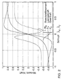
- FIG. 2 shows the lateral or lateral force F y and the restoring torque as a function of the slip ⁇ .
- the curves shown are plotted assuming pure longitudinal movement (zero transverse force) or pure transverse movement (zero longitudinal force).
- the values entered were recorded on a drum test bench for a commercially available car tire with constant contact force (also wheel load) and zero camber and constant speed.
- the slip calculated as the input variable of the tire model from the vehicle sizes represents a vectorial variable with a slip component ⁇ x in the longitudinal direction of the wheel and a slip component ⁇ y in the transverse direction of the wheel.
- FIG. 3 takes no lateral forces into account.
- Left of the dashed Line in the block diagram of Figure 3 are the functional blocks of the simulation computer shown, the elements of the test bench are indicated to the right of the line.
- This schematic representation represents a drive shaft of a drive train test bench, the others are only hinted at.
- An internal combustion engine acts on this drive shaft 10.
- a torque-controlled electrical loading machine 20 is on the attached by the motor 10 driven shaft 12 in a conventional manner.
- the loading machine 20 and its not shown Torque control are designed so that the machine torque delivered as quickly as possible to the respective torque setpoint determined by the simulation computer brought.
- the speed on the drive shaft 12 which represents the output speed of the loading machine 20 and the wheel simulated by this, is measured with high resolution for practically every rotational position defined by angle and phase by a speed sensor, not shown, and fed to the simulation computer as wheel angular speed ⁇ R1 and into that entered in this stored tire model 30.
- the tire parameters each characterizing a tire type also flow into the tire model. These tire parameters can be stored in the computer in the form of constants for the respective friction slip curve and / or in the form of the tire characteristics mentioned above.
- the preferably route-dependent roadway parameters represent a further input variable into the tire model 30.
- the vehicle speed v and the tire contact force F Z1 are supplied to the tire model 30 from a vehicle model 40 that takes the vehicle dynamics into account.
- the tire model provides the output torque value M Soll1 and the longitudinal force F X1 transmitted from the tire to the road as output variables.
- the longitudinal force F X1 like the longitudinal forces of the other wheels considered, is fed back into the vehicle model 40 to calculate the vehicle speed v.
- the vehicle speed v is calculated by integrating the difference between the sum of the returned longitudinal forces F Xi and a determined vehicle resistance force with a time constant corresponding to the mass of the vehicle.
- the vehicle resistance force takes into account, for example, the road gradient, the vehicle air resistance and a rolling resistance proportional to the vehicle speed. However, the latter can also be taken into account in the tire model, as already explained above.
- shear force, longitudinal force and restoring torque in the tire model are preferably taken from three-dimensional maps in which these variables are linked to simulate the dynamic tire behavior. Examples of such maps and the corresponding link formulas can be found in the above-mentioned document by M. Würtenberger.
- the output variables of the tire model which are fed back into the vehicle model then result in longitudinal force F x and lateral force F y as well as the restoring torque.
- the coefficients of friction ⁇ x and ⁇ y are terms in which both slip components ⁇ y and ⁇ x occur.
- the shear force F y is therefore reflected in the torque setpoint calculated from F x ( ⁇ x ) and r dyn .
- the influence of the dynamic tire behavior of the tire under consideration on the other tires in the overall control loop is taken into account by returning both force components F x and F y to the vehicle model. This makes it possible to simulate a real four-wheel model.
- the vehicle model then calculates the vehicle speed v as a vector, at least the x and y components being input into the tire model.
- the contact force F z output by the vehicle model for the individual tires changes depending on the lateral tire forces.
- Different tire models can be used for the tires.
- an entire vehicle is always simulated with the four tire models, even if e.g. only one drive side, for example the rear-wheel drive, is built and not every tire "is available.
- the vehicle model can otherwise according to the above writings and the therein extensive literature cited, taking into account those acting on the vehicle Gravitational and aerodynamic forces can be designed to be realistic, to e.g. also the influence of the pitch and roll behavior on the wheel contact force, Consider road gradient, headwind and a road bank slope.
- the conversion of the individual coordinate systems from the outer inertial system to the wheel system can be done in the vehicle model.
- the simulation computer and also the intended torque control of the loading machines work as a wheel slip simulation control loop so fast that the steep Increase in the slip-dependent coefficient of friction curve can be followed as realistically as possible can.
- the calculation frequency of the model and the torque rise time optimized.
- a hard coupling is achieved by high loop gain, small one Dead time, short sampling time and high sampling speed of the control loop achieved.
- the cycle time for the The specification of a torque setpoint is preferably less than one millisecond.
- the Sampling and evaluation times of the control loop are preferably based on the the optimal triggering times resulting from the design of the electrical loading machines synchronized. For the rest, measures known from control engineering become such as sampling and dead time elements with a defined delay time, ramps for limitation the maximum rate of change, attenuators and the like used.
- measures known from control engineering become such as sampling and dead time elements with a defined delay time, ramps for limitation the maximum rate of change, attenuators and the like used.
- the connection of the hardware and software components of the control loop to the test bench takes place via fast data interfaces.
Landscapes
- Engineering & Computer Science (AREA)
- Physics & Mathematics (AREA)
- Theoretical Computer Science (AREA)
- Geometry (AREA)
- General Physics & Mathematics (AREA)
- Mechanical Engineering (AREA)
- General Engineering & Computer Science (AREA)
- Computer Hardware Design (AREA)
- Evolutionary Computation (AREA)
- Pure & Applied Mathematics (AREA)
- Mathematical Optimization (AREA)
- Mathematical Analysis (AREA)
- Computational Mathematics (AREA)
- Aviation & Aerospace Engineering (AREA)
- Automation & Control Theory (AREA)
- Control Of Driving Devices And Active Controlling Of Vehicle (AREA)
- Tires In General (AREA)
- Management, Administration, Business Operations System, And Electronic Commerce (AREA)
- Testing Of Engines (AREA)
- Electric Propulsion And Braking For Vehicles (AREA)
Abstract
Description
Die Erfindung betrifft ein Verfahren zum Simulieren des Verhaltens eines Fahrzeugs auf einer Fahrbahn auf einem Antriebsstrang-Prüfstand.The invention relates to a method for simulating the behavior of a vehicle a roadway on a drivetrain test bench.
Neben den weiter unten abgehandelten Simulationsverfahren auf einem Antriebsstrang-Prüfstand
sind aus der DE 43 25 413 C2 und DE 40 30 653 A1 mathematische Abschätzungsverfahren
für direkt nicht meßbare, das reale Fahrverhalten charakterisierende
Größen entnehmbar. Hierzu werden die meßtechnisch zugänglichen Sensorsignale mit
Bewegungsgleichungen und unter Einbeziehung eines Reifenmodells so verarbeitet, daß
sich die gewünschten Größen ergeben. Um zu einem Satz lösbarer Gleichungen für die
gewünschten Größen zu gelangen, werden in der DE 43 25 413 C2 z.B. die Reifenkräfte
und der Kraftschlußbeiwert als quasistationär behandelt. Als gemessene Sensorsignale
werden in eine Recheneinheit Signale eingegeben, die die Fahrzeuglängsgeschwindigkeit,
die Längs- und Querbeschleunigung, die Giergeschwindgigkeit, den Lenkwinkel und die
Raddrehzahl der Räder repräsentieren. Um die Bestimmung von den Fahrzustand charakterisierender
Größen in allen Fahrzuständen zu ermöglichen, werden gemäß der DE 43 25
413 C2 die Bewegungsgleichungen durch auf einem Fahrzeugmodell beruhende Meßgleichungen
ergänzt, die mit den Bewegungsgleichungen so kombinierbar sind, daß der erforderliche
Satz Lösungsgleichungen z.B. für den Schwimmwinkel gewonnen werden kann.
Die Meßgleichungen werden aus einem Vierradmodell abgeleitet. Als Zustandsgröße wird
der Neigungswinkel der Fahrbahn gegenüber der Ebene herangezogen. In der DE 40 30
653 A1 wird ein Abschätzungsverfahren für den Schräglaufwinkel der Räder oder der
Achsen eines gebremsten Fahrzeugs sowie für die Seitenführungskräfte an den Rädern
und die Reifenaufstandskräfte angegeben. Es wird ein vereinfachtes Fahrzeugmodell
vorausgesetzt, das Nicken, Wanken und Hubbewegungen nicht berücksichtigt. Seitenführungskraft
und Bremskraft werden aus dem HSRI-Reifenmodell berechnet. Als Meßgrößen
werden die Radgeschwindigkeit, die Giergeschwindigkeit, der Hauptbremszylinderdruck
und die Radbremsdrücke herangezogen. In addition to the simulation procedures dealt with below on a drive train test bench
are from DE 43 25 413 C2 and
Aus der DE 37 00 409 A1 ist ein Bewegungsabschätzsystem entnehmbar, das ein simuliertes Fahrzeug mit einem Satz Fahrzeugbewegungsgleichungen darstellt. Das System verwendet einen Sensor für die einem Rechner direkt zugeführte, gemessene Fahrzeuggeschwindigkeit und einen Sensor für den Lenkradwinkel, der einem Lenkmodell zugeführt wird. Der Rechner soll u.a. auch den Seitenschlupfwinkel abschätzen, ferner liefert er einem Rollmodell einen Querbeschleunigungswert. Das Rollmodell ermittelt hieraus einen Fahrzeugrollwinkel, der wiederum dem Rechner zugeführt wird. Der digitale Rechner ist mit analogen Rechenkreisen für das Lenkmodell und Rollmodell verbunden, die zur Simulation dieser Teile des herangezogenen Gesamtmodells dienen und dem digitalen Rechner den Vorderradlenkwinklel und den Rollwinkel für seine Abschätzungen zuführen. Mit Hilfe der gemessenen Fahrzeuggeschwindigkeit schätzt dann der digitale Rechner aus einem ebenen Bewegungsmodell die gewünschten Fahrzeugbewegungsvariablen ab. Eine Schlupfsimulation läßt sich hierdurch nicht realisieren.From DE 37 00 409 A1, a motion estimation system can be found, the one represents a simulated vehicle with a set of vehicle motion equations. The The system uses a sensor for the measured, directly fed to a computer Vehicle speed and a sensor for the steering wheel angle, which is a steering model is fed. Among other things, the calculator should also estimate the side slip angle, furthermore it delivers a lateral acceleration value to a roll model. The roll model is determined from this a vehicle roll angle, which in turn is fed to the computer. The digital one Computer is connected to analog computing circuits for the steering model and rolling model, which serve to simulate these parts of the overall model used and the digital calculator the front wheel steering angle and the roll angle for its estimates respectively. The digital is then estimated using the measured vehicle speed Calculate the desired vehicle motion variables from a flat motion model from. A slip simulation cannot be implemented in this way.
Ferner werden Prüfstände zum Testen des Antriebsstrangs eines Fahrzeuges, in denen
eine Simulation der Fahrwiderstände und des Beschleunigungsverhaltens des Fahrzeugs
sowie der Fahrzeugräder mittels an den Antriebswellen des Fahrzeugs angebrachter
elektrischer Belastungsmaschinen erfolgt, seit etlichen Jahren in der Automobilindustrie
eingesetzt. Einen solchen Prüfstand beschreibt die EP 0 338 373 B1, wobei dort der
Hauptantriebsstrang, die Achsgetriebe, die treibenden Wellen, die Kupplung, das Getriebe
und der Verbrennungsmotor als vorhandene Komponenten mit ihrem realen Verhalten
eingehen. Die Belastungsmaschinen sind drehmomentgeregelte Elektromotoren, denen
von einem Rechner ein Drehmomentsollwert vorgegeben wird. Dieser Wert wird aus einer
Drehzahldifferenz erzeugt, die auf einen Integrierer mit einer zur Federsteifigkeit des
Reifens proportionalen Zeitkonstanten und ein parallelliegendes Proportionalglied mit
einem zur Reifendämpfungskonstanten proportionalen Verstärkungsfaktor gegeben wird.
Der Drehmomentsollwert wird aus der Summe der vom Integrierer und vom Proportionalglied
gelieferten Feder- und Dämpfungsmomente gebildet. Die Drehzahldifferenz ergibt
sich aus der gemessenen Winkelgeschwindigkeit bzw. Drehzahl der Antriebswelle an der
elektrischen Belastungsmaschine und einer der Fahrzeuggeschwindigkeit proportionalen
Winkelgeschwindigkeit. Letztere wird dadurch ermittelt, daß das um die Drehmomentsollwerte
für die simulierten Räder verminderte Fahrwiderstandsmoment in einem Integrierer
mit einer zum Fahrzeugträgheitsmoment proportionalen Zeitkonstanten integriert wird. Furthermore, test benches for testing the drive train of a vehicle, in which
a simulation of the driving resistance and the acceleration behavior of the vehicle
and the vehicle wheels by means of attached to the drive shafts of the vehicle
electrical load machines has been in the automotive industry for several years
used. Such a test stand is described in
Die oben beschriebene Bildung des Drehmoments beruht somit auf einer Drehzahlregelung,
die zwar die Federsteifigkeit und Dämpfung des Reifens in Betracht zieht, jedoch
grundsätzlich den Reifenschlupf außer acht läßt. Um diese Unzulänglichkeit zu überwinden,
ist es aus der EP 0 338 373 B1 ferner bekannt, zur Berücksichtigung eines kinematischen
Reifenschlupfes von der der Fahrzeuggeschwindigkeit proportionalen Winkelgeschwindigkeit
das Produkt aus dieser Winkelgeschwindigkeit und einem Schlupfwert zu
subtrahieren, der als Funktion des Drehmomentsollwerts ermittelt wird, bevor der obige
Drehzahlvergleich anhand der so modifizierten Winkelgeschwindigkeit erfolgt. Hinsichtlich
dieser Berücksichtigung des kinematischen Schlupfes ist als nachteilig herausgestellt, daß
die Momentenaufteilung im Antriebsstrang während des Schlupfens bekannt sein müßte,
um die erwartete Momentenbilanz zur Errechnung des Drehzahlgradienten heranziehen
zu können, daß aber gerade diese Momentenaufteilung insbesondere während dynamischer
Vorgänge oder bei Systemen mit variabler Momentenverteilung (Durchdrehen) nicht
bekannt sei. Ein durchdrehendes oder blockierendes Rad wird deshalb alternativ so simuliert,
daß der Drehmomentsollwert auf ein entsprechendes konstantes Schlupfmoment begrenzt
wird, das aus einem vorgebbaren fahrbahnrepräsentativen Reibwert, einer Radaufstandskraft
und einem Reifenradius berechnet wird. Außer in den Bereichen des übertragenen
Moments, in denen der Begrenzer den Drehzahlregler zur Simulation des Blockierverhaltens
an seine Begrenzung laufen läßt, wird der Reifen schlupffrei simuliert.The formation of the torque described above is therefore based on a speed control,
which takes into account the spring stiffness and damping of the tire, however
basically ignores tire slip. To overcome this shortcoming,
it is also known from
Diese bekannte Art der Berücksichtigung des Reifenschlupfes stellt hinsichtlich der realitätsnahen Nachbildung des Reifens lediglich eine Kompromißlösung dar, so daß in den gegenwärtigen Antriebsstrangprüfständen in der Regel auf eine Reifensimulation verzichtet wird und nur solche Größen des Fahrzeugverhaltens geprüft werden, bei denen der Reifen bzw. Reifenschlupf vernachlässigt werden kann. Zur Vermeidung von unzulässigen Momentenverläufen wird am Prüfstand mit Hilfe von Momentenausgleichsreglern eine Momentenverteilung aufgeprägt, die nur den theoretischen Werten des Antriebsstrangs, nicht aber den realen Verläufen entspricht.This well-known way of taking into account the tire slip represents the realistic Replica of the tire is only a compromise solution, so that in the current powertrain test benches usually do without a tire simulation will and only those variables of vehicle behavior are checked for which the tire or tire slip can be neglected. To avoid impermissible Torque profiles are tested on the test bench with the help of torque compensation controllers a torque distribution imprinted that only the theoretical values of the drive train, but does not correspond to the real courses.
Ansonsten werden an den Prüfständen im übrigen Lastkollektive nachgefahren, deren Daten in Form der Drehzahl und des Drehmoments an den jeweils interessierenden Rädern auf einer repräsentativen Teststrecke konventionell an Fahrzeugen aufgenommen werden, die mit Einrichtungen zur Momenten- und Drehzahlmessung ausgestattet sind. Dann kann der Prüfling auf dem als Belastungsprüfstand betriebenen Prüfstand unter Nachfahren der auf der Strecke realitätsnah aufgenommenen Lastkollektive z.B. hinsichtlich seiner Dauerfestigkeit getestet werden. Auch in der Prüfeinrichtung der DE 38 18 661 A1 erfolgt die Nachbildung von zuvor gemessenen oder errechneten Lastkollektiven an einem Fahrzeugprüfstand. Dies Schrift läßt offen, welche Programme im Rechner der Prüfeinrichtung zugrunde gelegt werden, um die gewünschten Lastkollektive festzulegen und die Stellgrößen für die Stellglieder zu ermitteln. Es wird gemäß dieser Schrift ein Fahrzeugrad mittels Simulationsantrieb, Stellgliedern und Rechner simuliert, welcher keine aktuellen, während der Simulation anfallenden Meßgrößen berücksichtigt. Durch Erzeugung von Querkräften und Momenten an den Stellgliedern werden Aufstands- und Seitenkräfte simuliert, wobei die Simulation jedoch letztlich auf den vorgegebenen Lastkollektiven beruht.Otherwise, load spectra are tracked on the test benches, whose Data in the form of speed and torque on the wheels of interest conventionally recorded on vehicles on a representative test track be equipped with facilities for torque and speed measurement. Then the test object can be tested on the test bench operated as a load test bench Tracing the load collectives realistically recorded on the route e.g. regarding its fatigue strength can be tested. Also in the test facility of DE 38 18 661 A1 replicates previously measured or calculated load spectra a vehicle test bench. This writing leaves open which programs in the computer the Test facility to be used to determine the desired load spectra and determine the manipulated variables for the actuators. It will be according to this scripture Vehicle wheel simulated using a simulation drive, actuators and computer, which none current measured variables occurring during the simulation are taken into account. Through generation lateral forces and moments on the actuators become riot and lateral forces simulated, but the simulation ultimately based on the specified load spectra is based.
Der Erfindung liegt die Aufgabe zugrunde, ein Verfahren anzugeben, das es gestattet, das Verhalten eines Fahrzeugs auf einer Fahrbahn an einem Antriebsstrang-Prüfstand mit die Räder nachbildenden elektrischen Belastungsmaschinen möglichst realitätsnah zu simulieren.The invention has for its object to provide a method that allows the Behavior of a vehicle on a lane on a powertrain test bench with the To simulate electric stress machines simulating wheels as realistically as possible.
Diese Aufgabe wird durch den Gegenstand des Anspruchs 1 gelöst. Vorteilhafte Weiterbildungen
sind in den Unteransprüchen definiert. Erfindungsgemäß wird eine Fahrzeuggeschwindigkeit
in einem Fahrzeugmodell unter Rückführung der in einem Reifenmodell
berechneten, auf die Fahrbahn übertragenen Kraft ermittelt und wiederum dem Reifenmodell
zugeführt, um die im Anspruch 1 definierte Schlupfsimulation zu erzielen. Die auf die
Fahrbahn übertragene Kraft und ein sich für diese Kraft ergebendes Solldrehmoment für
die entsprechende momentengeregelte Belastungsmaschine werden hierzu im Reifenmodell
wiederum aus der Fahrzeuggeschwindigkeit und einer Reifenaufstandskraft für eine
gemessene Raddrehzahl derart bestimmt, daß sich zwischen einem nominellen, der Fahrzeuggeschwindigkeit
entsprechenden Drehzahlwert und der gemessenen Raddrehzahl
eine dem realen Schlupf entsprechende Differenz einregelt.This object is solved by the subject matter of
Das erfindungsgemäße Verfahren vermeidet im Gegensatz zum weiter oben aufgezeigten
Stand der Technik (EP 0 338 373 B1) eine Drehzahlregelung zur Gewinnung eines der
elektrischen Belastungsmaschine vorzugebenden Solldrehmoments. Statt dessen wird
dieses mit Hilfe eines die schlupfabhängige Reibung eines Reifens nachbildenden Reifenmodells
bestimmt. Insbesondere wird im erfindungsgemäßen Verfahren mit diesem Modell
aus der an der Antriebswelle bzw. der elektrischen Maschine gemessenen Raddrehzahl
eine Kraft ermittelt, die bei dieser Raddrehzahl unter Berücksichtigung eines im Realfall
auftretenden bleibenden Schlupfes vom Reifen auf eine Fahrbahn übertragen wird. Hierzu
werden als weitere Eingangsgrößen in das Reifenmodell eine jeweilige Reifenaufstandskraft
und eine Fahrzeuggeschwindigkeit eingegeben.In contrast to the method shown above, the method according to the invention avoids
State of the art (
Im Gegensatz zu der erläuterten bekannten Drehzahlregelung wird im erfindungsgemäßen Verfahren über das Reifenmodell eine sich auch im wahren Fahrbetrieb einstellende Abweichung zwischen einer nominellen fahrzeuggeschwindigkeitsproportionalen Raddrehzahl und der gemessenen Raddrehzahl eingeregelt. Hierdurch gelingt es, einen dem Realfall entsprechenden Fahrbetrieb zu simulieren. Hierbei gehen sowohl die Kontakteigenschaften des Reifens einschließlich des sich ändernden Anteils der Radlauffläche auf der Fahrbahn als auch die jeweilige Fahrsituation (Geradeausfahrt, Kurvenfahrt, unterschiedliche Fahrbahnneigungen und hieraus resultierende variable Radaufstandskräfte) ein. Die in das Reifenmodell eingegebenen Parameter können in die Formeln des jeweiligen Modells eingesetzt werden, um insbesondere die Schlupfabhängigkeit des Reibwerts für die jeweiligen Parameter nachzubilden. Der Verlauf der Reibwertkurven in Abhängigkeit des Schlupfes ist in den unterschiedlichen bekannten Reifenmodellen z.B. dem nach Pacejka, Böhm oder dem HSRI-Modell prinzipiell ähnlich und umfaßt ausgehend vom Schlupf Null einen steilen Anstieg bis zu einem maximalen Reibwert bei einem kritischen Schlupf mit darauf folgendem vergleichsweise mäßigem Abfall des Reibwerts, bis der Schlupf den Wert Eins annimmt. In contrast to the known speed control described in the invention Procedure via the tire model a deviation that also occurs in true driving operation between a nominal vehicle speed proportional wheel speed and the measured wheel speed. This makes it possible for one To simulate real driving operation. Both the contact properties go here of the tire including the changing portion of the wheel tread the road as well as the respective driving situation (straight ahead, cornering, different Road inclinations and resulting variable wheel contact forces) on. The parameters entered in the tire model can be in the formulas of the respective Model are used, in particular, the slip dependence of the coefficient of friction for the respective parameters. The course of the coefficient of friction curves depending the slip is in the different known tire models e.g. therefore Pacejka, Böhm or the HSRI model in principle similar and includes the Zero slip a steep climb up to a maximum coefficient of friction at a critical Slip followed by a comparatively moderate drop in the coefficient of friction until the Slip assumes the value one.
Das erfindungsgemäße Verfahren ist nicht auf ein spezielles Reifenmodell beschränkt. Das Reifenmodell muß allerdings den aufgezeigten prinzipiellen Reibwertverlauf in Abhängigkeit des Schlupfes und einen sich im Realfall einstellenden Schlupf mit einer den jeweiligen Anforderungen entsprechenden Genauigkeit berücksichtigen. Mit Hilfe der Reifenaufstandskraft ist es dann möglich, die vom Reifen unter bestimmten Bedingungen auf die Fahrbahn aufgebrachte Kraft und einen entsprechenden Sollwert für das Drehmoment der den Reifen simulierenden elektrischen Maschine zu bestimmen und damit den Reifen realitätsnah zu simulieren. Es stellt sich dann automatisch im das Drehmoment der elektrischen Belastungsmaschine nachstellenden Regelkreis für jede Drehzahl die unter diesen Bedingungen auftretende bleibende Abweichung der nominellen und ist-Drehzahl des Rades d.h. ein bleibender Schlupf ein.The method according to the invention is not restricted to a special tire model. The tire model must, however, depend on the principle coefficient of friction shown of the slip and a slip that occurs in the real case with one Take into account the accuracy required for the respective requirements. With the help of the tire contact force it is then possible to get the tire on under certain conditions the road force applied and a corresponding setpoint for the torque of the electrical machine simulating the tire and thus the tire to simulate realistically. It then automatically turns into the torque of the electrical Load machine adjusting control loop for each speed that among them Conditions occurring permanent deviation of the nominal and actual speed of the wheel i.e. a permanent slip.
In Germann, St. (1997), "Modellbildung und Modellgestützte Regelung der Fahrzeuglängsdynamik",
VDI-Bericht 12/309, findet sich auf den Seiten 34 ff. und 55 ff. eine Zusammenstellung
beispielhafter Formalismen zur Berücksichtigung des Systems Reifen-Fahrbahn.
Auch sind die Fundstellen für verschiedene empirische und theoretische Reifenmodelle
aufgeführt und verschiedene Modellansätze verglichen. Daneben finden sich
beispielhafte Gleichungen zur Berücksichtigung der Fahrzeuglängs-, Quer- und Vertikalbewegungen.
Zum Modellansatz von Pacejka sind die Werte von speziellen Parametern
dieses Modells abgeschätzt worden und mit theoretisch nach dem Modellansatz ermittelten
Parametern verglichen worden. Der Reifenmodellansatz von Pacejka ist jedoch nur in
möglicher Ansatz, der im erfindungsgemäßen Verfahren herangezogen werden kann. Der
Fachmann kann das von ihm bevorzugte Reifenmodell im übrigen auch so modifizieren
und gegebenenfalls vereinfachen, daß es nur solche Parameter berücksichtigt, die bei der
Simulation auch berücksichtigt werden sollen. Ferner wird insbesondere für die Einbeziehung
der auf den Reifen wirkenden Querkräfte und eines resultierenden Querschlupfes
verwiesen auf M. Würtenberger (1997), "Modellgestützte Verfahren zur Überwachung des
Fahrzustands eines PKW", VDI-Bericht 12/314, speziell Seite 30 bis 41 und Seite 156 bis
158. Auch hier ist auf das Pacejka Modell Bezug genommen.In Germann, St. (1997), "Modeling and Model-Based Control of Longitudinal Vehicle Dynamics",
VDI
Ein weiterer Vorteil der erfindungsgemäßen Erzeugung des Drehmomentsollwerts aus einem den Schlupf einbeziehenden Reifenmodell besteht darin, daß die Verzögerung der Momentänderung entsprechend der Latsch-Verschiebung, des veränderlichen Anteils der Radlauffläche mit Kontakt zur Straße, durch das Reifenmodell simuliert werden kann. Another advantage of the generation of the torque setpoint according to the invention a slip tire model is that the deceleration of the Torque change according to the Latsch shift, the changing part of the Wheel tread in contact with the road, through which the tire model can be simulated.
Hierbei kann auch der durch die Abplattung der Reifenaufstandsfläche sich jeweils einstellende dynamische Reifenradius berücksichtigt werden. Die erfindungsgemäß bestimmte, von den Reifen im Realfall auf die Fahrbahn übertragene Kraft wird in ein gespeichertes Fahrzeugmodell eingegeben, um die dem Reifenmodell zugeführte Fahrzeuggeschwindigkeit zu ermitteln. Vorzugsweise wird hierzu im Fahrzeugmodell die vom Fahrzeuggeschwindigkeitswert abhängige Fahrzeugwiderstandskraft berechnet und von dieser die von den jeweils betrachteten Rädern auf die Fahrbahn übertragenen Kräfte subtrahiert und aus der resultierenden Differenz und der Masse des Fahrzeugs der Fahrzeuggeschwindigkeitswert ermittelt.This can also be the result of the flattening of the tire contact patch dynamic tire radius are taken into account. The determined according to the invention In real cases, the force transmitted from the tires to the road is stored in a stored Vehicle Model entered the vehicle speed supplied to the tire model to investigate. For this, the vehicle model is preferably used for this purpose Vehicle speed value dependent vehicle drag force calculated and from this is the forces transmitted from the wheels in question to the road subtracted and from the resulting difference and the mass of the vehicle Vehicle speed value determined.
Die Reifenaufstandskraft kann im die Fahrzeugdynamik berücksichtigenden Fahrzeugmodell für jeden Reifen abhängig von der Fahrsituation ermittelt werden, so daß die Schlupfsimulation für jeden Reifen möglich ist, ohne die Momentenverteilung vorab zu kennen oder abschätzen zu müssen. Eine realistische Momentenverteilung stellt sich vielmehr durch diese Art der erfindungsgemäßen Schlupfsimulation von selbst ein.The tire contact force can be in the vehicle model taking into account the vehicle dynamics be determined for each tire depending on the driving situation, so that the slip simulation is possible for every tire without knowing the torque distribution beforehand or to have to estimate. Rather, a realistic distribution of moments arises by this type of slip simulation according to the invention.
Ein besonderer Vorteil des erfindungsgemäßen Verfahrens besteht darin, daß im Reifenmodell nicht nur die Abhängigkeit der Eigenschaften des schlupfenden Rades von Last und Raddrehzahl sowie der Fahrzeuggeschwindigkeit nachgebildet werden können, sondern auch vom Schräglaufwinkel des Rades bzw. Reifens. Der Schräglaufwinkel ist der Winkel zwischen dem Vektor der Radgeschwindigkeit und der Radlängsachse (wie auf Seite 34 des oben zitierten VDI-Berichts von Würtemberger angegeben.) So wird bei dieser Weiterbildung des erfindungsgemäßen Verfahrens die Fahrzeuggeschwindigkeit als Vektor in das Reifenmodell eingegeben, das zusätzlich zu einer Längs- oder Umfangskraft des Reifens auch eine Quer- oder Seitenkraft des Reifens ermittelt. Der resultierende Kraftvektor wird in das Fahrzeugmodell zurückgeführt, das unter Berücksichtigung dieses Kraftvektors den translatorischen Geschwindigkeitsvektor des Rades ermittelt. Hierdurch können auf das Fahrzeug und jeden einzelnen Reifen wirkende Querkräfte berücksichtigt werden.A particular advantage of the method according to the invention is that in the tire model not just the dependence of the properties of the slipping wheel on the load and wheel speed and vehicle speed can be reproduced, but also from the slip angle of the wheel or tire. The slip angle is the Angle between the vector of the wheel speed and the longitudinal axis (as on Page 34 of the above-mentioned VDI report by Würtemberger.) So at this development of the method according to the invention the vehicle speed as Vector entered into the tire model, in addition to a longitudinal or circumferential force a lateral or lateral force of the tire is also determined. The resulting one Force vector is fed back into the vehicle model, taking this into account Force vector determines the translatory speed vector of the wheel. Hereby can take lateral forces acting on the vehicle and each individual tire into account become.
Dem Fahrzeugmodell wird zur Berücksichtigung der Querkräfte auch der Lenkradwinkel zugeführt. Der sich für jedes Rad einstellende Schräglaufwinkel wird dann im Fahrzeugmodell aus dem Lenkradwinkel bzw. dem hieraus resultierenden Radeinschlagwinkel ermittelt und in das Reifenmodell eingegeben. To take the lateral forces into account, the steering wheel angle is also taken into account in the vehicle model fed. The slip angle that arises for each wheel is then in the vehicle model determined from the steering wheel angle or the resulting steering angle and entered into the tire model.
Ein Vorteil ergibt sich auch, wenn die Rollwiderstandskraft in Abhängigkeit von der Reifenaufstandskraft und der Raddrehzahl im Reifenmodell für jeden Reifen ermittelt und bei der vom jeweiligen Reifen auf die Fahrbahn übertragenen Kraft berücksichtigt wird. Bisher hat man ein dem Rollwiderstand entsprechendes Moment pauschal aus der Fahrzeuggeschwindigkeit bestimmt und in einem Gesamt-Fahrzeugwiderstandsmoment berücksichtigt.An advantage also arises if the rolling resistance force is dependent on the tire contact force and the wheel speed in the tire model for each tire and at force transmitted from the respective tire to the road surface is taken into account. So far one lumps a moment corresponding to the rolling resistance from the vehicle speed determined and taken into account in an overall vehicle drag torque.
Bevorzugt werden die Reifenparameter für das Reifenmodell in Form von Modellkonstanten für die Beziehung zwischen Schlupf und Reibwert, dem Reifenradius, einem Reifenkennfeld für die vom Reifen auf die Fahrbahn übertragene Längskraft und für das Reifenrückstellmoment und vorzugsweise auch einem Reifenkennfeld für die vom Reifen auf die Fahrbahn übertragene Querkraft gespeichert.The tire parameters for the tire model are preferred in the form of model constants for the relationship between slip and coefficient of friction, the tire radius, a tire map for the longitudinal force transferred from the tire to the road and for the tire return torque and preferably also a tire map for those from the tire the lateral force transmitted is saved.
Außer der vom Reifen auf die Fahrbahn aufgebrachten Kraft und dem Solldrehmoment können vom Reifenmodell bedarfsweise auch der Schlupfwert und der sich abhängig von den auf den Reifen einwirkenden Kräften (bedingt durch Aufstandskraft, Luftdruck, Drehzahl usw.) ändernde dynamische Radradius rdyn ausgegeben werden.In addition to the force and the target torque applied by the tire to the road surface, the tire model can also output the slip value and the dynamic wheel radius r dyn depending on the forces acting on the tire (due to contact force, air pressure, speed, etc.).
Somit ist es mit dem erfindungsgemäßen Verfahren nicht nur möglich, verschiedene Antriebssysteme zu analysieren, sondern auch unterschiedlichste Fahrbahnbeläge und Straßenzustände in variierenden Fahrsituationen zu berücksichtigen. Darüber hinaus können Streckenprofile unabhängig von Prüfling und Straßenzustand aufgenommen werden. So können beispielsweise mit GPS (Global Position System) aufgenommene Streckendaten in den Simulationsrechner eingegeben werden und mit beliebigen ebenfalls eingegebenen Fahrzeug- und Reifendaten kombiniert werden. Damit können am Prüfstand Kombinationen von unterschiedlichen Prüflingen und Strecken simuliert werden. Dies stellt einen entscheidenden Vorteil gegenüber der bisherigen Praxis des Abfahrens einer Strecke mit realen Fahrzeugen unter Aufnahme der Lastkollektive und des Nachfahrens dieser Lastkollektive auf einem Prüfstand dar. Somit können erfindungsgemäß Prüflinge getestet werden, für die es noch kein Fahrzeug und keine aufgenommenen Lastkollektive gibt. Auch können die Fahrbahneigenschaften (z.B. trockene oder nasse Oberflächen) in der Simulation beliebig abgeändert werden. It is therefore not only possible with the method according to the invention, different drive systems to analyze, but also different road surfaces and road conditions to be taken into account in varying driving situations. In addition, you can Route profiles can be recorded regardless of the test object and road conditions. So can, for example, route data recorded with GPS (Global Position System) be entered into the simulation computer and with any other input that is also entered Vehicle and tire data can be combined. This enables combinations on the test bench of different test objects and routes are simulated. This represents one decisive advantage over the previous practice of driving a route with real vehicles including the load spectra and the descendants of these load spectra on a test bench. Test objects can thus be tested according to the invention for which there is still no vehicle and no recorded load spectra. The road properties (e.g. dry or wet surfaces) in the Simulation can be modified as required.
Ferner ermöglicht das erfindungsgemäße Verfahren, jeden einzelnen Reifen auch hinsichtlich Reifenaufstandskraft und Rollwiderstand individuell zu berücksichtigen.Furthermore, the method according to the invention also enables each individual tire to be considered Tire contact force and rolling resistance to be considered individually.
Im Bedarfsfall kann das Fahrzeugmodell auch den Schwimmwinkel liefern.If necessary, the vehicle model can also supply the float angle.
Im folgenden wird die Erfindung anhand der Zeichnungen näher erläutert. Es zeigen
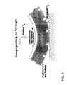
In Figur 1 ist der einfachere Fall dargestellt, daß durch den Reifen nur eine Längskraft Fx und nicht auch eine Querkraft auf die Fahrbahn übertragen wird. Bekanntermaßen tritt bedingt durch die Gummireibung des Reifens auf der Fahrbahn ein Schlupf in Form einer Relativbewegung zwischen Reifen und Fahrbahnoberfläche auf. Die Radaufstandskraft Fz und die Längskraft Fx sind über den Reibwert µ miteinander verknüpft. Dieser ist jedoch nicht konstant, sondern schlupfabhängig. Diese Abhängigkeit vom Schlupf λ wird erfindungsgemäß unter Heranziehen eines der weiter oben aufgezeigten Reifenmodelle nachgebildet.In Figure 1, the simpler case is shown that only a longitudinal force F x and not a transverse force is transmitted to the road by the tire. As is known, the rubber friction of the tire causes slippage in the form of a relative movement between the tire and the road surface. The wheel contact force F z and the longitudinal force F x are linked with each other via the coefficient of friction µ. However, this is not constant, but is dependent on slip. This dependency on the slip λ is simulated according to the invention using one of the tire models shown above.
Die Figur 2 zeigt neben dem Verlauf der Längs- oder Umfangskraft Fx als Ausgangsgröße eines statischen Reifenmodells auch die Quer- oder Seitenkraft Fy sowie das Rückstellmoment als Funktion des Schlupfes λ. Die gezeigten Verläufe sind unter der Annahme reiner Längsbewegung (Querkraft null) oder reiner Querbewegung (Längskraft null) aufgetragen. Die aufgetragenen Werte wurden auf einem Trommelprüfstand für einen kommerziell erhältlichen PKW-Reifen bei konstanter Aufstandskraft (auch Radlast) und Sturz von null sowie konstanter Geschwindigkeit aufgenommen. Der als Eingangsgröße des Reifenmodells aus den Fahrzeuggrößen berechnete Schlupf stellt eine vektorielle Größe dar mit einer Schlupfkomponente λx in Radlängsrichtung und einer Schlupfkomponente λy in Radquerrichtung.In addition to the course of the longitudinal or circumferential force F x as the output variable of a static tire model, FIG. 2 also shows the lateral or lateral force F y and the restoring torque as a function of the slip λ. The curves shown are plotted assuming pure longitudinal movement (zero transverse force) or pure transverse movement (zero longitudinal force). The values entered were recorded on a drum test bench for a commercially available car tire with constant contact force (also wheel load) and zero camber and constant speed. The slip calculated as the input variable of the tire model from the vehicle sizes represents a vectorial variable with a slip component λ x in the longitudinal direction of the wheel and a slip component λ y in the transverse direction of the wheel.
Der Übersichtlichkeit halber berücksichtigt die Figur 3 keine Querkräfte. Links von der gestrichelten
Linie im Blockschaltbild der Figur 3 sind die Funktionsblöcke des Simulationsrechners
dargestellt, rechts von der Linie die Elemente des Prüfstands angedeutet. Dabei
repräsentiert diese schematische Darstellung eine Antriebswelle eines Antriebstrangprüfstandes,
die anderen sind lediglich angedeutet. Auf diese Antriebswelle wirkt ein Verbrennungsmotor
10. Eine drehmomentgeregelte elektrische Belastungsmaschine 20 ist an der
vom Motor 10 angetriebenen Welle 12 in an sich bekannter Weise angebracht. Vorzugsweise
entspricht die Trägheit dieser Maschine in etwa der eines Rades, so daß durch die
Maschine die Drehbewegung des Rades als dynamisches System real nachgebildet wird
und nicht simuliert zu werden braucht. Die Belastungsmaschine 20 und deren nicht dargestellte
Drehmomentregelung sind so ausgelegt, daß das abgegebene Maschinenmoment
schnellstmöglich auf den jeweiligen, vom Simulationsrechner bestimmten Drehmomentsollwert
gebracht wird.For the sake of clarity, FIG. 3 takes no lateral forces into account. Left of the dashed
Line in the block diagram of Figure 3 are the functional blocks of the simulation computer
shown, the elements of the test bench are indicated to the right of the line. there
this schematic representation represents a drive shaft of a drive train test bench,
the others are only hinted at. An internal combustion engine acts on this
Die Drehzahl an der Antriebswelle 12, die die Ausgangsdrehzahl der Belastungsmaschine
20 und des durch diese simulierten Rades darstellt, wird zeitlich hochaufgelöst für praktisch
jede durch Winkel und Phase definierte Drehposition von einem nicht dargestellten
Drehzahlsensor gemessen und als Radwinkelgeschwindigkeit ωR1 dem Simulationsrechner
zugeführt und in das in diesem gespeicherte Reifenmodell 30 eingegeben. In das
Reifenmodell fließen ferner die jeweils einen Reifentyp kennzeichnenden Reifenparameter
ein. Diese Reifenparameter können in Form von Konstanten für die jeweilige Reibwertschlupfkurve
und/ oder in Form der weiter oben erwähnten Reifenkennfelder im Rechner
gespeichert sein. Die vorzugsweise streckenabhängigen Fahrbahnparameter stellen eine
weitere Eingangsgröße in das Reifenmodell 30 dar. Aus einem die Fahrzeugdynamik berücksichtigenden
Fahrzeugmodell 40 werden dem Reifenmodell 30 die Fahrzeuggeschwindigkeit
v und die Reifenaufstandskraft FZ1 zugeführt. Das Reifenmodell liefert als
Ausgangsgrößen den Drehmomentsoliwert MSoll1 und die vom Reifen auf die Fahrbahn
übertragene Längskraft FX1. Die Längskraft FX1 wird wie auch die Längskräfte der übrigen
berücksichtigten Räder zur Berechnung der Fahrzeuggeschwindigkeit v in das Fahrzeugmodell
40 rückgeführt. Bei einer bevorzugten Ausführungsform wird die Fahrzeuggeschwindigkeit
v dadurch berechnet, daß die Differenz zwischen der Summe der rückgeführten
Längskräfte FXi und einer ermittelten Fahrzeugwiderstandskraft mit einer der Masse
des Fahrzeugs entsprechenden Zeitkonstante integriert wird. Die Fahrzeugwiderstandskraft
berücksichtigt beispielsweise die Fahrbahnsteigung, den Fahrzeugluftwiderstand
und einen zur Fahrzeuggeschwindigkeit proportionalen Rollwiderstand. Letzterer
kann jedoch auch im Reifenmodell berücksichtigt werden, wie weiter oben bereits
dargelegt wurde.The speed on the
Bei Berücksichtigung der oben aufgezeigten Querkraftkomponente und der resultierenden Schlupfkomponente λy in Radquerrichtung werden Querkraft, Längskraft und Rückstellmoment im Reifenmodell vorzugsweise aus dreidimensionalen Kennfeldern entnommen, in denen diese Größen zur Simulation des dynamischen Reifenverhaltens verknüpft sind. Beispiele für derartige Kennfelder sowie auch die entsprechenden Verknüpfungsformeln sind der oben genannten Schrift von M. Würtenberger entnehmbar. Als in das Fahrzeugmodell rückgeführte Ausgangsgrößen des Reifenmodells ergeben sich dann Längskraft Fx und Querkraft Fy sowie das Rückstellmoment. Die Reibwerte µx und µy sind Terme, in denen beide Schlupfkomponenten λy und λx auftreten. Daher schlägt sich im aus Fx( µx) und rdyn berechneten Drehmomentsollwert die Querkraft Fy nieder. Über die Rückführung beider Kraftkomponenten Fx und Fy in das Fahrzeugmodell wird der Einfluß des dynamischen Reifenverhaltens des betrachteten Reifens auf die anderen Reifen im Gesamtregelkreis berücksichtigt. Hiermit wird es möglich, ein echtes Vierradmodell zu simulieren. Das Fahrzeugmodell errechnet dann die Fahrzeuggeschwindigkeit v als Vektor, wobei zumindest die x- und y-Komponente in das Reifenmodell eingegeben werden. Die vom Fahrzeugmodell ausgegebene Aufstandkraft Fz für die einzelnen Reifen ändert sich in Abhängigkeit der Reifenquerkräfte.Taking into account the shear force component shown above and the resulting slip component λ y in the wheel transverse direction, shear force, longitudinal force and restoring torque in the tire model are preferably taken from three-dimensional maps in which these variables are linked to simulate the dynamic tire behavior. Examples of such maps and the corresponding link formulas can be found in the above-mentioned document by M. Würtenberger. The output variables of the tire model which are fed back into the vehicle model then result in longitudinal force F x and lateral force F y as well as the restoring torque. The coefficients of friction µ x and µ y are terms in which both slip components λ y and λ x occur. The shear force F y is therefore reflected in the torque setpoint calculated from F x (µ x ) and r dyn . The influence of the dynamic tire behavior of the tire under consideration on the other tires in the overall control loop is taken into account by returning both force components F x and F y to the vehicle model. This makes it possible to simulate a real four-wheel model. The vehicle model then calculates the vehicle speed v as a vector, at least the x and y components being input into the tire model. The contact force F z output by the vehicle model for the individual tires changes depending on the lateral tire forces.
Für die Reifen können unterschiedliche Reifenmodelle verwendet werden. Vorzugsweise wird immer ein ganzes Fahrzeug mit den vier Reifenmodellen simuliert, auch wenn z.B. nur eine Antriebsseite, beispielsweise der Heckantrieb, aufgebaut ist und nicht jeder Reifen "vorhanden" ist.Different tire models can be used for the tires. Preferably an entire vehicle is always simulated with the four tire models, even if e.g. only one drive side, for example the rear-wheel drive, is built and not every tire "is available.
Das Fahrzeugmodell kann im übrigen entsprechend der obigen Schriften und der darin zitierten umfangreichen Literatur unter Berücksichtigung von auf das Fahrzeug einwirkenden Gravitations- und aerodynamischen Kräfte beliebig wirklichkeitsnah gestaltet werden, um z.B. auch die Einwirkung des Nick- und Wankverhaltens auf die Radaufstandskraft, Fahrbahnsteigung, Gegenwind und eine Fahrbahnquerneigung zu berücksichten. Die Umrechnung der einzelnen Koordinatensysteme vom äußeren Inertialsystem bis zum Radsystem kann im Fahrzeugmodell erfolgen. The vehicle model can otherwise according to the above writings and the therein extensive literature cited, taking into account those acting on the vehicle Gravitational and aerodynamic forces can be designed to be realistic, to e.g. also the influence of the pitch and roll behavior on the wheel contact force, Consider road gradient, headwind and a road bank slope. The conversion of the individual coordinate systems from the outer inertial system to the wheel system can be done in the vehicle model.
Der Simulationsrechner und auch die vorgesehene Drehmomentregelung der Belastungsmaschinen arbeiten als Radschlupfsimulationsregelkreis so schnell, daß der steile Anstieg der schlupfabhängigen Reibwertkurve möglichst realitätsnah nachgefahren werden kann. Zu diesem Zweck werden die Rechenfrequenz des Modells und die Momentenanregelzeit optimiert. Eine harte Ankopplung wird durch hohe Kreisverstärkung, kleine Totzeit, kurze Abtastzeit und hohe Abtastgeschwindigkeit des Regelkreises erzielt. In einer Implementierung der Erfindung wurde mit einer Verstärkung von 200 Nm/rads, einer Totzeit von 0,6 ms und einer Abtastrate von 3 kHz gearbeitet. Die Zykluszeit für die Vorgabe eines Drehmomentsollwerts liegt vorzugsweise unter einer Millisekunde. Die Abtast- und Auswertezeitpunkte des Regelkreises werden vorzugsweise mit den sich aus der Bauart der elektrischen Belastungsmaschinen ergebenden optimalen Ansteuerzeitpunkten synchronisiert. Im übrigen werden aus der Regelungstechnik bekannte Maßnahmen wie Abtast- und Totzeitglieder mit definierter Verzögerungszeit, Rampen zur Begrenzung der maximalen Änderungsgeschwindigkeit, Dämpfungsglieder und dergleichen eingesetzt. Die Anbindung der Hardware- und Softwarekomponenten des Regelkreises an den Prüfstand erfolgt über schnelle Datenschnittstellen.The simulation computer and also the intended torque control of the loading machines work as a wheel slip simulation control loop so fast that the steep Increase in the slip-dependent coefficient of friction curve can be followed as realistically as possible can. For this purpose the calculation frequency of the model and the torque rise time optimized. A hard coupling is achieved by high loop gain, small one Dead time, short sampling time and high sampling speed of the control loop achieved. In a Implementation of the invention was done with a gain of 200 Nm / rads, one Dead time of 0.6 ms and a sampling rate of 3 kHz worked. The cycle time for the The specification of a torque setpoint is preferably less than one millisecond. The Sampling and evaluation times of the control loop are preferably based on the the optimal triggering times resulting from the design of the electrical loading machines synchronized. For the rest, measures known from control engineering become such as sampling and dead time elements with a defined delay time, ramps for limitation the maximum rate of change, attenuators and the like used. The connection of the hardware and software components of the control loop to the test bench takes place via fast data interfaces.
Claims (9)
Applications Claiming Priority (2)
| Application Number | Priority Date | Filing Date | Title |
|---|---|---|---|
| DE19910967A DE19910967C1 (en) | 1999-03-12 | 1999-03-12 | Method for simulating the behavior of a vehicle on a road |
| DE19910967 | 1999-03-12 |
Publications (3)
| Publication Number | Publication Date |
|---|---|
| EP1037030A2 true EP1037030A2 (en) | 2000-09-20 |
| EP1037030A3 EP1037030A3 (en) | 2002-02-20 |
| EP1037030B1 EP1037030B1 (en) | 2006-08-02 |
Family
ID=7900673
Family Applications (1)
| Application Number | Title | Priority Date | Filing Date |
|---|---|---|---|
| EP00103567A Expired - Lifetime EP1037030B1 (en) | 1999-03-12 | 2000-02-19 | Procedure for simulating the behaviour of a vehicle on a roadway |
Country Status (4)
| Country | Link |
|---|---|
| US (1) | US6754615B1 (en) |
| EP (1) | EP1037030B1 (en) |
| JP (1) | JP4320406B2 (en) |
| DE (2) | DE19910967C1 (en) |
Cited By (22)
| Publication number | Priority date | Publication date | Assignee | Title |
|---|---|---|---|---|
| WO2001096128A1 (en) * | 2000-06-14 | 2001-12-20 | Sumitomo Rubber Industries, Ltd | Vehicle/tire performances simulating method |
| EP1382955A2 (en) * | 2002-07-19 | 2004-01-21 | AVL List GmbH | Procedure and device for simulating the driving performance of vehicles |
| EP2085255A1 (en) * | 2008-01-31 | 2009-08-05 | Renault | Method for calibrating a signal for detecting a puncture in a vehicle tyre |
| EP2161560A2 (en) * | 2008-09-09 | 2010-03-10 | Zf Friedrichshafen Ag | Method for operating a test stand for vehicle power transmissions |
| ITBO20090769A1 (en) * | 2009-11-27 | 2011-05-28 | Corghi Spa | APPARATUS AND PROCEDURE TO PROVIDE INDICATIONS TO A PERSON FOR A STATIC REGULATION OF A MOTOR VEHICLE EQUIPPED WITH WHEELS WITH TIRES. |
| WO2011151240A1 (en) * | 2010-05-31 | 2011-12-08 | Avl List Gmbh | Method for verifying drive train systems |
| WO2013024220A1 (en) * | 2011-08-17 | 2013-02-21 | Renault S.A.S. | Method of estimating the rolling resistance of a wheel of a motor vehicle and device to implement this method |
| CN101821600B (en) * | 2007-10-12 | 2013-03-13 | 卡特彼勒公司 | Systems and methods for improving haul road conditions |
| WO2013041802A1 (en) * | 2011-09-22 | 2013-03-28 | Renault S.A.S. | Method for estimating the rolling resistance of a vehicle wheel |
| WO2013144469A1 (en) * | 2012-03-27 | 2013-10-03 | Renault S.A.S. | Method for estimating the rolling resistance of wheels of a vehicle wheelset |
| CN101566511B (en) * | 2008-04-25 | 2013-11-13 | 福特全球技术公司 | System and method for tire cornering power estimation and monitoring |
| EP1975825A3 (en) * | 2007-03-28 | 2015-07-22 | The Yokohama Rubber Co., Ltd. | Tire model determining method, tire transient response data calculating method, tire evaluating method, and tire designing method |
| EP2264421A3 (en) * | 2009-06-16 | 2015-08-05 | AVL List GmbH | Test facility assembly |
| AT515712A1 (en) * | 2014-04-16 | 2015-11-15 | Seibt Kristl & Co Gmbh | Method for simulating vehicle behavior and vehicle test bench |
| WO2016102555A1 (en) * | 2014-12-22 | 2016-06-30 | Avl List Gmbh | Method and device for performing a test run on a test stand |
| CN107576863A (en) * | 2017-06-05 | 2018-01-12 | 上海大学 | The safe simulation experiment system of vehicle power |
| CN107941507A (en) * | 2017-12-30 | 2018-04-20 | 横店集团英洛华电气有限公司 | The double shaft synchronized loading simulators of scooter drive axle |
| AT519261B1 (en) * | 2016-12-05 | 2018-05-15 | Avl List Gmbh | Method and test bench for carrying out a test run with a drive train |
| CN111523207A (en) * | 2020-04-08 | 2020-08-11 | 奇瑞汽车股份有限公司 | Method, device, equipment and medium for modeling complete vehicle platform and detecting vehicle performance |
| CN113093708A (en) * | 2021-04-06 | 2021-07-09 | 哈尔滨理工大学 | Multi-signal fusion hub motor automobile torque distribution system and prospective control method |
| AT524086A1 (en) * | 2020-08-14 | 2022-02-15 | Avl List Gmbh | Test stand for testing a real test specimen in driving operation |
| CN114861335A (en) * | 2022-07-11 | 2022-08-05 | 岚图汽车科技有限公司 | Calibration method of automobile dynamics calculation model and related equipment |
Families Citing this family (68)
| Publication number | Priority date | Publication date | Assignee | Title |
|---|---|---|---|---|
| DE10148091A1 (en) * | 2001-09-28 | 2003-04-17 | Bayerische Motoren Werke Ag | Method for determining the mass of a motor vehicle taking into account different driving situations |
| US7222269B2 (en) | 2001-12-06 | 2007-05-22 | Ns Solutions Corporation | Performance evaluation device, performance evaluation information managing device, performance evaluation method, performance evaluation information managing method, performance evaluation system |
| US20040015255A1 (en) * | 2002-01-16 | 2004-01-22 | Ballard Power Systems Corporation | Process for the optimization of the design of an electric power train |
| JP3860518B2 (en) * | 2002-08-12 | 2006-12-20 | 株式会社豊田中央研究所 | Road friction estimation device |
| EP1403100A1 (en) * | 2002-09-27 | 2004-03-31 | Robert Bosch Gmbh | Adaptative tire pressure surveillance |
| DE10328979B4 (en) * | 2003-06-27 | 2021-07-22 | Robert Bosch Gmbh | Method for coordinating a vehicle dynamics control system with an active normal force adjustment system |
| JP3876244B2 (en) * | 2003-09-19 | 2007-01-31 | 横浜ゴム株式会社 | Tire parameter value derivation method, tire cornering characteristic calculation method, tire design method, vehicle motion analysis method, and program |
| JP4140720B2 (en) * | 2004-01-14 | 2008-08-27 | 三菱電機株式会社 | Vehicle behavior reproduction system |
| NL1027648C2 (en) * | 2004-12-03 | 2006-06-07 | Skf Ab | Anti-lock system for a brake of a wheel of a vehicle. |
| US20060173603A1 (en) * | 2005-02-02 | 2006-08-03 | Mohan Sankar K | Slip loss reduction control system for improving driveline efficiency |
| US20060253243A1 (en) * | 2005-05-06 | 2006-11-09 | Jacob Svendenius | System and method for tire/road friction estimation |
| DE102005033995A1 (en) * | 2005-07-21 | 2007-02-01 | Dr.Ing.H.C. F. Porsche Ag | Method and device for controlling a yawing moment actuator in a motor vehicle |
| US7363805B2 (en) * | 2005-09-30 | 2008-04-29 | Ford Motor Company | System for virtual prediction of road loads |
| JP4747798B2 (en) * | 2005-11-22 | 2011-08-17 | 東洋ゴム工業株式会社 | Tire wear test method |
| US7912683B2 (en) * | 2006-03-31 | 2011-03-22 | The Yokohama Rubber Co., Ltd. | Tire transient response data calculating method, data processing method, tire designing method, vehicle motion predicting method, and tire cornering characteristic evaluation method and evaluation device therefor |
| US20070275355A1 (en) * | 2006-05-08 | 2007-11-29 | Langer William J | Integration and supervision for modeled and mechanical vehicle testing and simulation |
| US20070260373A1 (en) * | 2006-05-08 | 2007-11-08 | Langer William J | Dynamic vehicle durability testing and simulation |
| US8001835B2 (en) * | 2006-05-16 | 2011-08-23 | Engstroem Christian | Method and device for dynamometer testing of a motor vehicle and vehicle components |
| DE102006035502B3 (en) * | 2006-07-31 | 2008-04-03 | Dr.Ing.H.C. F. Porsche Ag | Test stand for checking performance of power transmission of motor vehicle, has drive supporting system reproduced with impact on brake of wheel, where braking torque is determined by brake demand of drive supporting system |
| US7778809B2 (en) * | 2006-08-22 | 2010-08-17 | The Yokohama Rubber Co., Ltd. | Tire characteristic calculation method, tire dynamic element parameter value derivation method, vehicle traveling simulation method, and tire designing method and vehicle designing method in which consideration is given to tire friction ellipse |
| DE102007016420B4 (en) | 2007-04-05 | 2011-04-21 | Dr. Ing. H.C. F. Porsche Aktiengesellschaft | Test bench and procedure for testing a drive train |
| WO2008127176A1 (en) * | 2007-04-13 | 2008-10-23 | Engstroem Christian | Method and device for testing of a combustion engine or an associated structure and a rig |
| KR20100021580A (en) * | 2007-05-04 | 2010-02-25 | 엠티에스 시스템즈 코포레이숀 | Method and system for tire evaluation and tuning with loading system and vehicle model |
| US20080275681A1 (en) * | 2007-05-04 | 2008-11-06 | Langer William J | Method and system for vehicle damper system evaluation and tuning with loading system and vehicle model |
| AT9467U3 (en) * | 2007-06-14 | 2008-07-15 | Avl List Gmbh | DEVICE AND METHOD FOR SIMULATING A DEVELOPMENT SYSTEM |
| JP4882886B2 (en) * | 2007-06-26 | 2012-02-22 | 横浜ゴム株式会社 | Tire characteristic determining method and tire characteristic determining apparatus |
| US20090099886A1 (en) * | 2007-10-12 | 2009-04-16 | Caterpillar Inc. | System and method for performance-based payload management |
| DE102007053256B3 (en) * | 2007-11-08 | 2009-07-09 | Continental Automotive Gmbh | Method and device for determining a coefficient of friction |
| US8447578B2 (en) * | 2008-05-07 | 2013-05-21 | Bridgestone Americas Tire Operations, Llc | Method of designing a tire having a target residual aligning torque |
| US9477793B2 (en) | 2008-10-02 | 2016-10-25 | Mts Systems Corporation | Method and systems for off-line control for simulation of coupled hybrid dynamic systems |
| US8135556B2 (en) | 2008-10-02 | 2012-03-13 | Mts Systems Corporation | Methods and systems for off-line control for simulation of coupled hybrid dynamic systems |
| US8712626B2 (en) * | 2009-05-05 | 2014-04-29 | Goodrich Corporation | Autobrake and decel control built-in test equipment |
| AT508031B1 (en) | 2009-10-02 | 2010-10-15 | Seibt Kristl & Co Gmbh | METHOD AND TEST BENCH FOR TRAINING THE DRIVING BEHAVIOR OF A VEHICLE |
| FR2958607B1 (en) * | 2010-04-12 | 2012-03-23 | Renault Sa | TORQUE DISTRIBUTION CONTROL METHOD FOR A MOTORIZED MOTOR VEHICLE WITH FOUR WHEELS AND CORRESPONDING VEHICLE |
| US8806931B2 (en) * | 2010-04-16 | 2014-08-19 | Camber Ridge, Llc | Tire testing systems and methods |
| WO2011159229A1 (en) * | 2010-06-14 | 2011-12-22 | Engstroem Christian | Method and device for dynamometer testing of a motor vehicle |
| JP5467027B2 (en) * | 2010-11-05 | 2014-04-09 | 株式会社ブリヂストン | Tire wear test apparatus, method, and program |
| US8631693B2 (en) * | 2010-12-23 | 2014-01-21 | Horiba Instruments, Inc. | Wheel slip simulation systems and methods |
| US8590369B2 (en) | 2010-12-23 | 2013-11-26 | Horiba Instruments, Inc. | Vehicle drivetrain test stand and method of controlling same |
| ES2580827T3 (en) | 2010-12-30 | 2016-08-29 | Fundación Tecnalia Research & Innovation | System to test and evaluate the behavior and energy efficiency of the propulsion system of an electric hybrid motor vehicle |
| FR2985022B1 (en) * | 2011-12-21 | 2014-02-28 | Peugeot Citroen Automobiles Sa | METHOD OF ESTIMATING THE RESISTANCE COEFFICIENT OF THE BEARING OF A TIRE |
| US10360325B2 (en) | 2012-04-11 | 2019-07-23 | Bridgestone Americas Tire Operations, Llc | System and method for steady state simulation of rolling tire |
| CN104487815B (en) * | 2012-07-09 | 2016-04-13 | 株式会社明电舍 | The pilot system of gear train |
| AT512483B1 (en) | 2013-06-03 | 2015-02-15 | Avl List Gmbh | Method for reducing vibrations in a test bench |
| JP5776731B2 (en) * | 2013-06-19 | 2015-09-09 | 株式会社明電舎 | Drivetrain testing system |
| JP2016529527A (en) | 2013-09-09 | 2016-09-23 | エムティーエス システムズ コーポレイション | Method and system for testing coupled hybrid dynamic systems |
| WO2015035385A1 (en) * | 2013-09-09 | 2015-03-12 | Mts Systems Corporation | Method of off-line hybrid system assessment for test monitoring and modification |
| EP3044564A1 (en) * | 2013-09-09 | 2016-07-20 | MTS Systems Corporation | Test system having a compliant actuator assembly and iteratively obtained drive |
| AT515110B1 (en) | 2014-01-09 | 2015-06-15 | Seibt Kristl & Co Gmbh | Method and device for controlling a powertrain test stand |
| US10377194B2 (en) * | 2014-08-06 | 2019-08-13 | Bridgestone Americas Tire Operations, Llc | Method of modeling tire performance |
| DE102015005019B4 (en) | 2015-04-20 | 2018-12-13 | Audi Ag | Method for determining tire properties |
| CN105004530B (en) * | 2015-07-13 | 2017-10-24 | 北京理工大学 | A kind of haulage vehicle straight-line travelling calculating method of tractive |
| RU2640667C2 (en) * | 2015-12-30 | 2018-01-11 | Федеральное государственное бюджетное образовательное учреждение высшего образования "Московский политехнический университет" | Automated system for controlling loading device for stand tests of automotive power plants |
| AT518792B1 (en) * | 2016-09-12 | 2018-01-15 | Avl List Gmbh | Modular test bench for complete vehicles ready to drive |
| KR101803834B1 (en) * | 2016-12-28 | 2017-12-04 | 부산대학교 산학협력단 | Device for Vehicle Slip Tests in Scaled Environment and Method as the same |
| JP6624152B2 (en) * | 2017-04-26 | 2019-12-25 | 株式会社Soken | Tire-side device and tire device including the same |
| CN107179682B (en) * | 2017-06-20 | 2020-06-02 | 南京理工大学 | Passive load simulator and redundant moment restraining method |
| JP6913550B2 (en) * | 2017-07-14 | 2021-08-04 | 株式会社堀場製作所 | Vehicle drive system test system and vehicle drive system test method |
| EP3501944B1 (en) * | 2017-12-20 | 2020-08-05 | Aptiv Technologies Limited | Method and device for estimating a steering torque |
| PL425275A1 (en) * | 2018-04-19 | 2019-10-21 | Rybka Piotr P.P.H.U. Rybka-Globgum 3 | Car tyre for practice driving and method for making the tread of that tyre |
| CN109522670A (en) * | 2018-11-29 | 2019-03-26 | 山东理工大学 | A kind of wheel hub driving vehicle multi-source excitation Coupling Dynamics Analysis method |
| CN109489877B (en) * | 2018-12-12 | 2021-04-20 | 中国北方车辆研究所 | Method for testing power flow of transmission link of comprehensive transmission device of road test vehicle |
| CN109725221B (en) * | 2019-01-14 | 2020-11-03 | 中车青岛四方机车车辆股份有限公司 | Magnetic suspension test system and electromagnet test method |
| JP7001629B2 (en) | 2019-03-08 | 2022-01-19 | 株式会社堀場製作所 | Specimen test equipment |
| CN111021206B (en) * | 2019-11-20 | 2021-06-25 | 中铁四局集团第一工程有限公司 | Road surface flatness detection method and system |
| CN111368424B (en) * | 2020-03-03 | 2023-09-01 | 阿波罗智能技术(北京)有限公司 | Vehicle simulation method, device, equipment and medium |
| CN111898207B (en) * | 2020-07-31 | 2022-03-15 | 哈尔滨工业大学 | Centroid slip angle estimation method considering dynamic load and road adhesion coefficient |
| CN113032900B (en) * | 2021-03-11 | 2022-04-22 | 华南理工大学 | Air suspension dynamic characteristic simulation method considering inflation and deflation of altitude valve |
Citations (2)
| Publication number | Priority date | Publication date | Assignee | Title |
|---|---|---|---|---|
| DE3812824A1 (en) * | 1988-04-16 | 1989-11-02 | Asea Brown Boveri | TEST TEST FOR TESTING THE DRIVELINE OF A VEHICLE |
| EP0775902A1 (en) * | 1995-11-21 | 1997-05-28 | PIRELLI COORDINAMENTO PNEUMATICI S.p.A. | A method of control to determine the comfort level of a tyre of a wheel for a vehicle |
Family Cites Families (6)
| Publication number | Priority date | Publication date | Assignee | Title |
|---|---|---|---|---|
| JPH0629039B2 (en) | 1986-01-10 | 1994-04-20 | 日産自動車株式会社 | Vehicle motion state estimation device |
| DE3818661A1 (en) * | 1987-06-05 | 1988-12-15 | Zahnradfabrik Friedrichshafen | Test apparatus for driven vehicle axles |
| DE4030653A1 (en) * | 1990-09-28 | 1992-04-02 | Bosch Gmbh Robert | METHOD FOR DETERMINING THE SLOPING ANGLE AND / OR THE SIDE GUIDING FORCE OF A BRAKED VEHICLE |
| DE4325413C2 (en) * | 1993-07-29 | 1995-05-18 | Daimler Benz Ag | Method for determining the behavior of characteristic quantities |
| DE69831642T2 (en) * | 1997-11-25 | 2006-06-29 | Sumitomo Rubber Industries Ltd., Kobe | Method and apparatus for simulating a rolling tire |
| US6083268A (en) * | 1998-04-27 | 2000-07-04 | Bridgestone/Firestone, Inc. | Method for designing pneumatic tires for rolling conditions |
-
1999
- 1999-03-12 DE DE19910967A patent/DE19910967C1/en not_active Expired - Fee Related
-
2000
- 2000-02-19 EP EP00103567A patent/EP1037030B1/en not_active Expired - Lifetime
- 2000-02-19 DE DE50013244T patent/DE50013244D1/en not_active Expired - Lifetime
- 2000-03-09 US US09/522,223 patent/US6754615B1/en not_active Expired - Fee Related
- 2000-03-10 JP JP2000067242A patent/JP4320406B2/en not_active Expired - Lifetime
Patent Citations (2)
| Publication number | Priority date | Publication date | Assignee | Title |
|---|---|---|---|---|
| DE3812824A1 (en) * | 1988-04-16 | 1989-11-02 | Asea Brown Boveri | TEST TEST FOR TESTING THE DRIVELINE OF A VEHICLE |
| EP0775902A1 (en) * | 1995-11-21 | 1997-05-28 | PIRELLI COORDINAMENTO PNEUMATICI S.p.A. | A method of control to determine the comfort level of a tyre of a wheel for a vehicle |
Non-Patent Citations (1)
| Title |
|---|
| ZEGELAAR P W A ET AL: "TYRE MODELS FOR THE STUDY OF IN-PLANE DYNAMICS" VEHICLE SYSTEM DYNAMICS, SWETS AND ZEITLINGER, LISSE, NL, Bd. 23, 23. August 1993 (1993-08-23), Seiten 578-590, XP000605838 ISSN: 0042-3114 * |
Cited By (47)
| Publication number | Priority date | Publication date | Assignee | Title |
|---|---|---|---|---|
| US6725168B2 (en) | 2000-06-14 | 2004-04-20 | Sumitomo Rubber Industries, Ltd. | Vehicle/tire performance simulating method |
| WO2001096128A1 (en) * | 2000-06-14 | 2001-12-20 | Sumitomo Rubber Industries, Ltd | Vehicle/tire performances simulating method |
| EP1382955A2 (en) * | 2002-07-19 | 2004-01-21 | AVL List GmbH | Procedure and device for simulating the driving performance of vehicles |
| EP1382955A3 (en) * | 2002-07-19 | 2004-06-16 | AVL List GmbH | Procedure and device for simulating the driving performance of vehicles |
| EP3699804A3 (en) * | 2007-03-28 | 2020-11-04 | The Yokohama Rubber Co., Ltd. | Tire model determining method, tire transient response data calculating method, tire evaluating method, and tire designing method |
| EP3882803A1 (en) * | 2007-03-28 | 2021-09-22 | The Yokohama Rubber Co., Ltd. | Tire model determining method, tire transient response data calculating method, tire evaluating method, and tire designing method |
| EP3882804A1 (en) * | 2007-03-28 | 2021-09-22 | The Yokohama Rubber Co., Ltd. | Tire model determining method, tire transient response data calculating method, tire evaluating method, and tire designing method |
| EP1975825A3 (en) * | 2007-03-28 | 2015-07-22 | The Yokohama Rubber Co., Ltd. | Tire model determining method, tire transient response data calculating method, tire evaluating method, and tire designing method |
| CN101821600B (en) * | 2007-10-12 | 2013-03-13 | 卡特彼勒公司 | Systems and methods for improving haul road conditions |
| EP2085255A1 (en) * | 2008-01-31 | 2009-08-05 | Renault | Method for calibrating a signal for detecting a puncture in a vehicle tyre |
| FR2927017A1 (en) * | 2008-01-31 | 2009-08-07 | Renault Sas | METHOD FOR CALIBRATING A TIRE DETECTING SIGNAL OF A TIRE OF A VEHICLE |
| CN101566511B (en) * | 2008-04-25 | 2013-11-13 | 福特全球技术公司 | System and method for tire cornering power estimation and monitoring |
| EP2161560A2 (en) * | 2008-09-09 | 2010-03-10 | Zf Friedrichshafen Ag | Method for operating a test stand for vehicle power transmissions |
| EP2264421A3 (en) * | 2009-06-16 | 2015-08-05 | AVL List GmbH | Test facility assembly |
| ITBO20090769A1 (en) * | 2009-11-27 | 2011-05-28 | Corghi Spa | APPARATUS AND PROCEDURE TO PROVIDE INDICATIONS TO A PERSON FOR A STATIC REGULATION OF A MOTOR VEHICLE EQUIPPED WITH WHEELS WITH TIRES. |
| EP2327973A1 (en) * | 2009-11-27 | 2011-06-01 | CORGHI S.p.A. | Apparatus and method for supplying a person with information for statically adjusting a motor vehicle equipped with wheels fitted with tyres. |
| CN102096761B (en) * | 2009-11-27 | 2015-12-02 | 科希股份有限公司 | Supply of behaving is used for carrying out the motor vehicles being equipped with the wheel being equipped with tire equipment and the method for the information of static adjust |
| CN102096761A (en) * | 2009-11-27 | 2011-06-15 | 科希股份有限公司 | Apparatus and method for supplying a person with information for statically adjusting a motor vehicle equipped with wheels fitted with tyres |
| WO2011151240A1 (en) * | 2010-05-31 | 2011-12-08 | Avl List Gmbh | Method for verifying drive train systems |
| WO2013024220A1 (en) * | 2011-08-17 | 2013-02-21 | Renault S.A.S. | Method of estimating the rolling resistance of a wheel of a motor vehicle and device to implement this method |
| FR2979077A1 (en) * | 2011-08-17 | 2013-02-22 | Renault Sa | METHOD FOR ESTIMATING THE ROLLING RESISTANCE OF A MOTOR VEHICLE WHEEL AND DEVICE FOR CARRYING OUT SAID METHOD |
| CN103946039A (en) * | 2011-09-22 | 2014-07-23 | 雷诺两合公司 | Method for estimating the rolling resistance of a vehicle wheel |
| FR2980573A1 (en) * | 2011-09-22 | 2013-03-29 | Renault Sa | METHOD FOR ESTIMATING THE ROLLING RESISTANCE OF A VEHICLE WHEEL |
| WO2013041802A1 (en) * | 2011-09-22 | 2013-03-28 | Renault S.A.S. | Method for estimating the rolling resistance of a vehicle wheel |
| FR2988645A1 (en) * | 2012-03-27 | 2013-10-04 | Renault Sa | METHOD FOR ESTIMATING THE ROLLING RESISTANCE OF WHEELS EQUIPPED WITH A TRAIN OF A VEHICLE |
| WO2013144469A1 (en) * | 2012-03-27 | 2013-10-03 | Renault S.A.S. | Method for estimating the rolling resistance of wheels of a vehicle wheelset |
| AT515712A1 (en) * | 2014-04-16 | 2015-11-15 | Seibt Kristl & Co Gmbh | Method for simulating vehicle behavior and vehicle test bench |
| AT515712B1 (en) * | 2014-04-16 | 2019-04-15 | Seibt Kristl & Co Gmbh | Method for simulating vehicle behavior and vehicle test bench |
| US9841351B2 (en) | 2014-04-16 | 2017-12-12 | Kristl, Seibt & Co. Gesellschaft M.B.H. | Method for simulating the behavior of the vehicle and chassis dynamometer |
| WO2016102555A1 (en) * | 2014-12-22 | 2016-06-30 | Avl List Gmbh | Method and device for performing a test run on a test stand |
| AT516629A4 (en) * | 2014-12-22 | 2016-07-15 | Avl List Gmbh | Method and device for carrying out a test run on a test bench |
| AT516629B1 (en) * | 2014-12-22 | 2016-07-15 | Avl List Gmbh | Method and device for carrying out a test run on a test bench |
| US10502661B2 (en) | 2014-12-22 | 2019-12-10 | Avl List Gmbh | Method and device for performing a test run on a test stand |
| US10962445B2 (en) | 2016-12-05 | 2021-03-30 | Avl List Gmbh | Method for controlling a load machine during a test run with a drive train and test stand |
| AT519261B1 (en) * | 2016-12-05 | 2018-05-15 | Avl List Gmbh | Method and test bench for carrying out a test run with a drive train |
| WO2018104270A1 (en) * | 2016-12-05 | 2018-06-14 | Avl List Gmbh | Method for controlling a load machine during a test run with a drive train and test stand |
| AT519261A4 (en) * | 2016-12-05 | 2018-05-15 | Avl List Gmbh | Method and test bench for carrying out a test run with a drive train |
| CN107576863A (en) * | 2017-06-05 | 2018-01-12 | 上海大学 | The safe simulation experiment system of vehicle power |
| CN107576863B (en) * | 2017-06-05 | 2024-04-19 | 上海大学 | Vehicle power safety simulation test system |
| CN107941507A (en) * | 2017-12-30 | 2018-04-20 | 横店集团英洛华电气有限公司 | The double shaft synchronized loading simulators of scooter drive axle |
| CN111523207A (en) * | 2020-04-08 | 2020-08-11 | 奇瑞汽车股份有限公司 | Method, device, equipment and medium for modeling complete vehicle platform and detecting vehicle performance |
| CN111523207B (en) * | 2020-04-08 | 2023-06-27 | 奇瑞汽车股份有限公司 | Method, device, equipment and medium for modeling whole vehicle platform and detecting vehicle performance |
| AT524086A1 (en) * | 2020-08-14 | 2022-02-15 | Avl List Gmbh | Test stand for testing a real test specimen in driving operation |
| AT524086B1 (en) * | 2020-08-14 | 2022-07-15 | Avl List Gmbh | Test stand for testing a real test specimen in driving operation |
| CN113093708A (en) * | 2021-04-06 | 2021-07-09 | 哈尔滨理工大学 | Multi-signal fusion hub motor automobile torque distribution system and prospective control method |
| CN113093708B (en) * | 2021-04-06 | 2023-03-21 | 哈尔滨理工大学 | Multi-signal fusion hub motor automobile torque distribution test system and prospective control method |
| CN114861335A (en) * | 2022-07-11 | 2022-08-05 | 岚图汽车科技有限公司 | Calibration method of automobile dynamics calculation model and related equipment |
Also Published As
| Publication number | Publication date |
|---|---|
| DE19910967C1 (en) | 2000-09-21 |
| JP4320406B2 (en) | 2009-08-26 |
| EP1037030A3 (en) | 2002-02-20 |
| DE50013244D1 (en) | 2006-09-14 |
| JP2000329656A (en) | 2000-11-30 |
| EP1037030B1 (en) | 2006-08-02 |
| US6754615B1 (en) | 2004-06-22 |
Similar Documents
| Publication | Publication Date | Title |
|---|---|---|
| DE19910967C1 (en) | Method for simulating the behavior of a vehicle on a road | |
| EP3548860B1 (en) | Method for controlling an absorbing dynamometer during a power train test and test bench | |
| DE112013000718B4 (en) | Vehicle control device | |
| EP2978643A1 (en) | Method for determining a vehicle reference speed and vehicle controller having such a method | |
| DE102008041883A1 (en) | Method for operating a test bench for vehicle drive trains | |
| WO2016110488A1 (en) | Method for operating a driving simulator | |
| WO2013174974A1 (en) | Method for testing a vehicle or a component of a vehicle | |
| WO2016102555A1 (en) | Method and device for performing a test run on a test stand | |
| DE19649137A1 (en) | Regulating dynamic behaviour of motor vehicle e.g. around bend | |
| DE102011085103B4 (en) | Method for regulating the driving dynamics of a motor vehicle | |
| EP3132243A1 (en) | Method for simulating the behaviour of the vehicle and chassis dynamometer | |
| DE102011107434A1 (en) | Method and a test platform for the development of a vehicle with multiple driven axles | |
| WO2005063536A1 (en) | Method and device for determining a vehicle state | |
| EP3039398B1 (en) | Method for the simulation of cornering | |
| DE102004006944A1 (en) | Model-based control method and control device for vehicle dynamics control of a multi-lane vehicle | |
| DE3801647C2 (en) | Method and device for testing a four-wheel drive unit | |
| DE102009005889A1 (en) | Method for actively setting an inclination of a wheel of a motor vehicle, in particular of camber and track, and corresponding device | |
| AT519997B1 (en) | Determination of a vehicle longitudinal acceleration on the test bench | |
| AT523916B1 (en) | Method and system for analyzing a driving dynamics driving behavior of a vehicle | |
| EP2450814A2 (en) | Method for generating an excitation profile and method for providing forces and momentum for excitation of motor vehicles | |
| WO2023285606A1 (en) | Method for determining vehicle driving status variables which are not directly measurable | |
| WO2023046422A1 (en) | Method and device for measuring a parameter relevant to the journey of a rail vehicle | |
| WO2023081944A1 (en) | Method for generating a virtual prototype of a vehicle |
Legal Events
| Date | Code | Title | Description |
|---|---|---|---|
| PUAI | Public reference made under article 153(3) epc to a published international application that has entered the european phase |
Free format text: ORIGINAL CODE: 0009012 |
|
| AK | Designated contracting states |
Kind code of ref document: A2 Designated state(s): DE FR GB IT Kind code of ref document: A2 Designated state(s): AT BE CH CY DE DK ES FI FR GB GR IE IT LI LU MC NL PT SE |
|
| AX | Request for extension of the european patent |
Free format text: AL;LT;LV;MK;RO;SI |
|
| PUAL | Search report despatched |
Free format text: ORIGINAL CODE: 0009013 |
|
| AK | Designated contracting states |
Kind code of ref document: A3 Designated state(s): AT BE CH CY DE DK ES FI FR GB GR IE IT LI LU MC NL PT SE |
|
| AX | Request for extension of the european patent |
Free format text: AL;LT;LV;MK;RO;SI |
|
| RIC1 | Information provided on ipc code assigned before grant |
Free format text: 7G 01M 15/00 A, 7G 01M 17/02 B, 7G 01M 13/02 B |
|
| 17P | Request for examination filed |
Effective date: 20020507 |
|
| AKX | Designation fees paid |
Free format text: DE FR GB IT |
|
| GRAP | Despatch of communication of intention to grant a patent |
Free format text: ORIGINAL CODE: EPIDOSNIGR1 |
|
| GRAS | Grant fee paid |
Free format text: ORIGINAL CODE: EPIDOSNIGR3 |
|
| GRAA | (expected) grant |
Free format text: ORIGINAL CODE: 0009210 |
|
| AK | Designated contracting states |
Kind code of ref document: B1 Designated state(s): DE FR GB IT |
|
| PG25 | Lapsed in a contracting state [announced via postgrant information from national office to epo] |
Ref country code: IT Free format text: LAPSE BECAUSE OF FAILURE TO SUBMIT A TRANSLATION OF THE DESCRIPTION OR TO PAY THE FEE WITHIN THE PRESCRIBED TIME-LIMIT;WARNING: LAPSES OF ITALIAN PATENTS WITH EFFECTIVE DATE BEFORE 2007 MAY HAVE OCCURRED AT ANY TIME BEFORE 2007. THE CORRECT EFFECTIVE DATE MAY BE DIFFERENT FROM THE ONE RECORDED. Effective date: 20060802 |
|
| REG | Reference to a national code |
Ref country code: GB Ref legal event code: FG4D Free format text: NOT ENGLISH |
|
| REF | Corresponds to: |
Ref document number: 50013244 Country of ref document: DE Date of ref document: 20060914 Kind code of ref document: P |
|
| GBT | Gb: translation of ep patent filed (gb section 77(6)(a)/1977) |
Effective date: 20061002 |
|
| ET | Fr: translation filed | ||
| PLBE | No opposition filed within time limit |
Free format text: ORIGINAL CODE: 0009261 |
|
| STAA | Information on the status of an ep patent application or granted ep patent |
Free format text: STATUS: NO OPPOSITION FILED WITHIN TIME LIMIT |
|
| 26N | No opposition filed |
Effective date: 20070503 |
|
| REG | Reference to a national code |
Ref country code: FR Ref legal event code: TQ |
|
| REG | Reference to a national code |
Ref country code: FR Ref legal event code: CD |
|
| PGFP | Annual fee paid to national office [announced via postgrant information from national office to epo] |
Ref country code: GB Payment date: 20140328 Year of fee payment: 15 |
|
| PGFP | Annual fee paid to national office [announced via postgrant information from national office to epo] |
Ref country code: FR Payment date: 20140328 Year of fee payment: 15 |
|
| GBPC | Gb: european patent ceased through non-payment of renewal fee |
Effective date: 20150219 |
|
| REG | Reference to a national code |
Ref country code: DE Ref legal event code: R082 Ref document number: 50013244 Country of ref document: DE Representative=s name: KOHLER SCHMID MOEBUS PATENTANWAELTE PARTNERSCH, DE Ref country code: DE Ref legal event code: R081 Ref document number: 50013244 Country of ref document: DE Owner name: AVL DEUTSCHLAND GMBH, DE Free format text: FORMER OWNERS: AVL DEUTSCHLAND GMBH, 55252 MAINZ-KASTEL, DE; DR. ING. H.C. F. PORSCHE AKTIENGESELLSCHAFT, 70435 STUTTGART, DE |
|
| REG | Reference to a national code |
Ref country code: FR Ref legal event code: ST Effective date: 20151030 |
|
| PG25 | Lapsed in a contracting state [announced via postgrant information from national office to epo] |
Ref country code: GB Free format text: LAPSE BECAUSE OF NON-PAYMENT OF DUE FEES Effective date: 20150219 |
|
| PG25 | Lapsed in a contracting state [announced via postgrant information from national office to epo] |
Ref country code: FR Free format text: LAPSE BECAUSE OF NON-PAYMENT OF DUE FEES Effective date: 20150302 |
|
| PGFP | Annual fee paid to national office [announced via postgrant information from national office to epo] |
Ref country code: DE Payment date: 20190226 Year of fee payment: 20 |
|
| REG | Reference to a national code |
Ref country code: DE Ref legal event code: R071 Ref document number: 50013244 Country of ref document: DE |