EP1024262B1 - Estimated mass airflow in turbocharged engines having exhaust gas recirculation - Google Patents
Estimated mass airflow in turbocharged engines having exhaust gas recirculation Download PDFInfo
- Publication number
- EP1024262B1 EP1024262B1 EP00300287A EP00300287A EP1024262B1 EP 1024262 B1 EP1024262 B1 EP 1024262B1 EP 00300287 A EP00300287 A EP 00300287A EP 00300287 A EP00300287 A EP 00300287A EP 1024262 B1 EP1024262 B1 EP 1024262B1
- Authority
- EP
- European Patent Office
- Prior art keywords
- value
- exhaust gas
- calculating
- gas recirculation
- intake manifold
- Prior art date
- Legal status (The legal status is an assumption and is not a legal conclusion. Google has not performed a legal analysis and makes no representation as to the accuracy of the status listed.)
- Expired - Fee Related
Links
Images

Classifications
-
- F—MECHANICAL ENGINEERING; LIGHTING; HEATING; WEAPONS; BLASTING
- F02—COMBUSTION ENGINES; HOT-GAS OR COMBUSTION-PRODUCT ENGINE PLANTS
- F02D—CONTROLLING COMBUSTION ENGINES
- F02D41/00—Electrical control of supply of combustible mixture or its constituents
- F02D41/0002—Controlling intake air
- F02D41/0007—Controlling intake air for control of turbo-charged or super-charged engines
-
- F—MECHANICAL ENGINEERING; LIGHTING; HEATING; WEAPONS; BLASTING
- F02—COMBUSTION ENGINES; HOT-GAS OR COMBUSTION-PRODUCT ENGINE PLANTS
- F02B—INTERNAL-COMBUSTION PISTON ENGINES; COMBUSTION ENGINES IN GENERAL
- F02B37/00—Engines characterised by provision of pumps driven at least for part of the time by exhaust
- F02B37/12—Control of the pumps
- F02B37/24—Control of the pumps by using pumps or turbines with adjustable guide vanes
-
- F—MECHANICAL ENGINEERING; LIGHTING; HEATING; WEAPONS; BLASTING
- F02—COMBUSTION ENGINES; HOT-GAS OR COMBUSTION-PRODUCT ENGINE PLANTS
- F02D—CONTROLLING COMBUSTION ENGINES
- F02D21/00—Controlling engines characterised by their being supplied with non-airborne oxygen or other non-fuel gas
- F02D21/06—Controlling engines characterised by their being supplied with non-airborne oxygen or other non-fuel gas peculiar to engines having other non-fuel gas added to combustion air
- F02D21/08—Controlling engines characterised by their being supplied with non-airborne oxygen or other non-fuel gas peculiar to engines having other non-fuel gas added to combustion air the other gas being the exhaust gas of engine
-
- F—MECHANICAL ENGINEERING; LIGHTING; HEATING; WEAPONS; BLASTING
- F02—COMBUSTION ENGINES; HOT-GAS OR COMBUSTION-PRODUCT ENGINE PLANTS
- F02D—CONTROLLING COMBUSTION ENGINES
- F02D41/00—Electrical control of supply of combustible mixture or its constituents
- F02D41/0025—Controlling engines characterised by use of non-liquid fuels, pluralities of fuels, or non-fuel substances added to the combustible mixtures
- F02D41/0047—Controlling exhaust gas recirculation [EGR]
- F02D41/0065—Specific aspects of external EGR control
- F02D41/0072—Estimating, calculating or determining the EGR rate, amount or flow
-
- F—MECHANICAL ENGINEERING; LIGHTING; HEATING; WEAPONS; BLASTING
- F02—COMBUSTION ENGINES; HOT-GAS OR COMBUSTION-PRODUCT ENGINE PLANTS
- F02D—CONTROLLING COMBUSTION ENGINES
- F02D41/00—Electrical control of supply of combustible mixture or its constituents
- F02D41/02—Circuit arrangements for generating control signals
- F02D41/14—Introducing closed-loop corrections
- F02D41/1438—Introducing closed-loop corrections using means for determining characteristics of the combustion gases; Sensors therefor
- F02D41/1444—Introducing closed-loop corrections using means for determining characteristics of the combustion gases; Sensors therefor characterised by the characteristics of the combustion gases
- F02D41/1448—Introducing closed-loop corrections using means for determining characteristics of the combustion gases; Sensors therefor characterised by the characteristics of the combustion gases the characteristics being an exhaust gas pressure
-
- F—MECHANICAL ENGINEERING; LIGHTING; HEATING; WEAPONS; BLASTING
- F02—COMBUSTION ENGINES; HOT-GAS OR COMBUSTION-PRODUCT ENGINE PLANTS
- F02D—CONTROLLING COMBUSTION ENGINES
- F02D2200/00—Input parameters for engine control
- F02D2200/02—Input parameters for engine control the parameters being related to the engine
- F02D2200/04—Engine intake system parameters
- F02D2200/0402—Engine intake system parameters the parameter being determined by using a model of the engine intake or its components
-
- F—MECHANICAL ENGINEERING; LIGHTING; HEATING; WEAPONS; BLASTING
- F02—COMBUSTION ENGINES; HOT-GAS OR COMBUSTION-PRODUCT ENGINE PLANTS
- F02M—SUPPLYING COMBUSTION ENGINES IN GENERAL WITH COMBUSTIBLE MIXTURES OR CONSTITUENTS THEREOF
- F02M26/00—Engine-pertinent apparatus for adding exhaust gases to combustion-air, main fuel or fuel-air mixture, e.g. by exhaust gas recirculation [EGR] systems
- F02M26/02—EGR systems specially adapted for supercharged engines
- F02M26/04—EGR systems specially adapted for supercharged engines with a single turbocharger
- F02M26/05—High pressure loops, i.e. wherein recirculated exhaust gas is taken out from the exhaust system upstream of the turbine and reintroduced into the intake system downstream of the compressor
-
- F—MECHANICAL ENGINEERING; LIGHTING; HEATING; WEAPONS; BLASTING
- F02—COMBUSTION ENGINES; HOT-GAS OR COMBUSTION-PRODUCT ENGINE PLANTS
- F02M—SUPPLYING COMBUSTION ENGINES IN GENERAL WITH COMBUSTIBLE MIXTURES OR CONSTITUENTS THEREOF
- F02M26/00—Engine-pertinent apparatus for adding exhaust gases to combustion-air, main fuel or fuel-air mixture, e.g. by exhaust gas recirculation [EGR] systems
- F02M26/02—EGR systems specially adapted for supercharged engines
- F02M26/09—Constructional details, e.g. structural combinations of EGR systems and supercharger systems; Arrangement of the EGR and supercharger systems with respect to the engine
- F02M26/10—Constructional details, e.g. structural combinations of EGR systems and supercharger systems; Arrangement of the EGR and supercharger systems with respect to the engine having means to increase the pressure difference between the exhaust and intake system, e.g. venturis, variable geometry turbines, check valves using pressure pulsations or throttles in the air intake or exhaust system
-
- Y—GENERAL TAGGING OF NEW TECHNOLOGICAL DEVELOPMENTS; GENERAL TAGGING OF CROSS-SECTIONAL TECHNOLOGIES SPANNING OVER SEVERAL SECTIONS OF THE IPC; TECHNICAL SUBJECTS COVERED BY FORMER USPC CROSS-REFERENCE ART COLLECTIONS [XRACs] AND DIGESTS
- Y02—TECHNOLOGIES OR APPLICATIONS FOR MITIGATION OR ADAPTATION AGAINST CLIMATE CHANGE
- Y02T—CLIMATE CHANGE MITIGATION TECHNOLOGIES RELATED TO TRANSPORTATION
- Y02T10/00—Road transport of goods or passengers
- Y02T10/10—Internal combustion engine [ICE] based vehicles
- Y02T10/12—Improving ICE efficiencies
-
- Y—GENERAL TAGGING OF NEW TECHNOLOGICAL DEVELOPMENTS; GENERAL TAGGING OF CROSS-SECTIONAL TECHNOLOGIES SPANNING OVER SEVERAL SECTIONS OF THE IPC; TECHNICAL SUBJECTS COVERED BY FORMER USPC CROSS-REFERENCE ART COLLECTIONS [XRACs] AND DIGESTS
- Y02—TECHNOLOGIES OR APPLICATIONS FOR MITIGATION OR ADAPTATION AGAINST CLIMATE CHANGE
- Y02T—CLIMATE CHANGE MITIGATION TECHNOLOGIES RELATED TO TRANSPORTATION
- Y02T10/00—Road transport of goods or passengers
- Y02T10/10—Internal combustion engine [ICE] based vehicles
- Y02T10/40—Engine management systems
Definitions
- This invention relates to turbocharged compression ignition engines having exhaust gas recirculation systems and, more particularly, to methods of estimating the mass air flow into diesel engines equipped with variable geometry turbochargers (VGT) and exhaust gas recirculation (EGR) systems.
- VVT variable geometry turbochargers
- EGR exhaust gas recirculation
- High performance, high speed diesel engines are often equipped with turbochargers to increase power density over a wider engine operating range, and EGR systems to reduce the production of NOx emissions.
- Turbochargers use a portion of the exhaust gas energy to increase the mass of the air charge delivered to the engine combustion chambers.
- the larger mass of air can be burned with a larger quantity of fuel, thereby resulting in increased power and torque as compared to naturally aspirated engines.
- a typical turbocharger consists of a compressor and turbine coupled by a common shaft.
- the exhaust gas drives the turbine which drives the compressor which, in turn, compresses ambient air and directs it into the intake manifold.
- VVT Variable geometry turbochargers
- EGR systems are used to reduce NOx emissions by increasing the dilution fraction in the intake manifold.
- EGR is typically accomplished with an EGR valve that connects the intake manifold and the exhaust manifold.
- the recirculated exhaust gas acts as an inert gas, thus lowering the flame and in-cylinder gas temperature and, hence, decreasing the formation of NOx.
- the recirculated exhaust gas displaces fresh air and reduces the air-to-fuel ratio of the in-cylinder mixture.
- Set points for MAP and MAF are developed by engine mapping which is referenced to fuel demand as well as and engine speed.
- the EGR valve is used to control MAF, and the VGT is used to control MAP.
- Neither EGR flow nor VGT position is typically measured.
- Conventional MAF sensors however, have limited accuracy and are more expensive than MAP sensors or exhaust manifold pressure (EXMP) sensors.
- a method of calculating the airflow into the compressor of a turbocharged compression ignition engine having an EGR system comprises the steps of generating MAP and EXMP values, determining the position of the EGR valve, and determining the exhaust gas temperature and the intake aircharge temperature. From these measured or estimated values, the EGR flow is calculated as a function of MAP and EXMP, the exhaust gas temperature value, and the position of the EGR valve. Once the EGR flow value is obtained, the compressor air flow value, i.e., MAF, is determined dynamically as a function of the EGR flow value, the intake aircharge temperature value, and dynamic estimator state. The compressor flow value is then used to control the position of the EGR valve.
- An embodiment of the invention estimates the compressor mass air flow (MAF) based on MAP and EXMP and EGR valve position rather than a MAF sensor. It improves EGR control by providing an accurate estimate of MAF.
- MAF compressor mass air flow
- the invention is advantageous in that it reduces system costs by taking advantage of an EXMP sensor as a replacement for the more expensive conventional MAF sensor.
- EP 0774574 describes a system for estimating equivalent air intake amounts from values sensed by a MAF sensor.
- FIG. 1 there is shown a simplified schematic diagram of a compression ignition engine system 10 equipped with an exhaust gas recirculation (EGR) system 12 and a variable geometry turbocharger (VGT) 14.
- EGR exhaust gas recirculation
- VVT variable geometry turbocharger
- a representative engine block 16 is shown having four combustion chambers 18.
- Each of the combustion chambers 18 includes a direct-injection fuel injector 20.
- the duty cycle of the fuel injectors 20 is determined by the engine control unit (ECU) 24 and transmitted along signal line 22. Air enters the combustion chambers 18 through the intake manifold 26, and combustion gases are exhausted through the exhaust manifold 28 in the direction of arrow 30.
- ECU engine control unit
- the engine is equipped with an EGR system 12.
- the EGR system 12 comprises a conduit 32 connecting the exhaust manifold 28 to the intake manifold 26. This allows a portion of the exhaust gases to be circulated from the exhaust manifold 28 to the intake manifold 26 in the direction of arrow 31.
- An EGR valve 34 regulates the amount of exhaust gas recirculated from the exhaust manifold 28.
- the recirculated exhaust gas acts as an inert gas, thus lowering the flame and in-cylinder gas temperature and decreasing the formation of NOx.
- the recirculated exhaust gas displaces fresh air and reduces the air-to-fuel ratio of the in-cylinder mixture.
- the turbocharger 14 uses exhaust gas energy to increase the mass of the aircharge delivered to the engine combustion chambers 18.
- the exhaust gas flowing in the direction of arrow 30 drives the turbocharger 14. This larger mass of air can be burned with a larger quantity of fuel, resulting in more torque and power as compared to naturally aspirated, non-turbocharged engines.
- the turbocharger 14 consists of a compressor 36 and a turbine 38 coupled by a common shaft 40.
- the exhaust gas 30 drives the turbine 38 which drives the compressor 36 which, in turn, compresses ambient air 42 and directs it (arrow 43) into the intake manifold 26.
- the VGT 14 can be modified as a function of engine speed during engine operation by varying the turbine flow area and the angle at which the exhaust gas 30 is directed at the turbine blades. This is accomplished by changing the angle of the inlet guide vanes 44 on the turbine 38.
- the optimal position for the engine guide vanes 44 is determined from the desired engine operating characteristics at various engine speeds.
- both the EGR 12 and the VGT 14 regulate gas flow from the exhaust manifold 28.
- the effect of the EGR and VGT is, therefore, jointly dependent upon the conditions in the exhaust manifold 28.
- All of the engine systems, including the EGR 12 and VGT 14, are controlled by the ECU.
- signal 46 from the ECU 24 regulates the EGR valve position
- signal 48 regulates the position of the VGT guide vanes 44.
- the command signals 46, 48 to the EGR 12 and VGT 14 actuators are calculated from measured variables and engine operating parameters by means of a control algorithm.
- Sensors and calibratable lookup tables provide the ECU 24 with engine operating information.
- MAP sensor 50 provides a signal 52 to the ECU 24 indicative of the pressure in the intake manifold 26.
- EXMP sensor 54 provides an EXMP signal 56 to the ECU 24 indicative of the pressure in the exhaust manifold 28.
- an aircharge temperature sensor 58 provides a signal 60 to the ECU 24 indicative of the temperature of the intake aircharge 42. Additional sensory inputs can also be received by the ECU along signal line 62 such as engine coolant temperature, engine speed, and throttle position.
- the ECU controls the EGR to regulate the intake airflow (MAF), and controls the VGT to regulate the intake manifold pressure (MAP). Because the system 10 does not include a MAF sensor, however, MAP and EXMP are used to control the EGR.
- Figure 2 describes the logic flow of the ECU to estimate the intake airflow and control the EGR valve.
- p 1 refers to the intake manifold pressure in kPa.
- Combined subscripts, such as "e2" refer to flows from the first to the second subsystem.
- FIG. 2 describes the logic routine to accomplish EGR control based on an estimate of intake mass airflow. This logic routine resides in the ECU and is executed as part of the foreground logic routine used to control the engine operating characteristics.
- step 102 measurements of intake manifold pressure ( p 1 ) and exhaust manifold pressure ( p 2 ) are received by the ECU 24 by way of signal inputs 52 and 56, respectively. These signals can be filtered to remove oscillations in the signals.
- the EGR valve position ( ⁇ egr ) is determined.
- the temperature across the EGR system (T 21 ) is determined from a steady-state map based on engine operating conditions. Alternatively, T 21 can be assumed to be a constant.
- the air charge temperature (T c1 ) can also be measured by a temperature sensor such as sensor 58 of Figure 1, or estimated based on engine operating conditions.
- f 1 ( ⁇ egr ) represents the effective flow area of the EGR valve as a function of the position of the EGR valve
- R represents the difference between the pressure specific heat constant and volume specific heat constant
- ⁇ (r) ⁇ 1/2 (2/( ⁇ +1)) ( ⁇ +1)/(2( ⁇ -1)) for r ⁇ (2/( ⁇ +1)) ⁇ /( ⁇ -1)
- the volumetric efficiency is stored in the ECU memory as a function of one or more of the following variables: intake manifold pressure, intake manifold temperature, fuel rate, engine speed, and engine coolant temperature.
- Equation (10) In order to implement equation (10) in the digital ECU, it can be discretized with a sufficiently small sampling period ⁇ t.
- the ECU controls the EGR valve in step 114 in any known manner substituting the typical MAF sensor measurement by the value calculated for W c1 in equation (13) or (16).
- W c1 (1/T c1 )((V 1 / ⁇ R) d p 1 - f )
- Intake pressure, p 1 , and intake aircharge temperature, T c1 are measured values from MAP sensor 50 and temperature sensor 58 of Figure 1.
- the remaining variables are either known or can be resolved.
- the EGR mass flow, W 21 is obtained from the standard orifice equation, using measured exhaust manifold pressure, intake manifold pressure, and the EGR valve position as in equation (1).
- the engine intake flow rate, W 1e is obtained from the mapped volumetric efficiency, measured intake manifold pressure, and engine speed as in equation (3).
- the temperature across the EGR system, T 21 can be taken as a constant, or mapped as a function of measured engine operating conditions.
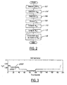
- Figure 3 shows a graph of estimated MAF using equation (31) (line 202) versus the measured MAF (line 200) over a period of 200 seconds.
- the control schemes further differ on the basis of the underlying assumptions regarding the processes in the intake manifold. Specifically, adiabatic for equations (11) - (13) and (24) - (27) and isothermic for equations (14) - (16) and (28) - (31).
- the adiabatic assumption results in higher transient accuracy, provided the temperature measurements or estimates are accurate. If the temperature measurements or estimates contain large errors, the control scheme based on the isothermic assumptions proves more accurate.
Description
- This invention relates to turbocharged compression ignition engines having exhaust gas recirculation systems and, more particularly, to methods of estimating the mass air flow into diesel engines equipped with variable geometry turbochargers (VGT) and exhaust gas recirculation (EGR) systems.
- High performance, high speed diesel engines are often equipped with turbochargers to increase power density over a wider engine operating range, and EGR systems to reduce the production of NOx emissions.
- Turbochargers use a portion of the exhaust gas energy to increase the mass of the air charge delivered to the engine combustion chambers. The larger mass of air can be burned with a larger quantity of fuel, thereby resulting in increased power and torque as compared to naturally aspirated engines.
- A typical turbocharger consists of a compressor and turbine coupled by a common shaft. The exhaust gas drives the turbine which drives the compressor which, in turn, compresses ambient air and directs it into the intake manifold. Variable geometry turbochargers (VGT) allow the intake airflow to be optimized over a range of engine speeds. This is accomplished by changing the angle of the inlet guide vanes on the turbine stator. An optimal position for the inlet guide vanes is determined from a combination of desired torque response, fuel economy, and emissions requirements.
- EGR systems are used to reduce NOx emissions by increasing the dilution fraction in the intake manifold. EGR is typically accomplished with an EGR valve that connects the intake manifold and the exhaust manifold. In the cylinders, the recirculated exhaust gas acts as an inert gas, thus lowering the flame and in-cylinder gas temperature and, hence, decreasing the formation of NOx. On the other hand, the recirculated exhaust gas displaces fresh air and reduces the air-to-fuel ratio of the in-cylinder mixture.
- Both the VGT and EGR regulate gas flow from the exhaust manifold, and their effect is, therefore, coupled through the conditions in the exhaust manifold. Excessive EGR rates displace the intake of fresh air and may lead to incomplete combustion of the injected fuel which, in turn, could cause visible levels of smoke and increased levels of emissions. Moreover, this could negatively affect fuel economy and/or performance. Thus, for effective control of diesel engines with EGR systems, it is necessary to control the EGR flow precisely, not only in steady state but also in transient conditions. In the case of diesel engines equipped with a VGT, the actual flow through the EGR valve can vary greatly, even for a fixed EGR valve opening, depending upon the exhaust pressure fluctuations generated by opening or closing the inlet guide vanes of the VGT. In such a case, it is difficult to control the EGR flow based solely on EGR valve position.
- Accordingly, current engine designs utilize a mass airflow (MAF) sensor and a manifold absolute pressure (MAP) sensor for proper regulation of airflow into the engine and, consequently, EGR flow in VGT-equipped engines. Regulation of airflow is important because it directly relates to the amount of fuel that can be injected to meet driver demand, while avoiding visible smoke and excessive particulate emissions.
- Set points for MAP and MAF are developed by engine mapping which is referenced to fuel demand as well as and engine speed. The EGR valve is used to control MAF, and the VGT is used to control MAP. Neither EGR flow nor VGT position is typically measured. Conventional MAF sensors, however, have limited accuracy and are more expensive than MAP sensors or exhaust manifold pressure (EXMP) sensors.
- According to the present invention, there is provided a method of calculating the airflow into the compressor of a turbocharged compression ignition engine having an EGR system. The method comprises the steps of generating MAP and EXMP values, determining the position of the EGR valve, and determining the exhaust gas temperature and the intake aircharge temperature. From these measured or estimated values, the EGR flow is calculated as a function of MAP and EXMP, the exhaust gas temperature value, and the position of the EGR valve. Once the EGR flow value is obtained, the compressor air flow value, i.e., MAF, is determined dynamically as a function of the EGR flow value, the intake aircharge temperature value, and dynamic estimator state. The compressor flow value is then used to control the position of the EGR valve.
- An embodiment of the invention estimates the compressor mass air flow (MAF) based on MAP and EXMP and EGR valve position rather than a MAF sensor. It improves EGR control by providing an accurate estimate of MAF.
- The invention is advantageous in that it reduces system costs by taking advantage of an EXMP sensor as a replacement for the more expensive conventional MAF sensor.
- EP 0774574 describes a system for estimating equivalent air intake amounts from values sensed by a MAF sensor.
- The invention will now be described further, by way of example, with reference to the accompanying drawings, in which:
- Figure 1 is a schematic view of a compression ignition engine system having an EGR system and a VGT in accordance with one embodiment of the present invention;
- Figure 2 is a logic diagram describing a method of estimating MAF in accordance with one embodiment of the present invention; and
- Figure 3 is a graphical representation of one embodiment of the estimation method versus the actual MAF.
-
- Turning first to Figure 1, there is shown a simplified schematic diagram of a compression
ignition engine system 10 equipped with an exhaust gas recirculation (EGR)system 12 and a variable geometry turbocharger (VGT) 14. Arepresentative engine block 16 is shown having fourcombustion chambers 18. Each of thecombustion chambers 18 includes a direct-injection fuel injector 20. The duty cycle of thefuel injectors 20 is determined by the engine control unit (ECU) 24 and transmitted alongsignal line 22. Air enters thecombustion chambers 18 through theintake manifold 26, and combustion gases are exhausted through theexhaust manifold 28 in the direction ofarrow 30. - To reduce the level of NOx emissions, the engine is equipped with an
EGR system 12. TheEGR system 12 comprises aconduit 32 connecting theexhaust manifold 28 to theintake manifold 26. This allows a portion of the exhaust gases to be circulated from theexhaust manifold 28 to theintake manifold 26 in the direction ofarrow 31. AnEGR valve 34 regulates the amount of exhaust gas recirculated from theexhaust manifold 28. In the combustion chambers, the recirculated exhaust gas acts as an inert gas, thus lowering the flame and in-cylinder gas temperature and decreasing the formation of NOx. On the other hand, the recirculated exhaust gas displaces fresh air and reduces the air-to-fuel ratio of the in-cylinder mixture. - The
turbocharger 14 uses exhaust gas energy to increase the mass of the aircharge delivered to theengine combustion chambers 18. The exhaust gas flowing in the direction ofarrow 30 drives theturbocharger 14. This larger mass of air can be burned with a larger quantity of fuel, resulting in more torque and power as compared to naturally aspirated, non-turbocharged engines. - The
turbocharger 14 consists of acompressor 36 and aturbine 38 coupled by acommon shaft 40. Theexhaust gas 30 drives theturbine 38 which drives thecompressor 36 which, in turn, compressesambient air 42 and directs it (arrow 43) into theintake manifold 26. The VGT 14 can be modified as a function of engine speed during engine operation by varying the turbine flow area and the angle at which theexhaust gas 30 is directed at the turbine blades. This is accomplished by changing the angle of theinlet guide vanes 44 on theturbine 38. The optimal position for theengine guide vanes 44 is determined from the desired engine operating characteristics at various engine speeds. - As can be appreciated from Figure 1, both the EGR 12 and the VGT 14 regulate gas flow from the
exhaust manifold 28. The effect of the EGR and VGT is, therefore, jointly dependent upon the conditions in theexhaust manifold 28. - All of the engine systems, including the EGR 12 and VGT 14, are controlled by the ECU. For example,
signal 46 from theECU 24 regulates the EGR valve position, andsignal 48 regulates the position of theVGT guide vanes 44. - In the
ECU 24, the command signals 46, 48 to theEGR 12 and VGT 14 actuators are calculated from measured variables and engine operating parameters by means of a control algorithm. Sensors and calibratable lookup tables provide the ECU 24 with engine operating information. For example,MAP sensor 50 provides asignal 52 to theECU 24 indicative of the pressure in theintake manifold 26. Likewise, EXMPsensor 54 provides anEXMP signal 56 to theECU 24 indicative of the pressure in theexhaust manifold 28. Further, anaircharge temperature sensor 58 provides asignal 60 to theECU 24 indicative of the temperature of theintake aircharge 42. Additional sensory inputs can also be received by the ECU alongsignal line 62 such as engine coolant temperature, engine speed, and throttle position. Based on the sensory inputs and engine mapping data stored in memory, the ECU controls the EGR to regulate the intake airflow (MAF), and controls the VGT to regulate the intake manifold pressure (MAP). Because thesystem 10 does not include a MAF sensor, however, MAP and EXMP are used to control the EGR. - Figure 2 describes the logic flow of the ECU to estimate the intake airflow and control the EGR valve.
- Throughout the specification, the following notations are used in describing measured or calculated variables:
- p
- pressure (kPa)
- T
- temperature (K)
- m
- mass (kg)
- W
- mass flow (kg/s)
- F
- burnt gas fraction
- αegr
- EGR valve position
- Furthermore, the following subscripts are used to denote regions of the engine system:
- 1
-
intake manifold 26 - 2
-
exhaust manifold 28 - e
-
engine block 16 - t
-
turbine 38 - c
-
compressor 36 - Finally, the following thermodynamic constants are referenced for air at 300K:
cp = 1.0144kJ/kg/K R = cp - cν cν = 0.7274 kJ/kg/K γ = cp /cν - Hence, the symbol p 1, for example, refers to the intake manifold pressure in kPa. Combined subscripts, such as "e2", refer to flows from the first to the second subsystem.
- As mentioned above, it is desirable to control the EGR based on the mass airflow into the intake manifold.
Typically, this is accomplished by monitoring the output of a MAF sensor located in upstream from the compressor. In the present invention, however, the intake mass airflow is estimated as a function of several measured and calculated variables. Figure 2 describes the logic routine to accomplish EGR control based on an estimate of intake mass airflow. This logic routine resides in the ECU and is executed as part of the foreground logic routine used to control the engine operating characteristics. - In
step 102, measurements of intake manifold pressure (p 1) and exhaust manifold pressure (p 2) are received by theECU 24 by way ofsignal inputs - Similarly, at
step 104 the EGR valve position (αegr) is determined. Atstep 106, the temperature across the EGR system (T21) is determined from a steady-state map based on engine operating conditions. Alternatively, T21 can be assumed to be a constant. The air charge temperature (Tc1) can also be measured by a temperature sensor such assensor 58 of Figure 1, or estimated based on engine operating conditions. - Step 110 calculates the EGR flow value as a function of p 1, p 2, T21, and αegr according to the following equation:
- In equation (1), f 1(αegr) represents the effective flow area of the EGR valve as a function of the position of the EGR valve, R represents the difference between the pressure specific heat constant and volume specific heat constant, and represents a standard orifice equation having the following form:
- With knowledge of the EGR flow value, W21, the compressor flow rate Wc1 can be calculated in
step 112 from the following differential equation describing the intake manifold pressure: - Hence, equation (2) can be rewritten as follows:
- Thus, from equation (5), the only unknown term is the compressor flow rate Wc1. An observer is, therefore, constructed to dynamically estimate the product Wc1Tc1 by interpreting the scaled enthalpy flow as the state of a dynamic system whose dynamics are assumed to be zero. In steady state, this is true; during transient conditions, however, the system dynamics could be approximated by a term proportional to the first derivative of the accelerator pedal position, requested fuel signal, or VGT actuator signal. Assume the state of the estimator is the scaled enthalpy flow, z = Wc1Tc1, and letting p 1 and z be estimates of intake manifold pressure and z, respectively, a pressure error term and flow error term can be defined as follows:
- The following differential equations are then observers for manifold pressure and enthalpy flow:
- From the eigenvalues of this linear system, appropriate values for the design parameters M and L can be determined; a requirement being that the eigenvalues of the error system are in the left half of the complex plane. For example, assuming M = 0.5, L = 0.5, and V1 = 0.003m3, and the engine operating conditions yielding nvol = 0.85, the eigenvalues are given by -7.3353 and -4.5647.
- The estimate of the compressor airflow value (Wc1) is then given by the following equation:
- In order to implement equation (10) in the digital ECU, it can be discretized with a sufficiently small sampling period δt. In such a case, the value of Wc1 is governed by the following equations:
- Alternatively, the compressor airflow value can be defined on the basis of the ideal gas law -- instead of the first law of thermodynamics as in equations (4) and (13) -- as follows:
- With the compressor airflow estimate from equation (13) or (16), the ECU controls the EGR valve in
step 114 in any known manner substituting the typical MAF sensor measurement by the value calculated for Wc1 in equation (13) or (16). - In accordance with another embodiment of the invention, Wc1 can be calculated by another method based on the first law of thermodynamics wherein the following equation defines the intake manifold pressure:
- Applying a Laplace transform to both sides of equation (17) and multiplying equation (17) by 1/(s/τ+1) results in the following equation:
- From equation (18) estimates for the time rate of change of the intake pressure and compressor flow rate can be defined as follows:
- Substituting these values in equation (18), the filtered intake mass airflow, Wc1 , is defined as:
- Intake pressure, p 1, and intake aircharge temperature, Tc1, are measured values from
MAP sensor 50 andtemperature sensor 58 of Figure 1. The remaining variables are either known or can be resolved. For example, the EGR mass flow, W21, is obtained from the standard orifice equation, using measured exhaust manifold pressure, intake manifold pressure, and the EGR valve position as in equation (1). Similarly, the engine intake flow rate, W1e, is obtained from the mapped volumetric efficiency, measured intake manifold pressure, and engine speed as in equation (3). Also, the temperature across the EGR system, T21, can be taken as a constant, or mapped as a function of measured engine operating conditions. Finally, the intake manifold temperature, T1, is obtained from the steady state equation: - Preferably, to implement the control logic in the digital ECU, the logic can be sampled over discrete time periods, δt, resulting in the following controller equations:
- As a further embodiment, the compressor airflow value can be defined on the basis of the ideal gas law, instead of the first law of thermodynamics as in equations (17), (26), and (27), as follows:
- The performance of the compressor flow rate method as defined by equation (31) is illustrated in Figure 3. Figure 3 shows a graph of estimated MAF using equation (31) (line 202) versus the measured MAF (line 200) over a period of 200 seconds.
- From the foregoing, it will be seen that there has been brought to the art a new and improved method of estimating intake mass airflow, Wc1, which eliminates the necessity for a MAF sensor. At least four methods of estimating Wc1 have been provided in equations (13), (16), (27) and (31). The control scheme of equations (11)-(13) and (14) - (16) are observer-based and incorporate two tuning parameters (M and L or M' and L', respectively) which can be used to optimize engine performance during transient conditions. The control schemes of equations (24)-(27) and (28)-(31) are filter-based, with tuning accomplished by adjusting the bandwidth parameter of the filter, τ. The control schemes further differ on the basis of the underlying assumptions regarding the processes in the intake manifold. Specifically, adiabatic for equations (11) - (13) and (24) - (27) and isothermic for equations (14) - (16) and (28) - (31). The adiabatic assumption results in higher transient accuracy, provided the temperature measurements or estimates are accurate. If the temperature measurements or estimates contain large errors, the control scheme based on the isothermic assumptions proves more accurate.
- While the invention has been described in connection with one or more embodiments, it will be understood that the invention is not limited to those embodiments. For example, although the engine system described includes a variable geometry turbocharger, the disclosed method would equally apply to engine systems with fixed geometry turbochargers.
Claims (9)
- A method of calculating the airflow into a compressor of a turbocharged compression ignition engine having an exhaust gas recirculation system (12) having a valve (34) connecting an intake manifold (26) and exhaust manifold (28) of the engine, the method comprising the steps of:measuring an intake pressure value (p 1) which is indicative of the intake manifold pressure;measuring an exhaust pressure value (p 2) which is indicative of the exhaust manifold pressure;determining a first value (αegr) indicative of the position of the exhaust gas recirculation valve (34);determining a first temperature value (T21) indicative of the temperature of the exhaust gas flowing through the exhaust gas recirculation system (12);measuring a second temperature value (Tc1) indicative of the temperature of the aircharge entering the intake manifold (26) of the engine;calculating an exhaust gas recirculation flow value (W21) as a function of p 1, p 2, T21, and αegr; andcalculating a compressor airflow value (Wc1) as a function of said exhaust gas recirculation flow value (W21) and said second temperature value (Tc1), said compressor airflow value being used to control the position of said exhaust gas recirculation valve (34).
- A method as claimed in claim 1, wherein the step of determining a first temperature value (T21) includes the step of retrieving said first temperature value from a table of values indexed by engine speed.
- A method as claimed in claim 1,wherein the step of determining a first temperature value (T21) includes the step of retrieving said first temperature value from a table of values indexed by engine speed, fueling rate and fuel injection timing.
- A method as claimed in claim 1, wherein the step of calculating an exhaust gas recirculation flow value (W21) is governed by the following equation:
- A method as claimed in claim 4, wherein the step of calculating compressor airflow value (Wc1) is governed by the following equation:
- A method as claimed in claim 4, wherein the step of calculating compressor airflow value (Wc1) includes the step of calculating Wc1 over discrete sampling periods δt, the value of Wc1 being governed by the following equation:
- A method as claimed in claim 4, wherein the step of calculating a compressor airflow value (Wc1) includes the step of calculating Wc1 over discrete sampling periods δt, the value of Wc1 being governed by the following equation:
- A method as claimed in claim 4, wherein the step of calculating a compressor airflow value (Wc1) includes the step of calculating Wc1 over discrete sampling periods δt, the value of Wc1 being governed by the following equation:
- A method as claimed in claim 4, wherein the step of calculating a compressor airflow value (Wc1) includes the step of calculating Wc1 over discrete sampling periods δt, the value of Wc1 being governed by the following equation:
Applications Claiming Priority (2)
| Application Number | Priority Date | Filing Date | Title |
|---|---|---|---|
| US09/236,991 US6035639A (en) | 1999-01-26 | 1999-01-26 | Method of estimating mass airflow in turbocharged engines having exhaust gas recirculation |
| US236991 | 1999-01-26 |
Publications (3)
| Publication Number | Publication Date |
|---|---|
| EP1024262A2 EP1024262A2 (en) | 2000-08-02 |
| EP1024262A3 EP1024262A3 (en) | 2000-08-30 |
| EP1024262B1 true EP1024262B1 (en) | 2003-04-23 |
Family
ID=22891871
Family Applications (1)
| Application Number | Title | Priority Date | Filing Date |
|---|---|---|---|
| EP00300287A Expired - Fee Related EP1024262B1 (en) | 1999-01-26 | 2000-01-17 | Estimated mass airflow in turbocharged engines having exhaust gas recirculation |
Country Status (3)
| Country | Link |
|---|---|
| US (1) | US6035639A (en) |
| EP (1) | EP1024262B1 (en) |
| DE (1) | DE60002238T2 (en) |
Families Citing this family (84)
| Publication number | Priority date | Publication date | Assignee | Title |
|---|---|---|---|---|
| US7281527B1 (en) * | 1996-07-17 | 2007-10-16 | Bryant Clyde C | Internal combustion engine and working cycle |
| US8215292B2 (en) | 1996-07-17 | 2012-07-10 | Bryant Clyde C | Internal combustion engine and working cycle |
| US6145313A (en) * | 1997-03-03 | 2000-11-14 | Allied Signal Inc. | Turbocharger incorporating an integral pump for exhaust gas recirculation |
| JP3430923B2 (en) * | 1998-06-15 | 2003-07-28 | 日産自動車株式会社 | Supercharging control device for internal combustion engine |
| US6128902A (en) * | 1999-01-26 | 2000-10-10 | Ford Global Technologies, Inc. | Control method and apparatus for turbocharged diesel engines having exhaust gas recirculation |
| US6178749B1 (en) * | 1999-01-26 | 2001-01-30 | Ford Motor Company | Method of reducing turbo lag in diesel engines having exhaust gas recirculation |
| DE19913792A1 (en) * | 1999-03-26 | 2000-10-05 | Daimler Chrysler Ag | Charged internal combustion engine operating process, involving overflow line being forced open at set pressure difference to return exhaust gas to charge air line |
| US6354084B1 (en) | 1999-08-20 | 2002-03-12 | Cummins Engine Company, Inc. | Exhaust gas recirculation system for a turbocharged internal combustion engine |
| ATE333579T1 (en) | 1999-12-09 | 2006-08-15 | Int Engine Intellectual Prop | CONTROL OF EXHAUST GAS RECIRCULATION AND EVENT MONITORING IN A SELF-IGNITED COMBUSTION ENGINE |
| US6470866B2 (en) * | 2000-01-05 | 2002-10-29 | Siemens Canada Limited | Diesel engine exhaust gas recirculation (EGR) system and method |
| US6360541B2 (en) * | 2000-03-03 | 2002-03-26 | Honeywell International, Inc. | Intelligent electric actuator for control of a turbocharger with an integrated exhaust gas recirculation valve |
| EP1550800B1 (en) * | 2000-03-31 | 2007-11-14 | Detroit Diesel Corporation | Method of controlling an internal combustion engine |
| US6347519B1 (en) * | 2000-03-31 | 2002-02-19 | Detroit Diesel Corporation | System and method for measuring recirculated exhaust gas flow in a compression-ignition engine |
| JP3687485B2 (en) * | 2000-05-12 | 2005-08-24 | 日産自動車株式会社 | Diesel engine control device |
| US6378515B1 (en) * | 2000-06-09 | 2002-04-30 | Mack Trucks, Inc. | Exhaust gas recirculation apparatus and method |
| US6543227B2 (en) | 2001-01-31 | 2003-04-08 | Cummins Engine Company, Inc. | Automated active variable geometry turbocharger diagnosis system |
| FR2824596B1 (en) * | 2001-05-14 | 2003-12-12 | Renault | METHOD FOR ESTIMATING AIR FLOW IN AN ENGINE AND DEVICE FOR MONITORING THE OPERATION OF SUCH AN ENGINE |
| US6708104B2 (en) | 2001-07-27 | 2004-03-16 | Detroit Diesel Corporation | Engine control based on exhaust back pressure |
| EP1715163A1 (en) * | 2001-11-28 | 2006-10-25 | Volkswagen Aktiengesellschaft | Method for determining the composition of a gas mixture in a combustion chamber of an internal combustion engine with exhaust gas recirculation |
| US6711489B2 (en) | 2001-12-05 | 2004-03-23 | Visteon Global Technologies, Inc. | Method for estimating engine cylinder variables using second order sliding modes |
| GB2388922B (en) * | 2002-01-31 | 2005-06-08 | Cambridge Consultants | Control system |
| US7347171B2 (en) * | 2002-02-04 | 2008-03-25 | Caterpillar Inc. | Engine valve actuator providing Miller cycle benefits |
| US20050247286A1 (en) * | 2002-02-04 | 2005-11-10 | Weber James R | Combustion engine including fluidically-controlled engine valve actuator |
| US6732685B2 (en) | 2002-02-04 | 2004-05-11 | Caterpillar Inc | Engine valve actuator |
| US6722349B2 (en) | 2002-02-04 | 2004-04-20 | Caterpillar Inc | Efficient internal combustion engine valve actuator |
| US6688280B2 (en) * | 2002-05-14 | 2004-02-10 | Caterpillar Inc | Air and fuel supply system for combustion engine |
| US6697729B2 (en) * | 2002-04-08 | 2004-02-24 | Cummins, Inc. | System for estimating NOx content of exhaust gas produced by an internal combustion engine |
| US6732522B2 (en) | 2002-04-08 | 2004-05-11 | Cummins, Inc. | System for estimating engine exhaust pressure |
| US20050247284A1 (en) * | 2002-05-14 | 2005-11-10 | Weber James R | Air and fuel supply system for combustion engine operating at optimum engine speed |
| US6941909B2 (en) * | 2003-06-10 | 2005-09-13 | Caterpillar Inc | System and method for actuating an engine valve |
| US20050241597A1 (en) * | 2002-05-14 | 2005-11-03 | Weber James R | Air and fuel supply system for a combustion engine |
| US20050235950A1 (en) * | 2002-05-14 | 2005-10-27 | Weber James R | Air and fuel supply system for combustion engine |
| US7004122B2 (en) * | 2002-05-14 | 2006-02-28 | Caterpillar Inc | Engine valve actuation system |
| US7069887B2 (en) | 2002-05-14 | 2006-07-04 | Caterpillar Inc. | Engine valve actuation system |
| US7191743B2 (en) * | 2002-05-14 | 2007-03-20 | Caterpillar Inc | Air and fuel supply system for a combustion engine |
| US6742335B2 (en) | 2002-07-11 | 2004-06-01 | Clean Air Power, Inc. | EGR control system and method for an internal combustion engine |
| JP3861046B2 (en) * | 2002-11-01 | 2006-12-20 | トヨタ自動車株式会社 | EGR gas flow rate estimation device for internal combustion engine |
| US6805095B2 (en) * | 2002-11-05 | 2004-10-19 | Ford Global Technologies, Llc | System and method for estimating and controlling cylinder air charge in a direct injection internal combustion engine |
| US6948475B1 (en) | 2002-11-12 | 2005-09-27 | Clean Air Power, Inc. | Optimized combustion control of an internal combustion engine equipped with exhaust gas recirculation |
| US20040144082A1 (en) * | 2003-01-29 | 2004-07-29 | Visteon Global Technologies, Inc. | Controller for controlling oxides of nitrogen (NOx) emissions from a combustion engine |
| US6912458B2 (en) * | 2003-06-25 | 2005-06-28 | Caterpillar Inc | Variable valve actuation control for operation at altitude |
| US20050039711A1 (en) * | 2003-08-18 | 2005-02-24 | Bryant Clyde C. | Internal combustion engine and working cycle |
| JP3956137B2 (en) * | 2003-09-18 | 2007-08-08 | トヨタ自動車株式会社 | Method for estimating the temperature of an air-fuel mixture in an internal combustion engine |
| US7398773B2 (en) * | 2003-11-12 | 2008-07-15 | Mack Trucks, Inc. | EGR recovery system and method |
| GB0403718D0 (en) * | 2004-02-19 | 2004-03-24 | Epicam Ltd | An engine and an apparatus for providing forced aspiration to an engine |
| FR2868128B1 (en) * | 2004-03-29 | 2007-11-23 | Renault Sas | METHOD AND SYSTEM FOR CONTROLLING THE OPERATION OF AN INTERNAL COMBUSTION ENGINE OF A MOTOR VEHICLE EQUIPPED WITH A TURBOCHARGER ASSEMBLY |
| EP1607606B1 (en) * | 2004-06-15 | 2008-04-09 | C.R.F. Società Consortile per Azioni | Method and device for determining an internal combustion engine intake air flow rate based on the measurement of the oxygen concentration in the gaseous mixture taken in by the engine |
| FR2872220B1 (en) * | 2004-06-24 | 2008-10-31 | Renault Sas | METHOD FOR CONTROLLING RECIRCULATED EXHAUST GAS FLOW IN A VEHICLE ENGINE |
| JP2006029247A (en) * | 2004-07-20 | 2006-02-02 | Denso Corp | Stop and start control device for engine |
| FR2878575B1 (en) * | 2004-11-30 | 2007-04-06 | Peugeot Citroen Automobiles Sa | METHOD FOR CONTROLLING AN INTAKE SYSTEM OF AN INTERNAL COMBUSTION ENGINE AND A MOTOR VEHICLE FOR CARRYING OUT SAID METHOD |
| DE102004061454A1 (en) * | 2004-12-17 | 2006-06-29 | Delphi Technologies, Inc., Troy | Method and device for engine control in a motor vehicle |
| DE102005015609B4 (en) * | 2005-04-05 | 2008-01-17 | Siemens Ag | Device for controlling an internal combustion engine |
| US7913675B2 (en) * | 2005-10-06 | 2011-03-29 | Caterpillar Inc. | Gaseous fuel engine charge density control system |
| US20070079598A1 (en) * | 2005-10-06 | 2007-04-12 | Bailey Brett M | Gaseous fuel engine charge density control system |
| US7296562B2 (en) * | 2006-03-30 | 2007-11-20 | Caterpiller Inc. | Control system and method for estimating turbocharger performance |
| FR2910934B1 (en) * | 2006-12-27 | 2009-01-30 | Renault Sas | ESTIMATION METHOD AND SYSTEM FOR MONITORING THE EGR RATE ON A MOTOR SUPERCURRENT BY A TURBOCHARGER AND EQUIPPED WITH TWO ADMISSION COLLECTORS AND A SWIRL COMPONENT. |
| US7814752B2 (en) * | 2007-02-28 | 2010-10-19 | Caterpillar Inc | Decoupling control strategy for interrelated air system components |
| US8151567B2 (en) * | 2007-05-29 | 2012-04-10 | Ford Global Technologies, Llc | Adaptive learning system and method of vane position for a variable geometry turbocharger |
| DE102007046146A1 (en) * | 2007-09-27 | 2009-04-02 | Daimler Ag | Method for estimating an external exhaust gas recirculation rate |
| US8986253B2 (en) | 2008-01-25 | 2015-03-24 | Tandem Diabetes Care, Inc. | Two chamber pumps and related methods |
| FR2931891B1 (en) * | 2008-05-28 | 2010-08-20 | Renault Sas | METHOD OF ESTIMATING EXHAUST GAS RECIRCULATION RATE ON A BI PLENUM ENGINE WITH TURBULENCE SHUTTER. |
| FR2931892B1 (en) * | 2008-05-28 | 2010-08-20 | Renault Sas | METHOD OF ESTIMATING EXHAUST GAS RECIRCULATION RATE ON A BI-PLENUM ENGINE WITH TURBULENCE COMPONENT |
| US8408421B2 (en) | 2008-09-16 | 2013-04-02 | Tandem Diabetes Care, Inc. | Flow regulating stopcocks and related methods |
| CA2737461A1 (en) | 2008-09-19 | 2010-03-25 | Tandem Diabetes Care, Inc. | Solute concentration measurement device and related methods |
| EP2459251B1 (en) | 2009-07-30 | 2014-03-12 | Tandem Diabetes Care, Inc. | Infusion pump system with disposable cartridge having pressure venting and pressure feedback |
| US8201442B2 (en) * | 2009-09-25 | 2012-06-19 | Cummins Inc. | System and method for estimating EGR mass flow rates |
| JP5133332B2 (en) * | 2009-12-15 | 2013-01-30 | 日立オートモティブシステムズ株式会社 | Control device for internal combustion engine |
| GB2484297A (en) * | 2010-10-05 | 2012-04-11 | Gm Global Tech Operations Inc | A combustion engine evaluation unit comprising fault detection system for engine using EGR |
| FR2965584B1 (en) * | 2010-10-05 | 2013-06-28 | Renault Sas | METHOD FOR DETERMINING A RECIRCULATED EXHAUST GAS RATE AT THE INPUT OF A CYLINDER OF AN INTERNAL COMBUSTION ENGINE AND ENGINE IMPLEMENTING SAID METHOD |
| US8857178B2 (en) * | 2011-06-28 | 2014-10-14 | Caterpillar Inc. | Nozzled turbocharger turbine and associated engine and method |
| US9140203B2 (en) | 2011-11-15 | 2015-09-22 | Cummins Inc. | Apparent plumbing volume of air intake and fresh airflow value determination |
| CN102493896A (en) * | 2011-12-14 | 2012-06-13 | 重庆长安汽车股份有限公司 | Exhaust manifold for exhaust gas recirculation (EGR) engine |
| BR102013002421B1 (en) * | 2012-01-31 | 2022-03-22 | International Engine Intellectual Property Company, Llc | Control method of a variable geometry turbocharger and method of controlling a turbocharger passage gate |
| US9180242B2 (en) | 2012-05-17 | 2015-11-10 | Tandem Diabetes Care, Inc. | Methods and devices for multiple fluid transfer |
| US9173998B2 (en) | 2013-03-14 | 2015-11-03 | Tandem Diabetes Care, Inc. | System and method for detecting occlusions in an infusion pump |
| FR3006375A1 (en) | 2013-06-03 | 2014-12-05 | Renault Sa | SYSTEM AND METHOD FOR DETERMINING THE MASS FRACTION OF FRESH GASES IN THE INTAKE MANIFOLD OF AN INTERNAL COMBUSTION ENGINE OF A MOTOR VEHICLE. |
| US9422877B2 (en) | 2013-10-11 | 2016-08-23 | General Electric Company | System and method for control of exhaust gas recirculation (EGR) utilizing process temperatures |
| DE102014201947B3 (en) * | 2014-02-04 | 2015-01-22 | Ford Global Technologies, Llc | Method and device for determining a charge air mass flow |
| DE102014013284A1 (en) * | 2014-09-12 | 2016-03-17 | Man Truck & Bus Ag | Internal combustion engine, in particular gas engine, for a vehicle, in particular for a utility vehicle |
| US9951701B2 (en) * | 2014-09-22 | 2018-04-24 | General Electric Company | Method and systems for EGR control |
| DE102016207358B4 (en) | 2016-04-29 | 2024-01-11 | Ford Global Technologies, Llc | Device and method for predicting the exhaust gas recirculation rate |
| DE102016207360A1 (en) | 2016-04-29 | 2017-11-02 | Ford Global Technologies, Llc | Method for forecasting the exhaust gas recirculation rate |
| US10330034B2 (en) | 2016-04-29 | 2019-06-25 | Ford Global Technologies, Llc | Device and method for predicting the exhaust gas recirculation rate |
| DE102017205829A1 (en) | 2017-04-05 | 2018-10-11 | Robert Bosch Gmbh | Method and apparatus for determining a gas system size in an internal combustion engine |
Citations (1)
| Publication number | Priority date | Publication date | Assignee | Title |
|---|---|---|---|---|
| DE19728352C1 (en) * | 1997-07-03 | 1998-08-20 | Daimler Benz Ag | Method to control charging of IC engine having exhaust gas turbocharger |
Family Cites Families (16)
| Publication number | Priority date | Publication date | Assignee | Title |
|---|---|---|---|---|
| JPS56167814A (en) * | 1980-05-28 | 1981-12-23 | Hitachi Ltd | Apparatus and method for controlling supercharger of internal combustion engine |
| DE3444877A1 (en) * | 1984-08-14 | 1986-04-17 | Robert Bosch Gmbh, 7000 Stuttgart | CONTROL DEVICE FOR AN INTERNAL COMBUSTION ENGINE AND METHOD FOR CONTROLLING THE GASES SUPPLIED FROM THE COMBUSTION AREAS OF A SELF-IGNITION COMBUSTION ENGINE CONSISTING OF AIR AND EXHAUST GAS RECOVERY AMOUNTS |
| US5228292A (en) * | 1990-08-16 | 1993-07-20 | Mercedes-Benz Ag | Arrangement for controlling the boost pressure in an internal-combustion engine supercharged by an exhaust-gas turbocharger of adjustable turbine geometry |
| US5273019A (en) * | 1990-11-26 | 1993-12-28 | General Motors Corporation | Apparatus with dynamic prediction of EGR in the intake manifold |
| US5123246A (en) * | 1991-01-25 | 1992-06-23 | Mack Trucks, Inc. | Continuously proportional variable geometry turbocharger system and method of control |
| US5333456A (en) * | 1992-10-01 | 1994-08-02 | Carter Automotive Company, Inc. | Engine exhaust gas recirculation control mechanism |
| EP0677651B1 (en) * | 1994-04-14 | 2003-05-14 | Honda Giken Kogyo Kabushiki Kaisha | EGR rate estimation system for internal combustion engine |
| JP3298358B2 (en) * | 1995-04-25 | 2002-07-02 | 日産自動車株式会社 | Method and apparatus for controlling compression end temperature in diesel engine |
| WO1996038660A1 (en) * | 1995-06-02 | 1996-12-05 | Mitsubishi Jidosha Kogyo Kabushiki Kaisha | Excess air factor detecting device and excess air factor controlling device for an engine |
| US5601068A (en) * | 1995-07-05 | 1997-02-11 | Nozel Engineering Co., Ltd. | Method and apparatus for controlling a diesel engine |
| US5520161A (en) * | 1995-07-17 | 1996-05-28 | Alternative Fuel Sytems Inc. | Exhaust gas recirculation system for a compression ignition engine and a method of controlling exhaust gas recirculation in a compression ignition engine |
| IT1284345B1 (en) * | 1996-01-26 | 1998-05-18 | Fiat Ricerche | BOOST PRESSURE CONTROL METHOD AND UNIT FOR A TURBODIESEL ENGINE WITH VARIABLE GEOMETRY TURBINE |
| DE19607071C2 (en) * | 1996-02-24 | 1997-12-18 | Bosch Gmbh Robert | Method and device for controlling an internal combustion engine |
| DE19615545C1 (en) * | 1996-04-19 | 1997-06-12 | Daimler Benz Ag | Motor vehicle diesel engine regulation device |
| JP3551675B2 (en) * | 1997-01-21 | 2004-08-11 | 日産自動車株式会社 | EGR control device for internal combustion engine |
| DE19756619B4 (en) * | 1997-04-01 | 2007-03-15 | Robert Bosch Gmbh | System for operating an internal combustion engine, in particular for a motor vehicle |
-
1999
- 1999-01-26 US US09/236,991 patent/US6035639A/en not_active Expired - Fee Related
-
2000
- 2000-01-17 EP EP00300287A patent/EP1024262B1/en not_active Expired - Fee Related
- 2000-01-17 DE DE60002238T patent/DE60002238T2/en not_active Expired - Fee Related
Patent Citations (1)
| Publication number | Priority date | Publication date | Assignee | Title |
|---|---|---|---|---|
| DE19728352C1 (en) * | 1997-07-03 | 1998-08-20 | Daimler Benz Ag | Method to control charging of IC engine having exhaust gas turbocharger |
Also Published As
| Publication number | Publication date |
|---|---|
| DE60002238T2 (en) | 2003-11-06 |
| EP1024262A3 (en) | 2000-08-30 |
| US6035639A (en) | 2000-03-14 |
| EP1024262A2 (en) | 2000-08-02 |
| DE60002238D1 (en) | 2003-05-28 |
Similar Documents
| Publication | Publication Date | Title |
|---|---|---|
| EP1024262B1 (en) | Estimated mass airflow in turbocharged engines having exhaust gas recirculation | |
| EP1024272B1 (en) | Control method for turbocharged diesel engines having exhaust gas recirculation | |
| EP1024275B1 (en) | Fuel limiting method in diesel engines having exhaust gas recirculation | |
| EP1024260B1 (en) | Control method for a variable geometry turbocharger in a diesel engine having exhaust gas recirculation | |
| EP1024263B1 (en) | Control method for turbocharged diesel engines having exhaust gas recirculation | |
| EP1024264B1 (en) | Coordinated control method for turbocharged diesel engines having exhaust gas recirculation | |
| US7100375B2 (en) | System for limiting rotational speed of a turbocharger | |
| US7089738B1 (en) | System for controlling turbocharger compressor surge | |
| US5738126A (en) | Apparatus for controlling a diesel engine with exhaust | |
| US8387593B2 (en) | EGR flow rate control apparatus of internal combustion engine | |
| EP1227233A1 (en) | A method and system for engine air-charge estimation | |
| JP4706134B2 (en) | Control device for internal combustion engine | |
| US7805940B2 (en) | Method and device for the control and diagnosis of an exhaust gas turbocharger | |
| US20050139193A1 (en) | Control device for internal combustion engine | |
| EP1358399B1 (en) | A device and a method for controlling the fuel-air ratio | |
| US6390081B1 (en) | Method and device for determining temperature values in a combustion engine | |
| US5381775A (en) | System for controlling an internal combustion engine | |
| WO2001075287A1 (en) | System and method for measuring recirculated exhaust gas flow in a compression-ignition engine | |
| GB2395297A (en) | Method for controlling cylinder air charge in a direct injection engine | |
| CA2048085A1 (en) | Method and apparatus for inferring barometric pressure surrounding an internal combustion engine | |
| US6009862A (en) | Exhaust gas recirculation control system and method | |
| US20030075158A1 (en) | Method and device for a mass flow determination via a control valve and for determining a modeled induction pipe pressure | |
| US6397820B1 (en) | Method and device for controlling a combustion engine | |
| JP3966243B2 (en) | Internal combustion engine | |
| JP3551706B2 (en) | Engine intake control device |
Legal Events
| Date | Code | Title | Description |
|---|---|---|---|
| PUAI | Public reference made under article 153(3) epc to a published international application that has entered the european phase |
Free format text: ORIGINAL CODE: 0009012 |
|
| PUAL | Search report despatched |
Free format text: ORIGINAL CODE: 0009013 |
|
| AK | Designated contracting states |
Kind code of ref document: A2 Designated state(s): DE FR GB |
|
| AX | Request for extension of the european patent |
Free format text: AL;LT;LV;MK;RO;SI |
|
| AK | Designated contracting states |
Kind code of ref document: A3 Designated state(s): AT BE CH CY DE DK ES FI FR GB GR IE IT LI LU MC NL PT SE |
|
| AX | Request for extension of the european patent |
Free format text: AL;LT;LV;MK;RO;SI |
|
| RIC1 | Information provided on ipc code assigned before grant |
Free format text: 7F 02B 37/24 A, 7F 02D 21/08 B, 7F 02D 35/00 B, 7F 02D 33/02 B |
|
| 17P | Request for examination filed |
Effective date: 20010116 |
|
| 17Q | First examination report despatched |
Effective date: 20010323 |
|
| AKX | Designation fees paid |
Free format text: DE FR GB |
|
| GRAH | Despatch of communication of intention to grant a patent |
Free format text: ORIGINAL CODE: EPIDOS IGRA |
|
| GRAH | Despatch of communication of intention to grant a patent |
Free format text: ORIGINAL CODE: EPIDOS IGRA |
|
| GRAA | (expected) grant |
Free format text: ORIGINAL CODE: 0009210 |
|
| AK | Designated contracting states |
Designated state(s): DE FR GB |
|
| PG25 | Lapsed in a contracting state [announced via postgrant information from national office to epo] |
Ref country code: FR Free format text: LAPSE BECAUSE OF FAILURE TO SUBMIT A TRANSLATION OF THE DESCRIPTION OR TO PAY THE FEE WITHIN THE PRESCRIBED TIME-LIMIT Effective date: 20030423 |
|
| REG | Reference to a national code |
Ref country code: GB Ref legal event code: FG4D |
|
| REF | Corresponds to: |
Ref document number: 60002238 Country of ref document: DE Date of ref document: 20030528 Kind code of ref document: P |
|
| PG25 | Lapsed in a contracting state [announced via postgrant information from national office to epo] |
Ref country code: GB Free format text: LAPSE BECAUSE OF NON-PAYMENT OF DUE FEES Effective date: 20040117 |
|
| PGFP | Annual fee paid to national office [announced via postgrant information from national office to epo] |
Ref country code: DE Payment date: 20040130 Year of fee payment: 5 |
|
| PLBE | No opposition filed within time limit |
Free format text: ORIGINAL CODE: 0009261 |
|
| STAA | Information on the status of an ep patent application or granted ep patent |
Free format text: STATUS: NO OPPOSITION FILED WITHIN TIME LIMIT |
|
| 26N | No opposition filed |
Effective date: 20040126 |
|
| EN | Fr: translation not filed | ||
| GBPC | Gb: european patent ceased through non-payment of renewal fee |
Effective date: 20040117 |
|
| PG25 | Lapsed in a contracting state [announced via postgrant information from national office to epo] |
Ref country code: DE Free format text: LAPSE BECAUSE OF NON-PAYMENT OF DUE FEES Effective date: 20050802 |