EP1021009B1 - Synchronisation of a network element in a synchronous digital communication network - Google Patents
Synchronisation of a network element in a synchronous digital communication network Download PDFInfo
- Publication number
- EP1021009B1 EP1021009B1 EP00440009A EP00440009A EP1021009B1 EP 1021009 B1 EP1021009 B1 EP 1021009B1 EP 00440009 A EP00440009 A EP 00440009A EP 00440009 A EP00440009 A EP 00440009A EP 1021009 B1 EP1021009 B1 EP 1021009B1
- Authority
- EP
- European Patent Office
- Prior art keywords
- network
- clock
- node
- stm
- network element
- Prior art date
- Legal status (The legal status is an assumption and is not a legal conclusion. Google has not performed a legal analysis and makes no representation as to the accuracy of the status listed.)
- Expired - Lifetime
Links
Images

Classifications
-
- H—ELECTRICITY
- H04—ELECTRIC COMMUNICATION TECHNIQUE
- H04J—MULTIPLEX COMMUNICATION
- H04J3/00—Time-division multiplex systems
- H04J3/02—Details
- H04J3/06—Synchronising arrangements
- H04J3/0635—Clock or time synchronisation in a network
- H04J3/0638—Clock or time synchronisation among nodes; Internode synchronisation
- H04J3/0641—Change of the master or reference, e.g. take-over or failure of the master
-
- H—ELECTRICITY
- H04—ELECTRIC COMMUNICATION TECHNIQUE
- H04J—MULTIPLEX COMMUNICATION
- H04J3/00—Time-division multiplex systems
- H04J3/02—Details
- H04J3/06—Synchronising arrangements
- H04J3/0635—Clock or time synchronisation in a network
- H04J3/0679—Clock or time synchronisation in a network by determining clock distribution path in a network
Definitions
- the invention relates to a method for the synchronization of network elements in a synchronous digital communication network after the The preamble of claim 1, a network element for a synchronous digital Communication network according to the preamble of claim 6 and A network management device according to claim 7.
- the network elements of a synchronous digital communications network work according to the recommendations of the ITU-T for synchronous digital hierarchy (NET) or Synchronous Optical Network (SONET). Under network elements become add / drop multiplexers, crossconnects or line multiplexers Understood. In the news broadcast in such a It is essential for all telecommunications networks Network elements work synchronously with each other. This is done by a mutual synchronization of the network elements or by master / slave synchronization achieved by each network element of a received Message signal derives a clock signal and its internal clock generator synchronized to this external clock signal. For clock supply of a highly accurate reference clock in the network serve one or more primary Reference detectors.
- a synchronization status message was introduced as part of the Message signal is transmitted.
- the SSM gives the quality of Reference clock to which the sending network element is synchronized.
- the Selecting a clock reference is done using the SSM, adding a network element always selects the message signal as a clock reference whose SSM is the highest Indicates clock quality.
- There was also the message "DNU" (do not use for synchronization ") is set as SSM in the return direction to the Network element to be sent, the message signal as a clock reference was selected.
- European Patent Application EP 0 849 904 proposes another way to avoid clock loops:
- the selection of a reference clock should be in a central clock generator of a network node to be made.
- the selected clock source becomes a central network management device then all the network elements of the node that have their reference clock received from the central clock generator of the node instructed which SSM has to send each network element to which of its outputs.
- This procedure is however consuming, since the network management device each network element for each of its outputs must explicitly assign an SSM to be sent. Also In this case it is essential to the correct configuration of the network.
- several clock interfaces with means for transmitting a SSM between clock generator and network elements are provided. This is also technically complicated and not currently available network elements intended.
- the object of the invention is to provide a method for synchronizing a Specify network element, in which the risk of formation of clock loops is reduced in particular in parallel transmission paths, but which gets by with simple technical means.
- Other objects of the invention It consists of a network element and a network management device which are suitable for carrying out the method.
- a basic idea of the invention is the selection of a clock reference not from a network element or from a central clock generator but from a central network management facility.
- the already existing network management device are all Information about the structure and configuration of the network is stored.
- Another basic idea is that a network element, if it Need for a new selection finds that Network management device for all received at its inputs Message signals contained therein Synchronization status messages transmits and the Network management device then based on the transmitted Synchronization status messages and based on the stored Information about the structure and configuration of the network one of received message signals selects as a new clock reference and the Network element communicates this selection.
- the invention is based but on the knowledge that there is no significant impairment of the Message transmission in the communications network results when after a loss or disturbance of its reference clock source Network element is not resynchronized immediately.
- switches a network element in this case to the free, unsynchronized operation around - the so-called holdover mode - and wait for the network switcher to make a new selection gets notified. Delays up to a few minutes through the Information transfer via the Q interface as well as waiting and Processing times in the network management device are for operation of the network uncritical.
- a network element may be after the loss of its reference clock source even as usual in the art even a new referent clock source choose. However, this selection is then temporary to the time span to be bridged by the network management facility a new Reference clock source was selected. After notification of a new one Reference clock source through the network management device switches that Network element to the communicated to.
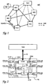
- a synchronous digital communication network NET which according to the Recommendations for Synchronous Digital Hierarchy (SDH) is shown in Figure 1 shown. It consists of a series of subunits by optical or electrical transmission media LINK bidirectionally connected network elements NE1 -NE5 and from a central network management device TMN.
- the Network management facility TMN serves to provide logical connections between the network elements, error messages and alarms too monitor and configure the network NET.
- she has after the inventive method the task of each network element a Assign reference clock source.
- Such a network management device is also often referred to as network management.
- a highly accurate Reference clock REF is at the network element NE1 of a primary Reference clock generator (primary reference clock) PRC fed into the grid.
- the synchronization is done by for each network element, a received message signal as Is selected, the network element of the selected Message signal derives a clock signal and its internal clock generator tunes with this clock signal. If a connection falls between two Network elements due to a defect, so can a resynchronization be required. This will change the network elements involved received message signal selected as a new clock reference.
- the selection of a reference clock source takes place on the basis of synchronous transport modules contained and co-transmitted synchronization status messages SSM, each indicating the clock quality of the sending network element.
- SSM synchronous transport modules contained and co-transmitted synchronization status messages SSM, each indicating the clock quality of the sending network element.
- the messages listed in Table 1 are defined for the SSM.
- one network element selects another using the SSM as the reference clock source out, it must send in the return direction the SSM DNU "to the selected network element to inform that the Message signals in the return direction is not also used as a clock reference may be, otherwise a clock loop would be formed.
- bundles BUNDLE of parallel transmission paths as in the Figure is shown between the network elements NE2 and NE3, on both Connections the SSM DNU "could be sent also be formed over several network elements, the annular interconnected, e.g. the network elements NE2, NE3, NE4, NE5 in the drawing. The formation of clock loops in such Configuration can not be avoided by using the SSM alone become.
- the selection of a reference clock source for each network element is made in the network management device TMN and this has all the necessary information about the configuration the network has, taking into account each received SSM and the information about the network configuration the formation of Clock loops during synchronization or resynchronization of a Network element can be effectively avoided after a failure.
- the information about the selected reference clock sources of the individual network elements in the selection considered.
- FIG. 2 shows an exemplary embodiment of a network element according to the invention shown.
- a network element NE has m inputs, which each have a Message signal STM-N1 to STM-Nm receives.
- About a Q-interface Q is the Network element with a central network management device TMN in Connection.
- the network item NE only the shown for synchronization important facilities and connections.
- the network element NE has at the m inputs each interface circuit IN1 -INm on. In each interface circuit is received from the Message signal each derived a clock signal CLK1 -CLKm. The Clock signals CLK1-CLKm are connected via appropriate connections Selector SEL supplied.
- Synchronization status messages SSM1 -SSMm which are in one Header area (overhead) of the synchronous transport modules STM-N1 to STM Nm are read and sent to a connection device COM directed.
- the connection device COM is connected via the Q interface Q the network management device TMN in conjunction.
- the network management device TMN evaluates the Synchronization status messages and selects from the Synchronization status messages and based on saved Information about the configuration of the communications network one of the derived clock signals CLK1-CLKm as a clock reference. These Selection tells the network element NE about the Q interface to the Connection device COM with.
- the connection device COM forwards the Message to the selector SEL further, which then the Selects selected clock signal to an internal TaktgeneratorPLL. at the connection device COM may be e.g. to the Control device of the network element, the so-called network element manager act.
- the internal clock generator PLL can, for example, a digital Be in phase locked loop operating in unsynchronized operation Clock signal generated with the specified in ITU-T G.812 clock quality. Is from the Selector SEL a clock signal to the internal clock generator PLL turned on, the clock signal synchronizes the clock generator PLL.
- One Output iCLK of the clock generator PLL is used as an internal reference clock all output circuits O1-Ok distributed. Message signals to be sent As a result, tSTM-N are generated with the internal reference clock iCLK and Posted.
- clock extraction circuits are in at least some the interface circuits IN1-INm of the network element NE, so that of the message signals received at these interface circuits STMN1-STMNm are respectively derived clock signals CLK1-CLKm. From these clock signals is then corresponding to the selector SEL the selection of the network management device TMN as a reference clock selected. Alternatively, however, only a clock derivation circuit be provided, which of the currently selected message signal the Derives reference clock signal.
- the network management facility shares the network element NE via the Q interface Q and the Connection device COM also one to be sent Synchronization status message tSSM for each output O1-OK with.
- This allows the use of the SSM DNU "(Do Not Use for Synchronization ") in all directions to the selected reference clock source, so that network elements that are not according to the invention Synchronization method work, but based on the SSM itself one Selection, also operated in the communications network can be.
- the network element NE can also, as is known from the Standardization is provided, the SSM of the selected as a clock reference received message signal, because the formation of Clock loops are caused by the network management device TMN the consideration of the information stored there about construction and Configuration of the communication network avoided.
- the inventive method of the embodiment is shown as a flowchart in Figure 3.
- the method is performed when a network element is to be synchronized or when a network element has lost its previous reference clock source due to a disturbance and is to be re-synchronized.
- the procedure includes the following steps: Step S1 Several message signals are received at the network element to be synchronized. One of these message signals should be used as a new clock reference. All received message signals contain a synchronization status message.
- Step S2 The synchronization status messages of the individual received message signals are read by the network element.
- Step S3 The network element transmits the read synchronization status messages to the central network management device together with information from which message signal the respective synchronization status message originated or at which input the relevant message signal was received.
- Step S4 The network management device uses the synchronization status messages to select the information received about the origin of the respective synchronization status message and based on the stored information about the structure and configuration of the communication network of the message signals as a new clock reference.
- Step S5 The network management device notifies the network element of the choice made.
- Step S6 The network element derives a clock signal from the selected message signal.
- Step S7 With the clock signal derived from the selected message signal, it equalizes its internal clock generator to synchronize to the new reference clock source.
- the network management device shown in FIG. 4 has means for Receive the transmitted from a network element Synchronization status messages, means for storing information on the structure and configuration of the communications network and means of selection a clock reference for a network element based on the transmitted Synchronization status messages and based on saved Information.
- the network management device contains a Q interface circuit I / O with that for messaging networks specified Q interface Q is connected, a semiconductor memory MEM for buffering a selection request of a network element and intermediate results of the selection algorithm, a data store with a database DATA, for example in the form of a hard disk Processor CPU, which performs the selection by means of a control program, and a bus system, which Q interface circuit I / O, semiconductor memory MEM, data memory DATA and processor CPU connects.
- the in the Datastore contained database contains all information about construction and configuration of the communications network.
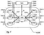
- the invention is applicable to the selection of a Reference clock source for a network node NODE, which has multiple network elements NE1 -NE6 and a central node clock generator SASE.
- the network node NODE contains six network elements NE1-NE6 and the central one Nodal generator SASE.
- the node clock generator SASE can be used as both separate device be placed in the node as well as in one of Network elements, preferably a crossconnect to be integrated.
- Each of the Network elements NE1 -NE6 sends in from a received Message signal STM-N derived clock signal CLK1-CLK6 to the Nodal generator SASE.
- the node clock generator synchronizes to one of these clock signals and sends a common reference clock signal REF back to all network elements.
- the network elements NE1-NE6 synchronize in turn to the received from the node clock generator SASE Reference clock signal REF.
- the network node NODE is connected to a central Network management device TMN in conjunction. And that is both each of the network elements with the network management device TMN connected as well as the central node clock generator SASE.
- the network elements send to the network management device TMN the Synchronization status message SSM1-SSM6 received in the Message signal is included, from which the respective to the Node clock generator SASE forwarded clock signal CLK1-CLK6 is derived.
- Based on the notified synchronization status messages SSM1-SSM6 and based on data stored in the network management device TMN about structure and configuration of the communication network chooses the Network management device TMN one of the clock signals CLK1-CLK6 than Reference clock source for the network node NODE off.
- the selection divides the Network Manager TMN the central node clock generator SASE via the Q interface Q with.
- the node clock generator SASE then synchronizes to the selected clock signal.
- the network management device TMN shares the individual network elements NE1-NE6 also due to the quality of the selected clock reference with which synchronization status message they send at their outputs should (see Table 1).
- Synchronization status messages SSM1-SSM6 can also do that anyway between network elements and the network management device TMN existing Q interface can be used.
- the network elements NE1-NE6 preferably provide add / drop multiplexers and a crossconnect.
- the network node may be the one in a Switch set up synchronous digital network elements Messaging network act over which the exchange its Long-distance traffic handles.
- the node clock generator is preferably in the Integrated crossconnect and is also used as an internal clock generator of the Used crossconnects.
- the node clock generator SASE is for the Clock processing and clock distribution of the uniform reference clock signal REF of the network node NODE. He stands like the network elements with the Network management device TMN via the Q interface in conjunction.
- the node clock generator SASE is designed as a stand-alone device, he may also be considered as a network element in the context of the invention, the input signals of which are the same as those of the other network elements of the Node's received clock signals CLK1-CLK6.
- the clock signals These can be 2 MHz signals or 2 MBit signals which the synchronization status message also to the node clock generator can be transferred.
- one or more of the network elements NE1-NE6 the clock signal CLK1-CLK6, which this to the node clock generator SASE send, switch off, e.g. when a fault occurs. This function is called Squelch is called. If this is the clock signal, on which the node clock generator synchronizes, then there is the Need to make a new selection.
- the node clock generator sets determines that the input signal to which it is synchronizing has failed and notifies the network manager TMN that a new one Selection is required.
- the network management device TMN then performs according to the method of the invention, the selection by and divides the Node clock generator SASE the new selection via the Q-interface Q with. In the meantime, the node clock generator switches to unsynchronized Operation (so-called holdover mode).
Landscapes
- Engineering & Computer Science (AREA)
- Computer Networks & Wireless Communication (AREA)
- Signal Processing (AREA)
- Synchronisation In Digital Transmission Systems (AREA)
- Data Exchanges In Wide-Area Networks (AREA)
- Time-Division Multiplex Systems (AREA)
- Mobile Radio Communication Systems (AREA)
- Telephonic Communication Services (AREA)
Abstract
Description
Die Erfindung betrifft ein Verfahren zur Synchronisation von Netzelementen in einem synchronen digitalen Nachrichtenübertragungsnetz nach dem Oberbegriff des Anspruchs 1, ein Netzelement für ein synchrones digitales Nachrichtenübertragungsnetz nach dem Oberbegriff des Anspruchs 6 und eine Netzwerkverwaltungseinrichtung nach Anspruch 7.The invention relates to a method for the synchronization of network elements in a synchronous digital communication network after the The preamble of claim 1, a network element for a synchronous digital Communication network according to the preamble of claim 6 and A network management device according to claim 7.
Die Netzelemente eines synchronen digitalen Nachrichtenübertragungsnetzes arbeiten nach den Empfehlungen der ITU-T für synchrone digitale Hierarchie (NET) oder Synchronous Optical Network (SONET). Unter Netzelementen werden Add/Drop-Multiplexer, Crossconnects oder Leitungsmultiplexer verstanden. Bei der Nachrichtenübertragung in einem solchen Nachrichtenübertragungsnetz kommt es wesentlich darauf an, daß alle Netzelemente synchron miteinander arbeiten. Dies wird durch eine gegenseitige Synchronisation der Netzelemente oder durch Master/Slave-Synchronisation erreicht, indem jedes Netzelement von einem empfangenen Nachrichtensignal ein Taktsignal ableitet und seinen internen Taktgenerator auf dieses externe Taktsignal synchronisiert. Zur Takteinspeisung eines hochgenauen Referenztaktes in das Netz dienen ein oder mehrere primäre Referenzta ktgeneratoren. The network elements of a synchronous digital communications network work according to the recommendations of the ITU-T for synchronous digital hierarchy (NET) or Synchronous Optical Network (SONET). Under network elements become add / drop multiplexers, crossconnects or line multiplexers Understood. In the news broadcast in such a It is essential for all telecommunications networks Network elements work synchronously with each other. This is done by a mutual synchronization of the network elements or by master / slave synchronization achieved by each network element of a received Message signal derives a clock signal and its internal clock generator synchronized to this external clock signal. For clock supply of a highly accurate reference clock in the network serve one or more primary Reference detectors.
Um die Auswahl eines Nachrichtensignals als Taktreferenz zu verbessern wurde eine Synchronisationsstatusmeldung (SSM) eingeführt, die als Teil des Nachrichtensignals mitübertragen wird. Die SSM gibt die Qualität des Referenztaktes an, auf den das sendende Netzelement synchronisiert ist. Die Auswahl einer Taktreferenz geschieht anhand der SSM, indem ein Netzelement stets das Nachrichtensignal als Taktreferenz auswählt, dessen SSM die höchste Taktqualität anzeigt. Es wurde auch die Nachricht ,DNU" (do not use for synchronization") als SSM festgelegt, die in die Rückrichtung zu dem Netzelement gesendet werden soll, dessen Nachrichtensignal als Taktreferenz ausgewählt wurde.To improve the selection of a message signal as a clock reference A synchronization status message (SSM) was introduced as part of the Message signal is transmitted. The SSM gives the quality of Reference clock to which the sending network element is synchronized. The Selecting a clock reference is done using the SSM, adding a network element always selects the message signal as a clock reference whose SSM is the highest Indicates clock quality. There was also the message "DNU" (do not use for synchronization ") is set as SSM in the return direction to the Network element to be sent, the message signal as a clock reference was selected.
Bei der Synchronisation muß strikt darauf geachtet werden, daß keine Taktschleifen gebildet werden, d.h. daß nicht zwei Netzelemente sich gegenseitig als Synchronisationstaktquelle auswählen. Die Gefahr der Bildung von Taktschleifen ist besonders dann gegeben, wenn zwischen zwei Netzelementen mehrere parallele Übertragungswege vorhanden sind. Solche parallelen Übertragungswege werden auch als Bündel bezeichnet. Durch die Verwendung der SSM DNU" allein kann nicht in allen möglichen Situationen die Bildung von Taktschleifen vermieden werden.In the synchronization must be strictly taken to ensure that no Clock loops are formed, i. that not two network elements themselves select each other as the synchronization clock source. The danger of education of cycle loops is especially given when between two Network elements multiple parallel transmission paths are available. Such parallel transmission paths are also called bundles. By the Using the SSM DNU "alone can not be done in all sorts of situations the formation of clock loops can be avoided.
In der Europäischen Patentanmeldung EP 0 723 344 wird vorgeschlagen, zur Vermeidung von Taktschleifen zwei Klassen von Schnittstelleneinrichtungen zu definieren, wobei nur Nachrichtensignale, die an einer Schnittstelleneinrichtung der ersten Klasse empfangen werden als Taktreferenz ausgewählt werden dürfen, jedoch Nachrichtensignale, die an Schnittstelleneinrichtungen der zweiten Klasse empfangen werden, bei der Auswahl eines Referenztaktes zu ignorieren sind. Durch geeignete Konfiguration des Netzes, indem beispielsweise nur Schnittstellen der ersten Klasse mit Schnittstellen der zweiten Klasse verbunden werden, lassen sich Taktschleifen vermeiden. Diese Lösung ist jedoch fehleranfällig, da es auf die richtige Konfiguration des Netzes ankommt. Insbesondere bei Bündeln paralleler Übertragungswege können sich leicht Fehler in die Konfiguration einschleichen, die dann zur Bildung von Synchronisationsschleifen führen. In the European patent application EP 0 723 344 it is proposed to Avoiding clock loops two classes of interface devices too define only message signals that are sent to a Interface means of the first class are received as a clock reference may be selected, however, message signals to the Interface devices of the second class are received, in the Selection of a reference clock are to be ignored. By suitable Configuration of the network by, for example, only interfaces the first Class can be connected to interfaces of the second class, can be Avoid clock loops. This solution, however, is error prone as it affects the correct configuration of the network arrives. Especially with bundles Parallel transmission paths can easily error in the configuration creep in, which then lead to the formation of synchronization loops.
Die Europäische Patentanmeldung EP 0 849 904 schlägt einen anderen Weg zur Vermeidung von Taktschleifen vor: Die Auswahl eines Referenztaktes soll in einem zentralen Taktgenerator eines Netzknotens vorgenommen werden. Die ausgewählte Taktquelle wird einer zentralen Netzwerkverwaltungseinrichtung mitgeteilt, die daraufhin alle Netzelemente des Knotens, die ihren Referenztakt von dem zentralen Taktgenerator des Knotens empfangen, instruiert, welche SSM jedes Netzelement an welchem seiner Ausgänge zu senden hat. Dadurch läßt sich erreichen, daß an allen Ausgängen, bei denen die Gefahr einer Taktschleifenbildung besteht, die SSM DNU" gesendet werden kann, wodurch die Bildung Taktschleifen wirksam verhindert wird. Dieses Verfahren ist jedoch aufwendig, da die Netzwerkverwaltungseinrichtung jedem Netzelement für jeden seiner Ausgänge explizit eine zu sendende SSM zuweisen muß. Auch hierbei kommt es wesentlich auf die richtige Konfiguration des Netzes an. Zudem müssen mehrere Taktschnittstellen mit Mitteln zum Übertragen einer SSM zwischen Taktgenerator und Netzelementen vorgesehen werden. Dies ist technisch ebenfalls aufwendig und bei derzeit erhältlichen Netzelementen nicht vorgesehen.European Patent Application EP 0 849 904 proposes another way to avoid clock loops: The selection of a reference clock should be in a central clock generator of a network node to be made. The selected clock source becomes a central network management device then all the network elements of the node that have their reference clock received from the central clock generator of the node instructed which SSM has to send each network element to which of its outputs. Thereby can be achieved that at all exits, where the danger of Clock looping exists, which can be sent to the SSM DNU the formation of clock loops is effectively prevented. This procedure is however consuming, since the network management device each network element for each of its outputs must explicitly assign an SSM to be sent. Also In this case it is essential to the correct configuration of the network. In addition, several clock interfaces with means for transmitting a SSM between clock generator and network elements are provided. This is also technically complicated and not currently available network elements intended.
Aufgabe der Erfindung ist es, ein Verfahren zur Synchronisation eines Netzelementes anzugeben, bei dem die Gefahr der Bildung von Taktschleifen insbesondere bei parallelen Übertragungspfaden vermindert ist, welches aber mit einfachen technischen Mitteln auskommt. Weitere Aufgaben der Erfindung bestehen darin, ein Netzelement und eine Netzwerkverwaltungseinrichtung anzugeben, die zur Durchführung des Verfahrens geeignet sind.The object of the invention is to provide a method for synchronizing a Specify network element, in which the risk of formation of clock loops is reduced in particular in parallel transmission paths, but which gets by with simple technical means. Other objects of the invention It consists of a network element and a network management device which are suitable for carrying out the method.
Die Aufgabe wird hinsichtlich des Verfahrens gelöst durch die Merkmale des Anspruchs 1, hinsichtlich des Netzelementes durch die Merkmale des Anspruchs 6 und hinsichtlich der Netzwerkverwaltungseinrichtung durch die Merkmale des Anspruchs 7. Vorteilhafte Ausgestaltungen sind den abhängigen Ansprüchen zu entnehmen.The object is achieved with regard to the method by the features of Claim 1, with regard to the network element by the features of Claim 6 and in terms of the network management device by the Features of claim 7. Advantageous embodiments are the refer to dependent claims.
Im folgenden wird die Erfindung anhand der Figuren 1-5 in zwei Ausführungsbeispielen beschrieben. Es zeigt:
- Figur 1:
- Ein synchrones digitales Nachrichtenübertragunsgnetz,
- Figur 2:
- ein Blockdiagramm eines erfindungsgemäßen Netzelementes und einer Netzwerkverwaltungseinrichtung,
- Figur 3:
- ein Flußdiagramm des erfindungsgemäßen Verfahrens,
- Figur 4:
- ein Blockdiagramm der erfindungsgemäßen Netzwerverwaltungseinrichtung und
- Figur 5:
- ein Blockdiagramm eines Netzknotens.
- FIG. 1:
- A synchronous digital messaging service,
- FIG. 2:
- a block diagram of a network element according to the invention and a network management device,
- FIG. 3:
- a flow chart of the method according to the invention,
- FIG. 4:
- a block diagram of the network management device according to the invention and
- FIG. 5:
- a block diagram of a network node.
Eine Grundidee der Erfindung besteht darin, die Auswahl einer Taktreferenz nicht von einem Netzelement oder von einem zentralen Taktgenerator durchzuführen, sondern von einer zentralen Netzwerkverwaltungseinrichtung. In der ohnehin vorhandenen Netzwerkverwaltungseinrichtung sind alle Informationen über den Aufbau und die Konfiguration des Netzes gespeichert. Eine weitere Grundidee besteht nun darin, daß ein Netzelement, wenn es die Notwendigkeit für eine neue Auswahl feststellt, der Netzwerkverwaltungseinrichtung für alle an seinen Eingängen empfangenen Nachrichtensignale die darin jeweils enthaltenen Synchronisationsstatusmeldungen überträgt und die Netzwerkverwaltungseinrichtung dann anhand der übertragenen Synchronisationsstatusmeldungen und anhand der gespeicherten Informationen über den Aufbau und die Konfiguration des Netzes eines der empfangenen Nachrichtensignale als neue Taktreferenz auswählt und dem Netzelement diese Auswahl mitteilt.A basic idea of the invention is the selection of a clock reference not from a network element or from a central clock generator but from a central network management facility. In the already existing network management device are all Information about the structure and configuration of the network is stored. Another basic idea is that a network element, if it Need for a new selection finds that Network management device for all received at its inputs Message signals contained therein Synchronization status messages transmits and the Network management device then based on the transmitted Synchronization status messages and based on the stored Information about the structure and configuration of the network one of received message signals selects as a new clock reference and the Network element communicates this selection.
Bekanntermaßen kann die Informationsübertragung zwischen Netzelementen und der zentralen Netzwerkverwaltungseinrichtung über die vorhandenen Q-Schnittstellen einige Sekunden bis Minuten betragen. Die Erfindung basiert aber auf der Erkenntnis, daß es zu keiner wesentliche Beeinträchtigung der Nachrichtenübertragung in dem Nachrichtenübertragungsnetz führt, wenn nach einem Verlust oder einer Störung seiner Referenztaktquelle ein Netzelement nicht umgehend neu synchronisiert wird. Entsprechend der Erfindung schaltet ein Netzelement in diesem Fall auf den freien, unsynchronisierten Betrieb um - den sogenannten Holdover-Modus - und wartet bis es von der Netzkwerksteuerungseinrichtung eine neue Auswahl mitgeteilt bekommt. Verzögerungen bis zu einigen Minuten durch die Informationsübertragung über die Q-Schnittstelle sowie Warte- und Bearbeitungszeiten in der Netzwerkverwaltungseinrichtung sind für den Betrieb des Netzes unkritisch.As is known, the transmission of information between network elements and the central network management facility over the existing ones Q interfaces for a few seconds to minutes. The invention is based but on the knowledge that there is no significant impairment of the Message transmission in the communications network results when after a loss or disturbance of its reference clock source Network element is not resynchronized immediately. According to the Invention switches a network element in this case to the free, unsynchronized operation around - the so-called holdover mode - and wait for the network switcher to make a new selection gets notified. Delays up to a few minutes through the Information transfer via the Q interface as well as waiting and Processing times in the network management device are for operation of the network uncritical.
Alternativ kann ein Netzelement nach dem Verlust seiner Referenztaktquelle auch wie im Stand der Technik üblich selbst eine neue Referentaktquelle auswählen. Diese Auswahl ist dann jedoch vorübergehend, um die Zeitspanne zu überbrücken, bis von der Netzwerkverwaltungseinrichtung eine neue Referenztaktquelle ausgewählt wurde. Nach Mitteilung einer neuen Referenztaktquelle durch die Netzwerkverwaltungseinrichtung schaltet das Netzelement auf die mitgeteilte um.Alternatively, a network element may be after the loss of its reference clock source even as usual in the art even a new referent clock source choose. However, this selection is then temporary to the time span to be bridged by the network management facility a new Reference clock source was selected. After notification of a new one Reference clock source through the network management device switches that Network element to the communicated to.
Ein synchrones digitales Nachrichtenübertragungsnetz NET, welches nach den Empfehlungen für Synchrone Digitale Hierarchie (SDH) arbeitet, ist in Figur 1 dargestellt. Es besteht aus einer Reihe untereinanden durch optische oder elektrische Übertragungsmedien LINK bidirektional verbundene Netzelemente NE1 -NE5 und aus einer zentralen Netzwerksverwaltungseinrichtung TMN. Die Netzwerkverwaltungeeinrichtung TMN dient dazu, logische Verbindungen zwischen den Netzelementen zu schalten, Fehlermeldungen und Alarme zu überwachen und das Netz NET zu konfigurieren. Außerdem hat sie nach dem erfindungsgemäßen Verfahren die Aufgabe, jedem Netzelement eine Referenztaktquelle zuzuweisen. Eine solche Netzwerkverwaltungseinrichtung wird auch oft als Netzwerkmanagement bezeichnet. Ein hochgenauer Referenztakt REF wird am Netzelemenet NE1 von einem primären Referenztaktgenerator (primäry reference clock) PRC in das Netz eingespeist.A synchronous digital communication network NET, which according to the Recommendations for Synchronous Digital Hierarchy (SDH) is shown in Figure 1 shown. It consists of a series of subunits by optical or electrical transmission media LINK bidirectionally connected network elements NE1 -NE5 and from a central network management device TMN. The Network management facility TMN serves to provide logical connections between the network elements, error messages and alarms too monitor and configure the network NET. Besides, she has after the inventive method the task of each network element a Assign reference clock source. Such a network management device is also often referred to as network management. A highly accurate Reference clock REF is at the network element NE1 of a primary Reference clock generator (primary reference clock) PRC fed into the grid.
Die Netzelemente NE1-NE5 tauschen untereinander über die Übertragungsmedien LINK synchrone Nachrichtensignale aus, die in Form von synchronen Transportmodulen STM-N strukturiert sind. Die Synchronisation erfolgt, indem für jedes Netzelement ein empfangenes Nachrichtensignal als Taktreferenz auswählt wird, das Netzelement von dem ausgewählten Nachrichtensignal ein Taktsignal ableitet und seinen internen Taktgenerator mit diesem Taktsignal abstimmt. Fällt eine Verbindung zwischen zwei Netzelementen aufgrund eines Defektes aus, so kann eine Neusynchronisation erforderlich werden. Dabei wird für die betroffenen Netzelemente ein anderes empfangenes Nachrichtensignal als neue Taktreferenz ausgewählt.The network elements NE1-NE5 exchange with each other via the Transmission media LINK synchronous message signals in the form of synchronous transport modules STM-N are structured. The synchronization is done by for each network element, a received message signal as Is selected, the network element of the selected Message signal derives a clock signal and its internal clock generator tunes with this clock signal. If a connection falls between two Network elements due to a defect, so can a resynchronization be required. This will change the network elements involved received message signal selected as a new clock reference.
Die Auswahl einer Referenztaktquelle erfolgt anhand von den synchronen
Transportmodulen enthaltenen und mitübertragenen
Synchronisationsstatusmeldungen SSM, die jeweils die Taktqualität des
sendenen Netzelementes angeben. Für die SSM sind die in Tabelle 1
aufgeführten Meldungen definiert.

Wählt ein Netzelement ein anderes anhand der SSM als Referenztaktquelle aus, so muß es in die Rückrichtung die SSM DNU" senden, um das ausgewählte Netzelement davon in Kenntnis zu setzen, daß die Nachrichtensignale in Rückrichtung nicht ebenfalls als Taktreferenz verwendet werden dürfen, da ansonsten eine Taktschleife gebildet würde. Ebenso müßte auf Bündeln BUNDLE von parallelen Übertragungspfaden, wie dies in der Figur zwischen den Netzelementen NE2 und NE3 gezeigt ist, auf beiden Verbindungen die SSM DNU" gesendet werden. Eine Taktschleife könnte auch über mehrere Netzelemente gebildet werden, die ringförmig untereinander verbunden sind, wie z.B. die Netzelemente NE2, NE3, NE4, NE5 in der Zeichnung. Die Bildung von Taktschleifen bei einer solchen Konfiguration kann durch Verwendung der SSM allein nicht vermieden werden. Da jedoch erfindungsgemäß die Auswahl einer Referenztaktquelle für jedes Netzelement in der Netzwerkverwaltungseinrichtung TMN vorgenommen wird, und diese über alle notwendigen Informationen über die Konfiguration des Netzes verfügt, kann unter Berücksichtigung der jeweils empfangenen SSM und der Informationen über die Netzkonfiguration die Bildung von Taktschleifen bei der Synchronisation oder Neusynchronisation eines Netzelementes nach einem Ausfall wirksam vermieden werden. Vorteilhaft wird neben der Konfiguration des Netzes auch die Information über die ausgewählten Referenztaktquellen der einzelen Netzelemente bei der Auswahl berücksichtigt.If one network element selects another using the SSM as the reference clock source out, it must send in the return direction the SSM DNU "to the selected network element to inform that the Message signals in the return direction is not also used as a clock reference may be, otherwise a clock loop would be formed. Likewise on bundles BUNDLE of parallel transmission paths, as in the Figure is shown between the network elements NE2 and NE3, on both Connections the SSM DNU "could be sent also be formed over several network elements, the annular interconnected, e.g. the network elements NE2, NE3, NE4, NE5 in the drawing. The formation of clock loops in such Configuration can not be avoided by using the SSM alone become. However, according to the invention, the selection of a reference clock source for each network element is made in the network management device TMN and this has all the necessary information about the configuration the network has, taking into account each received SSM and the information about the network configuration the formation of Clock loops during synchronization or resynchronization of a Network element can be effectively avoided after a failure. Advantageous In addition to the configuration of the network, the information about the selected reference clock sources of the individual network elements in the selection considered.
In Figur 2 ist ein Ausführungsbeispiel eines erfindungsgemäßen Netzelementes gezeigt. Ein Netzelement NE hat m Eingänge, an denen es jeweils ein Nachrichtensignal STM-N1 bis STM-Nm empfängt. Die Nachrichtensignale sind als synchrone Transportmodule STM-N der Multiplexstufe N (N=1, 2, 4, 16, ...) für SDH-Systeme strukturiert. Über eine Q-Schnittstelle Q steht das Netzelement mit einer zentralen Netzwerkverwaltungseinrichtung TMN in Verbindung. In dem Blockdiagramm sind bei dem Netzelemenet NE nur die zur Synchronisation wichtigen Einrichtungen und Verbindungen gezeigt.FIG. 2 shows an exemplary embodiment of a network element according to the invention shown. A network element NE has m inputs, which each have a Message signal STM-N1 to STM-Nm receives. The news signals are as synchronous transport modules STM-N multiplex stage N (N = 1, 2, 4, 16, ...) structured for SDH systems. About a Q-interface Q is the Network element with a central network management device TMN in Connection. In the block diagram, in the network item NE, only the shown for synchronization important facilities and connections.
Das Netzelement NE weist an den m Eingängen jeweils Schnittstellenschaltung IN1 -INm auf. In jeder Schnittstellenschaltung wird aus dem empfangenen Nachrichtensignal jeweils ein Taktsignal CLK1 -CLKm abgeleitet. Die Taktsignale CLK1-CLKm werden über entsprechende Verbindungen einer Auswahleinrichtung SEL zugeführt. In den Schnittstellenschaltungen IN1 -INm werden auch Synchronisationsstatusmeldungen SSM1 -SSMm, die in einem Kopfbereich (Overhead) der synchronen Transportmodule STM-N1 bis STM-Nm enthalten sind, gelesen und an eine Verbindungseinrichtung COM geleitet. Die Verbindungseinrichtung COM steht über die Q-Schnittstelle Q mit der Netzwerkverwaltungeinrichtung TMN in Verbindung. Sie sendet die Synchronisationsstatusmeldungen SSM1-SSMm zusammen mit einer Information, von welchem der empfangenen Nachrichtensignale die jeweilige Synchronisationsstatusmeldung stammt an die Netzwerkverwaltungeinrichtung TMN. Die Netzwerkverwaltungseinrichtung TMN wertet dann die Synchronisationsstatusmeldungen aus und wählt anhand der Synchronisationsstatusmeldungen und anhand von gespeicherten Informationen über die Konfiguration des Nachrichtenübertragungsnetzes eines der abgeleiteten Taktsignale CLK1-CLKm als Taktreferenz aus. Diese Auswahl teilt sie dem Netzelement NE über die Q-Schnittstelle an die Verbindungseinrichtung COM mit. Die Verbindungseinrichtung COM leitet die Mitteilung an die Auswahleinrichtung SEL weiter, welche daraufhin das ausgewählte Taktsignal an einen internen TaktgeneratorPLL durchschaltet. Bei der Verbindungseinrichtung COM kann es sich z.B. um die Steuerungseinrichtung des Netzelementes, den sogenannten Netzelement-Manager handeln.The network element NE has at the m inputs each interface circuit IN1 -INm on. In each interface circuit is received from the Message signal each derived a clock signal CLK1 -CLKm. The Clock signals CLK1-CLKm are connected via appropriate connections Selector SEL supplied. In the interface circuits IN1 -INm Synchronization status messages SSM1 -SSMm, which are in one Header area (overhead) of the synchronous transport modules STM-N1 to STM Nm are read and sent to a connection device COM directed. The connection device COM is connected via the Q interface Q the network management device TMN in conjunction. She sends the Synchronization status messages SSM1-SSMm together with a Information from which of the received message signals the respective Synchronization status message comes to the network management device TMN. The network management device TMN then evaluates the Synchronization status messages and selects from the Synchronization status messages and based on saved Information about the configuration of the communications network one of the derived clock signals CLK1-CLKm as a clock reference. These Selection tells the network element NE about the Q interface to the Connection device COM with. The connection device COM forwards the Message to the selector SEL further, which then the Selects selected clock signal to an internal TaktgeneratorPLL. at the connection device COM may be e.g. to the Control device of the network element, the so-called network element manager act.
Der interne Taktgenerator PLL kann beispielsweise eine digitale Phasenregelschleife sein, die im freien unsynchronisierten Betrieb ein Taktsignal mit der in ITU-T G.812 festgelegten Taktqualität erzeugt. Ist von der Auswahleinrichtung SEL ein Taktsignal zu dem internen Taktgenerator PLL durchgeschaltet, so synchronisiert das Taktsignal den Taktgenerator PLL. Ein Ausgangssignal iCLK des Taktgererators PLL wird als interner Referenztakt an alle Ausgangsschaltungen O1-Ok verteilt. Zu sendende Nachrichtensignale tSTM-N werden infolgedessen mit dem internen Referenztakt iCLK erzeugt und gesendet.The internal clock generator PLL can, for example, a digital Be in phase locked loop operating in unsynchronized operation Clock signal generated with the specified in ITU-T G.812 clock quality. Is from the Selector SEL a clock signal to the internal clock generator PLL turned on, the clock signal synchronizes the clock generator PLL. One Output iCLK of the clock generator PLL is used as an internal reference clock all output circuits O1-Ok distributed. Message signals to be sent As a result, tSTM-N are generated with the internal reference clock iCLK and Posted.
Üblicherweise befinden sich Taktableitungsschaltungen in zumindest einigen der Schnittstellenschaltungen IN1-INm des Netzelementes NE, so daß von den an diesen Schnittstellenschaltungen empfangenen Nachrichtensignalen STMN1-STMNm jeweils Taktsignale CLK1-CLKm abgeleitet werden. Von diesen Taktsignalen wird dann von der Auswahleinrichtung SEL entsprechend der Auswahl der Netzwerkverwaltungseinrichtung TMN eines als Referenztakt ausgewählt. Alternativ kann jedoch auch nur eine Taktableitungsschaltung vorgesehen sein, die von dem jeweils ausgewählten Nachrichtensignal das Referenztaktsignal ableitet.Usually, clock extraction circuits are in at least some the interface circuits IN1-INm of the network element NE, so that of the message signals received at these interface circuits STMN1-STMNm are respectively derived clock signals CLK1-CLKm. From these clock signals is then corresponding to the selector SEL the selection of the network management device TMN as a reference clock selected. Alternatively, however, only a clock derivation circuit be provided, which of the currently selected message signal the Derives reference clock signal.
Bei einer bevorzugten Ausführung teilt die Netzwerkverwaltungseinrichtung dem Netzelement NE über die Q-Schnittstelle Q und die Verbindungseinrichtung COM auch eine zu sendende Synchronisationsstatusmeldung tSSM für jeden Ausgang O1-Ok mit. Dies ermöglicht die Verwendung der SSM DNU" (Do Not Use for Synchronization") in alle Richtungen zur ausgewählten Referenztaktquelle, so daß Netzelemente, die nicht nach dem erfindungsgemäßen Synchronisationsverfahren arbeiten, sondern anhand der SSM selbst eine Auswahl treffen, ebenfalls in dem Nachrichtenübertragungsnetz betrieben werden können. Alternativ kann das Netzelement NE auch, wie dies von der Standardisierung vorgesehen ist, die SSM des als Taktreferenz ausgewählten empfangenen Nachrichtensignal verwenden, denn die Bildung von Taktschleifen wird durch die Netzwerkverwaltungeinrichtung TMN aufgrund der Berücksichtigung der dort gespeicherten Informationen über Aufbau und Konfiguration des Nachrichtenübertragungsnetzes vermieden.In a preferred embodiment, the network management facility shares the network element NE via the Q interface Q and the Connection device COM also one to be sent Synchronization status message tSSM for each output O1-OK with. This allows the use of the SSM DNU "(Do Not Use for Synchronization ") in all directions to the selected reference clock source, so that network elements that are not according to the invention Synchronization method work, but based on the SSM itself one Selection, also operated in the communications network can be. Alternatively, the network element NE can also, as is known from the Standardization is provided, the SSM of the selected as a clock reference received message signal, because the formation of Clock loops are caused by the network management device TMN the consideration of the information stored there about construction and Configuration of the communication network avoided.
Das erfindungsgemäße Verfahren des Ausführungsbeispiels ist als
Flußdiagramm in Figur 3 abgebildet. Das Verfahren wird durchgeführt, wenn
ein Netzelement synchronisiert werden soll oder wenn ein Netzelement
aufgrund einer Störung seine bisherige Referenztaktquelle verloren hat und
neu synchronisiert werden soll. Das Verfahren enthält die folgenden Schritte:
Die in Figur 4 gezeigte Netzwerkverwaltungseinrichtung besitzt Mittel zum Empfangen der von einem Netzelement übertragenen Synchronisationsstatusmeldungen, Mittel zum Speichern von Informationen über Aufbau und Konfiguration des Nachrichtennetzes und Mittel zur Auswahl einer Taktreferenz für ein Netzelement anhand der übertragenen Synchronisationsstatusmeldungen und anhand von gespeicherten Informationen. Vorteilhaft enthält die Netzwerkverwaltungseinrichtung eine Q-Schnittstellenschaltung I/O, die mit der für Nachrichtenübertragungsnetze spezifizierten Q-Schnittstelle Q verbunden ist, einen Halbleiterspeicher MEM zum Zwischenspeichern von einer Auswahlanforderung eines Netzelementes und von Zwischenergebnissen des Auswahlalgorithmus, einen Datenspeicher mit einer Datenbank DATA, beispielsweise in Form einer Festplatte, einen Prozessor CPU, der mittels eines Steuerprogrammes die Auswahl durchführt, sowie ein Bussystem, welches Q-Schnittstellenschaltung I/O, Halbleiterspeicher MEM, Datanspeicher DATA und Prozessor CPU verbindet. Die in dem Datenspeicher enthaltene Datenbank enthält alle Informationen über Aufbau und Konfiguration des Nachrichtennetzes.The network management device shown in FIG. 4 has means for Receive the transmitted from a network element Synchronization status messages, means for storing information on the structure and configuration of the communications network and means of selection a clock reference for a network element based on the transmitted Synchronization status messages and based on saved Information. Advantageously, the network management device contains a Q interface circuit I / O with that for messaging networks specified Q interface Q is connected, a semiconductor memory MEM for buffering a selection request of a network element and intermediate results of the selection algorithm, a data store with a database DATA, for example in the form of a hard disk Processor CPU, which performs the selection by means of a control program, and a bus system, which Q interface circuit I / O, semiconductor memory MEM, data memory DATA and processor CPU connects. The in the Datastore contained database contains all information about construction and configuration of the communications network.
Genauso wie für die Auswahl einer Referenztaktquelle eines einzelnen Netzelementes ist die Erfindung anwendbar bei der Auswahl einer Referenztaktquelle für einen Netzknoten NODE, der mehrere Netzelemente NE1 -NE6 und einen zentralen Knotentaktgenerator SASE enthält. Dies ist in Figur 5 als zweites Ausführungsbeispiel schematisch gezeigt. Der Netzknoten NODE enthält sechs Netzelemente NE1-NE6 und den zentralen Knotentaktgenerator SASE. Der Knotentaktgenerator SASE kann sowohl als separates Gerät in dem Knoten aufgestellt sein als auch in eines der Netzelemente, vorzugsweise einen Crossconnect, integriert sein. Jedes der Netzelemente NE1 -NE6 sendet ein aus einem empfangenen Nachrichtensignal STM-N abgeleitetes Taktsignal CLK1-CLK6 an den Knotentaktgenerator SASE. Der Knotentaktgenerator synchronisiert sich auf eines dieser Taktsignale und sendet ein gemeinsames Referenztaktsignal REF an alle Netzelemente zurück. Die Netzelemente NE1-NE6 synchronisieren sich wiederum auf das von dem Knotentaktgenerator SASE empfangene Referenztaktsignal REF.Just as for the selection of a reference clock source of a single Netzelementes, the invention is applicable to the selection of a Reference clock source for a network node NODE, which has multiple network elements NE1 -NE6 and a central node clock generator SASE. This is in Figure 5 shown schematically as a second embodiment. The network node NODE contains six network elements NE1-NE6 and the central one Nodal generator SASE. The node clock generator SASE can be used as both separate device be placed in the node as well as in one of Network elements, preferably a crossconnect to be integrated. Each of the Network elements NE1 -NE6 sends in from a received Message signal STM-N derived clock signal CLK1-CLK6 to the Nodal generator SASE. The node clock generator synchronizes to one of these clock signals and sends a common reference clock signal REF back to all network elements. The network elements NE1-NE6 synchronize in turn to the received from the node clock generator SASE Reference clock signal REF.
Der Netzknoten NODE steht mit einer zentralen Netzwerkverwaltungseinrichtung TMN in Verbindung. Und zwar ist sowohl jedes der Netzelemente mit der Netzwerkverwaltungseinrichtung TMN verbunden als auch der zentrale Knotentaktgenerator SASE. Die Netzelemente senden an die Netzwerkverwaltungseinrichtung TMN die Synchronisationsstatusmeldung SSM1-SSM6, die in dem empfangenen Nachrichtensignal enthalten ist, aus dem das jeweilige an den Knotentaktgenerator SASE weitergeleitete Taktsignal CLK1-CLK6 abgeleitet ist. Anhand der mitgeteilten Synchronisationsstatusmeldungen SSM1-SSM6 und anhand in der Netzwerkverwaltungseinrichtung TMN gespeicherten Daten über Aufbau und Konfiguration des Nachrichtenübertragungsnetzes wählt die Netzwerkverwaltungseinrichtung TMN eines der Taktsignale CLK1-CLK6 als Referenztaktquelle für den Netzknoten NODE aus. Die Auswahl teilt die Netzwerkverwaltungseinrichtung TMN dem zentralen Knotentaktgenerator SASE über die Q-Schnittstelle Q mit. Der Knotentaktgenerator SASE synchronisiert sich daraufhin auf das ausgewählte Taktsignal. Vorzugsweise teilt die Netzwerkverwaltungseinrichtung TMN den einzelnen Netzelementen NE1-NE6 auch noch aufgrund der Qualität der ausgewählten Taktreferenz mit, welche Synchronisationsstatusmeldung diese an ihren Ausgängen senden sollen (siehe Tabelle 1). Für die Übertragung der Synchronisationsstatusmeldungen SSM1-SSM6 kann ebenfalls die ohnehin zwischen Netzelementen und der Netzwerkverwaltungseinrichtung TMN vorhandene Q-Schnittstelle verwendet werden.The network node NODE is connected to a central Network management device TMN in conjunction. And that is both each of the network elements with the network management device TMN connected as well as the central node clock generator SASE. The network elements send to the network management device TMN the Synchronization status message SSM1-SSM6 received in the Message signal is included, from which the respective to the Node clock generator SASE forwarded clock signal CLK1-CLK6 is derived. Based on the notified synchronization status messages SSM1-SSM6 and based on data stored in the network management device TMN about structure and configuration of the communication network chooses the Network management device TMN one of the clock signals CLK1-CLK6 than Reference clock source for the network node NODE off. The selection divides the Network Manager TMN the central node clock generator SASE via the Q interface Q with. The node clock generator SASE then synchronizes to the selected clock signal. Preferably The network management device TMN shares the individual network elements NE1-NE6 also due to the quality of the selected clock reference with which synchronization status message they send at their outputs should (see Table 1). For the transfer of Synchronization status messages SSM1-SSM6 can also do that anyway between network elements and the network management device TMN existing Q interface can be used.
Die Netzelemente NE1-NE6 stellen vorzugsweise Add/Drop-Multiplexer und einen Crossconnect dar. Bei dem Netzknoten kann es sich um die in einer Vermittlungsstelle aufgestellten Netzelemente des synchronen digitalen Nachrichtenübertragungsnetzes handeln, über das die Vermittlungsstelle ihren Fernverkehr abwickelt. Der Knotentaktgenerator ist vorzugsweise in den Crossconnect integriert und wird zusätzlich als interner Taktgenerator des Crossconnects verwendet. Der Knotentaktgenerator SASE ist für die Taktaufbereitung und Taktverteilung des einheitlichen Referenztaktsignales REF des Netzknotens NODE zuständig. Er steht wie die Netzelemente mit der Netzwerkverwaltungseinrichtung TMN über die Q-Schnittstelle in Verbindung. Wenn der Knotentaktgenerator SASE als eigenständiges Gerät ausgeführt ist, kann er im Sinne der Erfindung auch als Netzelement angesehen werden, wobei dessen Eingangssignale die von den übrigen Netzelementen des Knotens empfangenen Taktsignale CLK1-CLK6 sind. Bei den Taktsignalen kann es sich um 2 MHz-Signale handeln oder auch um 2 MBit-Signale in denen die Synchronisationsstatusmeldung auch an den Knotentaktgenerator übertragen werden kann.The network elements NE1-NE6 preferably provide add / drop multiplexers and a crossconnect. The network node may be the one in a Switch set up synchronous digital network elements Messaging network act over which the exchange its Long-distance traffic handles. The node clock generator is preferably in the Integrated crossconnect and is also used as an internal clock generator of the Used crossconnects. The node clock generator SASE is for the Clock processing and clock distribution of the uniform reference clock signal REF of the network node NODE. He stands like the network elements with the Network management device TMN via the Q interface in conjunction. If the node clock generator SASE is designed as a stand-alone device, he may also be considered as a network element in the context of the invention, the input signals of which are the same as those of the other network elements of the Node's received clock signals CLK1-CLK6. At the clock signals These can be 2 MHz signals or 2 MBit signals which the synchronization status message also to the node clock generator can be transferred.
Es ist weiterhin möglich, daß eines oder mehrere der Netzelemente NE1-NE6 das Taktsignal CLK1-CLK6, welches diese an den Knotentaktgenerator SASE senden, abschalten, z.B. wenn eine Störung auftritt. Diese Funktion wird als Squelch bezeichnet. Wenn es sich dabei gerade um das Taktsignal handelt, auf welches der Knotentaktgenerator sich synchronisiert, dann besteht die Notwendigkeit eine neue Auswahl zu treffen. Der Knotentaktgenerator stellt fest, daß das Eingangssignal, auf das er sich synchronisiert, ausgefallen ist und teilt der Netzwerkverwaltungseinrichtung TMN mit, daß eine neue Auswahl erforderlich ist. Die Netzwerkverwaltungseinrichtung TMN führt dann nach dem erfindungsgemäßen Verfahren die Auswahl durch und teilt dem Knotentaktgenerator SASE die neue Auswahl über die Q-Schnittstelle Q mit. In der Zwischenzeit schaltet der Knotentaktgenerator auf unsynchronisierten Betrieb (sogenannten Holdover-Modus) um.It is also possible that one or more of the network elements NE1-NE6 the clock signal CLK1-CLK6, which this to the node clock generator SASE send, switch off, e.g. when a fault occurs. This function is called Squelch is called. If this is the clock signal, on which the node clock generator synchronizes, then there is the Need to make a new selection. The node clock generator sets determines that the input signal to which it is synchronizing has failed and notifies the network manager TMN that a new one Selection is required. The network management device TMN then performs according to the method of the invention, the selection by and divides the Node clock generator SASE the new selection via the Q-interface Q with. In In the meantime, the node clock generator switches to unsynchronized Operation (so-called holdover mode).
Claims (7)
- A method for synchronization of a network element (NE; NE1-NE6) in a synchronous digital communication network (NET) with the following steps:characterized in thatReceiving of several synchronous digital information signals (STM-N1 - STM-Nm) at inputs (IN1-INm) of the network element (NE; NE1-NE6),Evaluation of synchronization status reports contained in each of the information signals (STM-N1 - STM-Nm),Selection of one of the information signals as clock reference based on the synchronization status reports (SSM1-SSMm),Derivation of a clock signal (CLK1-CLKm) from the selected information signal andSynchronizing of the network element (NE; NE1-NE6) on the derived clock signal,
the network element (NE; NE1-NE6) transmits the synchronization status reports (SSM1-SSMm) to a central network management device (TMN), that the network management device (TMN) uses the synchronization status reports (SSM1-SSMm) and the stored information about the structure of the communication network (NET) to select one of the information signals and that the network management device (TMN) notifies the network element (NE; NE1-NE6) of the selected information signal that it should use for synchronization. - Method according to Claim 1, in which the network management device further tells the network element which synchronization status report it should send to its outputs.
- Method according to Claim 1, in which the network element, whose previous reference clock source has failed, switches to unsynchronized operation until the network management device notifies it of the selection of another of the received information signals as the new reference clock source.
- Method according to Claim 1,in which several network elements (NE1-NE6) are arranged in a network node (NODE),in which the network node (NODE) has a central node clock generator (SASE) and the network management device (TMN) notifies the node clock generator (SASE), and not the individual network elements, which of the information signals (STM-N) received at one of the network elements (NE1-NE6) of the network node (NODE) it should synchronize itself on andin which the node clock generator (SASE) then synchronizes itself on a clock signal (CLK1-CLK6) derived from the selected information signal and distributes to the network elements (NE1-NE6) of the network node (NODE) a reference clock signal (REF), on which they synchronize themselves.
- Method according to Claim 4, in which the central node clock generator is integrated in one of the network elements of the network node.
- Network element (NE; NE1-NE6) for a synchronous digital communication network (NET) withcharacterized bymeans (IN1-INm) for receiving information signals (STM-N1 - STM-Nm),means of reading a synchronization status report (SSM1-SSMn) contained in each of the information signals (STM-N1 - STM-Nm),means of deriving at least one clock signal (CLK1-CLKm) from at least one of the received information signals (STM-N1 - STM-Nm), and withmeans of adjusting an internal clock generator (PLL) with the derived clock signal (CLK1-CLKm)means (COM) for transmitting the synchronization status report (SSM1-SSMm) after reading, to a central network management device (TMN) for the purpose of selection of one of the received information signals (STM-N1 - STM-Nm) as clock reference,means (COM) of receiving a notification from the network management device concerning the chosen selection, andmeans of adjusting the internal clock generator (PLL) with the clock signal derived from the selected information signal.
- Network management device (TMN) for control of a network element (NE; NE1 - NE6) of a synchronous digital communication network (NET), characterized bymeans (I/O) of receiving the synchronization status reports (SSM1-SSMm) transmitted from the network element (NE; NE1-NE6),means (DATA) for storing information about structure and configuration of the communication network (NET),means (CPU) for selecting a clock reference for the network element (NE; NE1-NE6) using the transmitted synchronization status reports (SSM1-SSMm) and using the stored information (DATA) andmeans (I/O) of transmitting a notification (Q) concerning the chosen selection to the network element (NE; NE1-NE6).
Applications Claiming Priority (2)
| Application Number | Priority Date | Filing Date | Title |
|---|---|---|---|
| DE19901588A DE19901588A1 (en) | 1999-01-16 | 1999-01-16 | Synchronization of a network element in a synchronous digital communication network |
| DE19901588 | 1999-01-16 |
Publications (3)
| Publication Number | Publication Date |
|---|---|
| EP1021009A2 EP1021009A2 (en) | 2000-07-19 |
| EP1021009A3 EP1021009A3 (en) | 2004-07-28 |
| EP1021009B1 true EP1021009B1 (en) | 2005-04-13 |
Family
ID=7894502
Family Applications (1)
| Application Number | Title | Priority Date | Filing Date |
|---|---|---|---|
| EP00440009A Expired - Lifetime EP1021009B1 (en) | 1999-01-16 | 2000-01-14 | Synchronisation of a network element in a synchronous digital communication network |
Country Status (5)
| Country | Link |
|---|---|
| US (1) | US6707828B1 (en) |
| EP (1) | EP1021009B1 (en) |
| JP (1) | JP4358397B2 (en) |
| AT (1) | ATE293317T1 (en) |
| DE (2) | DE19901588A1 (en) |
Cited By (1)
| Publication number | Priority date | Publication date | Assignee | Title |
|---|---|---|---|---|
| CN103141039A (en) * | 2010-09-24 | 2013-06-05 | 西门子公司 | Method for time synchronization in a communications network |
Families Citing this family (21)
| Publication number | Priority date | Publication date | Assignee | Title |
|---|---|---|---|---|
| US20040090983A1 (en) * | 1999-09-10 | 2004-05-13 | Gehring Stephan W. | Apparatus and method for managing variable-sized data slots within a time division multiple access frame |
| US7023833B1 (en) * | 1999-09-10 | 2006-04-04 | Pulse-Link, Inc. | Baseband wireless network for isochronous communication |
| US20030193924A1 (en) * | 1999-09-10 | 2003-10-16 | Stephan Gehring | Medium access control protocol for centralized wireless network communication management |
| DE19943779A1 (en) * | 1999-09-13 | 2001-03-22 | Siemens Ag | Arrangement for synchronizing communication system components coupled via a communication network |
| US7088795B1 (en) * | 1999-11-03 | 2006-08-08 | Pulse-Link, Inc. | Ultra wide band base band receiver |
| US6970448B1 (en) * | 2000-06-21 | 2005-11-29 | Pulse-Link, Inc. | Wireless TDMA system and method for network communications |
| US6952456B1 (en) | 2000-06-21 | 2005-10-04 | Pulse-Link, Inc. | Ultra wide band transmitter |
| GB0031839D0 (en) * | 2000-12-29 | 2001-02-14 | Marconi Comm Ltd | A multi-service digital cross-connect |
| US7035246B2 (en) * | 2001-03-13 | 2006-04-25 | Pulse-Link, Inc. | Maintaining a global time reference among a group of networked devices |
| US7012934B1 (en) * | 2001-10-31 | 2006-03-14 | Nortel Networks Limited | Method and apparatus for detecting a network timing loop |
| JP3993508B2 (en) * | 2002-12-02 | 2007-10-17 | 株式会社エヌ・ティ・ティ・ドコモ | Wireless access network system, wireless communication method, synchronization server, and node device |
| CN1784703A (en) * | 2003-05-07 | 2006-06-07 | 皇家飞利浦电子股份有限公司 | Traffic information system for conveying information to drivers |
| CN101931524A (en) * | 2009-06-25 | 2010-12-29 | 中兴通讯股份有限公司 | Clock source selecting method of synchronous digital hierarchy network |
| US8149881B2 (en) * | 2009-06-26 | 2012-04-03 | Alcatel Lucent | Centralized node clock auto reconfiguration |
| US8203969B2 (en) * | 2009-12-10 | 2012-06-19 | Alcatel Lucent | Network timing topology via network manager |
| US9762340B1 (en) * | 2012-02-01 | 2017-09-12 | Ciena Corporation | Synchronization timing loop detection systems and methods |
| CN103248445B (en) * | 2012-02-09 | 2018-01-05 | 中兴通讯股份有限公司 | A kind of clock synchronizing method and device |
| CN103716106B (en) * | 2012-09-28 | 2017-08-29 | 华为技术有限公司 | Clock synchronizing method, system and equipment |
| JP6018908B2 (en) * | 2012-12-27 | 2016-11-02 | 株式会社日立製作所 | Synchronous ether machine |
| CN105553596B (en) * | 2015-12-22 | 2018-10-30 | 大唐电信(成都)信息技术有限公司 | A kind of synchronous clock equipment output interface and its type configuration method |
| EP3703241B1 (en) * | 2019-02-26 | 2022-07-13 | Hitachi Energy Switzerland AG | Communication in a converter device |
Family Cites Families (14)
| Publication number | Priority date | Publication date | Assignee | Title |
|---|---|---|---|---|
| DE3833940A1 (en) * | 1988-09-22 | 1990-04-05 | Siemens Ag | METHOD FOR RE-SYNCHRONIZING A SWITCH CENTER IN A TELECOMMUNICATION NETWORK |
| ATE147213T1 (en) * | 1990-10-22 | 1997-01-15 | Siemens Ag | METHOD AND ARRANGEMENT FOR TRANSMITTING SYNCHRONIZING SIGNALS IN A NETWORK OF THE SYNCHRONOUS-DIGITAL HIERARCHY |
| US5271001A (en) * | 1990-10-31 | 1993-12-14 | Nec Corporation | Synchronous terminal station system |
| FI91691C (en) * | 1992-11-09 | 1994-07-25 | Nokia Telecommunications Oy | Hierarchical synchronization method |
| DE4446511A1 (en) * | 1994-12-24 | 1996-06-27 | Sel Alcatel Ag | Synchronous digital message transmission system with hierarchical synchronization network |
| US5790519A (en) * | 1995-10-26 | 1998-08-04 | Dsc Communications Corporation | Broadband digital cross-connect system architecture |
| DE19653261A1 (en) * | 1996-12-20 | 1998-06-25 | Alsthom Cge Alcatel | Synchronous digital message transmission system, control device, network element and central clock generator |
| FI103307B1 (en) * | 1997-02-11 | 1999-05-31 | Nokia Telecommunications Oy | Communication network synchronization |
| JPH10322379A (en) | 1997-05-21 | 1998-12-04 | Nec Miyagi Ltd | Clock path changeover method |
| AT408593B (en) * | 1997-07-10 | 2002-01-25 | Siemens Ag Oesterreich | METHOD FOR IMPROVING THE DISCLOSURE OF CLOCK QUALITY INFORMATION IN SDH NETWORKS |
| JPH11122207A (en) * | 1997-10-14 | 1999-04-30 | Fujitsu Ltd | Transmitter and signal transmission method in synchronization network |
| US6314114B1 (en) * | 1998-06-23 | 2001-11-06 | Oracle Corporation | Distributed resource management |
| US6317439B1 (en) * | 1999-06-03 | 2001-11-13 | Fujitsu Network Communications, Inc. | Architecture for a SONET line unit including optical transceiver, cross-connect and synchronization subsystem |
| GB2353173B (en) * | 1999-08-10 | 2001-09-19 | Marconi Comm Ltd | Communications system |
-
1999
- 1999-01-16 DE DE19901588A patent/DE19901588A1/en not_active Withdrawn
-
2000
- 2000-01-05 US US09/478,195 patent/US6707828B1/en not_active Expired - Fee Related
- 2000-01-07 JP JP2000001280A patent/JP4358397B2/en not_active Expired - Fee Related
- 2000-01-14 DE DE50010021T patent/DE50010021D1/en not_active Expired - Lifetime
- 2000-01-14 AT AT00440009T patent/ATE293317T1/en not_active IP Right Cessation
- 2000-01-14 EP EP00440009A patent/EP1021009B1/en not_active Expired - Lifetime
Cited By (3)
| Publication number | Priority date | Publication date | Assignee | Title |
|---|---|---|---|---|
| CN103141039A (en) * | 2010-09-24 | 2013-06-05 | 西门子公司 | Method for time synchronization in a communications network |
| CN103141039B (en) * | 2010-09-24 | 2015-10-21 | 西门子公司 | For the method for the time synchronized in communication network |
| US9288037B2 (en) | 2010-09-24 | 2016-03-15 | Siemens Aktiengesellschaft | Method for time synchronization in a communications network |
Also Published As
| Publication number | Publication date |
|---|---|
| US6707828B1 (en) | 2004-03-16 |
| JP2000216741A (en) | 2000-08-04 |
| EP1021009A3 (en) | 2004-07-28 |
| EP1021009A2 (en) | 2000-07-19 |
| DE19901588A1 (en) | 2000-07-20 |
| ATE293317T1 (en) | 2005-04-15 |
| DE50010021D1 (en) | 2005-05-19 |
| JP4358397B2 (en) | 2009-11-04 |
Similar Documents
| Publication | Publication Date | Title |
|---|---|---|
| EP1021009B1 (en) | Synchronisation of a network element in a synchronous digital communication network | |
| EP0723344B1 (en) | Synchronous digital transmission system with hierarchical synchronisation network | |
| DE69733197T2 (en) | TRANSPORT INTERFACE FOR PROTECTING SWITCHES FROM TELECOMMUNICATIONS TRANSPORT | |
| DE69434795T2 (en) | Communication system consisting of interconnected, line-connected and disconnected ring transmission systems | |
| DE69434789T2 (en) | Communication system consisting of interconnected, weggeschaltenen ring transmission systems | |
| DE69534623T2 (en) | INTEGRATED COMMUNICATION CONNECTIONS FOR A DISTRIBUTED DIGITAL CROSS CONNECTOR WITH MERHFACHEN COUPLING FIELDS | |
| EP0849904B1 (en) | Synchronous digital transmission system, control device, network element and central clock generator | |
| DE4409644C2 (en) | Tandem connection maintenance system | |
| DE4104238A1 (en) | METHOD FOR RECEIVING AND DELIVERING FRAME HEADS FROM AND FOR STM-1 SIGNALS IN A FRAME HEAD SERVER OF A NETWORK NODE | |
| DE60125439T2 (en) | Information transmission network, traffic management method and node device | |
| DE4123851C1 (en) | Inter-working unit for coupling asynchronous-to synchronous-transfer mode network - uses multiplexer and demultiplexer for each network, buffer memory and asynchronous-synchronous converters for transmission via exchanges | |
| EP1107497B1 (en) | Synchonous digital communication system | |
| DE69932810T2 (en) | RESERVES IN A TELECOMMUNICATIONS NETWORK | |
| DE60034412T2 (en) | communication system | |
| DE69924902T2 (en) | Radio station for an SDH network and method of selecting the working clock thereof | |
| DE69738078T2 (en) | SYSTEM AND METHOD FOR TIMING CONTROL IN A DISTRIBUTED CROSS-CONCRETE DIGITAL SYSTEM | |
| EP0982890A1 (en) | Telecommunication system and method for generating a master clock in it | |
| EP0530393A1 (en) | Method and apparatus for synchronising a clockcircuit of a switching communication system | |
| DE19959813A1 (en) | Synchronous digital message transmission system | |
| DE19542230C2 (en) | Process for the selection of concatenated signals from received signals of the synchronous digital hierarchy | |
| DE69736716T2 (en) | DISTRIBUTED DIGITAL CROSS CONNECT SYSTEM AND METHOD | |
| EP0482279B1 (en) | Circuit for converting digital tributaries in higher order signals in the synchronous digital hierarchy | |
| DE3843182C2 (en) | ||
| EP0934639A1 (en) | Device and method for receiving data transmitted by means of an asynchronous data transmission technique | |
| EP1081887A2 (en) | Method of synchronising network elements |
Legal Events
| Date | Code | Title | Description |
|---|---|---|---|
| PUAI | Public reference made under article 153(3) epc to a published international application that has entered the european phase |
Free format text: ORIGINAL CODE: 0009012 |
|
| AK | Designated contracting states |
Kind code of ref document: A2 Designated state(s): AT BE CH CY DE DK ES FI FR GB GR IE IT LI LU MC NL PT SE |
|
| AX | Request for extension of the european patent |
Free format text: AL;LT;LV;MK;RO;SI |
|
| PUAL | Search report despatched |
Free format text: ORIGINAL CODE: 0009013 |
|
| AK | Designated contracting states |
Kind code of ref document: A3 Designated state(s): AT BE CH CY DE DK ES FI FR GB GR IE IT LI LU MC NL PT SE |
|
| AX | Request for extension of the european patent |
Extension state: AL LT LV MK RO SI |
|
| 17P | Request for examination filed |
Effective date: 20040622 |
|
| 17Q | First examination report despatched |
Effective date: 20040827 |
|
| GRAP | Despatch of communication of intention to grant a patent |
Free format text: ORIGINAL CODE: EPIDOSNIGR1 |
|
| GRAS | Grant fee paid |
Free format text: ORIGINAL CODE: EPIDOSNIGR3 |
|
| GRAA | (expected) grant |
Free format text: ORIGINAL CODE: 0009210 |
|
| AK | Designated contracting states |
Kind code of ref document: B1 Designated state(s): AT BE CH CY DE DK ES FI FR GB GR IE IT LI LU MC NL PT SE |
|
| AX | Request for extension of the european patent |
Extension state: AL LT LV MK RO SI |
|
| PG25 | Lapsed in a contracting state [announced via postgrant information from national office to epo] |
Ref country code: FI Free format text: LAPSE BECAUSE OF FAILURE TO SUBMIT A TRANSLATION OF THE DESCRIPTION OR TO PAY THE FEE WITHIN THE PRESCRIBED TIME-LIMIT Effective date: 20050413 Ref country code: IE Free format text: LAPSE BECAUSE OF FAILURE TO SUBMIT A TRANSLATION OF THE DESCRIPTION OR TO PAY THE FEE WITHIN THE PRESCRIBED TIME-LIMIT Effective date: 20050413 Ref country code: NL Free format text: LAPSE BECAUSE OF FAILURE TO SUBMIT A TRANSLATION OF THE DESCRIPTION OR TO PAY THE FEE WITHIN THE PRESCRIBED TIME-LIMIT Effective date: 20050413 |
|
| REG | Reference to a national code |
Ref country code: GB Ref legal event code: FG4D Free format text: NOT ENGLISH |
|
| REG | Reference to a national code |
Ref country code: CH Ref legal event code: EP |
|
| AKX | Designation fees paid |
Designated state(s): AT BE CH CY DE DK ES FI FR GB GR IE IT LI LU MC NL PT SE |
|
| GBT | Gb: translation of ep patent filed (gb section 77(6)(a)/1977) |
Effective date: 20050413 |
|
| REG | Reference to a national code |
Ref country code: IE Ref legal event code: FG4D Free format text: LANGUAGE OF EP DOCUMENT: GERMAN |
|
| REF | Corresponds to: |
Ref document number: 50010021 Country of ref document: DE Date of ref document: 20050519 Kind code of ref document: P |
|
| PG25 | Lapsed in a contracting state [announced via postgrant information from national office to epo] |
Ref country code: SE Free format text: LAPSE BECAUSE OF FAILURE TO SUBMIT A TRANSLATION OF THE DESCRIPTION OR TO PAY THE FEE WITHIN THE PRESCRIBED TIME-LIMIT Effective date: 20050713 Ref country code: GR Free format text: LAPSE BECAUSE OF FAILURE TO SUBMIT A TRANSLATION OF THE DESCRIPTION OR TO PAY THE FEE WITHIN THE PRESCRIBED TIME-LIMIT Effective date: 20050713 Ref country code: DK Free format text: LAPSE BECAUSE OF FAILURE TO SUBMIT A TRANSLATION OF THE DESCRIPTION OR TO PAY THE FEE WITHIN THE PRESCRIBED TIME-LIMIT Effective date: 20050713 |
|
| PG25 | Lapsed in a contracting state [announced via postgrant information from national office to epo] |
Ref country code: PT Free format text: LAPSE BECAUSE OF FAILURE TO SUBMIT A TRANSLATION OF THE DESCRIPTION OR TO PAY THE FEE WITHIN THE PRESCRIBED TIME-LIMIT Effective date: 20050913 |
|
| NLV1 | Nl: lapsed or annulled due to failure to fulfill the requirements of art. 29p and 29m of the patents act | ||
| REG | Reference to a national code |
Ref country code: IE Ref legal event code: FD4D |
|
| ET | Fr: translation filed | ||
| PG25 | Lapsed in a contracting state [announced via postgrant information from national office to epo] |
Ref country code: AT Free format text: LAPSE BECAUSE OF NON-PAYMENT OF DUE FEES Effective date: 20060114 |
|
| PG25 | Lapsed in a contracting state [announced via postgrant information from national office to epo] |
Ref country code: CH Free format text: LAPSE BECAUSE OF NON-PAYMENT OF DUE FEES Effective date: 20060131 Ref country code: BE Free format text: LAPSE BECAUSE OF NON-PAYMENT OF DUE FEES Effective date: 20060131 Ref country code: LI Free format text: LAPSE BECAUSE OF NON-PAYMENT OF DUE FEES Effective date: 20060131 Ref country code: LU Free format text: LAPSE BECAUSE OF NON-PAYMENT OF DUE FEES Effective date: 20060131 Ref country code: MC Free format text: LAPSE BECAUSE OF NON-PAYMENT OF DUE FEES Effective date: 20060131 |
|
| PLBE | No opposition filed within time limit |
Free format text: ORIGINAL CODE: 0009261 |
|
| STAA | Information on the status of an ep patent application or granted ep patent |
Free format text: STATUS: NO OPPOSITION FILED WITHIN TIME LIMIT |
|
| 26N | No opposition filed |
Effective date: 20060116 |
|
| REG | Reference to a national code |
Ref country code: CH Ref legal event code: PL |
|
| BERE | Be: lapsed |
Owner name: ALCATEL Effective date: 20060131 |
|
| PG25 | Lapsed in a contracting state [announced via postgrant information from national office to epo] |
Ref country code: CY Free format text: LAPSE BECAUSE OF FAILURE TO SUBMIT A TRANSLATION OF THE DESCRIPTION OR TO PAY THE FEE WITHIN THE PRESCRIBED TIME-LIMIT Effective date: 20050413 |
|
| PG25 | Lapsed in a contracting state [announced via postgrant information from national office to epo] |
Ref country code: ES Free format text: LAPSE BECAUSE OF NON-PAYMENT OF DUE FEES Effective date: 20060131 |
|
| REG | Reference to a national code |
Ref country code: GB Ref legal event code: 732E Free format text: REGISTERED BETWEEN 20131114 AND 20131120 |
|
| REG | Reference to a national code |
Ref country code: FR Ref legal event code: GC Effective date: 20140717 |
|
| REG | Reference to a national code |
Ref country code: FR Ref legal event code: RG Effective date: 20141016 |
|
| REG | Reference to a national code |
Ref country code: FR Ref legal event code: PLFP Year of fee payment: 16 |
|
| PGFP | Annual fee paid to national office [announced via postgrant information from national office to epo] |
Ref country code: IT Payment date: 20150128 Year of fee payment: 16 Ref country code: DE Payment date: 20150121 Year of fee payment: 16 |
|
| PGFP | Annual fee paid to national office [announced via postgrant information from national office to epo] |
Ref country code: FR Payment date: 20150122 Year of fee payment: 16 Ref country code: GB Payment date: 20150121 Year of fee payment: 16 |
|
| REG | Reference to a national code |
Ref country code: DE Ref legal event code: R119 Ref document number: 50010021 Country of ref document: DE |
|
| GBPC | Gb: european patent ceased through non-payment of renewal fee |
Effective date: 20160114 |
|
| REG | Reference to a national code |
Ref country code: FR Ref legal event code: ST Effective date: 20160930 |
|
| PG25 | Lapsed in a contracting state [announced via postgrant information from national office to epo] |
Ref country code: GB Free format text: LAPSE BECAUSE OF NON-PAYMENT OF DUE FEES Effective date: 20160114 Ref country code: DE Free format text: LAPSE BECAUSE OF NON-PAYMENT OF DUE FEES Effective date: 20160802 |
|
| PG25 | Lapsed in a contracting state [announced via postgrant information from national office to epo] |
Ref country code: FR Free format text: LAPSE BECAUSE OF NON-PAYMENT OF DUE FEES Effective date: 20160201 |
|
| PG25 | Lapsed in a contracting state [announced via postgrant information from national office to epo] |
Ref country code: IT Free format text: LAPSE BECAUSE OF NON-PAYMENT OF DUE FEES Effective date: 20160114 |