EP1014604B1 - Method and apparatus for producing an error signal in coherent heterodyne reception of lightwaves - Google Patents
Method and apparatus for producing an error signal in coherent heterodyne reception of lightwaves Download PDFInfo
- Publication number
- EP1014604B1 EP1014604B1 EP99116491A EP99116491A EP1014604B1 EP 1014604 B1 EP1014604 B1 EP 1014604B1 EP 99116491 A EP99116491 A EP 99116491A EP 99116491 A EP99116491 A EP 99116491A EP 1014604 B1 EP1014604 B1 EP 1014604B1
- Authority
- EP
- European Patent Office
- Prior art keywords
- lightwave
- fibre
- light wave
- reception
- information light
- Prior art date
- Legal status (The legal status is an assumption and is not a legal conclusion. Google has not performed a legal analysis and makes no representation as to the accuracy of the status listed.)
- Expired - Lifetime
Links
Images

Classifications
-
- H—ELECTRICITY
- H04—ELECTRIC COMMUNICATION TECHNIQUE
- H04B—TRANSMISSION
- H04B10/00—Transmission systems employing electromagnetic waves other than radio-waves, e.g. infrared, visible or ultraviolet light, or employing corpuscular radiation, e.g. quantum communication
- H04B10/11—Arrangements specific to free-space transmission, i.e. transmission through air or vacuum
- H04B10/112—Line-of-sight transmission over an extended range
- H04B10/1121—One-way transmission
-
- H—ELECTRICITY
- H04—ELECTRIC COMMUNICATION TECHNIQUE
- H04B—TRANSMISSION
- H04B10/00—Transmission systems employing electromagnetic waves other than radio-waves, e.g. infrared, visible or ultraviolet light, or employing corpuscular radiation, e.g. quantum communication
- H04B10/11—Arrangements specific to free-space transmission, i.e. transmission through air or vacuum
- H04B10/118—Arrangements specific to free-space transmission, i.e. transmission through air or vacuum specially adapted for satellite communication
Definitions
- the invention relates to a method and a device for generating an error signal with coherent heterodyne reception of light waves according to the preamble of patent claims 1 and 3, respectively.
- a device with a local laser and with two detectors is known from European published patent application EP-0 831 604 A1 , each comprising two identical detector halves, each characterized by a strip-shaped interruption or gaps in the Photodiode electrode surface between the adjacent halves are separated, wherein the gaps of the two detectors are arranged orthogonal to each other.
- This device is used as a directionally selective single-mode optical receiver. In this case, a shading is present both in a receiving telescope of this device and in the beam path of the local laser. This allows to generate an error signal for spatial beam control of an optical heterodyne receiver while largely avoiding the systematic losses while minimizing the degradation of the data signal to be transmitted with a good signal-to-noise ratio.
- European Patent Application EP-A-0 844 473 discloses an optical bench whose bank structure is designed in such a way that, in the case of heat dilation of arms which are provided for connection of receiving parts for different optical units, the receiving parts can be displaced transversely to axes without tilting are that occupy certain angular positions below and relative to the bank structure.
- Such an optical bench can be combined with the device mentioned above.
- the new reception principle which dispenses with the so-called free jet overlay not only brings a simplification of the method for optimizing the adjustment, but also a simplification of the optomechanical structure with it.
- the beam splitter according to the present invention, a fiber 5 and an optical waveguide coupler 6 on.
- An end of a polarization-maintaining single-mode fiber 7 is connected to the fiber mutator 5 in order to guide the radiation received via the optical receiving unit as far as the optical fiber coupler 6 and via further single-mode fibers 8 and 9 to a respective detector 10 or 11 .
- Such a fiber nutator is essentially a deflection unit with a fiber which is driven by a piezo mechanism for nutation.
- a further preferably polarization-maintaining single-mode fiber 13 is connected to the radiation generated by the local laser 12 to the optical fiber coupler 6 and then via the single-mode fibers 8 and 9 to the two detectors 10 and 11 to to lead.
- the detectors 10 and 11 are not split as in the known device.
- the deflection unit 5 can receive control signals Sp from a modulation 14 via a bus or lines.
- the optical fiber coupler 6 is preferably a 50% to 50% coupler. A simple and inherently long-term stable construction can be achieved with a polarization-maintaining fiber coupler.
- deflection unit can also be used instead of the mechanical Fibernutators an electro-optical Deflector are used, in which an electrical voltage is a linear electric Field gradients generated across the aperture of an electro-optic crystal.
- an electro-optical Deflector is also an aperture of about 1 mm easily accessible.
- the detectors 10 and 11 deliver via an amplifier 15 and 16 signals Sa and Sb, respectively , which are used as useful signals. However, these signals Sa and Sb are also supplied to the differential inputs of a differential amplifier 17 .
- the device also includes a controller or computer / controller 18 , which is connected on the input side to the output of the differential amplifier 17 and the output side at least one control signal Sd for the control unit 14, which is also called deflector control, and / or further control signals Sf and / or So for the fine control of the fine alignment mechanism 3 and for the movement of the lens 4 supplies.
- the controller 18 can additionally output control signals Sg for coarse regulation of the receiving telescope 2 and optionally receive feedback signals Se from the control unit 14 .
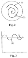
- FIG. 2 shows how a light spot 22 guided by this controlled movement 21 projects onto a diametrical surface at the end of the optical fiber of the deflection unit 5 .
- regulating the light spot 22 is at least approximately brought to the center of the optical fiber.
- Fig. 3 shows how the average intensity signal 31 on the detectors 10 and 11 has a superimposed modulation signal 32 when the fiber axis does not scan concentrically around the optical axis of the opto-mechanical system.
- the function of the controller 18 is to move the fine alignment mechanism 3, the end of the fiber 7, and / or the lens 4 such that this modulation signal 32 reaches a minimum value or the value zero.
- the device according to the invention works as follows:
- the light wave received by the optical receiving unit 2, 3 is focused via the fine alignment unit 3 and with the aid of the lens 4 approximately onto the center of the single-mode fiber 7 in the fiber mutator 5 when the control unit is at rest.
- a movement ( FIG. 2 ) of the light spot 22 about the center of the single-mode fiber 7 is effected by the fiber mutator 5 .
- the light spot 22 describes a high-frequency circular movement about the optical axis of the receiving optics.
- the end of the fiber 7 is moved by the nutator, one has at the end of the fiber, in the detectors 10 and 11 no spatial movement of the exiting light more.
- the rotational movement by means of the nutator 5 causes an intensity modulation ( FIG. 3 ) if the scanning movement does not take place exactly concentrically around the light spot.
- the high-frequency mechanical scanning movement of the fiber end caused by the deflection unit 5 can be controlled, for example, by means of a lateral displacement mechanism or by means of a bending element.
- Fast lateral shift units with small movements are known, for example, from optoelectronic readers such as CD players.
- bending elements can be easily realized from piezoceramic tubes with segmented electrodes. These tubes are firmly fixed only in one area, so that they can bend in the longitudinal direction by the piezoelectric effect. All mechanisms have in common that they are controlled via so-called IQ signals. After the IQ demodulation of the intensity signal is finally obtained the spatial error between the light spot 22 and the fiber axis.
- the error signal Sr causes via the controller 18 that the storage error is minimized.
- the relative offset between the intensity distribution of the Rx light in the focal plane of the lens 4 and the end of the fiber 7 generated by the rotational movement thus causes a temporally asymmetric intensity signal on the detectors 10 and 11, if the fiber axis is not concentric about the optical axis of the optomechanical Systems scans.
- the scanning point detector is thus, with very good approximation, replaced by the mode field of a monomode fiber.
- the scan radius should not exceed 1/10 of the mode field radius.
- the light wave is divided by the beam splitter into two nearly identical sub-beams, which are each supplied to one of the detectors 10 and 11 after the light of the local laser 12 has been coupled into the luminous flux via the optical fiber coupler 6 .
- two error component signals are generated, which are each implemented via a corresponding front-end transimpedance amplifier 15 and 16 in voltages Sa and Sb .
- the spatial error signal Sr is obtained by subtraction, and by sign-equitable addition of the error component signals Sa and Sb results in an output signal corresponding to the original data signal.
- the superposition of the local laser wave with the Rx-wave takes place only in the glass fiber, so that the spatial correlation degree between local laser and Rx field will be 1, that is, it is guaranteed streak-free overlay.
- the spatial correlation degree between local laser and Rx field will be 1, that is, it is guaranteed streak-free overlay.
- For optimization in the Adjustment or for a later optimization in the operation can then be guaranteed by one streak-free overlay and adjust to the absolute amplitude maximum.
- the optimal, that is streak-free adjustment state can then no longer the maximum intensity can be found alone.
- the level difference between the main maximum and one of the secondary maxima relatively small. It then exists always the latent danger that the tracking controller gets out of step and on one Secondary maximum of the intensity distribution controls what the linear control range then considerably restricts.
- the receiving fiber 7 which may be relatively long, it is possible to accommodate the receiver front-end (RFE), i.e. the detectors 10 , 11 and the amplifiers 15 , 16, at a relatively long distance from the optics.
- the optical fibers may be housed in a flexible protective cable or have a flexible sheath. The resulting heat in the RFE is thus optimally decoupled from the optics, and it no longer has to be reckoned with by the RFE induced thermal misalignments in the optical subsystem.
- the optical parts 2, 3, 4 and 5 can thus also be arranged at a relatively large distance from the data electronics and the RFE, which are located in the remote electronics unit.
- the device according to the present invention can advantageously replace the elements 16 and 26 of the optical bench according to the cited Offenlegungsschrift EP-0 844 473 A1 .
- the controller or computer controller 18 may be configured to cause movement of the movable end of the optical fiber 7 about the center of the focused point 22 of the information shaft 1 while the lens 4 is stationary.
- the controller 18 may cause movement of the lens 4 to move the focused light spot 22 of the information wave 1 about the center of the optical fiber 7 while the optical fiber is at rest.
- the device according to the present invention can be used for the same or similar purposes as in the mentioned patent application EP 0 831 604 A1 .
Landscapes
- Physics & Mathematics (AREA)
- Electromagnetism (AREA)
- Engineering & Computer Science (AREA)
- Computer Networks & Wireless Communication (AREA)
- Signal Processing (AREA)
- Astronomy & Astrophysics (AREA)
- General Physics & Mathematics (AREA)
- Optical Communication System (AREA)
- Optical Couplings Of Light Guides (AREA)
Abstract
Description
Die Erfindung bezieht sich auf ein Verfahren und eine Vorrichtung zur Erzeugung eines Fehlersignals
bei kohärentem Überlagerungsempfang von Lichtwellen nach dem Oberbegriff
des Patentanspruchs 1 bzw. 3.The invention relates to a method and a device for generating an error signal with coherent heterodyne reception of light waves according to the preamble of
Dokument 'A novel angular discriminator for spatial tracking in free-space laser communication', Fung J S C, Proceedings of the SPIE, Bd. 1417, 21 Januar 1991, Seiten 224-232, offenbart ein Verfahren und eine Vorrichtung zur Erzeugung eines Fehlersignals bei kohärentem Überlagerungsempfang von Lichtwellen, derart, dass eine Informationslichtwelle einem Empfangsteleskop zugeführt wird, dass der Informationslichtwelle Licht eines lokalen Lasers überlagert wird, dass die Informationslichtwelle nach der Zumischung des Lichts des lokalen Lasers über einen Strahlteiler in zwei Strahlanteile aufgeteilt wird, dass diese Strahlanteile je einem Detektor zur Erzeugung eines Fehlersignals zugeführt werden, und dass im Fokussierbereich der Empfangseinrichtung eine Scanvorrichtung ("Fast Steering Mirror") wirksam ist.Document 'A novel angular discriminator for spatial tracking in free-space laser communication ', Fung J S C, Proceedings of the SPIE, Vol. 1417, 21 January 1991, pages 224-232 discloses a method and apparatus for generating an error signal with coherent heterodyne reception of light waves, such that a Information light wave is fed to a receiving telescope that the Information light wave light of a local laser is superimposed on that Information light wave after admixing the light of the local laser via a Beam splitter is divided into two beam components, that these beam components each have a detector be supplied to generate an error signal, and that in the focusing of the Receiving device, a scanning device ("Fast Steering Mirror") is effective.
Zur Kontrolle der optischen Ausrichtung zweier Lichtwellen bei kohärentem Überlagerungsempfang ist aus der europäischen Offenlegungsschrift EP-0 831 604 A1 eine Vorrichtung mit einem lokalen Laser und mit zwei Detektoren bekannt, die je zwei identische Detektorhälften umfassen, die jeweils durch eine streifenförmige Unterbrechung oder Lücken in der Photodiodenelektrodenfläche zwischen den benachbarten Hälften getrennt sind, wobei die Lücken der zwei Detektoren orthogonal zueinander angeordnet sind. Diese Vorrichtung wird als richtungsselektiver optischer Einmodenempfänger benutzt. Dabei ist sowohl in einem Empfangsteleskop dieser Vorrichtung als auch im Strahlengang des lokalen Lasers eine Abschattung vorhanden. Dies erlaubt, ein Fehlersignal für eine räumliche Strahlregelung eines optischen Überlagerungsempfängers unter weitgehender Vermeidung der systematischen Verluste und unter gleichzeitiger minimaler Beeinträchtigung des zu übertragenden Datensignals mit einem guten Signal-Rausch-Verhältnis zu erzeugen. To control the optical alignment of two light waves with coherent heterodyne reception, a device with a local laser and with two detectors is known from European published patent application EP-0 831 604 A1 , each comprising two identical detector halves, each characterized by a strip-shaped interruption or gaps in the Photodiode electrode surface between the adjacent halves are separated, wherein the gaps of the two detectors are arranged orthogonal to each other. This device is used as a directionally selective single-mode optical receiver. In this case, a shading is present both in a receiving telescope of this device and in the beam path of the local laser. This allows to generate an error signal for spatial beam control of an optical heterodyne receiver while largely avoiding the systematic losses while minimizing the degradation of the data signal to be transmitted with a good signal-to-noise ratio.
Ferner ist aus der europäischen Offenlegungsschrift EP-0 844 473 A1 eine optische Bank bekannt, deren Bankstruktur derart ausgebildet ist, dass bei einer Wärmedilatation von Armen, die zur Verbindung von Aufnahmeteilen für verschiedene optische Einheiten vorgesehen sind, die Aufnahmeteile ohne Verkippung quer zu Achsen verschiebbar sind, die unter sich und relativ zur Bankstruktur bestimmte Winkellagen einnehmen. Eine solche optische Bank kann mit der eingangs erwähnten Vorrichtung kombiniert werden.Furthermore, European Patent Application EP-A-0 844 473 discloses an optical bench whose bank structure is designed in such a way that, in the case of heat dilation of arms which are provided for connection of receiving parts for different optical units, the receiving parts can be displaced transversely to axes without tilting are that occupy certain angular positions below and relative to the bank structure. Such an optical bench can be combined with the device mentioned above.
Ein solches "Tracking-Sensor"-Verfahren erlaubt zwar ein gleichzeitiges Kommunizieren und Bestimmen des räumlichen Trackingfehlers, die entsprechende Vorrichtung erweist sich jedoch als nachteilig im Hinblick auf den relativ hohen Justieraufwand bei deren Herstellung.Although such a "tracking sensor" method allows simultaneous communication and Determine the spatial tracking error, the corresponding device proves However, as disadvantageous in view of the relatively high Justieraufwand in their preparation.
Es ist daher Aufgabe der Erfindung, ein Verfahren und eine Vorrichtung zur Erzeugung eines Fehlersignals bei kohärentem Überlagerungsempfang von Lichtwellen zu schaffen, die zu einer einfacheren Justierung eines solchen Systems führt.It is therefore an object of the invention to provide a method and apparatus for generating of an error signal in coherent heterodyne reception of light waves, the leads to a simpler adjustment of such a system.
Diese Aufgabe wird in vorteilhafter Weise erfindungsgemäss durch ein Verfahren und eine
Vorrichtung nach Patentanspruch 1 bzw. 3 gelöst.This object is solved according to the invention by a method and a device according to
Das neue Empfangsprinzip, bei dem auf die sogenannte Freistrahlüberlagerung verzichtet wird, bringt nicht nur eine Vereinfachung des Verfahrens zur Optimierung der Justierung, sondern auch eine Vereinfachung des optomechanischen Aufbaus mit sich.The new reception principle, which dispenses with the so-called free jet overlay not only brings a simplification of the method for optimizing the adjustment, but also a simplification of the optomechanical structure with it.
Andere vorteilhafte Ausführungen der Erfindung ergeben sich aus den weiteren abhängigen Ansprüchen.Other advantageous embodiments of the invention will become apparent from the other dependent Claims.
Die Erfindung wird nachfolgend beispielsweise an Hand einer Zeichnung näher erläutert. Es zeigt:
- Fig. 1
- eine schematische Darstellung einer erfindungsgemässen Vorrichtung,
- Fig. 2
- eine schematische Darstellung der Bewegung eines Lichtflecks auf der Stirnfläche einer Lichtwellenfaser,
- Fig. 3
- ein schematisches Diagramm des zeitlich asymmetrischen Intensitätssignals auf den Detektoren, falls die Faserachse nicht konzentrisch um die optische Achse des optomechanischen Systems scannt, und
- Fig. 4
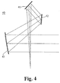
- eine schematische Darstellung eines sogenannten Kutter-Teleskops ohne zentrale Abschattung.
- Fig. 1
- a schematic representation of an inventive device,
- Fig. 2
- a schematic representation of the movement of a light spot on the end face of an optical fiber,
- Fig. 3
- a schematic diagram of the time-asymmetric intensity signal on the detectors, if the fiber axis does not scan concentrically about the optical axis of the optomechanical system, and
- Fig. 4
- a schematic representation of a so-called cutter telescope without central shading.
Ähnlich wie bei der aus der erwähnten EP-0 831 604 A1 bekannten Vorrichtung wird
gemäss Fig. 1 eine ein Datensignal tragende Rx-Welle oder Informationslichtwelle 1 über
eine Empfangseinheit bestehend aus einem Empfangsteleskop 2, einem
Feinausrichtmechanismus 3 und einer Linse 4 empfangen und einem Strahlteiler zugeführt.Similar to the well-known from the aforementioned EP-0831604 A1 apparatus according to FIG. 1, a received a data signal carrying Rx-wave or information light shaft 1 via a receiving unit consisting of a
Im Gegensatz zur erwähnten Vorrichtung weist der Strahlteiler nach der vorliegenden
Erfindung einen Fibernutator 5 und einen Lichtwellenleiter-Koppler 6 auf. An den
Fibernutator 5 ist ein Ende einer polarisationserhaltenden Monomode-Faser 7
angeschlossen, um die über die optische Empfangseinheit empfangene Strahlung bis zum
LWL-Koppler 6 und über weitere Monomode-Fasern 8 und 9 bis zu je einem Detektor 10
bzw. 11 zu führen. Ein solcher Fibernutator ist im wesentlichen eine Ablenkeinheit mit einer
Faser, die durch einen Piezomechanismus zur Nutation angetrieben wird. An einen lokalen
Laser 12 ist eine weitere vorzugsweise polarisationserhaltende Monomode-Faser 13
angeschlossen, um die vom lokalen Laser 12 erzeugte Strahlung bis zum LWL-Koppler 6
und dann über die Monomode-Fasern 8 und 9 bis zu den zwei Detektoren 10 bzw. 11 zu
führen. Die Detektoren 10 und 11 sind nicht wie bei der bekannten Vorrichtung gesplittet. Die
Ablenkeinheit 5 kann über einen Bus oder Leitungen Steuersignale Sp von einer
Aussteuerung 14 erhalten. Der LWL-Koppler 6 ist vorzugsweise ein 50%-zu-50%-Koppler.
Ein einfacher und gleichzeitig inhärent langzeitstabiler Aufbau kann mit einem polarisationserhaltenden
Faserkoppler erreicht werden.In contrast to the mentioned device, the beam splitter according to the present invention, a
Als Ablenkeinheit kann auch an Stelle des mechanischen Fibernutators ein elektrooptischer Deflektor verwendet werden, bei dem eine elektrische Spannung einen linearen elektrischen Feldgradienten über die Apertur eines elektrooptischen Kristalls erzeugt. Bei einem solchen Deflektor ist auch eine Apertur von etwa 1 mm ohne weiteres erreichbar.As deflection unit can also be used instead of the mechanical Fibernutators an electro-optical Deflector are used, in which an electrical voltage is a linear electric Field gradients generated across the aperture of an electro-optic crystal. In such a Deflector is also an aperture of about 1 mm easily accessible.
Die Detektoren 10 und 11 liefern über je einen Verstärker 15 bzw. 16 Signale Sa bzw. Sb,
die als Nutzsignale verwendet werden. Diese Signale Sa und Sb werden jedoch auch den
Differenzeingängen eines Differenzverstärkers 17 zugeführt. Die Vorrichtung umfasst auch
einen Regler oder Computer/Regler 18, der eingangsseitig mit dem Ausgang des
Differenzverstärkers 17 verbunden ist und ausgangsseitig mindestens ein Regelsignal Sd für
die Steuereinheit 14, die auch Deflektor-Aussteuerung genannt wird, und/oder weitere
Regelsignale Sf und/oder So für die Feinregelung des Feinausrichtmechanismus 3 bzw. für
die Bewegung der Linse 4 liefert. Der Regler 18 kann zusätzlich Regelsignale Sg für eine
Grobregelung des Empfangsteleskops 2 abgeben und gegebenenfalls Rückmeldesignale Se
von der Steuereinheit 14 erhalten.The
Fig. 2 zeigt, wie sich ein durch diese geregelte Bewegung 21 geführter Lichtfleck 22 auf eine
diametrale Fläche am Ende der Lichtwellenfaser der Ablenkeinheit 5 projiziert. Durch die
Regelung wird der Lichtfleck 22 zumindest angenähert bis zum Zentrum der Lichtwellenfaser
gebracht. FIG. 2 shows how a
Fig. 3 zeigt wie das mittlere Intensitätssignal 31 auf den Detektoren 10 und 11 ein
überlagertes Modulationssignal 32 aufweist, wenn die Faserachse nicht konzentrisch um die
optische Achse des optomechanischen Systems scannt. Die Aufgabe des Reglers 18
besteht darin, den Feinausrichtemechanismus 3, das Ende der Faser 7 und/oder die Linse 4,
derart zu bewegen, dass dieses Modulationssignal 32 einen minimalen Wert oder den Wert
Null erreicht. Fig. 3 shows how the
Das in Fig. 4 dargestellte Kutter-Teleskop 40 weist drei Spiegel 41, 42, 43 auf, die derart
angeordnet sind, dass es im Gegensatz zu einem Cassegrain-System keine zentrale
Abschattung verursacht, was im Zusammenhang mit der vorliegenden Erfindung auch von
Bedeutung ist, um die Energie des absoluten Zentralmaximums eines Beugungsbildes voll
auszunutzen, das einem bandbegrenzten Impuls mit cos2 -Spektrum und Nulldurchgängen
bei t = iT (i = 1, 2, 3 ... ) ähnlich ist, und um dadurch einen grösseren Wirkungsgrad zu
erreichen.The
Die erfindungsgemässe Vorrichtung funktioniert folgendermassen:
Die von der optischen Empfangseinheit 2, 3 empfangene Lichtwelle wird über die
Feinausrichteinheit 3 und mit Hilfe der Linse 4 etwa auf das Zentrum der Monomode-Faser 7
im Fibernutator 5 fokussiert, wenn die Steuereinheit ruht. Wenn die Steuereinheit 14 aktiv
ist, wird durch den Fibernutator 5 eine Bewegung (Fig. 2) des Lichtflecks 22 um das
Zentrum der Monomode-Faser 7 bewirkt. Vorzugsweise beschreibt der Lichtfleck 22 eine
hochfrequente Kreisbewegung um die optische Achse der Empfangsoptik. Obwohl das Ende
der Faser 7 durch den Nutator bewegt wird, hat man am Ende der Faser, bei den Detektoren
10 und 11 keine räumliche Bewegung des austretenden Lichts mehr. Vielmehr verursacht
die Rotationsbewegung mittels des Nutators 5 eine Intensitätsmodulation (Fig. 3) falls die
Scanbewegung nicht exakt konzentrisch um den Lichtfleck erfolgt. The device according to the invention works as follows:
The light wave received by the
Die durch die Ablenkeinheit 5 bewirkte hochfrequente mechanische Scanbewegung des
Faserendes kann beispielsweise mittels eines Lateralverschiebemechanismus oder mittels
eines Biegeelements gesteuert werden. Schnelle Lateralschiebeeinheiten mit kleinen
Bewegungen sind beispielsweise aus optoelektronischen Lesegeräten wie CD-Spielern
bekannt. Biegeelemente lassen sich dagegen einfach aus piezokeramischen Röhrchen mit
segmentierten Elektroden realisieren. Diese Röhrchen sind nur in einem Bereich fest fixiert,
damit sie sich durch den Piezoeffekt in Längsrichtung biegen können. Allen Mechanismen
gemeinsam ist, dass sie über sogenannte I-Q-Signale angesteuert werden. Nach erfolgter I-Q-Demodulation
des Intensitätssignals erhält man schliesslich den räumlichen Fehler
zwischen dem Lichtfleck 22 und der Faserachse. Das Fehlersignal Sr bewirkt über den
Regler 18, dass der Ablagefehler minimiert wird.The high-frequency mechanical scanning movement of the fiber end caused by the
Der durch die Rotationsbewegung erzeugte relative Versatz zwischen der
Intensitätsverteilung des Rx-Lichts in der Fokalebene der Linse 4 und dem Ende der Faser 7
bewirkt somit ein zeitlich asymmetrisches Intensitätssignal auf den Detektoren 10 und 11,
falls die Faserachse nicht konzentrisch um die optische Achse des optomechanischen
Systems scannt. Der abtastende Punktdetektor wird somit, und zwar mit sehr guter
Näherung, durch das Modenfeld einer monomodigen Faser ersetzt. Um einen zu hohen
Signalabfall des in die Faser eingekoppelten Lichts zu vermeiden, sollte der Scanradius 1/10
des Modenfeldradius nicht überschreiten.The relative offset between the intensity distribution of the Rx light in the focal plane of the lens 4 and the end of the fiber 7 generated by the rotational movement thus causes a temporally asymmetric intensity signal on the
Die Lichtwelle wird durch den Strahlteiler in zwei nahezu identische Teilstrahlen aufgeteilt,
die je einem der Detektoren 10 und 11 zugeführt werden, nachdem über den LWL-Koppler 6
das Licht des lokalen Lasers 12 in den Lichtstrom eingekoppelt wurde. Von den zwei
Detektoren 10, 11, werden je zwei Fehleranteilsignale erzeugt, die je über einen
entsprechenden Front-End-Transimpedanz-Verstärker 15 bzw. 16 in Spannungen Sa bzw.
Sb umgesetzt werden. Aus den Signalen Sa und Sb wird durch Differenzbildung das
räumliche Fehlersignal Sr gewonnen, und durch vorzeichengerechte Addition der
Fehleranteilsignale Sa und Sb ergibt sich ein dem ursprünglichen Datensignal
entsprechendes Ausgangssignal.The light wave is divided by the beam splitter into two nearly identical sub-beams, which are each supplied to one of the
Die Überlagerung der Lokal-Laser-Welle mit der Rx-Welle erfolgt erst in der Glasfaser, so dass der räumliche Korrelationsgrad zwischen Lokal-Laser und Rx-Feld gleich 1 sein wird, das heisst, es erfolgt garantiert streifenfreie Überlagerung. Für die Optimierung bei der Justage bzw. für eine spätere Optimierung im Betrieb kann man dann von einer garantiert streifenfreien Überlagerung ausgehen und auf das absolute Amplitudenmaximum justieren. Dies erweist sich als sehr vorteilhaft gegenüber der Freistrahlüberlagerung, bei der es im Gegensatz zum erfindungsgemässen Verfahren vorkommen kann, dass bei der Überlagerung der beiden Wellen noch Interferenzstreifen infolge eines Kippwinkels auftreten. Der optimale, das heisst streifenfreie Justierzustand kann dann nicht mehr durch das Intensitätsmaximum alleine gefunden werden. Zudem ist dann der Pegelabstand zwischen dem Hauptmaximum und einem der Nebenmaxima relativ klein. Es besteht dann immer die latente Gefahr, dass der Trackingregler aus dem Tritt gerät und auf einem Nebenmaximum der Intensitätsverteilung regelt, was den linearen Regelbereich dann erheblich einschränkt.The superposition of the local laser wave with the Rx-wave takes place only in the glass fiber, so that the spatial correlation degree between local laser and Rx field will be 1, that is, it is guaranteed streak-free overlay. For optimization in the Adjustment or for a later optimization in the operation can then be guaranteed by one streak-free overlay and adjust to the absolute amplitude maximum. This proves to be very advantageous over the free jet overlay, where it is in Contrary to the inventive method may occur that in the Superposition of the two waves nor interference fringes due to a tilt angle occur. The optimal, that is streak-free adjustment state can then no longer the maximum intensity can be found alone. In addition, then the level difference between the main maximum and one of the secondary maxima relatively small. It then exists always the latent danger that the tracking controller gets out of step and on one Secondary maximum of the intensity distribution controls what the linear control range then considerably restricts.
Durch die Verwendung der Empfangsfaser 7, die relativ lang sein kann, ist es möglich, das
Receiver-Front-End (RFE), das heisst die Detektoren 10, 11 und die Verstärker 15, 16 in
einer relativ weiten Entfernung von der Optik unterzubringen. Zu diesem Zweck können die
Lichtwellenfasern in einem flexiblen Schutzkabel untergebracht sein oder eine flexible
Ummantelung aufweisen. Die im RFE entstehende Wärme ist somit optimal von der Optik
abgekoppelt, und es muss nicht mehr mit durch das RFE induzierten thermischen
Dejustierungen im optischen Subsystem gerechnet werden. Die optischen Teile 2, 3, 4 und 5
können somit auch in einem relativ grossen Abstand zur Datenelektronik und zum RFE
angeordnet werden, die sich in der abgesetzten Elektronik-Einheit befinden. Durch die
Beweglichkeit von Teilen der Faser lassen sich somit sämtliche Probleme beseitigen, die
sich bei Verwendung von langen Mikrowellenleitungen (Dämpfung, EMC (Electromagnetic
Compatibility)) ergeben, auch wenn man dann eine Koaxleitung von der Elektronik-Einheit
zum optischen Kopf führen muss, um auf dieser Leitung die niederfrequenten
Trackingfehlersignale (BW ≈ 10 kHz) wieder nach vorne zu führen.By using the receiving fiber 7, which may be relatively long, it is possible to accommodate the receiver front-end (RFE), i.e. the
Die erfindungsgemässe Vorrichtung erweist sich zudem als besonders vorteilhaft im Hinblick
darauf, dass sie eine hohe Langzeitstabilität aufweist, dass sie mit einem relativ einfachen
Algorithmus bei der Strahlüberlagerung optimiert werden kann, dass sich bei hochfrequenten
Datenströmen (Taktrate = 1000 Mbps) keine besonders signifikante Dämpfung auf die
Verbindungsleitung zwischen dem Fibernutator und dem abgesetzten Receiver-Front-End
(RFE) (Kabellängen > 3 m) ergibt, dass sie keiner zusätzlichen
Leitungs-Treiberelektronik bedarf, dass die Kabel nicht fix verlegt werden müssen, so dass
auch bewegliche Teilbereiche möglich sind, dass sie bezüglich EMC-Störungen
unproblematisch ist, dass bei Breitbandsystemen RFEs mit Bandbreiten >> 1 Ghz zum
Einsatz kommen können, und dass eine hohe Wärmeentwicklung infolge der HF-Elektronik
in unmittelbarer Nähe der Optik vermieden wird. In diesem Sinne kann die Vorrichtung nach
der vorliegenden Erfindung in vorteilhafter Weise die Elemente 16 und 26 der optischen
Bank nach der erwähnten Offenlegungsschrift EP-0 844 473 A1 ersetzen.The inventive device also proves to be particularly advantageous in view of the fact that it has a high long-term stability that it can be optimized with a relatively simple algorithm at the beam superposition, that at high-frequency data streams (clock rate = 1000 Mbps) no particularly significant attenuation the connecting cable between the fiber hub and the remote receiver front-end (RFE) (cable lengths> 3 m) shows that it requires no additional line driver electronics, that the cables do not need to be fixed, so that movable sections are possible, that it is unproblematic with respect to EMC interference that can be used with broadband systems RFEs with bandwidths >> 1 Ghz, and that a high heat generation due to the RF electronics in the immediate vicinity of the optics is avoided. In this sense, the device according to the present invention can advantageously replace the
Bei einer Ausführung der Erfindung kann der Regler oder Computer-Regler 18 derart
ausgebildet sein, dass eine Bewegung des beweglichen Endes der Lichtwellenfaser 7 um
das Zentrum des fokussierten Punktes 22 der Informationswelle 1 bei ruhender Linse 4
bewirkt wird.In one embodiment of the invention, the controller or
Bei einer anderen Ausführung der Erfindung kann der Regler 18 eine Bewegung der Linse 4
bewirken, um den fokussierten Lichtfleck 22 der Informationswelle 1 um das Zentrum der
Lichtwellenfaser 7 bei ruhender Lichtwellenfaser zu bewegen.In another embodiment of the invention, the
Bei einer weiteren Ausführung der Erfindung kann eine Kombination beider Bewegungen bewirkt werden.In a further embodiment of the invention, a combination of both movements be effected.
Die Vorrichtung nach der vorliegenden Erfindung kann für denselben oder ähnliche Zwecke wie bei der erwähnten Patentanmeldung EP 0 831 604 A1 verwendet werden.The device according to the present invention can be used for the same or similar purposes as in the mentioned patent application EP 0 831 604 A1 .
Die oben dargelegten Ausführungsbeispiele sind lediglich zur Veranschaulichung des neuen Verfahrens und der neuen Vorrichtung zu verstehen. Im Rahmen der Ansprüche sind auch andere Ausführungen der Erfindung, wie sie sich für den Fachmann in naheliegende Weise daraus ergeben, möglich.The embodiments set forth above are merely illustrative of the new Process and the new device to understand. Within the scope of the claims are also other embodiments of the invention, as will be apparent to one skilled in the art resulting from it, possible.
Claims (9)
- Procedure for generation of an error signal in the case of coherent heterodyne reception of light waves, such that:characterized in thatan information light wave (1) of a reception device (2, 3, 4, 5) is conveyed by a receiving telescope,the information light wave (1) is combined with the light of a local laser (12),the information light wave (1), after admixture of the light of a local laser (12), is divided into two beam portions by a beam splitter (6),each of these beam portions is fed into a detector (10, 11) for generation of an error signal (Sr),the information light wave (1) and the light of the local laser (12) are each led along a lightwave fibre (7 or 13) to the beam splitter (6),each of the beam portions is led via a further lightwave fibre (8, 9) to the detectors (10, 11), andin the focusing zone of the reception device (2, 3, 4, 5) at a frontal surface of the lightwave fibre (7), a deflector unit (5) operates,one end of the lightwave fibre (7) is moved by the deflector unit (5), so thatby means of this movement of the end of this lightwave fibre (7), a focus spot (22) of the information light wave (1) is focused on the centre of this lightwave fibre (7), and so thatthe error signal (Sr) is fed back to the reception device (2, 3, 4, 5) and by means of a regulator (18) causes the deviation error to be minimized.
- Procedure according to Claim 1,
characterized in that
the information light wave (1) is focused on a frontal surface at the end of a lightwave fibre (7) by a lens (4). - Device for generation of an error signal in the case of coherent heterodyne reception of light waves, the device consisting of:the device being so arranged thatan opto-mechanical reception unit (2, 3, 4) with a reception telescope (2),a local laser (12),a beam splitter (6), andtwo detectors (10, 11),characterized in that the device is furthermore so arranged thatan information light wave (1) is received with the reception telescope (2),the information light wave (1) is combined with light from the local laser (12),the information light wave (1), after admixture of the light of a local laser (12), is divided by a beam splitter (6) into two beam portions, each of which is fed into a detector (10, 11) for generation of an error signal (Sr), the opto-mechanical reception unit (2, 3, 4) being arranged opposite a frontal surface at the end of a lightwave fibre (7) in order to enable the information light wave (1) received to be sent on through the lightwave fibre (7) to the beam splitter (6) which is connected via another lightwave fibre (13) to the local laser (12) and via two more lightwave fibres (8, 9) each leading to a detector (10, 11) for generation of an error signal (Sr),the information light wave (1) and the light of the local laser (12) are led via the lightwave fibres (7 or 13) to the beam splitter (6) for division into two beam portions, which are then led separately each via one of the two further lightwave fibres (8, 9), andthe error signal (Sr) is fed back to the reception device, so that the light wave received is focused on the centre of the lightwave fibre (7).
- Device according to Claim 3,
characterized in that
a control unit (14) is present, acting on this frontal surface of the lightwave fibre (7) located in the focusing zone of the optical reception system. - Device according to Claim 3 or 4,
characterized in that
a regulator (18) is present to cause a movement of the lightwave fibre (7) about the centre of the focused spot (22) of the information light wave (1) and/or to cause a movement of a lens (4) of the opto-mechanical reception unit (2, 3, 4) so that the focus spot (22) of the information light wave (1) is projected on to a central cross-section zone of the lightwave fibre (7). - Device according to any one of Claims 3 to 5,
characterized in that
at least one of these lightwave fibres (7, 8, 9, 13) is a polarization-conserving single-mode fibre. - Device according to any one of Claims 3 to 6,
characterized in that
the reception telescope (2) can be focused with no central shadowing effect. - Device according to any one of Claims 3 to 7,
characterized in that
the lightwave fibres (7, 8, 9, 13) are so dimensioned and arranged that microwave conductors are avoided. - Device according to Claims 4 and 5
characterized in that
the control unit (14) and the regulator (18) are arranged so as to move a fibre nutator (5) or an electro-optical deflector and/or a laterally movable focusing lens (4).
Applications Claiming Priority (2)
| Application Number | Priority Date | Filing Date | Title |
|---|---|---|---|
| CH253298 | 1998-12-22 | ||
| CH253298 | 1998-12-22 |
Publications (2)
| Publication Number | Publication Date |
|---|---|
| EP1014604A1 EP1014604A1 (en) | 2000-06-28 |
| EP1014604B1 true EP1014604B1 (en) | 2005-06-22 |
Family
ID=4235925
Family Applications (1)
| Application Number | Title | Priority Date | Filing Date |
|---|---|---|---|
| EP99116491A Expired - Lifetime EP1014604B1 (en) | 1998-12-22 | 1999-08-23 | Method and apparatus for producing an error signal in coherent heterodyne reception of lightwaves |
Country Status (6)
| Country | Link |
|---|---|
| US (1) | US6570695B1 (en) |
| EP (1) | EP1014604B1 (en) |
| JP (1) | JP2000196531A (en) |
| AT (1) | ATE298478T1 (en) |
| CA (1) | CA2282157A1 (en) |
| DE (1) | DE59912199D1 (en) |
Families Citing this family (7)
| Publication number | Priority date | Publication date | Assignee | Title |
|---|---|---|---|---|
| US20030035178A1 (en) * | 2001-08-17 | 2003-02-20 | George Seaver | Solid-state system for tracking and regulating optical beams |
| US8301032B2 (en) * | 2008-02-12 | 2012-10-30 | Arun Kumar Majumdar | Wide field-of-view amplified fiber-retro for secure high data rate communications and remote data transfer |
| DE102011113148B4 (en) * | 2011-09-14 | 2017-03-09 | Tesat-Spacecom Gmbh & Co.Kg | System for communication between two communication platforms and associated objects |
| US9813151B2 (en) | 2014-08-05 | 2017-11-07 | Massachusetts Institute Of Technology | Free-space optical communication module for small satellites |
| WO2016112289A2 (en) | 2015-01-09 | 2016-07-14 | Massachusetts Institute Of Technology | Network of extremely high burst rate optical downlinks |
| WO2016190934A2 (en) | 2015-02-27 | 2016-12-01 | Massachusetts Institute Of Technology | Methods, systems, and apparatus for global multiple-access optical communications |
| US11119218B2 (en) * | 2018-04-03 | 2021-09-14 | GM Global Technology Operations LLC | Coherent lidar system with extended field of view |
Family Cites Families (8)
| Publication number | Priority date | Publication date | Assignee | Title |
|---|---|---|---|---|
| FR2632075A1 (en) * | 1988-05-31 | 1989-12-01 | Technomed Int Sa | DEVICE FOR TRANSFERRING A RADIUS OR OPTICAL BEAM EMITTED BY A LASER ONTO AN OPTICAL FIBER, AND APPARATUS FOR GENERATING SHOCKWAVES FOR THE DESTRUCTION OF TARGETS, IN PARTICULAR TISSUES, LITHIASES OR CONCRETIONS, PROVIDED WITH SUCH A DEVICE |
| JPH0734080B2 (en) * | 1988-10-20 | 1995-04-12 | 富士通株式会社 | Heterodyne detection receiver for coherent optical communication |
| US5062150A (en) * | 1989-01-23 | 1991-10-29 | Massachusetts Institute Of Technology | Fiber-based free-space optical system |
| US5252852A (en) * | 1989-03-14 | 1993-10-12 | Fujitsu Limited | Semiconductor device having flip chip bonding pads matched with pin photodiodes in a symmetrical layout configuration |
| US5808472A (en) * | 1996-09-17 | 1998-09-15 | Hughes Electronics Corporation | Apparatus and methods for positioning optical fibers and other resilient members |
| DE59700268D1 (en) * | 1996-09-22 | 1999-08-26 | Contraves Ag | Method and device for controlling the alignment of two light waves with coherent overlay reception |
| EP0844748B1 (en) * | 1996-11-25 | 1999-06-16 | Oerlikon Contraves AG | Method and apparatus of optical data transmission along a free space path |
| DE59801613D1 (en) * | 1997-12-21 | 2001-11-08 | Contraves Space Ag Zuerich | Device for directional radiation and for the directional reception of modulated light waves |
-
1999
- 1999-08-23 AT AT99116491T patent/ATE298478T1/en not_active IP Right Cessation
- 1999-08-23 DE DE59912199T patent/DE59912199D1/en not_active Expired - Lifetime
- 1999-08-23 EP EP99116491A patent/EP1014604B1/en not_active Expired - Lifetime
- 1999-09-13 CA CA002282157A patent/CA2282157A1/en not_active Abandoned
- 1999-10-05 US US09/410,961 patent/US6570695B1/en not_active Expired - Lifetime
- 1999-10-08 JP JP11287873A patent/JP2000196531A/en active Pending
Also Published As
| Publication number | Publication date |
|---|---|
| ATE298478T1 (en) | 2005-07-15 |
| CA2282157A1 (en) | 2000-06-22 |
| EP1014604A1 (en) | 2000-06-28 |
| US6570695B1 (en) | 2003-05-27 |
| DE59912199D1 (en) | 2005-07-28 |
| JP2000196531A (en) | 2000-07-14 |
Similar Documents
| Publication | Publication Date | Title |
|---|---|---|
| EP0154865B1 (en) | Position correcting device for a laser beam passing an articulated waveguide | |
| EP0383138A2 (en) | Device for the direct optical reception of a plurality of wave lengths | |
| EP3156838B1 (en) | Scanner head and device with scanner head | |
| DE102018106899A1 (en) | MEMS steering mirrors for integrated photonics applications | |
| DE102019200225B4 (en) | Structure for receiving an optical data signal, data transmission system and method for adjusting a structure for receiving and / or sending an optical data signal | |
| DE3831839A1 (en) | OPTICAL SEND AND / OR RECEPTION BLOCK | |
| EP1014604B1 (en) | Method and apparatus for producing an error signal in coherent heterodyne reception of lightwaves | |
| EP0992823A2 (en) | Method for aligning an electrooptical component and such a component | |
| WO1994017575A1 (en) | Phase-controlled fractal laser system | |
| EP0831604B1 (en) | Method and system for controlling the position of two lightwaves in heterodyne coherent reception | |
| EP0400161A1 (en) | Arrangement for the optical coupling of an electrooptical converter module to a light guide by means of two lenses | |
| EP1111816B1 (en) | Method and apparatus for establishing connection between satellites | |
| WO1996006377A1 (en) | Device for feeding the light beam from a uv laser into a laser scanning microscope | |
| EP1378074B1 (en) | Device and system for the optical transmission of data between satellites | |
| DE19701155C1 (en) | Interruption free deflection device for light beam | |
| DE102019124599B4 (en) | METHOD OF DETECTING AN OBJECT AND LIDAR SYSTEM | |
| DE102019124553A1 (en) | CHIP-SCALED LIDAR WITH IMPROVED RANGE | |
| DE102019124601A1 (en) | COHERENT DETECTION USING BACKPLANE EMISSIONS | |
| DE102019126476A1 (en) | MULTIPLE PHOTON CHIP LIDAR SYSTEM ARCHITECTURE | |
| DE102019009399B4 (en) | Optical device | |
| DE102019213521A1 (en) | Structure for receiving an optical data signal | |
| EP1332395A1 (en) | Optical signal transmission system | |
| EP3379197B1 (en) | Method and device for irradiating an object | |
| EP1485738A1 (en) | Method and device for splicing optical waveguides | |
| DE102019124598A1 (en) | LIDAR SYSTEM WITH INTEGRATED CIRCULATOR |
Legal Events
| Date | Code | Title | Description |
|---|---|---|---|
| PUAI | Public reference made under article 153(3) epc to a published international application that has entered the european phase |
Free format text: ORIGINAL CODE: 0009012 |
|
| AK | Designated contracting states |
Kind code of ref document: A1 Designated state(s): AT BE CH CY DE DK ES FI FR GB GR IE IT LI LU MC NL PT SE |
|
| AX | Request for extension of the european patent |
Free format text: AL;LT;LV;MK;RO;SI |
|
| 17P | Request for examination filed |
Effective date: 20000731 |
|
| AKX | Designation fees paid |
Free format text: AT BE CH CY DE DK ES FI FR GB GR IE IT LI LU MC NL PT SE |
|
| 17Q | First examination report despatched |
Effective date: 20030812 |
|
| GRAP | Despatch of communication of intention to grant a patent |
Free format text: ORIGINAL CODE: EPIDOSNIGR1 |
|
| GRAS | Grant fee paid |
Free format text: ORIGINAL CODE: EPIDOSNIGR3 |
|
| GRAA | (expected) grant |
Free format text: ORIGINAL CODE: 0009210 |
|
| AK | Designated contracting states |
Kind code of ref document: B1 Designated state(s): AT BE CH CY DE DK ES FI FR GB GR IE IT LI LU MC NL PT SE |
|
| PG25 | Lapsed in a contracting state [announced via postgrant information from national office to epo] |
Ref country code: NL Free format text: LAPSE BECAUSE OF FAILURE TO SUBMIT A TRANSLATION OF THE DESCRIPTION OR TO PAY THE FEE WITHIN THE PRESCRIBED TIME-LIMIT Effective date: 20050622 Ref country code: IT Free format text: LAPSE BECAUSE OF FAILURE TO SUBMIT A TRANSLATION OF THE DESCRIPTION OR TO PAY THE FEE WITHIN THE PRESCRIBED TIME-LIMIT;WARNING: LAPSES OF ITALIAN PATENTS WITH EFFECTIVE DATE BEFORE 2007 MAY HAVE OCCURRED AT ANY TIME BEFORE 2007. THE CORRECT EFFECTIVE DATE MAY BE DIFFERENT FROM THE ONE RECORDED. Effective date: 20050622 Ref country code: IE Free format text: LAPSE BECAUSE OF FAILURE TO SUBMIT A TRANSLATION OF THE DESCRIPTION OR TO PAY THE FEE WITHIN THE PRESCRIBED TIME-LIMIT Effective date: 20050622 Ref country code: GB Free format text: LAPSE BECAUSE OF FAILURE TO SUBMIT A TRANSLATION OF THE DESCRIPTION OR TO PAY THE FEE WITHIN THE PRESCRIBED TIME-LIMIT Effective date: 20050622 Ref country code: FI Free format text: LAPSE BECAUSE OF FAILURE TO SUBMIT A TRANSLATION OF THE DESCRIPTION OR TO PAY THE FEE WITHIN THE PRESCRIBED TIME-LIMIT Effective date: 20050622 |
|
| REG | Reference to a national code |
Ref country code: GB Ref legal event code: FG4D Free format text: NOT ENGLISH |
|
| REG | Reference to a national code |
Ref country code: CH Ref legal event code: EP |
|
| REG | Reference to a national code |
Ref country code: IE Ref legal event code: FG4D Free format text: LANGUAGE OF EP DOCUMENT: GERMAN |
|
| REF | Corresponds to: |
Ref document number: 59912199 Country of ref document: DE Date of ref document: 20050728 Kind code of ref document: P |
|
| REG | Reference to a national code |
Ref country code: CH Ref legal event code: NV Representative=s name: OK PAT AG PATENTE MARKEN LIZENZEN |
|
| PG25 | Lapsed in a contracting state [announced via postgrant information from national office to epo] |
Ref country code: LU Free format text: LAPSE BECAUSE OF NON-PAYMENT OF DUE FEES Effective date: 20050823 Ref country code: CY Free format text: LAPSE BECAUSE OF FAILURE TO SUBMIT A TRANSLATION OF THE DESCRIPTION OR TO PAY THE FEE WITHIN THE PRESCRIBED TIME-LIMIT Effective date: 20050823 Ref country code: AT Free format text: LAPSE BECAUSE OF NON-PAYMENT OF DUE FEES Effective date: 20050823 |
|
| PG25 | Lapsed in a contracting state [announced via postgrant information from national office to epo] |
Ref country code: MC Free format text: LAPSE BECAUSE OF NON-PAYMENT OF DUE FEES Effective date: 20050831 Ref country code: BE Free format text: LAPSE BECAUSE OF NON-PAYMENT OF DUE FEES Effective date: 20050831 |
|
| PG25 | Lapsed in a contracting state [announced via postgrant information from national office to epo] |
Ref country code: SE Free format text: LAPSE BECAUSE OF FAILURE TO SUBMIT A TRANSLATION OF THE DESCRIPTION OR TO PAY THE FEE WITHIN THE PRESCRIBED TIME-LIMIT Effective date: 20050922 Ref country code: GR Free format text: LAPSE BECAUSE OF FAILURE TO SUBMIT A TRANSLATION OF THE DESCRIPTION OR TO PAY THE FEE WITHIN THE PRESCRIBED TIME-LIMIT Effective date: 20050922 Ref country code: DK Free format text: LAPSE BECAUSE OF FAILURE TO SUBMIT A TRANSLATION OF THE DESCRIPTION OR TO PAY THE FEE WITHIN THE PRESCRIBED TIME-LIMIT Effective date: 20050922 |
|
| PG25 | Lapsed in a contracting state [announced via postgrant information from national office to epo] |
Ref country code: ES Free format text: LAPSE BECAUSE OF FAILURE TO SUBMIT A TRANSLATION OF THE DESCRIPTION OR TO PAY THE FEE WITHIN THE PRESCRIBED TIME-LIMIT Effective date: 20051003 |
|
| PG25 | Lapsed in a contracting state [announced via postgrant information from national office to epo] |
Ref country code: PT Free format text: LAPSE BECAUSE OF FAILURE TO SUBMIT A TRANSLATION OF THE DESCRIPTION OR TO PAY THE FEE WITHIN THE PRESCRIBED TIME-LIMIT Effective date: 20051129 |
|
| NLV1 | Nl: lapsed or annulled due to failure to fulfill the requirements of art. 29p and 29m of the patents act | ||
| GBV | Gb: ep patent (uk) treated as always having been void in accordance with gb section 77(7)/1977 [no translation filed] |
Effective date: 20050622 |
|
| REG | Reference to a national code |
Ref country code: IE Ref legal event code: FD4D |
|
| ET | Fr: translation filed | ||
| PLBE | No opposition filed within time limit |
Free format text: ORIGINAL CODE: 0009261 |
|
| STAA | Information on the status of an ep patent application or granted ep patent |
Free format text: STATUS: NO OPPOSITION FILED WITHIN TIME LIMIT |
|
| 26N | No opposition filed |
Effective date: 20060323 |
|
| REG | Reference to a national code |
Ref country code: CH Ref legal event code: PFA Owner name: OERLIKON SPACE AG Free format text: CONTRAVES SPACE AG#SCHAFFHAUSERSTRASSE 580#8052 ZUERICH (CH) -TRANSFER TO- OERLIKON SPACE AG#SCHAFFHAUSERSTRASSE 580#8052 ZUERICH (CH) |
|
| REG | Reference to a national code |
Ref country code: FR Ref legal event code: CD |
|
| BERE | Be: lapsed |
Owner name: CONTRAVES SPACE A.G. Effective date: 20050831 |
|
| REG | Reference to a national code |
Ref country code: FR Ref legal event code: PLFP Year of fee payment: 18 |
|
| REG | Reference to a national code |
Ref country code: DE Ref legal event code: R082 Ref document number: 59912199 Country of ref document: DE Representative=s name: RACH, WERNER, DIPL.-CHEM. DR.RER.NAT., DE Ref country code: DE Ref legal event code: R081 Ref document number: 59912199 Country of ref document: DE Owner name: OEI OPTO AG, CH Free format text: FORMER OWNER: OERLIKON SPACE AG, ZUERICH, CH |
|
| REG | Reference to a national code |
Ref country code: CH Ref legal event code: PUE Owner name: OEI OPTO AG, CH Free format text: FORMER OWNER: OERLIKON SPACE AG, CH |
|
| PGFP | Annual fee paid to national office [announced via postgrant information from national office to epo] |
Ref country code: DE Payment date: 20160816 Year of fee payment: 18 Ref country code: CH Payment date: 20160812 Year of fee payment: 18 |
|
| PGFP | Annual fee paid to national office [announced via postgrant information from national office to epo] |
Ref country code: FR Payment date: 20160712 Year of fee payment: 18 |
|
| REG | Reference to a national code |
Ref country code: FR Ref legal event code: TP Owner name: OEI OPTO AG, CH Effective date: 20161104 Ref country code: FR Ref legal event code: CD Owner name: OEI OPTO AG, CH Effective date: 20161104 |
|
| REG | Reference to a national code |
Ref country code: CH Ref legal event code: NV Representative=s name: TROESCH SCHEIDEGGER WERNER AG, CH |
|
| REG | Reference to a national code |
Ref country code: DE Ref legal event code: R119 Ref document number: 59912199 Country of ref document: DE |
|
| REG | Reference to a national code |
Ref country code: CH Ref legal event code: PL |
|
| PG25 | Lapsed in a contracting state [announced via postgrant information from national office to epo] |
Ref country code: CH Free format text: LAPSE BECAUSE OF NON-PAYMENT OF DUE FEES Effective date: 20170831 Ref country code: LI Free format text: LAPSE BECAUSE OF NON-PAYMENT OF DUE FEES Effective date: 20170831 |
|
| REG | Reference to a national code |
Ref country code: FR Ref legal event code: ST Effective date: 20180430 |
|
| PG25 | Lapsed in a contracting state [announced via postgrant information from national office to epo] |
Ref country code: DE Free format text: LAPSE BECAUSE OF NON-PAYMENT OF DUE FEES Effective date: 20180301 |
|
| PG25 | Lapsed in a contracting state [announced via postgrant information from national office to epo] |
Ref country code: FR Free format text: LAPSE BECAUSE OF NON-PAYMENT OF DUE FEES Effective date: 20170831 |