EP0981093A2 - Method and apparatus for performing transactions in a data processing system - Google Patents
Method and apparatus for performing transactions in a data processing system Download PDFInfo
- Publication number
- EP0981093A2 EP0981093A2 EP99114595A EP99114595A EP0981093A2 EP 0981093 A2 EP0981093 A2 EP 0981093A2 EP 99114595 A EP99114595 A EP 99114595A EP 99114595 A EP99114595 A EP 99114595A EP 0981093 A2 EP0981093 A2 EP 0981093A2
- Authority
- EP
- European Patent Office
- Prior art keywords
- transaction
- data
- queue
- bus
- transactions
- Prior art date
- Legal status (The legal status is an assumption and is not a legal conclusion. Google has not performed a legal analysis and makes no representation as to the accuracy of the status listed.)
- Withdrawn
Links
Images


Classifications
-
- G—PHYSICS
- G06—COMPUTING; CALCULATING OR COUNTING
- G06F—ELECTRIC DIGITAL DATA PROCESSING
- G06F15/00—Digital computers in general; Data processing equipment in general
- G06F15/16—Combinations of two or more digital computers each having at least an arithmetic unit, a program unit and a register, e.g. for a simultaneous processing of several programs
-
- G—PHYSICS
- G06—COMPUTING; CALCULATING OR COUNTING
- G06F—ELECTRIC DIGITAL DATA PROCESSING
- G06F13/00—Interconnection of, or transfer of information or other signals between, memories, input/output devices or central processing units
- G06F13/14—Handling requests for interconnection or transfer
- G06F13/36—Handling requests for interconnection or transfer for access to common bus or bus system
- G06F13/362—Handling requests for interconnection or transfer for access to common bus or bus system with centralised access control
- G06F13/364—Handling requests for interconnection or transfer for access to common bus or bus system with centralised access control using independent requests or grants, e.g. using separated request and grant lines
Definitions
- the present invention relates generally to performing data transactions in a data processing system.
- Many data processing systems include multiple microprocessors, devices, and memories, where each performs transactions using a common set of buses.
- the address bus and the data bus are split, it is possible to reorder data to maximize the use of the data bus.
- the address tenure is the period of time during which the address for a given transaction is valid on the address bus
- the data tenure is the period of time during which data for a given transaction is valid on the data bus.
- the address tenures are provided in a first order, while the data tenures may be reordered to optimize the transmission of data. This is useful, for example, when a long transaction (i.e. a transaction which requires multiple cycles to perform) is followed by several shorter transactions.
- the recipient of the data does not always have access to the reordering scheme, it is necessary to provide a mechanism for identifying the data with its corresponding address.
- Some split transaction bus systems use bus protocols having a static tagging mechanism, where an identifier is attached to each address and then a corresponding identifier is attached to each data.
- static tagging methods require a unique tag be broadcast with the address during the address tenure.
- the tag is then stored by the device which is targeted in the transaction.
- the tag is also stored in a system arbitration controller.
- the tag is rebroadcast along with the data during the data tenure.
- both the address bus and the data bus must be expanded for provision of the tag information.
- the tag information is provided for a single transaction to both the data source (i.e. the device providing the data) and the data sink (i.e. the device receiving the data).
- a method of performing transactions in a data processing system includes the step of receiving a plurality of transaction indicators representing a plurality of transactions, assigning a unique transaction index value to each of the plurality of transaction indicators, executing a first one of the plurality of transactions, wherein a second one of the plurality of transactions has been pending longer than the first one of the plurality of transactions, and reassigning at least one of the unique transaction index values.
- a data processing system includes a first circuitry capable of receiving a plurality of transaction indicators representing a plurality of transactions, a second circuitry capable of assigning a unique transaction index value to each of the plurality of transaction indicators, a third circuitry capable of executing a first one of the plurality of transactions, wherein a second one of the plurality of transactions is older than the first one of the plurality of transactions, and a fourth circuitry capable of reassigning at least one of the unique transaction index values.
- a method of performing data transactions in data processing system includes storing a first identifier of a first transaction and a second identifier of a second transaction into a first device queue corresponding to a first device, wherein the first identifier is stored in a first position in the first device queue and the second identifier is stored in a second position in the first device queue, wherein the first position is different from the second position.
- the method continues by generating a first data transaction index signal and a first data bus grant signal to the first device at a first time, wherein the first data transaction index signal corresponds to the first position.
- the first device queue is then reordered such that the second identifier is moved from the second position to a third position in the first device queue, wherein the third position is different from the second position.
- the method continues by generating a second data transaction index signal and a second data bus grant signal to the second device at a second time subsequent to the first time, wherein the second data transaction index signal corresponds to the third position.
- FIG. 1 illustrates one embodiment of the present invention, having a data processing system 5 which includes multiple devices coupled to a common communication bus.
- the communication bus is a split bus, having an address portion, labeled address bus 60, and a data portion, labeled data bus 50.
- the data portion is also used for the transmission of reordering information.
- Data processing system 5 includes device 10, device 20, through device 30, and arbiter 40. The devices are labeled 1 to n. Device 10, device 20, through device 30 are all bi-directionally coupled to data bus 50 and address bus 60. Address bus 60 is used to transfer address information within data processing system 5. Data bus 50 is used for the transfer of data information and a data transaction index, referred to as "DTI,” within data processing system 5.
- DTI data transaction index
- Arbiter 40 is bi-directionally coupled to address bus 60 and data bus 50.
- Arbiter 40 includes n copies of data transfer queues (DTQ) 44, one corresponding to each of the devices coupled to the common split communication bus. Transaction information is stored in the queues to form a historical list. The oldest pending transactions are at the bottom of the queue and the newest on the top. Transactions are not necessarily removed from the queue in 15 order of age, but the age-based list is maintained even as transactions are removed from the queue.
- Arbiter 40 provides a data bus grant signal to each of device 10, device 20 through device 30. Arbiter 40 receives a target indication from each of the devices as that device recognizes itself as the target.
- each of the devices coupled to data bus 50 and address bus 60 may operate as a master or as a slave or both.
- the master indicates the device which controls the bus; a master may be a data source or a data sink. Further, for any individual transaction on data 50 and address bus 60, any device may source or sink data.
- the data processing system illustrated in FIG. 1 may include any number or type of devices coupled to the common bus, where all devices are adapted to utilize the bus protocol.
- the arbiter may include other logic blocks or functional units.
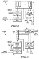
- FIG. 2 illustrates arbiter 40 of FIG. 1, in further detail.
- the arbiter includes a block 44, a master recognition unit 70, a target recognition unit 72, and a data bus grant (DBG) and DTI value generation unit 74.
- Block 44 contains multiple queues, labeled 1, 2, through n, each corresponding to devices 10, 20, ... 30 of FIG. 1.
- Each of the queues 1, 2, ... n is a copy of the queues 12, 24, ... 34 resident in the corresponding device 10, 20, ...30.
- the queue is used to keep track of transactions on address bus 60 and data bus 50. As an address is provided on the bus, an identifier is placed in the queue. This allows identification of the reordered data for each address.
- the arbiter is able to order transactions efficiently without requiring the tag information be placed with the address.
- the arbiter uses a data transaction index (DTI) during a data tenure.
- the DTI acts as a pointer into the queue of outstanding data transactions for a given master or slave.
- the information in the queue indicates which transaction is to be served by the subsequent data tenure.
- a small DTI value indicates an older transaction, i.e. one that has been pending for a while; similarly a large DTI value indicates a more recent transaction.
- DBG data bus grant
- arbiter 40 Also included in arbiter 40 is master recognition unit 70 and target recognition unit 72, each coupled to block 44.
- each of the devices coupled to the split bus monitor the bus for transactions having one of their addresses, i.e. targets the device. If a device detects that it is the target of a transaction, the device sends a target indication signal to target recognition unit 72.
- Target recognition unit 72 then provides the transaction target information to block 44 to identify the targeted device and its corresponding queue in unit 44. For example, device 10 corresponds to queue 1 of block 44.
- device 10 When device 10 is the targeted device, device 10 will provide a target indication signal to arbiter 40. Upon receipt of the target indication signal from device 10, target recognition unit 72 will provide information to block 44 which selects queue 1, the queue corresponding to device 10.
- the master recognition unit 70 identifies a needed data transaction due to an address tenure performed by a master. Master recognition unit 70 is coupled to address bus 60, from which it receives address information corresponding to transactions to be performed on data bus 50. Address information includes the address of the data access, and also may include information regarding the type of transactions, such as size of data accessed, etc. Master recognition unit 70 provides transaction information received from address bus 60 to block 44. The information from master recognition unit 70 is used to provide the contents of the selected queue.
- Arbiter 40 also includes DBG and DTI value generation unit 74, which is bi-directionally coupled to block 44.
- DBG and DTI value generation unit 74 generates individual data bus grant signals, DBG1, DBG2, through DBGn, and also generates a DTI value which is provided to each of the devices coupled to the bus. For a given transaction DBG and DTI value generation unit 74 determines which transaction indicator from which queue in block 44 corresponds to the next transaction. The DTI value corresponding to this next transaction is driven with the appropriate DBG to perform that transaction's data tenure.
- FIG. 3 illustrates, in detailed form, device 10 of FIG. 1.
- Device 10 includes a master control unit 90, a target determination unit 92, a DBG and DTI value recognition unit 94, and a data transaction queue (DTQ) 12.
- Data transfer unit 96 is bidirectionally coupled to data bus 50 from which data transfer unit 96 receives data and transaction information.
- Data transfer unit 96 is also bi-directionally coupled to data transaction queue (DTQ) 12.
- DTQ 12 contains entries indexed from 0 to m. Each of the entries represents a master or slave transaction which has been provided to arbiter 40.
- Data transfer unit 96 stores the data transaction information in DTQ 12 and performs the functions required during a data tenure.
- DBG and DTI value recognition unit 94 receives the individual data bus grant signal DBG1 and the DTI value from arbiter 40. Note that according to one embodiment, the DTI signals are broadcast to all devices on the bus, where as DBG1 is only signalled to device 10. In alternate embodiments each device may have dedicated DTI signals from arbiter 40 that are not connected to any other device in the system. DBG and DTI value recognition unit 94 then provides information to DTQ 12 for selection of an entry within DTQ 12 corresponding to a next transaction.
- Master control unit 90 is bi-directionally coupled to address bus 60 where transaction information is provided by master control unit 90. Master control unit 90 is coupled to DTQ 12 and provides transaction information for device 10 to DTQ 12. Target determination unit 92 is also bi-directionally coupled to address bus 60. Target determination unit 92 uses address information received from address bus 60 to determine when to assert a target indicator. When device 10 detects that it is the target of a transaction, target determination unit 92 provides a target indication identifying itself to arbiter 40. Device 10 snoops the bus for any transactions involving its address(es).
- FIG. 4 illustrates, in timing diagram form, operation of data processing system 5 of FIG. 1.
- the horizontal axis represents time where time divisions are made at t1, t2, t3, t4, t5, t6, and t7.
- the vertical axis is used to indicate binary voltage levels of various signals within data processing system 5.
- Below each of the specified time periods is an exemplar of the queue resident in device 10. The state of the queue is at the end of the cycle. This information provides the state of DTQ 12 during each time period.
- Address information is provided on address bus 60 where during a first time period from 0 to t1, address A0 is active on the bus. Address A0 is provided from one of the devices resident on the bus.
- the vertical axis also illustrates the data bus grant signal, the data transaction index (DTI) and the data signal. Data is provided on data bus 50.
- address A0 is active on the address bus and, as illustrated in the queue provided below time period t1, A0 provides information which is stored in the Q0 entry of DTQ 12.
- DTQ 12 does not store the entire information broadcast as address A0, but stores an indication of the transaction corresponding to address A0.
- address A1 is active on the address bus.
- DTQ 12 has an address indicator corresponding to address A1 stored in entry Q1 of the queue. Note that entry Q0 of DTQ 12 remains A0.
- address A2 is active on the address bus.
- the state of DTQ 12 at time t3 has a transaction indicator corresponding to address A2 in entry Q2, a transaction indicator corresponding to A1 in entry Q1, and a transaction indicator corresponding to A0 in entry Q0.
- the data grant is provided to device 10.
- the DTI provided by arbiter 40 has a value of 1, which corresponds to the Q1 entry in DTQ 12. This results in DATA1 being provided on the data bus between t4 and time t5. DATA1 corresponds to address A1.
- the transaction indicator corresponding to A1 is removed from the queue and the transaction indicator corresponding to A2 moves into the entry Q1 of the queue. Similarly, the transaction indicator corresponding to A0 is in entry Q0. Also during this time period, the data bus grant signal, DBG1, is provided to device 10. Note that once again the DTI has a value of 1, which corresponds to the Q1 entry in DTQ 12.
- DATA2 is provided on the data bus 50.
- DATA2 corresponds to address A2, which is in entry Q1 of the queue.
- the queue is updated as A2 is removed from position Q1 and the only remaining entry is the indicator corresponding to A0 which is an entry Q0 of the queue.
- the grant signal is once again asserted to device 10, and the DTI is provided at a value of 0.
- the grant signal is not asserted to device 10, therefore, device 10 is not responsive to the DTI value generated on the system.
- the DATA0 corresponding to the DTI for the last cycle is provided on the bus. Note that the provision of data lags the assertion of the grant signal by one cycle in FIG. 4. In alternate embodiments, the data lags assertion of the data bus grant signal by any amount of time. Here for the time period t6-t7 there are no transaction indicators stored in the queue of device 10.
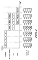
- FIG. 5 illustrates, in time and diagram form, an example of the operation of data processing system 5 according to one embodiment of the present invention.
- device 10 and device 20 are involved in at least one transaction.
- FIG. 5 has a horizontal axis representing time, including time periods indicated by t1, t2, t3, t4, t5, t6, t7, and t8.
- the vertical axis represents the various signals within data processing system 5.
- Signals include device 10 mastering the address, where address information is provided by device 10 on address bus 60.
- the signals also include device 20 mastering the address, which indicates the address information provided by device 20 on address bus 60.
- DBG1 and DBG2 are also included in the signals illustrated in FIG. 5.
- DBG1 is the data bus grant signal provided by arbiter 40 to device 10
- DBG2 is the data bus grant signal provided from arbiter 40 to device 20.
- data transaction index information (DTI) is also indicated in FIG. 5. Note that according to one embodiment, DTI is provided by arbiter 40 to all devices within the system.
- DATA is illustrated, which indicates the data information active on data bus 50.
- two queues are illustrated.
- the first queue located on the left side, represents DTQ 12 which is the data transaction queue of device 10.
- the second queue located on the right side, represents DTQ 22, which is the data transaction queue of device 20.
- DTQ 12 has a transaction indicator corresponding to address A0 in the entry Q0 with all other entries empty.
- DTQ 24 has all entries empty.
- device 10 is the master and it is providing address information corresponding to address A0 on the address bus 60.
- the address A0 indicates a specific transaction which is to be performed, where a transaction indicator is information stored in DTQ 12.
- the transaction indicator typically includes an address plus a transaction type.
- the transaction type may be a read, a write, or a read with intent to modify. Alternate embodiments may include the number of bytes to transfer in a burst type transaction or transaction size.
- device 10 again is master of the address bus and this time provides address A1 on the address bus 60.
- Address A1 also has a corresponding transaction, where transaction information corresponding to address A1 is stored in DTQ 12 at entry Q1.
- device 20 is snooping the address bus to monitor for a transaction in which it is involved. Also during this time period, device 20 determines that it is a target of the transaction indicated by address A1, and therefore assets its target indicator to arbiter 40. In this way device 20 acknowledges to arbiter 40 that it is the target device involved in this transaction.
- Device 20 may be a sink or a source in this transaction. Note that this indicates to arbiter 40 that transaction indication information associated with address A1 is to be stored not only in DTQ 12 but also in DTQ 24 which is the data transaction queue of device 20.
- device 20 is now master of the address bus for the transaction associated with address A2.
- Device 2 provides address A2 on address bus 60.
- device 10 is snooping the address bus and discovers that it is to be the target of the transaction indicated by address A2.
- device 10 asserts its target indicator to arbiter 40.
- DTQ 12 contains a transaction indicator corresponding to address A2 in entry Q2, a transaction indicator corresponding to address A1 in entry Q1, and an address indicator corresponding to address A0 in entry Q0.
- DTQ 24 includes a transaction indicator corresponding to address A2 in entry Q1 and corresponding to address A1 in entry Q0.
- arbiter 40 asserts the data bus grant signal DBG1 which grants the data bus to device 10, indicating that device 10 will be involved in the next transaction.
- the DTI signal is provided at a value of 1, indicating the transaction in entry 1 of DTQ 12 will be the next data transaction.
- the information in entry 1 of DTQ 12 indicates that the next transaction will involve data corresponding to address A1.
- Device 10 may provide the data corresponding to address A1 or it may receive the data corresponding to address A1.
- the transaction identifier provides information on whether device 10 will be a source or a sink for this transaction. In this case device 10 will sourcing the data, but since transaction indicators corresponding to address A1 are located at different positions in DTQ 12 and DTQ 24, it is necessary to grant the data bus to the source and to the sink in different cycles.
- the arbiter 40 asserts DBG2 to device 20 which grants the data bus to device 20.
- device 10 is the source and device 20 is the sink, but it is possible in a similar transaction for device 10 to be the sink and device 20 to be the source.
- the order of provision of DBG1 and DBG2 does not necessarily indicate which is a source and which is a sink.
- arbiter 40 provides DBG2 to device 20.
- DTI is provided at a value of 0. This is necessary as address A1 is in entry 0 of DTQ 24 which corresponds to DBG2. In this way provision of the data bus grant signal coupled with the value of the DTI provides an indication of the transaction indicator to be used for each device.
- DATA1 which corresponds to the transaction corresponding to address A1 is provided on data bus 50.
- DBG2 is provided by arbiter 40 to device20, and DTI is provided by arbiter 40 at a value of 0. This indicates that the next transaction corresponds to address A2.
- DTQ 12 contains a transaction indicator corresponding to address A2 in entry Q1 and address A0 in entry Q0.
- DTQ 24 contains a transaction indicator corresponding to address A2 in entry Q0.
- arbiter 40 asserts DBG1 granting the data bus to device 10.
- DTI is provided at a value of 1. This indicates that the first entry in DTQ 12 represents the transaction.
- the transaction corresponds to address A2.
- DATA2 which corresponds to address A2 is provided on data bus 50.
- the state of the DTQ 12 has entries Q1 through Q 3 empty and a transaction indicator corresponding to address A0 is contained in entry Q0. All entries of DTQ 24 are empty.
- arbiter 40 Operation of arbiter 40 is further illustrated in FIG. 6, where a flow chart is used to track operation of each module within arbiter 40.
- FIG. 6 illustrates the operation of master recognition unit 70.
- process flow begins with decision diamond 100, where it is determined if a new transaction has been detected. Note that in the notation used in FIGs. 6-11 a transaction is indicated as "XN". Proceeding from decision diamond 100, if a new transaction is not detected, process flow returns to decision diamond 100 to continue to monitor for a new transaction. If a new transaction is detected process flow continues to block 102.
- Process flow continues to block 104, where transaction information is placed into a copy of the queue corresponding to device X.
- the copy of the queue corresponding to device X is resident in block 44 of arbiter 40 of data processing system 5, as illustrated in FIGs. 1 and 2.
- Process flow continues to block 106 to start monitoring for a target indicator for the current transaction. The monitoring is performed by target recognition unit 72.
- Master recognition unit 70 provides information to target recognition unit 72 to initiate monitoring address bus 60.
- Process flow within master recognition unit 70 then continues back to decision diamond 100 to wait for a next transaction.
- Block 106 initiates operation of target recognition unit 72, starting at block 110.
- Process flow continues to decision diamond 112 where it is determined if a target indicator has been detected for this transaction. If no indicator is detected process flow returns to decision diamond 112. If the target indicator is detected, process flow continues to block 114, where the target device "Y" is identified for this transaction based on the target indicator information.
- Process flow continues to block 116 where a transaction identifier corresponding to the transaction is also placed into a copy of device Y's queue, resident in arbiter 40. Note that the queue corresponding to device Y is contained within the multiple queues of block 44 illustrated in FIG. 2. Once the transition identifier has been stored into the copy of Y's queue, process flow for target recognition unit 72 is complete.
- FIG. 8 illustrates the operation of DBG and DTI value generation unit 74.
- Process flow begins at block 120 to search all of the data transaction queues (DTQs) contained in block 44 of arbiter 40.
- Block 44 is searched to find a priority transaction which is to be performed next. This may be a highest priority, or may be selected according to some other priority scheme. Typically the selection of a next transaction is based on the considerations of maximizing utilization of the data bus. In this way transactions which require long latency on the data bus are reordered such that those latency periods are filled with the transfer of data for out of order transactions.
- Process flow then continues to block 122, to determine a data transaction index (DTI) value "A" corresponding to data source device X for this transaction and DTI value "B" corresponding to data sink device Y for this transaction.
- DTI data transaction index
- device X will provide the data
- device Y will receive the data.
- the indication of source and sink is not an indication of master and/or slave, but rather indicates direction of data flow within data processing system 5.
- the sink and source indication is contained in the transaction indicator which is stored in the DTQs.
- the DTI value according to one embodiment of the present invention is the position in the respective queues. Therefore the DTI value for device X will be the position of the transaction indicator for this transaction within the copy of the queue corresponding to device X. Similarly the DTI value for device Y will be the position in the copy of the queue corresponding to device Y where the transaction indicator corresponding to this transaction is stored.
- process flow continues to block 126 where the DTI value is provided to data bus 50 on the DTI conductors.
- Process flow then continues to block 13 where arbiter 40 simultaneously grants the data bus to device X and to device Y. This is done by simultaneously asserting the DBG signals going to devices X and Y.
- Data flow then continues to block 134.
- the transaction indicators corresponding to this transaction are then removed from each from the associated queues within block 44 of arbiter 40.
- Process flow then returns to block 120 to search the queues of block 44 for the next priority transaction.
- process flow continues to block 128.
- the transaction index corresponding to this transaction for device X is provided to data bus 50 on the DTI conductors. In this way, the DTI value is broadcast within data processing system 5.
- one DBG signal is provided to device X. No bus grant signal is provided to device Y at this time.
- Process flow then continues to block 132, where at a subsequent time, the DTI value corresponding to the transaction for device Y is provided on data bus 50 and at the same time, the DBG signal for device Y is provided to device Y.
- the DTI and DBG combination indicates the position of the transaction indicator in device X's DTQ.
- the DBG and DTI combination provides information about the position of the transaction indicator in device Y's DTQ. This is necessary as block 44 of arbiter 40 contains copies of the queues that are resident in each of the devices. For a given transaction, where the position of the transaction indicator is different for the DTQs of device X and device Y, it is not sufficient to provide the position of only one. Rather, the position of the transaction indicator in the DTQs of device X and device Y is determined to affect the transaction. By time shifting this information, each device is able to locate the transaction indicator when it receives a data bus grant signal.
- each device has an individual data bus grant signal.
- each device receives its own DTI signal from the arbiter, it is possible to issue DBG and DTI signals to both devices involved in the transaction simultaneously, even if the DTIs are not the same.
- the processing flow continues to block 134.
- the transaction indicators corresponding to this transaction are then removed from each from the associated DTQs within block 44 of arbiter 40.
- Process flow then returns to block 120 to search the copies of DTQs within block 44 for the next priority transaction.
- Device 10 is illustrated in detail. The operation of device 10 is illustrated in FIG. 9.
- Device 10 includes master control unit 90, target determination unit 92, and DBG and DTI value recognition unit 94.
- Processing flow begins at decision diamond 200 to determine if this device is mastering a new transaction. This decision determines if device 10 will be providing information on address bus 60. If this device is not mastering an address tenure, the process flow returns to decision diamond 200. If this device is the master, process flow continues to block 202 where address values are placed on address bus 60. Process flow then continues to block 204 where a transaction identifier is placed into the first available entry, or tail, of the data transaction queue 12. The master adds a new transaction to the tail of its DTQ with each transaction start for a transaction that requires a data tenure. The process flow then returns to decision diamond 200.
- FIG. 10 illustrates the process flow of target determination unit 92 within device 10.
- process flow begins at block 206 where device 10 snoops address bus 60. The snooping is done to determine if device 10 is the target of any transaction which is being specified on address bus 60. The process flow then continues to decision diamond 208 to determine if device 10 is a target of a transaction. If it is not a target, process flow returns to block 206 to continue snooping. If the device is a target of a transaction, process flow continues block 210, where the target indicator is asserted providing an indication to arbiter 40 that this device is to be involved in the next transaction.
- arbiter 40 When arbiter 40 receives the target indicator, it knows to store transaction indicator information in the queue associated with this device Process flow then continues to block 212, where a transaction identifier is placed into the first available entry in the DTQ of the device. The process flow then continues by returning to block 206.
- FIG. 11 illustrates operation of DBG and DTI value recognition unit of device 10.
- process flow begins at decision diamond 214 to determine if the DBG signal has been provided for this device. If the data bus grant has not been received, process flow returns to decision diamond 214. If the DBG signal has been received, process flow continues to block 216. Here the DTI signal value is used to select a transaction identifier from the data transaction queue 12. Process flow then continues to block 218 to remove the transaction identifier from DTQ 12 and update DTQ 12. The process flow then returns to decision diamond 214.
- the present invention allows for reordering of data transactions on a split communication bus, while eliminating the requirement of including tag information with the address portion of the transaction. This allows for full out-of-order data transfers by using an age-based data transaction index. This index is only used during a data tenure. The maximum number of pending transactions allowed will determine the minimum size of the index.
- a data transaction index is used to locate the position in the queue of the next transaction; the data transaction index is broadcast to all devices in the system.
- Individual data bus grant signals are provided to each device in order to distinguish between them.
- One embodiment of the present invention provides different transaction information to the source and sink devices of a single transaction using only one set of signals to both devices. This is accomplished by time multiplexing the information to the devices. This coordinates the states of each device and provides the advantage of using only one set o bussed signals to generate multiple transaction information for the same transaction.
Landscapes
- Engineering & Computer Science (AREA)
- Theoretical Computer Science (AREA)
- Physics & Mathematics (AREA)
- General Engineering & Computer Science (AREA)
- General Physics & Mathematics (AREA)
- Computer Hardware Design (AREA)
- Software Systems (AREA)
- Bus Control (AREA)
- Small-Scale Networks (AREA)
- Information Retrieval, Db Structures And Fs Structures Therefor (AREA)
Abstract
Description
Claims (10)
- A method of performing transactions in a data processing system:receiving a plurality of transaction indicators representing a plurality of transactions;assigning a unique transaction index value to each of the plurality of transaction indicators;executing a first one of the plurality of transactions, wherein a second one of the plurality of transactions has been pending longer than the first one of the plurality of transactions; andreassigning at least one of the unique transaction index values.
- The method of claim 1, further comprising the steps of:determining a next transaction to execute; generating a data transaction index signal based on a current unique transaction index value of the next transaction.
- A data processing system comprising:a first circuitry capable of receiving a plurality of transaction indicators representing a plurality of transactions;a second circuitry capable of assigning a unique transaction index value to each of the plurality of transaction indicators;a third circuitry capable of executing a first one of the plurality of transactions, wherein a second one of the plurality of transactions is older than the first one of the plurality of transactions; anda fourth circuitry capable of reassigning at least one of the unique transaction index values.
- The data processing system of claim 3, further comprising:a fifth circuitry capable of determining a next transaction to execute;a sixth circuitry capable of generating a data transaction index signal based on a current unique transaction index value of the next transaction.
- The data processing system of claim 3, further comprisinga seventh circuitry capable of recognizing the unique transaction index values as positions within a transaction queue.
- A data processing system comprising:a split transaction bus (50,60) having a data signal portion and a data index signal portion;a first device coupled to the split transaction bus; andan arbiter (40) coupled to the split transaction bus, comprising:a first transaction queue (1,2 ... n) corresponding to the first device (10,20 ... 30), the first transaction queue having a first position with a first transaction and a second position with a second transaction;a first circuitry (74) capable of changing the first transaction from the first position to the second position as a second transaction is executed;a second circuitry (74) capable of providing a first data bus grant signal to the first device; anda third circuitry (74) capable of providing a transaction index signal to the first device, wherein the first transaction index signal corresponds to the second position in the first transaction queue,
wherein the first device is capable of accessing the data portion of the split transaction bus in response to the first device receiving the first data bus grant signal and receiving the transaction index signal from the arbiter. - The data processing system as in claim 6, further comprising:a second device coupled to the split transaction bus; and
wherein the arbiter further comprises:a second transaction queue corresponding to the second device, the second transaction queue having a first position with a third transaction and a second position with a fourth transaction;
wherein the first circuitry is capable of changing the third transaction from the first position to the second position as the fourth transaction is executed;
wherein the second circuitry is capable of providing a second data bus grant signal to the second device;
wherein the third circuitry is capable of providing the transaction index signal to the second device;
wherein the second device is capable of accessing the data portion of the split transaction bus in response to the second device receiving the second data bus grant signal and receiving the transaction index signal from the arbiter. - A method of performing data transactions in a data processing system comprising:storing a first identifier of a first transaction and a second identifier of a second transaction into a first device queue corresponding to a first device, wherein the first identifier is stored in a first position in the first device queue and the second identifier is stored in a second position in the first device queue, wherein the first position is different from the second position;generating a first data transaction index signal and a first data bus grant signal to the first device at a first time, wherein the first data transaction index signal corresponds to the first position;reordering the first device queue such that the second identifier is moved from the second position to a third position in the first device queue, wherein the third position is different from the second position; andgenerating a second data transaction index signal and a second data bus grant signal to the second device at a second time subsequent to the first time, wherein the second data transaction index signal corresponds to the third position.
- The method of claim 8, wherein:the first device queue lies within a first device, wherein the first device is a master of the second transaction; andthe method further comprises determining that a second device is a target of the second transaction from the first device; andthe second device includes a second device queue.
- A data processing method comprising the steps of:receiving a first target indicator within an arbiter, wherein the arbiter has a first device queue and a second device queue, wherein the first target indicator identifies a first device;storing a first identifier of a first transaction into the first device queue corresponding to the first device, wherein the first identifier is stored in a first position in the first device queue;storing the first identifier of the first transaction into the second device queue corresponding to the second device, wherein the first identifier is stored in a second position in the second device queue, wherein the second position is different from the first position;generating a first data transaction index value and a first data bus grant signal to the first device at a first time; andgenerating a second data transaction index value and a second data bus grant signal to the second device at a second time subsequent to the first time.
Applications Claiming Priority (2)
| Application Number | Priority Date | Filing Date | Title |
|---|---|---|---|
| US09/127,459 US6240479B1 (en) | 1998-07-31 | 1998-07-31 | Method and apparatus for transferring data on a split bus in a data processing system |
| US127459 | 1998-07-31 |
Publications (2)
| Publication Number | Publication Date |
|---|---|
| EP0981093A2 true EP0981093A2 (en) | 2000-02-23 |
| EP0981093A3 EP0981093A3 (en) | 2002-12-11 |
Family
ID=22430233
Family Applications (1)
| Application Number | Title | Priority Date | Filing Date |
|---|---|---|---|
| EP99114595A Withdrawn EP0981093A3 (en) | 1998-07-31 | 1999-07-26 | Method and apparatus for performing transactions in a data processing system |
Country Status (6)
| Country | Link |
|---|---|
| US (1) | US6240479B1 (en) |
| EP (1) | EP0981093A3 (en) |
| JP (1) | JP2000285068A (en) |
| KR (1) | KR100596947B1 (en) |
| CN (1) | CN1191521C (en) |
| TW (1) | TW518470B (en) |
Cited By (2)
| Publication number | Priority date | Publication date | Assignee | Title |
|---|---|---|---|---|
| KR20020030223A (en) * | 2000-10-16 | 2002-04-24 | 주식회사 알라딘소프트 | Logging and recovery method for supporting high performance transaction in main memory resident database system |
| US8307139B1 (en) * | 2003-03-14 | 2012-11-06 | Marvell International Ltd. | Method and apparatus for dynamically granting access of a shared resource among a plurality of requestors |
Families Citing this family (20)
| Publication number | Priority date | Publication date | Assignee | Title |
|---|---|---|---|---|
| US6816934B2 (en) * | 2000-12-22 | 2004-11-09 | Hewlett-Packard Development Company, L.P. | Computer system with registered peripheral component interconnect device for processing extended commands and attributes according to a registered peripheral component interconnect protocol |
| DE19854178A1 (en) * | 1998-11-24 | 2000-05-31 | Siemens Ag | High-scaling multiprocessor system bus e.g. for telecommunication switching centres |
| US6513084B1 (en) * | 1999-06-29 | 2003-01-28 | Microsoft Corporation | Arbitration of state changes |
| US6801954B1 (en) * | 2000-02-25 | 2004-10-05 | Hewlett-Packard Development Company, L.P. | Method and apparatus to concurrently operate on multiple data movement transactions in a disk array subsystem |
| US6594722B1 (en) * | 2000-06-29 | 2003-07-15 | Intel Corporation | Mechanism for managing multiple out-of-order packet streams in a PCI host bridge |
| US6845115B2 (en) * | 2002-12-05 | 2005-01-18 | Agilent Technologies, Inc. | Coupled resonant cavity surface-emitting laser |
| US7111001B2 (en) * | 2003-01-27 | 2006-09-19 | Seiko Epson Corporation | Event driven transaction state management with single cache for persistent framework |
| US6993619B2 (en) * | 2003-03-28 | 2006-01-31 | International Business Machines Corporation | Single request data transfer regardless of size and alignment |
| US20050091306A1 (en) | 2003-10-02 | 2005-04-28 | Charbel Khawand | Interprocessor communication protocol with high level service composition |
| US7203780B2 (en) | 2005-02-22 | 2007-04-10 | Kabushiki Kaisha Toshiba | System and method for facilitating communication between devices on a bus using tags |
| US7290074B2 (en) * | 2005-04-06 | 2007-10-30 | Kabushiki Kaisha Toshiba | Back-off timing mechanism |
| US7373444B2 (en) * | 2005-04-15 | 2008-05-13 | Kabushiki Kaisha Toshiba | Systems and methods for manipulating entries in a command buffer using tag information |
| GB2426604B (en) | 2005-05-26 | 2010-07-14 | Advanced Risc Mach Ltd | Interconnect logic for a data processing apparatus |
| US7865684B2 (en) * | 2005-06-27 | 2011-01-04 | Ab Initio Technology Llc | Managing message queues |
| CN100410884C (en) * | 2005-09-06 | 2008-08-13 | 大连海事大学 | A transaction distribution method for group cooperating processing of transactions based on the idea of PID |
| US7738483B2 (en) * | 2005-09-08 | 2010-06-15 | Kabushiki Kaisha Toshiba | Systems and methods for managing communication between master and slave devices |
| KR100873010B1 (en) | 2007-05-17 | 2008-12-09 | 한국과학기술원 | Non-blocking master, bus arbitration device, bus system and method of arbitrating a bus |
| US7613859B2 (en) * | 2007-09-12 | 2009-11-03 | Kabushiki Kaisha Toshiba | Back-off timing mechanism in a digital signal processor |
| US20100325327A1 (en) * | 2009-06-17 | 2010-12-23 | Freescale Semiconductor, Inc. | Programmable arbitration device and method therefor |
| US10255103B2 (en) * | 2017-04-04 | 2019-04-09 | Arm Limited | Transaction handling |
Citations (3)
| Publication number | Priority date | Publication date | Assignee | Title |
|---|---|---|---|---|
| EP0674272A1 (en) * | 1994-02-24 | 1995-09-27 | Hewlett-Packard Company | Queue-based predictive flow control mechanism |
| US5638538A (en) * | 1995-01-13 | 1997-06-10 | Digital Equipment Corporation | Turbotable: apparatus for directing address and commands between multiple consumers on a node coupled to a pipelined system bus |
| US5659707A (en) * | 1994-10-07 | 1997-08-19 | Industrial Technology Research Institute | Transfer labeling mechanism for multiple outstanding read requests on a split transaction bus |
Family Cites Families (11)
| Publication number | Priority date | Publication date | Assignee | Title |
|---|---|---|---|---|
| US5036456A (en) * | 1987-02-13 | 1991-07-30 | Honeywell Information Systems Inc. | Apparatus for controlling concurrent operations of a system control unit including activity register circuitry |
| US5394351A (en) * | 1994-03-11 | 1995-02-28 | Nexgen, Inc. | Optimized binary adder and comparator having an implicit constant for an input |
| US5548795A (en) * | 1994-03-28 | 1996-08-20 | Quantum Corporation | Method for determining command execution dependencies within command queue reordering process |
| US5699516A (en) | 1994-12-22 | 1997-12-16 | Motorola, Inc. | Method and apparatus for implementing a in-order termination bus protocol within a data processing system |
| US5890222A (en) * | 1995-01-04 | 1999-03-30 | International Business Machines Corporation | Method and system for addressing registers in a data processing unit in an indirect addressing mode |
| US5901295A (en) * | 1995-04-28 | 1999-05-04 | Apple Computer, Inc. | Address and data bus arbiter for pipelined transactions on a split bus |
| US5778434A (en) * | 1995-06-07 | 1998-07-07 | Seiko Epson Corporation | System and method for processing multiple requests and out of order returns |
| JPH09128325A (en) * | 1995-11-06 | 1997-05-16 | Mitsubishi Electric Corp | Hierarchical bus control system and bus bridge |
| US5790813A (en) * | 1996-01-05 | 1998-08-04 | Unisys Corporation | Pre-arbitration system allowing look-around and bypass for significant operations |
| US5805595A (en) * | 1996-10-23 | 1998-09-08 | Cisco Systems, Inc. | System and method for communicating packetized data over a channel bank |
| KR100253192B1 (en) * | 1997-09-05 | 2000-04-15 | 구자홍 | System bus control method for distributed shared memory structure |
-
1998
- 1998-07-31 US US09/127,459 patent/US6240479B1/en not_active Expired - Lifetime
-
1999
- 1999-07-26 EP EP99114595A patent/EP0981093A3/en not_active Withdrawn
- 1999-07-30 CN CNB99111910XA patent/CN1191521C/en not_active Expired - Fee Related
- 1999-07-30 JP JP11216930A patent/JP2000285068A/en active Pending
- 1999-07-31 KR KR1019990031534A patent/KR100596947B1/en active IP Right Grant
- 1999-08-17 TW TW088113011A patent/TW518470B/en not_active IP Right Cessation
Patent Citations (3)
| Publication number | Priority date | Publication date | Assignee | Title |
|---|---|---|---|---|
| EP0674272A1 (en) * | 1994-02-24 | 1995-09-27 | Hewlett-Packard Company | Queue-based predictive flow control mechanism |
| US5659707A (en) * | 1994-10-07 | 1997-08-19 | Industrial Technology Research Institute | Transfer labeling mechanism for multiple outstanding read requests on a split transaction bus |
| US5638538A (en) * | 1995-01-13 | 1997-06-10 | Digital Equipment Corporation | Turbotable: apparatus for directing address and commands between multiple consumers on a node coupled to a pipelined system bus |
Cited By (3)
| Publication number | Priority date | Publication date | Assignee | Title |
|---|---|---|---|---|
| KR20020030223A (en) * | 2000-10-16 | 2002-04-24 | 주식회사 알라딘소프트 | Logging and recovery method for supporting high performance transaction in main memory resident database system |
| US8307139B1 (en) * | 2003-03-14 | 2012-11-06 | Marvell International Ltd. | Method and apparatus for dynamically granting access of a shared resource among a plurality of requestors |
| US9037767B1 (en) | 2003-03-14 | 2015-05-19 | Marvell International Ltd. | Method and apparatus for dynamically granting access of a shared resource among a plurality of requestors |
Also Published As
| Publication number | Publication date |
|---|---|
| JP2000285068A (en) | 2000-10-13 |
| TW518470B (en) | 2003-01-21 |
| CN1191521C (en) | 2005-03-02 |
| KR100596947B1 (en) | 2006-07-07 |
| EP0981093A3 (en) | 2002-12-11 |
| KR20000012128A (en) | 2000-02-25 |
| US6240479B1 (en) | 2001-05-29 |
| CN1245920A (en) | 2000-03-01 |
Similar Documents
| Publication | Publication Date | Title |
|---|---|---|
| US6240479B1 (en) | Method and apparatus for transferring data on a split bus in a data processing system | |
| EP1839167B1 (en) | Method and apparatus of reducing transfer latency in an soc interconnect | |
| US5377332A (en) | Bus arbitration algorithm and apparatus | |
| US7461190B2 (en) | Non-blocking address switch with shallow per agent queues | |
| US5761450A (en) | Bus bridge circuit flushing buffer to a bus during one acquire/relinquish cycle by providing empty address indications | |
| US5901295A (en) | Address and data bus arbiter for pipelined transactions on a split bus | |
| KR960012357B1 (en) | Method and apparatus for arbitration based on the availability of resources | |
| US7353311B2 (en) | Method of accessing information and system therefor | |
| AU1716888A (en) | Computer systems | |
| RU2154857C2 (en) | Computer system, device and method for initialization of bus device | |
| US20060010279A1 (en) | Apparatus for use in a computer systems | |
| KR910007643B1 (en) | Apparatus and method for serving interrupts utilizing pended bus | |
| CN101520759B (en) | Transaction system with dynamic priority scheme. | |
| EP0671692B1 (en) | Fast pipelined distributed arbitration scheme | |
| CN101027656A (en) | Data processing system with bus access retraction | |
| SE519920C2 (en) | Bus transactions in computer systems | |
| US20070101032A1 (en) | Bus arbitration circuit and bus arbitration method | |
| CN101027655A (en) | Data processing system with bus access retraction | |
| US5708783A (en) | Data bus arbiter for pipelined transactions on a split bus | |
| US5815676A (en) | Address bus arbiter for pipelined transactions on a split bus | |
| JPH09269927A (en) | Bus access method, bus and bus connection system | |
| GB2341771A (en) | Address decoding | |
| JPH11232215A (en) | Bus controller, bus master device and method for controlling bus control system | |
| US20050149655A1 (en) | Bus allocation method and apparatus | |
| GB2341766A (en) | Bus architecture |
Legal Events
| Date | Code | Title | Description |
|---|---|---|---|
| PUAI | Public reference made under article 153(3) epc to a published international application that has entered the european phase |
Free format text: ORIGINAL CODE: 0009012 |
|
| AK | Designated contracting states |
Kind code of ref document: A2 Designated state(s): AT BE CH CY DE DK ES FI FR GB GR IE IT LI LU MC NL PT SE |
|
| AX | Request for extension of the european patent |
Free format text: AL;LT;LV;MK;RO;SI |
|
| RIN1 | Information on inventor provided before grant (corrected) |
Inventor name: GARCIA, MICHAEL JULIO Inventor name: REYNOLDS, BRIAN KEITH Inventor name: TODD, DAVID WILLIAM Inventor name: SYNDER, MICHAEL DEAN |
|
| PUAL | Search report despatched |
Free format text: ORIGINAL CODE: 0009013 |
|
| AK | Designated contracting states |
Kind code of ref document: A3 Designated state(s): AT BE CH CY DE DK ES FI FR GB GR IE IT LI LU MC NL PT SE |
|
| AX | Request for extension of the european patent |
Free format text: AL;LT;LV;MK;RO;SI |
|
| AKX | Designation fees paid | ||
| REG | Reference to a national code |
Ref country code: DE Ref legal event code: 8566 |
|
| STAA | Information on the status of an ep patent application or granted ep patent |
Free format text: STATUS: THE APPLICATION IS DEEMED TO BE WITHDRAWN |
|
| 18D | Application deemed to be withdrawn |
Effective date: 20030612 |