EP0968567B2 - Safety switch - Google Patents
Safety switch Download PDFInfo
- Publication number
- EP0968567B2 EP0968567B2 EP97953925A EP97953925A EP0968567B2 EP 0968567 B2 EP0968567 B2 EP 0968567B2 EP 97953925 A EP97953925 A EP 97953925A EP 97953925 A EP97953925 A EP 97953925A EP 0968567 B2 EP0968567 B2 EP 0968567B2
- Authority
- EP
- European Patent Office
- Prior art keywords
- actuator
- actuating element
- reading head
- safety switch
- code
- Prior art date
- Legal status (The legal status is an assumption and is not a legal conclusion. Google has not performed a legal analysis and makes no representation as to the accuracy of the status listed.)
- Expired - Lifetime
Links
- 238000012544 monitoring process Methods 0.000 claims abstract description 3
- 238000011156 evaluation Methods 0.000 claims description 17
- 238000004804 winding Methods 0.000 claims description 3
- 238000009434 installation Methods 0.000 claims 1
- 230000003993 interaction Effects 0.000 abstract 2
- 230000001939 inductive effect Effects 0.000 abstract 1
- 230000001681 protective effect Effects 0.000 description 8
- 239000003990 capacitor Substances 0.000 description 3
- 230000004044 response Effects 0.000 description 3
- 230000035939 shock Effects 0.000 description 2
- RYGMFSIKBFXOCR-UHFFFAOYSA-N Copper Chemical compound [Cu] RYGMFSIKBFXOCR-UHFFFAOYSA-N 0.000 description 1
- 230000005540 biological transmission Effects 0.000 description 1
- 238000004140 cleaning Methods 0.000 description 1
- 230000008878 coupling Effects 0.000 description 1
- 238000010168 coupling process Methods 0.000 description 1
- 238000005859 coupling reaction Methods 0.000 description 1
- 230000001419 dependent effect Effects 0.000 description 1
- 238000010586 diagram Methods 0.000 description 1
- 230000000694 effects Effects 0.000 description 1
- 238000005516 engineering process Methods 0.000 description 1
- 230000007613 environmental effect Effects 0.000 description 1
- 230000005284 excitation Effects 0.000 description 1
- 238000012423 maintenance Methods 0.000 description 1
- 230000007257 malfunction Effects 0.000 description 1
- 238000004519 manufacturing process Methods 0.000 description 1
- 239000000463 material Substances 0.000 description 1
- 239000002184 metal Substances 0.000 description 1
- 229910052751 metal Inorganic materials 0.000 description 1
- 238000000034 method Methods 0.000 description 1
- 230000010355 oscillation Effects 0.000 description 1
- 238000012545 processing Methods 0.000 description 1
- 229920006395 saturated elastomer Polymers 0.000 description 1
- 230000008054 signal transmission Effects 0.000 description 1
- 230000007704 transition Effects 0.000 description 1
Images

Classifications
-
- H—ELECTRICITY
- H03—ELECTRONIC CIRCUITRY
- H03K—PULSE TECHNIQUE
- H03K17/00—Electronic switching or gating, i.e. not by contact-making and –breaking
- H03K17/94—Electronic switching or gating, i.e. not by contact-making and –breaking characterised by the way in which the control signals are generated
- H03K17/945—Proximity switches
-
- F—MECHANICAL ENGINEERING; LIGHTING; HEATING; WEAPONS; BLASTING
- F16—ENGINEERING ELEMENTS AND UNITS; GENERAL MEASURES FOR PRODUCING AND MAINTAINING EFFECTIVE FUNCTIONING OF MACHINES OR INSTALLATIONS; THERMAL INSULATION IN GENERAL
- F16P—SAFETY DEVICES IN GENERAL; SAFETY DEVICES FOR PRESSES
- F16P3/00—Safety devices acting in conjunction with the control or operation of a machine; Control arrangements requiring the simultaneous use of two or more parts of the body
- F16P3/08—Safety devices acting in conjunction with the control or operation of a machine; Control arrangements requiring the simultaneous use of two or more parts of the body in connection with the locking of doors, covers, guards, or like members giving access to moving machine parts
-
- G—PHYSICS
- G05—CONTROLLING; REGULATING
- G05B—CONTROL OR REGULATING SYSTEMS IN GENERAL; FUNCTIONAL ELEMENTS OF SUCH SYSTEMS; MONITORING OR TESTING ARRANGEMENTS FOR SUCH SYSTEMS OR ELEMENTS
- G05B9/00—Safety arrangements
- G05B9/02—Safety arrangements electric
-
- H—ELECTRICITY
- H03—ELECTRONIC CIRCUITRY
- H03K—PULSE TECHNIQUE
- H03K17/00—Electronic switching or gating, i.e. not by contact-making and –breaking
- H03K17/94—Electronic switching or gating, i.e. not by contact-making and –breaking characterised by the way in which the control signals are generated
- H03K17/945—Proximity switches
- H03K17/95—Proximity switches using a magnetic detector
- H03K17/952—Proximity switches using a magnetic detector using inductive coils
- H03K17/9537—Proximity switches using a magnetic detector using inductive coils in a resonant circuit
- H03K17/9542—Proximity switches using a magnetic detector using inductive coils in a resonant circuit forming part of an oscillator
-
- H—ELECTRICITY
- H03—ELECTRONIC CIRCUITRY
- H03K—PULSE TECHNIQUE
- H03K2217/00—Indexing scheme related to electronic switching or gating, i.e. not by contact-making or -breaking covered by H03K17/00
- H03K2217/94—Indexing scheme related to electronic switching or gating, i.e. not by contact-making or -breaking covered by H03K17/00 characterised by the way in which the control signal is generated
- H03K2217/945—Proximity switches
- H03K2217/95—Proximity switches using a magnetic detector
- H03K2217/958—Proximity switches using a magnetic detector involving transponders
Definitions
- the invention relates to a safety switch.
- Safety switches are used to monitor moving safety devices, such as doors and covers on machines and systems.
- the protective devices separate man and machine for mutual protection. To do this, the safety switches must safely interrupt one or more circuits when opening and keep them open until the protective device is closed again.
- electromechanical safety switches have a switching element connected to the fixed part of the protective device, into which a separate actuator connected to the movable safety device can be inserted. In this case, the separate actuator closes the switch contacts in the inserted state, while open guard, ie without an inserted actuator, the switch contacts are forcibly opened by a positive power transmission.
- actuators are used with a plurality of permanent magnets, which cooperate contactlessly with read heads in which coils are provided. For safety reasons, at least three magnets must be provided. Compared to the electromechanical safety switch, the magnetic safety switches are much more sensitive to shocks. Moreover, in the event of failure, the preferred response is that the switch does not open.
- the EP 0 229 247 A2 shows a non-contact signal generator for outputting a signal with sufficient approximation of a second part to a first part having a first transmitting means for a basic signal and a second receiving means for receiving a first signal, the second part provided for receiving the basic signal with a first receiving means is of which in response to the basic signal, a signal generating means for generating the first signal and a second signal, which can be impressed on the first signal, can be acted upon, and the signal generating means is connected downstream of a second transmitting device whose signal from the second receiving device in the first part can be received is.
- the second signal can be used to identify a specific second part, in particular comprise a characteristic value which can be mechanically coded in an adjustable manner.
- the invention is therefore an object of the invention to improve a safety switch of the type mentioned. This object is achieved by the features of claim 1.
- Advantageous embodiments are the subject of the dependent claims.
- an inductance offers greater security than the three permanent magnets. Due to the relatively large permissible mechanical tolerances between the actuator element and the reading head, use of the safety switch according to the invention is also possible on heavy safety doors.
- the read head also has an inductance which cooperates via an alternating magnetic field with the inductance of the actuator element.
- the two inductors then form a transformer.
- This transformer can be operated with the safety principle of dynamic signal transmission. This allows working with a single-channel structure even with very high security requirements. This simplifies and reduces the cost of manufacturing the reading head.
- the actuator element takes its energy to operate this magnetic alternating field, because then no separate power supply for the actuator element is necessary.
- the likelihood of a technical failure of the inductance (with the result of a transition of the safety switch in the open state) is greatly reduced, and thus the corresponding maintenance of the actuator.
- the actuator element contains in a memory an electronic coding which uniquely identifies the actuator element.
- each actuator element is unique, which manipulations of the safety switch are excluded by means of another actuator element.
- a digital evaluation is possible instead of an analog evaluation over a frequency shift.
- Similar actuator elements are used for identification systems in which moving tools or workpiece pallets carry such an actuator element which is scanned by read-write heads and optionally reprogrammed to provide instructions to a machine for the movement or transport of these parts.
- the read head is followed by an evaluation device which contains an electronic coding in at least one further memory which uniquely identifies the read head or the switching element.
- every safety switch is unique.
- a comparison device is provided in the evaluation, which compares the output from the actuator element coding with the self-stored coding.
- the coding is emitted from the actuator element upon the excitation of the reading head and received by the latter.
- Similar systems called transponders can also be used for electronic immobilizers of automobiles, for example in connection with ignition keys.
- the flow of information in the evaluation device is two-channel. This is achieved by virtue of the fact that the parts of the evaluation device which are responsible for the evaluation of the signal recorded by the read head are present at least twice.
- the safety switch may include a key-type actuator which is insertable into the housing of the switching member.
- An application of the invention is when the actuator element is provided on the actuator, while correspondingly the read head is provided within the housing of the switching element. Conceivable, however, would also be a reversed arrangement.
- the actuator can be locked by a plunger.
- a further application of the invention therefore results when the actuator element is provided on this plunger, while the read head is arranged within the housing of the switching element. Again, the arrangements could be reversed accordingly.
- the actuator is not made of metal, but made of plastic.
- Advantageous protection against malfunction due to breakage of the actuator results when winding of the inductance of the actuator element extends over almost the entire length of the actuator.
- An inventive safety switch consists of a switching element 1 with a housing 3, which is connectable to the fixed part of a protective device.
- the housing 3 is penetrated in the head area by an actuator channel 5, which is open at both ends.
- a key-like actuator 7 is inserted, which can be fastened to the movable part of a protective device, for example on a door or hood.
- the actuator 7 carries a plastic encapsulated actuator element 9 which is located within the actuator channel 5 when the actuator 7 is fully inserted into the actuator channel 5.
- the switching element 1 has a read head 11 on the edge of the actuator channel 5. When fully inserted actuator 7, the actuator element 9 and the read head 11 are arranged opposite to each other and can interact with each other.
- the reading head 11 is connected to an evaluation device 13.
- the evaluation device 13 has connections 15 to which a device supply voltage of 24 V is applied. With these terminals 15, the inputs of a regulator 17 are connected. The output of the regulator 17 outputs an internal supply voltage of 5V.
- the first microprocessor 23 is additionally monitored by the controller 17 via a control line. An output of the first microprocessor 23 is connected via an amplifier to the bases of the transistors 19 and 21.
- This coil 27 is disposed within the read head 11 on the actuator channel 5 side facing and extends with its longitudinal axis parallel to this.
- the coil 27 is a capacitor 29 connected downstream, which is on the one hand via two resistors 31 to ground, and on the other hand connected via a receiving amplifier 33 with band-pass filter to one input of the two microprocessors 23 and 25.
- a level monitor 35 is connected in parallel to each of the two resistors 31, one of which is connected to an input of the first microprocessor 23 and the other to an input of the second microprocessor 25.
- the first microprocessor 23 generates from the computer clock a frequency of 125 kHz, with which it drives the two transistors 19 and 21, which switch alternately from the locked to the saturated state.
- the existing of the coil 27 and the capacitor 29 resonant circuit whose resonant frequency is also 125 kHz, excited to vibrate.
- the coil 27 radiates a magnetic alternating field.
- the resistors 31 limit the current in the resonant circuit and thus the amplitude of the alternating magnetic field.
- the distance between actuator element 9 and read head 11 is determined, in which both can still cooperate. Since the resistors 31 are present in duplicate, the level monitors 35 can by comparison drift one of the resistors 31 detect.
- an actuator coil 37 is provided as an inductance, which is arranged on the reading head 11 facing side in the longitudinal direction of the actuator 7.
- the actuator coil 37 together with an actuator capacitor 39 forms a resonant circuit, to which an IC module 41 is connected in parallel.
- the coil 27 and the actuator coil 37 form a transformer, that is, a transformer. Since there is a gap between the two coils 27, 37, the transformer has a low degree of coupling (typically between 0.01 and 0.1).
- the magnetic alternating field radiated by the coil 27 induces a voltage in the actuator coil 37 and thus excites oscillation in the oscillating circuit 37, 39.
- the IC module 41 has a rectifier, whereby it can take the oscillating circuit 37, 39 energy. Furthermore, the IC module 41 has an EEPROM which stores a 32-bit code with which the actuator element 9 can be uniquely identified. The IC module 41 modulates with this code the amplitude in the resonant circuit 37, 39 at a rate of 1 bit per msec.
- the actuator coil 37 couples back to the coil 27 in the read head 11, whereby its resonant circuit 37, 39 is also modulated. Via the receiving amplifier 33, this modulated signal is supplied to the microprocessors 23 and 25.
- Each of the two microprocessors 23 and 25 has an EEPROM 43, in which a 32-bit code is stored, with which the read head 11 is uniquely identifiable.
- the two microprocessors 23 and 25 determine independently whether a code is ever transmitted from the actuator element 9, and whether this fits to that code from the EEPROM 23, that is, whether the associated pair of actuator element 9 and read head 11 is opposite. Only in the latter case, the microprocessor 23 or 25 via an amplifier to a relay 45, the signal to close a switch 47. For greater security while closing the switch 47 positively driven ⁇ ffnerAuthe and lines are provided with which each microprocessor 23 and 25 the Switching state of the respective other relay 45 can determine.
- the two switches 47 constitute the outputs of the safety switch and are used, for example, connected in series to control the voltage supply of the machine provided with the protective device. If the distance between actuator element 9 and read head 11 is too large, for example, with actuator 7 not inserted into actuator channel 5 (ie, an opened protection device), microprocessors 23, 25 can not detect appropriate codes, so that they receive the signal to open the switches 47 and thus to switch off the power supply of the machine.
- the switching element 1 has a displaceable in the longitudinal direction of the housing 3 plunger 51, which is preferably designed as an armature of a lifting magnet.
- the plunger 51 can traverse the perpendicular to its direction of movement actuator channel 5 and engage on the opposite side in a recess of the housing 3.
- the actuator 7 has an opening 53 through which the plunger 51 can engage when the actuator 7 is fully inserted into the actuator channel 5.
- the plunger 51 is spring-loaded against the stroke direction of the magnet.
- the arrangement and the control of the solenoid is chosen so that engages fully inserted into the actuator channel 5 actuator 7 of the plunger 51 engages under the opening 53 in the recess in the head of the housing 3 and the actuator 7 locked.
- the plunger 51 does not release the actuator 7 after switching off the machine until the machine has come to a standstill, so that it is prevented that the protective device can already be opened during the run-out of the machine.
- this has a further actuator element 55, which is designed like the actuator element 9.
- the switching element 1 in the housing 3 a further read head 57 which is formed as the read head 11.
- the further actuator element 55 and the further read head 57 are arranged so that they face each other when the plunger 51 locks the actuator 7.
- the further read-out device 57 connected downstream of the further read head has two switches, which are preferably connected in series with the switches 47 of the evaluation device 13.
- the actuator 7 is made of plastic. At the end facing away from the opening 53 mounting holes are provided with which the actuator 7 is attached to the movable part of the protective device. A turn of the actuator coil 37 consisting of copper wire is guided out of the actuator element 9, on the actuator 7, around the fastening holes 59 and back to the actuator element 9. The winding can also be placed around the opening 53. In case of breakage of the actuator 7, this turn and thus the actuator coil 37 is broken, so that the actuator element 9 can no longer respond to the alternating magnetic field of the read head 11. In this case, the switching member 1 is signaled an open protection device, so that the safety switch goes into the safe state, so the power supply of the machine shuts off.
Abstract
Description
Die Erfindung betrifft einen Sicherheitsschalter.The invention relates to a safety switch.
Mit Sicherheitsschaltern werden bewegliche Schutzeinrichtungen überwacht, beispielsweise Türen und Abdeckungen an Maschinen und Anlagen. Die Schutzeinrichtungen trennen Mensch und Maschine zum gegenseitigen Schutz voreinander. Hierzu müssen die Sicherheitsschalter beim Öffnen einen oder mehrere Stromkreise sicher unterbrechen und solange offenhalten, bis die Schutzeinrichtung wieder geschlossen wird. Elektromechanische Sicherheitsschalter weisen hierfür ein mit dem feststehenden Teil der Schutzeinrichtung verbundenes Schaltglied auf, in welches ein mit der beweglichen Schutzeinrichtung verbundener, separater Betätiger einführbar ist. Dabei schließt der separate Betätiger im eingeführten Zustand die Schalterkontakte, während bei offener Schutzeinrichtung, also ohne eingeführten Betätiger, die Schalterkontakte durch eine formschlüssige Kraftübertragung zwangsweise geöffnet sind. In Anwendungsfällen, in denen aus extremen hygienischen oder anderen Umgebungsbedingungen keine elektromechanischen Sicherheitsschalter eingesetzt werden können (Lebensmittelverarbeitung, Reinigungsanlagen), werden Betätiger mit mehreren Permanentmagneten eingesetzt, welche berührungslos mit Leseköpfen zusammenwirken, in denen Spulen vorgesehen sind. Aus Sicherheitsgründen müssen dabei mindestens drei Magnete vorgesehen sein. Gegenüber dem elektromechanischen Sicherheitsschalter sind die Magnet-Sicherheitsschalter wesentlich empfindlicher für Erschütterungen. Darüber hinaus ist bei einem Ausfall die bevorzugte Reaktion, daß der Schalter sich nicht öffnet.Safety switches are used to monitor moving safety devices, such as doors and covers on machines and systems. The protective devices separate man and machine for mutual protection. To do this, the safety switches must safely interrupt one or more circuits when opening and keep them open until the protective device is closed again. For this purpose, electromechanical safety switches have a switching element connected to the fixed part of the protective device, into which a separate actuator connected to the movable safety device can be inserted. In this case, the separate actuator closes the switch contacts in the inserted state, while open guard, ie without an inserted actuator, the switch contacts are forcibly opened by a positive power transmission. In applications in which no electro-mechanical safety switches can be used in extreme hygienic or other environmental conditions (food processing, cleaning systems), actuators are used with a plurality of permanent magnets, which cooperate contactlessly with read heads in which coils are provided. For safety reasons, at least three magnets must be provided. Compared to the electromechanical safety switch, the magnetic safety switches are much more sensitive to shocks. Moreover, in the event of failure, the preferred response is that the switch does not open.
Die
Der Erfindung liegt daher die Aufgabe zugrunde, einen Sicherheitsschalter der eingangs genannten Art zu verbessern. Diese Aufgabe wird erfindungsgemäß gelöst durch die Merkmale des Anspruches 1. Vorteilhafte Ausgestaltungen sind Gegenstand der Unteransprüche.The invention is therefore an object of the invention to improve a safety switch of the type mentioned. This object is achieved by the features of claim 1. Advantageous embodiments are the subject of the dependent claims.
Dadurch, daß das Betätigerelement für das Zusammenwirken mit dem Lesekopf eine Induktivität aufweist, sind keinerlei Permanentmagneten im Betätiger mehr notwendig. Dadurch wird der Sicherheitsschalter unempfindlich gegenüber Erschütterungen. Gleichzeitig entfällt auch das Problem, daß die Magnete einen inhomogenen Ansprechbereich haben, was sich beim seitlichen Anfahren als störend auswirkt. Da bei einem Ausfall der Induktivität der Lesekopf kein Vorhandensein eines Betätigerelementes feststellen kann, geht der Sicherheitsschalter dann in den sicheren, also geöffneten Zustand über.Characterized in that the actuator element for interacting with the read head has an inductance, no permanent magnets in the actuator are more necessary. This makes the safety switch insensitive to shocks. At the same time eliminates the problem that the magnets have an inhomogeneous response, which has a disturbing effect when starting sideways. Since in the case of failure of the inductance of the read head can not detect the presence of an actuator element, the safety switch then goes into the safe, ie open state.
Damit bietet eine Induktivität eine größere Sicherheit als die drei Permanentmagneten. Durch die relativ großen zulässigen mechanischen Toleranzen zwischen Betätigerelement und Lesekopf ist ein Einsatz des erfindungsgemäßen Sicherheitsschalters auch an schweren Schutztüren möglich.Thus, an inductance offers greater security than the three permanent magnets. Due to the relatively large permissible mechanical tolerances between the actuator element and the reading head, use of the safety switch according to the invention is also possible on heavy safety doors.
Vorteilhafterweise weist der Lesekopf ebenfalls eine Induktivität auf, welche über ein magnetisches Wechselfeld mit der Induktivität des Betätigerelementes zusammenwirkt. Die beiden Induktivitäten bilden dann einen Transformator. Dieser Transformator kann mit dem sicherheitstechnischen Prinzip der dynamischen Signalübertragung betrieben werden. Dieses erlaubt, auch bei sehr hohen Sicherheitsanforderungen mit einer einkanaligen Struktur zu arbeiten. Damit vereinfacht und verbilligt sich die Herstellung des Lesekopfes.Advantageously, the read head also has an inductance which cooperates via an alternating magnetic field with the inductance of the actuator element. The two inductors then form a transformer. This transformer can be operated with the safety principle of dynamic signal transmission. This allows working with a single-channel structure even with very high security requirements. This simplifies and reduces the cost of manufacturing the reading head.
Besonders vorteilhaft ist, daß das Betätigerelement seine Energie zum Betrieb diesem magnetischen Wechselfeld entnimmt, weil dann keine eigene Spannungsversorgung für das Betätigerelement notwendig ist. Damit wird die Wahrscheinlichkeit eines technischen Ausfalls der Induktivität (mit der Folge eines Übergangs des Sicherheitsschalters in den geöffneten Zustand) stark vermindert, und dadurch auch der entsprechende Wartungsaufwand des Betätigers.It is particularly advantageous that the actuator element takes its energy to operate this magnetic alternating field, because then no separate power supply for the actuator element is necessary. Thus, the likelihood of a technical failure of the inductance (with the result of a transition of the safety switch in the open state) is greatly reduced, and thus the corresponding maintenance of the actuator.
Gemäß der Erfindung enthält das Betätigerelement in einem Speicher eine elektronische Codierung, welche das Betätigerelement eindeutig identifiziert. Damit ist jedes Betätigerelement ein Unikat, wodurch Manipulationen des Sicherheitsschalters mit Hilfe eines anderen Betätigerelementes ausgeschlossen sind. Zugleich ist dadurch eine digitale Auswertung möglich anstelle einer analogen Auswertung über eine Frequenzverschiebung. Ähnliche Betätigerelemente werden für Identifikationssysteme eingesetzt, bei denen bewegliche Werkzeuge oder Werkstückpaletten ein solches Betätigerelement tragen, welches von SchreibLeseköpfen abgefragt und gegebenenfalls umprogrammiert wird, um einer Maschine Anweisungen für die Bewegung oder den Transport dieser Teile zu liefern.According to the invention, the actuator element contains in a memory an electronic coding which uniquely identifies the actuator element. Thus, each actuator element is unique, which manipulations of the safety switch are excluded by means of another actuator element. At the same time a digital evaluation is possible instead of an analog evaluation over a frequency shift. Similar actuator elements are used for identification systems in which moving tools or workpiece pallets carry such an actuator element which is scanned by read-write heads and optionally reprogrammed to provide instructions to a machine for the movement or transport of these parts.
Dem Lesekopf ist eine Auswerteeinrichtung nachgeschaltet, welche in wenigstens einem weiteren Speicher eine elektronische Codierung enthält, welche den Lesekopf bzw. das Schaltglied eindeutig identifiziert. Dadurch ist auch jeder Sicherheitsschalter ein Unikat. In Kombination mit einem eindeutig identifizierbaren Betätigerelement wird erreicht, daß jeder einzelne Sicherheitsschalter nur auf ein einziges Betätigerelement reagiert. Hierzu ist in der Auswerteeinrichtung eine Vergleichseinrichtung vorgesehen, welche die vom Betätigerelement abgegebene Codierung mit der selber gespeicherten Codierung vergleicht. Vorzugsweise wird dabei die Codierung vom Betätigerelement auf Anregung des Lesekopfs hin abgegeben und von letzterem aufgenommen. Ähnliche Systeme unter der Bezeichnung Transponder können auch für elektronische Wegfahrsperren von Automobilen eingesetzt werden, beispielsweise in Verbindung mit Zündschlüsseln.The read head is followed by an evaluation device which contains an electronic coding in at least one further memory which uniquely identifies the read head or the switching element. As a result, every safety switch is unique. In combination with a clearly identifiable actuator element ensures that each individual safety switch only on a single actuator element responding. For this purpose, a comparison device is provided in the evaluation, which compares the output from the actuator element coding with the self-stored coding. Preferably, the coding is emitted from the actuator element upon the excitation of the reading head and received by the latter. Similar systems called transponders can also be used for electronic immobilizers of automobiles, for example in connection with ignition keys.
Der Informationsfluß in der Auswerteeinrichtung erfolgt zweikanalig. Dies wird dadurch erreicht, daß die Teile der Auswerteeinrichtung, die für die Auswertung des vom Lesekopf aufgenommenen Signales zuständig sind, mindestens doppelt vorhanden sind.The flow of information in the evaluation device is two-channel. This is achieved by virtue of the fact that the parts of the evaluation device which are responsible for the evaluation of the signal recorded by the read head are present at least twice.
Unter Anwendung einer bewährten Technik kann der Sicherheitsschalter einen schlüsselartigen Betätiger aufweisen, der in das Gehäuse des Schaltgliedes einführbar ist. Eine Anwendung der Erfindung ist, wenn das Betätigerelement auf dem Betätiger vorgesehen ist, während entsprechend der Lesekopf innerhalb des Gehäuses des Schaltgliedes vorgesehen ist. Denkbar wäre aber auch eine vertauschte Anordnung. In Anwendung bekannter Technik kann der Betätiger durch einen Stößel verriegelt werden. Eine weitere Anwendung der Erfindung ergibt sich daher, wenn das Betätigerelement auf diesem Stößel vorgesehen ist, während der Lesekopf innerhalb des Gehäuses des Schaltgliedes angeordnet ist. Auch hier könnten die Anordnungen entsprechend vertauscht sein.Using a proven technique, the safety switch may include a key-type actuator which is insertable into the housing of the switching member. An application of the invention is when the actuator element is provided on the actuator, while correspondingly the read head is provided within the housing of the switching element. Conceivable, however, would also be a reversed arrangement. Using known technology, the actuator can be locked by a plunger. A further application of the invention therefore results when the actuator element is provided on this plunger, while the read head is arranged within the housing of the switching element. Again, the arrangements could be reversed accordingly.
Aus Gründen des Materialpreises kann es vorteilhaft sein, daß der Betätiger nicht aus Metall, sondern aus Kunststoff ausgeführt ist. Ein vorteilhafter Schutz vor einer Fehlfunktion infolge eines Bruches des Betätigers ergibt sich, wenn eine Wickelung der Induktivität des Betätigerelements sich über nahezu die gesamte Länge des Betätigers erstreckt.For reasons of material price, it may be advantageous that the actuator is not made of metal, but made of plastic. Advantageous protection against malfunction due to breakage of the actuator results when winding of the inductance of the actuator element extends over almost the entire length of the actuator.
Im folgenden ist die Erfindung anhand eines in der Zeichnung dargestellten Ausführungsbeispiels näher erläutert. Es zeigen
- Fig. 1
- einen Schnitt durch das Ausführungsbeispiel,
- Fig. 2
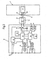
- ein Blockschaltbild von Betätigerelement, Lesekopf und Auswerteeinrichtung,
- Fig. 3
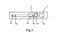
- eine schematisierte Darstellung des Betätigers.
- Fig. 1
- a section through the embodiment,
- Fig. 2
- a block diagram of actuator element, read head and evaluation,
- Fig. 3
- a schematic representation of the actuator.
Ein erfindungsgemäßer Sicherheitsschalter besteht aus einem Schaltglied 1 mit einem Gehäuse 3, welches mit dem feststehenden Teil einer Schutzeinrichtung verbindbar ist. Das Gehäuse 3 wird im Kopfbereich durchdrungen von einem Betätigerkanal 5, welcher an beiden Enden offen ist. In den Betätigerkanal 5 ist ein schlüsselartiger Betätiger 7 einführbar, der an dem beweglichen Teil einer Schutzeinrichtung befestigbar ist, beispielsweise an einer Türe oder Haube. Der Betätiger 7 trägt ein in Kunststoff gekapseltes Betätigerelement 9, welches sich innerhalb des Betätigerkanales 5 befindet, wenn der Betätiger 7 vollständig in den Betätigerkanal 5 eingeführt wird. Das Schaltglied 1 weist am Rande des Betätigerkanales 5 einen Lesekopf 11 auf. Bei vollständig eingeführtem Betätiger 7 sind das Betätigerelement 9 und der Lesekopf 11 einander gegenüberliegend angeordnet und können miteinander wechselwirken.An inventive safety switch consists of a switching element 1 with a housing 3, which is connectable to the fixed part of a protective device. The housing 3 is penetrated in the head area by an
Der Lesekopf 11 ist an eine Auswerteeinrichtung 13 angeschlossen. Die Auswerteeinrichtung 13 weist Anschlüsse 15 auf, an die eine Geräteversorgungsspannung von 24 V angelegt ist. Mit diesen Anschlüssen 15 sind die Eingänge eines Reglers 17 verbunden. Der Ausgang des Reglers 17 gibt eine interne Versorgungsspannung von 5 V ab. An dieser sind der Kollektor eines npn-Transistors 19, dem ein pnp-Transistor 21 nachgeschaltet ist, sowie ein erster und, aus Sicherheitsgründen, ein zweiter Mikroprozessor 23 bzw. 25 angeschlossen. Der erste Mikroprozessor 23 wird über eine Steuerleitung zusätzlich vom Regler 17 überwacht. Ein Ausgang des ersten Mikroprozessors 23 ist über einen Verstärker an die Basen der Transistoren 19 und 21 angeschlossen. Während der Kollektor des pnp-Transistors 21 auf Masse liegt, führt von den beiden miteinander verbundenen Emittern der Transistoren 19 und 21 eine Leitung in den Lesekopf 11 und ist dort an eine Spule 27 angeschlossen. Diese Spule 27 ist innerhalb des Lesekopfes 11 auf der dem Betätigerkanal 5 zugewandten Seite angeordnet und verläuft mit ihrer Längsachse parallel zu diesem. Der Spule 27 ist ein Kondensator 29 nachgeschaltet, der einerseits über zwei Widerstände 31 auf Masse liegt, und andererseits über einen Empfangsverstärker 33 mit Bandpaßfilter an je einem Eingang der beiden Mikroprozessoren 23 und 25 angeschlossen ist. Parallel zu jedem der beiden Widerstände 31 ist aus Sicherheitsgründen jeweils eine Pegelüberwachung 35 angeschlossen, von denen eine an einen Eingang des ersten Mikroprozessors 23 und die andere an einen Eingang des zweiten Mikroprozessors 25 angeschlossen ist.The reading
Der erste Mikroprozessor 23 generiert aus dem Rechnertakt eine Frequenz von 125 kHz, mit der er die beiden Transistoren 19 und 21 ansteuert, welche abwechselnd vom gesperrten in den gesättigten Zustand schalten. Durch diesen Takt wird der aus der Spule 27 und dem Kondensator 29 bestehende Schwingkreis, dessen Resonanzfrequenz ebenfalls 125 kHz beträgt, zu Schwingungen angeregt. Dabei strahlt die Spule 27 ein magnetisches Wechselfeld ab. Die Widerstände 31 begrenzen den Strom im Schwingkreis und damit die Amplitude des magnetischen Wechselfeldes. Zugleich wird auch der Abstand zwischen Betätigerelement 9 und Lesekopf 11 festgelegt, bei dem beide noch zusammenwirken können. Da die Widerstände 31 doppelt vorhanden sind, können die Pegelüberwachungen 35 durch Vergleich eine Drift eines der Widerstände 31 erkennen.The
Im Betätigerelement 9 ist als Induktivität eine Betätigerspule 37 vorgesehen, welche auf der dem Lesekopf 11 zugewandten Seite in Längsrichtung des Betätigers 7 angeordnet ist. Die Betätigerspule 37 bildet zusammen mit einem Betätigerkondensator 39 einen Schwingkreis, zu dem ein IC-Baustein 41 parallel liegt. Wenn bei vollständig eingeführtem Betätiger 7 das Betätigerelement 9 und der Lesekopf 11 einander gegenüberliegen, bilden die Spule 27 und die Betätigerspule 37 einen Transformator, also einen Übertrager. Da zwischen den beiden Spulen 27, 37 ein Spalt vorhanden ist, weist der Transformator einen geringen Kopplungsgrad auf (typischerweise zwischen 0,01 und 0,1). Das von der Spule 27 abgestrahlte magnetische Wechselfeld induziert in der Betätigerspule 37 eine Spannung und erregt somit im Schwingkreis 37, 39 eine Schwingung. Der IC-Baustein 41 weist einen Gleichrichter auf, wodurch er dem Schwingkreis 37, 39 Energie entnehmen kann. Ferner weist der IC-Baustein 41 einen EEPROM auf, der einen 32 Bit langen Code speichert, mit dem das Betätigerelement 9 eindeutig identifizierbar ist. Der IC-Baustein 41 moduliert mit diesem Code die Amplitude im Schwingkreis 37, 39 mit einer Rate von 1 Bit pro msec. Die Betätigerspule 37 koppelt zurück auf die Spule 27 im Lesekopf 11, wodurch dessen Schwingkreis 37, 39 ebenfalls moduliert wird. Über den Empfangsverstärker 33 wird dieses modulierte Signal den Mikroprozessoren 23 und 25 zugeführt.In the
Jeder der beiden Mikroprozessoren 23 und 25 weist einen EEPROM 43 auf, in dem ein 32 Bit langer Code gespeichert ist, mit dem der Lesekopf 11 eindeutig identifizierbar ist. Die beiden Mikroprozessoren 23 und 25 stellen unabhängig voneinander fest, ob vom Betätigerelement 9 überhaupt ein Code übertragen wird, und ob dieser zu demjenigen Code aus dem EEPROM 23 paßt, also ob das einander zugehörige Paar von Betätigerelement 9 und Lesekopf 11 gegenüberliegt. Nur im letztgenannten Fall gibt der Mikroprozessor 23 bzw. 25 über einen Verstärker einem Relais 45 das Signal zum Schließen eines Schalters 47. Zur größeren Sicherheit sind dabei zu den Schließen der Schalter 47 zwangsgeführte Öffnerkontakte und Leitungen vorgesehen, mit denen jeder Mikroprozessor 23 und 25 den Schaltzustand des jeweiligen anderen Relais 45 feststellen kann. Die beiden Schalter 47 bilden die Ausgänge des Sicherheitsschalters und werden beispielsweise in Serie geschaltet dazu verwendet, die Spannungszufuhr der mit der Schutzeinrichtung versehenen Maschine zu steuern. Ist der Abstand zwischen Betätigerelement 9 und Lesekopf 11 zu groß, also beispielsweise bei nicht in den Betätigerkanal 5 eingeführtem Betätiger 7 (d.h. einer geöffneten Schutzeinrichtung), können die Mikroprozessoren 23, 25 keine passenden Codes feststellen, so daß sie das Signal zum Öffnen der Schalter 47 und damit zum Abschalten der Spannungszufuhr der Maschine geben.Each of the two
Zur Erhöhung der Sicherheit weist das Schaltglied 1 einen in Längsrichtung des Gehäuses 3 verschiebbaren Stößel 51, der vorzugsweise als Anker eines Hubmagneten ausgebildet ist. Der Stößel 51 kann den senkrecht zu seiner Bewegungsrichtung verlaufenden Betätigerkanal 5 durchqueren und auf der gegenüberliegenden Seite in eine Ausnehmung des Gehäuses 3 eingreifen. Der Betätiger 7 weist eine Öffnung 53 auf, durch die der Stößel 51 greifen kann, wenn der Betätiger 7 vollständig in den Betätigerkanal 5 eingeführt ist. Der Stößel 51 ist entgegen der Hubrichtung des Magneten federbelastet. Die Anordnung und die Ansteuerung des Hubmagneten ist dabei so gewählt, daß bei vollständig in den Betätigerkanal 5 eingeführtem Betätiger 7 der Stößel 51 unter Durchgreifen der Öffnung 53 in die Ausnehmung im Kopf des Gehäuses 3 eingreift und den Betätiger 7 verriegelt. Der Stößel 51 gibt dabei den Betätiger 7 nach Abschalten der Maschine erst wieder frei, wenn die Maschine zum Stillstand gekommen ist, so daß verhindert wird, daß die Schutzeinrichtung bereits geöffnet werden kann während des Auslaufens der Maschine. Zur Positionsüberwachung des Stößels 51 weist dieser ein weiteres Betätigerelement 55 auf, das wie das Betätigerelement 9 ausgebildet ist. Ferner weist das Schaltglied 1 im Gehäuse 3 einen weiteren Lesekopf 57 auf, der wie der Lesekopf 11 ausgebildet ist. Das weitere Betätigerelement 55 und der weitere Lesekopf 57 sind dabei so angeordnet, daß sie einander gegenüberliegen, wenn der Stößel 51 den Betätiger 7 verriegelt. Die dem weiteren Lesekopf 57 nachgeschaltete weitere Auswerteeinrichtung weist zwei Schalter auf, die vorzugsweise mit den Schaltern 47 der Auswerteeinrichtung 13 in Serie gelegt werden.To increase safety, the switching element 1 has a displaceable in the longitudinal direction of the housing 3
Der Betätiger 7 besteht aus Kunststoff. An dem von der Öffnung 53 abgewandten Ende sind Befestigungslöcher vorgesehen, mit denen der Betätiger 7 am beweglichen Teil der Schutzeinrichtung befestigt wird. Eine aus Kupferdraht bestehende Windung der Betätigerspule 37 ist dabei aus dem Betätigerelement 9 heraus, auf dem Betätiger 7 entlang um die Befestigungslöcher 59 herum und zurück zum Betätigerelement 9 geführt. Die Windung kann auch noch um die Öffnung 53 gelegt sein. Bei einem Bruch des Betätigers 7 wird diese Windung und damit die Betätigerspule 37 aufgebrochen, so daß das Betätigerelement 9 nicht mehr auf das magnetische Wechselfeld des Lesekopfes 11 ansprechen kann. In diesem Fall wird dem Schaltglied 1 eine geöffnete Schutzeinrichtung signalisiert, so daß der Sicherheitsschalter in den sicheren Zustand übergeht, also die Spannungsversorgung der Maschine abschaltet.The
Claims (7)
- Safety switch for monitoring movable protection devices havinga) a switching member (1) which has at least one reading head (11, 57), andb) an actuating element (9, 55) which is movable relative to the reading head (11, 57) and which co-operates in a contactless manner with the reading head (11, 57),
whereinc) the actuating element (9, 55) has an inductor (37) for co-operation with the reading head (11, 57),d) the reading head (11, 57) also has an inductor (27) which co-operates with the inductor (37) of the actuating element (9, 55) via a magnetic alternating field,e) the actuating element (9, 55) draws its energy for operation from the magnetic alternating field, andf) an evaluation device (13) is connected downstream of the reading head (11, 57),g) the actuating element (9, 55) contains an electronic code in a store (41), which code clearly identifies the actuating element (9, 55),h) the evaluation device (13) contains an electronic code in at least one other store (43), which code clearly identifies the reading head (11, 57) or the switching member (1),i) the reading head (11, 57) also receives a signal with the code of the actuating element (9, 55) via the inductor (27) which constructs the magnetic alternating field for operating the actuating element (9, 55),j) those elements (23, 25, 35, 43) of the evaluation device (13) which are provided for the evaluation of the signal received by the reading head (11, 57) are present at least in duplicate,k) and the evaluation device (13) has a comparison device (23, 25) in order to compare the code which is emitted by the actuating element (9, 55) and which is received by the reading head (11, 57) with the code stored in the evaluation device (13). - Safety switch according to claim 1, characterised in that the actuating element (9, 55) emits the code stored therein when the reading head (11, 57) is stimulated.
- Safety switch according to claim 1 or 2, characterised in that an actuator (7) can be introduced into a housing (3) of the switching member (1).
- Safety switch according to claim 3, characterised in that the actuating element (9) is provided on the actuator (7) .
- Safety switch according to claim 3, characterised in that the actuating element (55) is provided on a slide (51) which locks the actuator (7).
- Safety switch according to any one of claims 3 to 5, characterised in that at least one winding of the inductor (37) of the actuating element (9) extends over nearly the entire length of the actuator (7).
- Safety switch according to any one of claims 1 to 6, characterised by the use for a protection device of a machine or an installation.
Applications Claiming Priority (3)
| Application Number | Priority Date | Filing Date | Title |
|---|---|---|---|
| DE19711588 | 1997-03-20 | ||
| DE19711588A DE19711588A1 (en) | 1997-03-20 | 1997-03-20 | Safety switch |
| PCT/EP1997/007302 WO1998043351A1 (en) | 1997-03-20 | 1997-12-24 | Safety switch |
Publications (3)
| Publication Number | Publication Date |
|---|---|
| EP0968567A1 EP0968567A1 (en) | 2000-01-05 |
| EP0968567B1 EP0968567B1 (en) | 2001-07-11 |
| EP0968567B2 true EP0968567B2 (en) | 2008-01-09 |
Family
ID=7823991
Family Applications (1)
| Application Number | Title | Priority Date | Filing Date |
|---|---|---|---|
| EP97953925A Expired - Lifetime EP0968567B2 (en) | 1997-03-20 | 1997-12-24 | Safety switch |
Country Status (6)
| Country | Link |
|---|---|
| US (1) | US6409083B1 (en) |
| EP (1) | EP0968567B2 (en) |
| JP (1) | JP2002501698A (en) |
| AT (1) | ATE203129T1 (en) |
| DE (2) | DE19711588A1 (en) |
| WO (1) | WO1998043351A1 (en) |
Cited By (3)
| Publication number | Priority date | Publication date | Assignee | Title |
|---|---|---|---|---|
| EP1738383B1 (en) | 2004-04-19 | 2010-05-05 | Pilz GmbH & CO. KG | Signaling device for a protective circuit |
| DE102012101933A1 (en) | 2012-03-07 | 2013-09-12 | Pilz Gmbh & Co. Kg | Sensor arrangement for detecting a safe system state of an automated system |
| DE102015113937A1 (en) | 2015-08-21 | 2017-02-23 | Elobau Gmbh & Co. Kg | Wireless surveillance system |
Families Citing this family (47)
| Publication number | Priority date | Publication date | Assignee | Title |
|---|---|---|---|---|
| DE19917212A1 (en) * | 1999-04-16 | 2000-11-02 | Euchner Gmbh & Co | Device for switching a connection depending on the state of a device to be monitored, in particular a safety switch |
| DE19917211C1 (en) | 1999-04-16 | 2000-11-16 | Euchner Gmbh & Co | Device for switching a connection depending on the state of a device to be monitored, in particular a safety switch |
| US6539760B1 (en) | 1999-05-24 | 2003-04-01 | K.A. Schmersal Gmbh & Co. | Monitoring device |
| DE19934370C2 (en) * | 1999-07-22 | 2001-05-17 | Schmersal K A Gmbh & Co | Monitoring device |
| GB2353361A (en) * | 1999-08-18 | 2001-02-21 | Walton Green Andrew John Scott | Proximity switch comprising relatively movable tuned circuits |
| DE19953898C5 (en) * | 1999-11-10 | 2004-07-01 | K.A. Schmersal Gmbh & Co | Access safety device |
| DE10043237C1 (en) * | 2000-09-02 | 2001-11-29 | Schmersal K A Gmbh & Co | Code source detection device has read head with stimulator interacting with code source stimulation element, oscillation element natural frequency stored in evaluation circuit |
| DE10216225A1 (en) | 2002-04-08 | 2003-10-30 | Euchner Gmbh & Co | Electromagnetic locking system of a safety switch |
| DE10222186C1 (en) * | 2002-05-18 | 2003-10-09 | Schmersal K A Gmbh & Co | Safety switch has comparator providing switch signal if energy induced in receiver element during period following electromagnetic signal emission exceeds/falls below predefined threshold |
| DE10228232C1 (en) * | 2002-06-25 | 2003-09-25 | Schmersal K A Gmbh & Co | Safety switch operator uses inductively activated LC resonant circuit providing electromagnetic AC field of given frequency |
| DE10230564A1 (en) * | 2002-07-05 | 2004-01-29 | Gerhard Thiel | Coded locking device for machine safety cover has projecting arms provided with passive components fitting into corresponding seatings provided with matching active components |
| DE10234984B4 (en) * | 2002-07-31 | 2006-07-06 | Siemens Ag | switching device |
| DE10305704B3 (en) * | 2003-02-12 | 2004-06-24 | K.A. Schmersal Gmbh & Co | Security restraint for door or window has pivoted bolt of restraint device engaging sliding operating element of door or window operating device |
| EP1455454A3 (en) * | 2003-03-07 | 2009-09-30 | Pilz Auslandsbeteiligungen GmbH | Inductive monitoring device and method for monitoring the distance between a first and a second coil |
| DE10334653B4 (en) | 2003-07-21 | 2005-06-09 | Pilz Gmbh & Co. Kg | Method and device for safely monitoring a closed position of two relatively movable parts |
| DE10348884A1 (en) * | 2003-10-14 | 2005-05-25 | Pilz Gmbh & Co. Kg | Safety switch, especially emergency shut-off switch, for safe shut-off of hazardous device has transponder, reader unit arranged so reader unit can read transponder in first position of control element but not in second |
| DE10348527B3 (en) * | 2003-10-18 | 2005-08-18 | K.A. Schmersal Gmbh & Co | Magnetic safety lock for a movable safety device |
| NL1025100C1 (en) * | 2003-12-22 | 2005-06-23 | Johannes Leonardus Henr Ceelen | Electronic security device. |
| JP4444972B2 (en) | 2004-01-09 | 2010-03-31 | ピルツ ゲーエムベーハー アンド コー.カーゲー | Safety switch for monitoring the closed position of the two parts |
| DE102004002438A1 (en) * | 2004-01-09 | 2005-09-22 | Pilz Gmbh & Co. Kg | Safety switch for monitoring closing position of relatively movable parts, especially for automated system safety door, has directional sensor antenna magnetic characteristic for transformer coupling with actuator in 2 orthogonal directions |
| DE102004016632B4 (en) * | 2004-03-29 | 2006-03-23 | Pilz Gmbh & Co. Kg | Safety switch for monitoring a protective door on an automated unit has a sensor and an activating device with a component for generating a sensor signal |
| DE502005008743D1 (en) * | 2004-03-29 | 2010-02-04 | Pilz Gmbh & Co Kg | SECURITY SWITCH FOR MONITORING A CLOSURE POSITION TWO RELATIVE TO MOBILE PARTS |
| DE102004049024B3 (en) * | 2004-09-20 | 2006-04-13 | K.A. Schmersal Holding Kg | Position monitoring device |
| EP1677167B1 (en) * | 2005-01-03 | 2013-05-22 | K. A. Schmersal GmbH & Co. KG | Operating modes selector switch |
| DE102005013102A1 (en) * | 2005-03-18 | 2006-09-21 | K.A. Schmersal Holding Kg | Non-contact switch |
| GB0601990D0 (en) * | 2006-02-01 | 2006-03-15 | Eja Ltd | Safety switch |
| DE102006032226B4 (en) | 2006-07-07 | 2009-12-10 | Pilz Gmbh & Co. Kg | Method and device for safe distance monitoring |
| EP1901429B1 (en) * | 2006-09-13 | 2011-04-20 | Siemens Aktiengesellschaft | Method and apparatus for accelerated detection of an event triggering a contactless switching system |
| DE102006046437B4 (en) * | 2006-09-25 | 2009-04-09 | Euchner Gmbh + Co. Kg | Device for monitoring the state of a safety-related device |
| DE202006015768U1 (en) | 2006-10-14 | 2006-12-14 | Sick Ag | Monitoring system for closing doors comprises transponder mounted on door and detector coil mounted on door frame, functioning of coil being checked using second coil which reduces strength of its magnetic field |
| ATE504976T1 (en) | 2006-12-01 | 2011-04-15 | Siemens Ag | SENSOR UNIT WITH SAFETY SYSTEM |
| CN101772613B (en) | 2007-08-07 | 2013-08-21 | 泰利斯泰普斯公司 | A ladder accessory |
| GB0801706D0 (en) | 2008-01-31 | 2008-03-05 | Eja Ltd | Safety switch |
| DE112010000460B4 (en) * | 2009-04-28 | 2015-12-03 | Omron Corp. | PROXIMITY SWITCH |
| DE102009059050B4 (en) | 2009-12-15 | 2017-10-12 | Euchner Gmbh + Co. Kg | Locking system for a safety switch and safety switch with such a locking system |
| DE102010034472B4 (en) | 2010-08-05 | 2017-10-12 | Euchner Gmbh + Co. Kg | Locking device for a device for monitoring the state of a protective device of a machine |
| DE102010035765B4 (en) | 2010-08-20 | 2012-03-22 | Euchner Gmbh + Co. Kg | Device for monitoring the state of a protective device of a machine, in particular safety switch, and method for operating such a device |
| DE102011119413A1 (en) * | 2011-11-21 | 2013-05-23 | Euchner Gmbh + Co. Kg | Device for controlling the operation of a machine, locking insert for such a device and associated operating method |
| ITVI20110342A1 (en) | 2011-12-29 | 2013-06-30 | Pizzato Elettrica Srl | ELECTRONIC SAFETY DEVICE FOR A PROTECTION BARRIER |
| DE102012109311B4 (en) | 2012-10-01 | 2022-01-05 | Pilz Gmbh & Co. Kg | Device for safely monitoring a closed position of two parts that can move relative to one another |
| DE102012021968B4 (en) | 2012-10-31 | 2015-10-22 | Euchner Gmbh + Co. Kg | Device for releasably locking a predeterminable state of a device and safety switch with such a device |
| DE102013014456B4 (en) * | 2013-08-30 | 2016-03-24 | Euchner Gmbh + Co. Kg | Actuator of a safety switch and safety switch with such an actuator |
| IT201600117298A1 (en) * | 2016-11-21 | 2018-05-21 | Pizzato Elettrica Srl | SECURITY SWITCH WITH DIFFERENTIATED CPU |
| CH714313A1 (en) * | 2017-11-09 | 2019-05-15 | Elesta Gmbh Ostfildern De Zweigniederlassung Bad Ragaz | Device with a sensor and an actuator, in particular for use as a door contact switch, and method for testing the device. |
| JP7010755B2 (en) | 2018-04-13 | 2022-01-26 | 株式会社キーエンス | Safety door switch |
| JP7122851B2 (en) | 2018-04-13 | 2022-08-22 | 株式会社キーエンス | safety switch |
| JP2021173062A (en) * | 2020-04-24 | 2021-11-01 | パナソニックIpマネジメント株式会社 | Safety switch and memory control method |
Citations (4)
| Publication number | Priority date | Publication date | Assignee | Title |
|---|---|---|---|---|
| DE3616389A1 (en) † | 1986-05-15 | 1987-11-19 | Turck Werner Kg | Non-contact proximity switch |
| DE4303367C1 (en) † | 1993-02-05 | 1994-02-24 | Schmersal K A Gmbh & Co | Security switch for safety door - has switch operating element fitted in switch housing to rotate cam discs acting as operating roller for movable contact carrier |
| DE19501004A1 (en) † | 1994-05-03 | 1995-11-09 | Telefunken Microelectron | Method for operating a data transmission system from a transponder and a reading device |
| DE4412653A1 (en) † | 1994-04-13 | 1996-08-01 | Schmersal K A Gmbh & Co | Monitoring device |
Family Cites Families (13)
| Publication number | Priority date | Publication date | Assignee | Title |
|---|---|---|---|---|
| JPS61196080A (en) * | 1985-02-21 | 1986-08-30 | 日産自動車株式会社 | Wireless user discrimination apparatus |
| DE3600979A1 (en) * | 1986-01-15 | 1987-07-16 | Rheinmetall Gmbh | CONTACTLESS SIGNALER |
| JP2546842B2 (en) * | 1987-06-16 | 1996-10-23 | 日産自動車株式会社 | Vehicle locking / unlocking control device |
| DE3837218A1 (en) | 1988-11-02 | 1990-05-03 | Elektronik Geraetewerk Gmbh | Creep and rotational movement monitoring in the case of a protection device having normal or enhanced safety, of Type EBUD-00 (...99) |
| CH680082A5 (en) * | 1989-12-15 | 1992-06-15 | Bauer Kaba Ag | |
| JPH03228988A (en) * | 1990-02-02 | 1991-10-09 | Daishowa Seiki Co Ltd | Discriminating device for closing and opening door |
| GB9017910D0 (en) * | 1990-08-15 | 1990-09-26 | Vaseal Electronics Limited | Improvements in and relating to proximity switches |
| DE4041550C3 (en) | 1990-12-22 | 2003-08-28 | Schmersal K A Gmbh & Co | Safety device with at least one non-contact sensor |
| DE4438039A1 (en) | 1994-10-25 | 1996-05-02 | Leon Helma Christina | Self-testing personnel safety monitoring system with switch=off detection point |
| JP3670719B2 (en) * | 1995-07-24 | 2005-07-13 | 株式会社ユーシン | Keyless entry system |
| US6243004B1 (en) * | 1996-08-22 | 2001-06-05 | Kenneth E. Flick | Vehicle security system with inductive coupling to a vehicle having a data communications bus and related methods |
| JPH10159419A (en) * | 1996-11-29 | 1998-06-16 | Aisin Seiki Co Ltd | Auto-door-lock control device |
| JP3256666B2 (en) * | 1996-12-25 | 2002-02-12 | 三菱電機株式会社 | Vehicle remote control device and vehicle security device |
-
1997
- 1997-03-20 DE DE19711588A patent/DE19711588A1/en not_active Withdrawn
- 1997-12-24 US US09/319,042 patent/US6409083B1/en not_active Expired - Lifetime
- 1997-12-24 DE DE59704043T patent/DE59704043D1/en not_active Expired - Lifetime
- 1997-12-24 AT AT97953925T patent/ATE203129T1/en not_active IP Right Cessation
- 1997-12-24 EP EP97953925A patent/EP0968567B2/en not_active Expired - Lifetime
- 1997-12-24 JP JP54477698A patent/JP2002501698A/en active Pending
- 1997-12-24 WO PCT/EP1997/007302 patent/WO1998043351A1/en active IP Right Grant
Patent Citations (5)
| Publication number | Priority date | Publication date | Assignee | Title |
|---|---|---|---|---|
| DE3616389A1 (en) † | 1986-05-15 | 1987-11-19 | Turck Werner Kg | Non-contact proximity switch |
| DE4303367C1 (en) † | 1993-02-05 | 1994-02-24 | Schmersal K A Gmbh & Co | Security switch for safety door - has switch operating element fitted in switch housing to rotate cam discs acting as operating roller for movable contact carrier |
| DE4412653A1 (en) † | 1994-04-13 | 1996-08-01 | Schmersal K A Gmbh & Co | Monitoring device |
| EP0677830B1 (en) † | 1994-04-13 | 1998-07-08 | K.A. SCHMERSAL GmbH & Co. | Monitoring apparatus |
| DE19501004A1 (en) † | 1994-05-03 | 1995-11-09 | Telefunken Microelectron | Method for operating a data transmission system from a transponder and a reading device |
Non-Patent Citations (2)
| Title |
|---|
| hitag, System Overview, Prospekt der Mikron G.m.b.H., Philips Electronics N.V. 1996, Date of release: 10/96 † |
| Merkblatt für die Auswahl und Anbringung von Näherungsschaltern in Verriegelungseinrichtungen für Sicherheitsfunktionen, Berufsgenossenschaft der Feinmechanik und Elektrotechnik, Fassung 7/96 † |
Cited By (3)
| Publication number | Priority date | Publication date | Assignee | Title |
|---|---|---|---|---|
| EP1738383B1 (en) | 2004-04-19 | 2010-05-05 | Pilz GmbH & CO. KG | Signaling device for a protective circuit |
| DE102012101933A1 (en) | 2012-03-07 | 2013-09-12 | Pilz Gmbh & Co. Kg | Sensor arrangement for detecting a safe system state of an automated system |
| DE102015113937A1 (en) | 2015-08-21 | 2017-02-23 | Elobau Gmbh & Co. Kg | Wireless surveillance system |
Also Published As
| Publication number | Publication date |
|---|---|
| DE59704043D1 (en) | 2001-08-16 |
| DE19711588A1 (en) | 1998-09-24 |
| ATE203129T1 (en) | 2001-07-15 |
| EP0968567A1 (en) | 2000-01-05 |
| US6409083B1 (en) | 2002-06-25 |
| JP2002501698A (en) | 2002-01-15 |
| EP0968567B1 (en) | 2001-07-11 |
| WO1998043351A1 (en) | 1998-10-01 |
Similar Documents
| Publication | Publication Date | Title |
|---|---|---|
| EP0968567B2 (en) | Safety switch | |
| EP0986176B1 (en) | Contactless security switch | |
| EP2041871B1 (en) | Method and device for secure separation monitoring | |
| DE19953898C2 (en) | Access safety device | |
| DE10334653A1 (en) | Method and device for safely monitoring a closed position of two relatively movable parts | |
| DE4240628C2 (en) | Monitoring device on a textile machine | |
| DE102005009489A1 (en) | Set of electronic components for a position-detection device has a wake-up device for processing a wakening current pulse in a Wiegand coil | |
| DE102006046437B4 (en) | Device for monitoring the state of a safety-related device | |
| EP3517822B1 (en) | Interlock with enable signal | |
| DE112010000460B4 (en) | PROXIMITY SWITCH | |
| CH658735A5 (en) | Device for identifying an information. | |
| EP3502539A1 (en) | Safety device and method for operating a safety device | |
| WO2005067145A1 (en) | Safety switch for monitoring a closing position of two parts which can be displaced in relation to each other | |
| DE10252025A1 (en) | Lock has interrogation head fixed to housing so as to only receive identification signals from transponders fixed to locking bar and holder if locking bar is in closed position and locked by holder | |
| EP1473511B1 (en) | Device for protection of access | |
| EP3367569A1 (en) | Safety switch | |
| DE102004016632B4 (en) | Safety switch for monitoring a protective door on an automated unit has a sensor and an activating device with a component for generating a sensor signal | |
| EP0814490A2 (en) | Safety device for position switch | |
| EP0900363B1 (en) | Method of controlling a digital sensor, and corresponding digital sensor | |
| EP1730759B1 (en) | Safety switch for monitoring a closed position of two parts that are movable relative to one another | |
| DE2915110C2 (en) | Inductive two-wire proximity switch | |
| DE19855207C1 (en) | Contactless switch for activating identification system in access control system, has coil in which voltage is induced by changing magnetic flux when code medium approaches/leaves switch to activate transmitter | |
| EP0363618B1 (en) | Turnstile | |
| DE4341333A1 (en) | Motor vehicle anti-theft device | |
| DE1524642B1 (en) | Arrangement for registering the operating data of one or more production machines |
Legal Events
| Date | Code | Title | Description |
|---|---|---|---|
| PUAI | Public reference made under article 153(3) epc to a published international application that has entered the european phase |
Free format text: ORIGINAL CODE: 0009012 |
|
| 17P | Request for examination filed |
Effective date: 19990121 |
|
| AK | Designated contracting states |
Kind code of ref document: A1 Designated state(s): AT BE CH DE FR GB IT LI NL SE |
|
| GRAG | Despatch of communication of intention to grant |
Free format text: ORIGINAL CODE: EPIDOS AGRA |
|
| GRAG | Despatch of communication of intention to grant |
Free format text: ORIGINAL CODE: EPIDOS AGRA |
|
| GRAH | Despatch of communication of intention to grant a patent |
Free format text: ORIGINAL CODE: EPIDOS IGRA |
|
| 17Q | First examination report despatched |
Effective date: 20001129 |
|
| GRAH | Despatch of communication of intention to grant a patent |
Free format text: ORIGINAL CODE: EPIDOS IGRA |
|
| GRAA | (expected) grant |
Free format text: ORIGINAL CODE: 0009210 |
|
| AK | Designated contracting states |
Kind code of ref document: B1 Designated state(s): AT BE CH DE FR GB IT LI NL SE |
|
| REF | Corresponds to: |
Ref document number: 203129 Country of ref document: AT Date of ref document: 20010715 Kind code of ref document: T |
|
| REG | Reference to a national code |
Ref country code: CH Ref legal event code: NV Representative=s name: ISLER & PEDRAZZINI AG Ref country code: CH Ref legal event code: EP |
|
| REF | Corresponds to: |
Ref document number: 59704043 Country of ref document: DE Date of ref document: 20010816 |
|
| ITF | It: translation for a ep patent filed |
Owner name: BUZZI, NOTARO&ANTONIELLI D'OULX |
|
| ET | Fr: translation filed | ||
| GBT | Gb: translation of ep patent filed (gb section 77(6)(a)/1977) |
Effective date: 20011011 |
|
| REG | Reference to a national code |
Ref country code: GB Ref legal event code: IF02 |
|
| PLBQ | Unpublished change to opponent data |
Free format text: ORIGINAL CODE: EPIDOS OPPO |
|
| PLBI | Opposition filed |
Free format text: ORIGINAL CODE: 0009260 |
|
| PLBF | Reply of patent proprietor to notice(s) of opposition |
Free format text: ORIGINAL CODE: EPIDOS OBSO |
|
| 26 | Opposition filed |
Opponent name: K.A. SCHMERSAL GMBH & CO. Effective date: 20020409 |
|
| NLR1 | Nl: opposition has been filed with the epo |
Opponent name: K.A. SCHMERSAL GMBH & CO. |
|
| PLBF | Reply of patent proprietor to notice(s) of opposition |
Free format text: ORIGINAL CODE: EPIDOS OBSO |
|
| PLBF | Reply of patent proprietor to notice(s) of opposition |
Free format text: ORIGINAL CODE: EPIDOS OBSO |
|
| TPAD | Observations filed by third parties |
Free format text: ORIGINAL CODE: EPIDOS TIPA |
|
| APBP | Date of receipt of notice of appeal recorded |
Free format text: ORIGINAL CODE: EPIDOSNNOA2O |
|
| APAH | Appeal reference modified |
Free format text: ORIGINAL CODE: EPIDOSCREFNO |
|
| APAH | Appeal reference modified |
Free format text: ORIGINAL CODE: EPIDOSCREFNO |
|
| APAL | Date of receipt of statement of grounds of an appeal modified |
Free format text: ORIGINAL CODE: EPIDOSCNOA3O |
|
| APBQ | Date of receipt of statement of grounds of appeal recorded |
Free format text: ORIGINAL CODE: EPIDOSNNOA3O |
|
| APBU | Appeal procedure closed |
Free format text: ORIGINAL CODE: EPIDOSNNOA9O |
|
| REG | Reference to a national code |
Ref country code: CH Ref legal event code: PCAR Free format text: ISLER & PEDRAZZINI AG;POSTFACH 1772;8027 ZUERICH (CH) |
|
| PUAH | Patent maintained in amended form |
Free format text: ORIGINAL CODE: 0009272 |
|
| STAA | Information on the status of an ep patent application or granted ep patent |
Free format text: STATUS: PATENT MAINTAINED AS AMENDED |
|
| 27A | Patent maintained in amended form |
Effective date: 20080109 |
|
| AK | Designated contracting states |
Kind code of ref document: B2 Designated state(s): AT BE CH DE FR GB IT LI NL SE |
|
| REG | Reference to a national code |
Ref country code: CH Ref legal event code: AEN Free format text: AUFRECHTERHALTUNG DES PATENTES IN GEAENDERTER FORM |
|
| NLR2 | Nl: decision of opposition |
Effective date: 20080109 |
|
| REG | Reference to a national code |
Ref country code: SE Ref legal event code: RPEO |
|
| GBTA | Gb: translation of amended ep patent filed (gb section 77(6)(b)/1977) |
Effective date: 20080416 |
|
| NLR3 | Nl: receipt of modified translations in the netherlands language after an opposition procedure | ||
| ET3 | Fr: translation filed ** decision concerning opposition | ||
| PLAB | Opposition data, opponent's data or that of the opponent's representative modified |
Free format text: ORIGINAL CODE: 0009299OPPO |
|
| PGFP | Annual fee paid to national office [announced via postgrant information from national office to epo] |
Ref country code: NL Payment date: 20081231 Year of fee payment: 12 Ref country code: CH Payment date: 20081229 Year of fee payment: 12 |
|
| PGFP | Annual fee paid to national office [announced via postgrant information from national office to epo] |
Ref country code: AT Payment date: 20081106 Year of fee payment: 12 |
|
| PGFP | Annual fee paid to national office [announced via postgrant information from national office to epo] |
Ref country code: BE Payment date: 20081128 Year of fee payment: 12 |
|
| BERE | Be: lapsed |
Owner name: *EUCHNER G.M.B.H. + CO. Effective date: 20091231 |
|
| REG | Reference to a national code |
Ref country code: NL Ref legal event code: V1 Effective date: 20100701 |
|
| REG | Reference to a national code |
Ref country code: CH Ref legal event code: PL |
|
| PG25 | Lapsed in a contracting state [announced via postgrant information from national office to epo] |
Ref country code: AT Free format text: LAPSE BECAUSE OF NON-PAYMENT OF DUE FEES Effective date: 20091224 |
|
| PG25 | Lapsed in a contracting state [announced via postgrant information from national office to epo] |
Ref country code: NL Free format text: LAPSE BECAUSE OF NON-PAYMENT OF DUE FEES Effective date: 20100701 Ref country code: LI Free format text: LAPSE BECAUSE OF NON-PAYMENT OF DUE FEES Effective date: 20091231 Ref country code: CH Free format text: LAPSE BECAUSE OF NON-PAYMENT OF DUE FEES Effective date: 20091231 Ref country code: BE Free format text: LAPSE BECAUSE OF NON-PAYMENT OF DUE FEES Effective date: 20091231 |
|
| REG | Reference to a national code |
Ref country code: DE Ref legal event code: R082 Ref document number: 59704043 Country of ref document: DE Representative=s name: RUCKH, RAINER, DIPL.-PHYS. DR.RER.NAT., DE |
|
| REG | Reference to a national code |
Ref country code: FR Ref legal event code: PLFP Year of fee payment: 19 |
|
| PGFP | Annual fee paid to national office [announced via postgrant information from national office to epo] |
Ref country code: GB Payment date: 20151221 Year of fee payment: 19 |
|
| PGFP | Annual fee paid to national office [announced via postgrant information from national office to epo] |
Ref country code: SE Payment date: 20151221 Year of fee payment: 19 Ref country code: FR Payment date: 20151221 Year of fee payment: 19 |
|
| PGFP | Annual fee paid to national office [announced via postgrant information from national office to epo] |
Ref country code: IT Payment date: 20151228 Year of fee payment: 19 Ref country code: DE Payment date: 20160109 Year of fee payment: 19 |
|
| REG | Reference to a national code |
Ref country code: DE Ref legal event code: R119 Ref document number: 59704043 Country of ref document: DE |
|
| REG | Reference to a national code |
Ref country code: SE Ref legal event code: EUG |
|
| GBPC | Gb: european patent ceased through non-payment of renewal fee |
Effective date: 20161224 |
|
| PG25 | Lapsed in a contracting state [announced via postgrant information from national office to epo] |
Ref country code: SE Free format text: LAPSE BECAUSE OF NON-PAYMENT OF DUE FEES Effective date: 20161225 |
|
| REG | Reference to a national code |
Ref country code: FR Ref legal event code: ST Effective date: 20170831 |
|
| PG25 | Lapsed in a contracting state [announced via postgrant information from national office to epo] |
Ref country code: IT Free format text: LAPSE BECAUSE OF NON-PAYMENT OF DUE FEES Effective date: 20161224 Ref country code: FR Free format text: LAPSE BECAUSE OF NON-PAYMENT OF DUE FEES Effective date: 20170102 |
|
| PG25 | Lapsed in a contracting state [announced via postgrant information from national office to epo] |
Ref country code: DE Free format text: LAPSE BECAUSE OF NON-PAYMENT OF DUE FEES Effective date: 20170701 Ref country code: GB Free format text: LAPSE BECAUSE OF NON-PAYMENT OF DUE FEES Effective date: 20161224 |