EP0955907B1 - Ligating clip advance - Google Patents
Ligating clip advance Download PDFInfo
- Publication number
- EP0955907B1 EP0955907B1 EP95928817A EP95928817A EP0955907B1 EP 0955907 B1 EP0955907 B1 EP 0955907B1 EP 95928817 A EP95928817 A EP 95928817A EP 95928817 A EP95928817 A EP 95928817A EP 0955907 B1 EP0955907 B1 EP 0955907B1
- Authority
- EP
- European Patent Office
- Prior art keywords
- pusher
- clips
- housing
- clip
- cam
- Prior art date
- Legal status (The legal status is an assumption and is not a legal conclusion. Google has not performed a legal analysis and makes no representation as to the accuracy of the status listed.)
- Expired - Lifetime
Links
Images


Classifications
-
- A—HUMAN NECESSITIES
- A61—MEDICAL OR VETERINARY SCIENCE; HYGIENE
- A61B—DIAGNOSIS; SURGERY; IDENTIFICATION
- A61B17/00—Surgical instruments, devices or methods, e.g. tourniquets
- A61B17/12—Surgical instruments, devices or methods, e.g. tourniquets for ligaturing or otherwise compressing tubular parts of the body, e.g. blood vessels, umbilical cord
- A61B17/128—Surgical instruments, devices or methods, e.g. tourniquets for ligaturing or otherwise compressing tubular parts of the body, e.g. blood vessels, umbilical cord for applying or removing clamps or clips
- A61B17/1285—Surgical instruments, devices or methods, e.g. tourniquets for ligaturing or otherwise compressing tubular parts of the body, e.g. blood vessels, umbilical cord for applying or removing clamps or clips for minimally invasive surgery
Definitions
- the present invention relates generally to an apparatus for sequentially advancing a plurality of clips that are used to occlude blood vessels, body tissues or organs in surgical procedures, such as laparoscopic surgical procedures, and more particularly, to an apparatus that individually engages and supports each clip during advancement.
- Surgical procedures frequently require the ligation of blood vessels, severed tissues or other organs.
- surgical clip appliers that advance and clamp a clip to the selected vessel, tissue or organ. See, e.g., U.S. Patent Nos. 5,084,057, 4,616,650 and 3,086,208. Because the surgeon will typically apply many clips during the course of an operation, it has been preferred that these clip appliers contain a plurality of automatically advancing clips. Accordingly, an advancing mechanism that feeds the clips one at a time into the clamping mechanism has been necessary.
- the clips are arranged sequentially along a longitudinal axis of the clip applier.
- a spring is located behind the proximal-most clip and is biased to urge all the clips distally.
- Using the spring to advance the clips is unreliable because the spring force can cause the clips to move forward with excessive force, resulting in the clips frictionally jamming against each other or getting wedged within the clip applier.
- the frictional load on the clips is greater than the applied spring force, there will be no advancement. Also, it is possible that more than one clip at a time may advance into the clamping mechanism.
- U.S. Patent Nos. 4,452,376 and 3,899,914 disclose clip appliers wherein the clips are mechanically advanced by the operator who actuates a push bar that engages the proximal-most clip, pushing all the clips forward. While the push bar gives the operator more direct control over advancement of the clips, there still exists the problems of clip jamming and improper feeding because the clips are not visible to the operator, making it difficult to determine whether excessive force is being applied during advancement.
- U.S. Patent No. 4,452,376 also describes a pawl configured to conform to the bail portion of the proximal-most clip that prevents the clips from moving proximally after advancement. The pawl, however, relies only on frictional forces to prevent rearward motion of the clips, which in some instances may be inadequate to hold the clips in place.
- the plurality of clips are advanced by a feed ratchet and a backstop ratchet. Teeth are stamped out of the ratchet bodies to contact each clip individually. Feeding occurs through reciprocating movement of the feed ratchet relative to the backstop ratchet. During clip advancement, the feed ratchet teeth push the clips forward and the backstop ratchet teeth flex out of the way as the clips pass by. When the feed ratchet is pulled back and reset, the backstop ratchet teeth prevent the clips from moving backward and the feed ratchet teeth flex out of the way as they pass over the clips.
- U.S. Patent Nos. 4,624,254, 4,500,024, 4,452,357 and 4,430,997 See U.S. Patent Nos. 4,624,254, 4,500,024, 4,452,357 and 4,430,997.
- the ratchet type of clip advance reduces the problem of clip jamming because each clip is individually engaged by the teeth of the feed and backstop ratchets.
- the mechanism does have its disadvantages. For example, the teeth themselves may become jammed during flexing, which could result in improper advancement or a failure to advance the clips. Additionally, if the teeth do not retain sufficient resiliency, they may fail to properly engage the clips during advancement or may fail to prevent their proximal movement after advancement.
- the clips are attached to a moveable belt structure having retainers that engage each individual clip, U.S. Patent No. 5,192,288.
- the belt structure and its actuation adds an additional element of complexity to the overall design.
- U.S. 4,470,532 corresponding to the preambles of claims 1 and 12 describes a medical stapling device which can insert a series of metal staples adapted to enter living tissue. It has a driver including a plurality of spaced lugs adapted to engage staples spaced at predetermined distances along a track, and a stapler includes means adapted for engagement between the driver and the frame, including cam members on the driver and on the frame that directly interact with each other, for affording positioning of the lugs in engagement with staples spaced along the track when the driver is in its first position, for causing the driver to move the staples along the track and engage the leading staple with the an anvil to close the leading staple during movement of the driver from its first to its second position, and for causing movement of the lugs out of engagement with the staples along the track, around, and into engagement with subsequent staples along the track during movement of the driver from its second position back to its first position.
- a driver including a plurality of spaced lugs adapted to engage
- the present invention is embodied in a clip advance for a multi-fire clip applicator as claimed in claims 1 and 12.
- the clip advance positively advances each clip in the clip stack, thereby reducing the possibility of misfiring or jamming by wedging or friction.
- the clip advance also has a simple and effective construction and is easy to use.
- the clip advance includes a longitudinally extending housing having a first channel for receiving a stack of surgical clips.
- a pusher is mounted in the housing for reciprocating longitudinal movement adjacent the plurality of clips.
- the pusher includes a plurality of tabs arranged to correspondingly engage and distally move respective ones of the plurality of clips when the pusher is moved distally.
- the tabs need not be flexible or resilient as in prior art devices. Accordingly, an advantage of the present invention is that the tabs are not likely to become jammed or wedged during clip advancement.
- a feature of the clip advance is that the pusher and housing are provided with a mechanism that, upon proximal movement of the pusher, lifts the tabs out of longitudinal contacting alignment with the clips. This permits the pusher to be pulled back and reset to engage the next clips in sequence.
- the mechanism for disengaging the tabs from the clips includes a cantilever ramp fixed to the housing and a transversely extending knob on the pusher that is in longitudinally contacting alignment with the cantilever ramp.
- the knob engages and deflects the cantilever ramp out of the way as the knob passes by.
- the knob rides up the cantilever ramp, lifting the tabs out of alignment with the clips until the tabs are pulled back to a location where they can engage the next clips in sequence.
- biasing member that returns the tabs into contacting longitudinal alignment with the clips upon proximal disengagement of the knob from the cantilever ramp.
- the biasing member is a leaf spring fixed to the reciprocating pusher that engages an upper wall of the housing such that the upper wall applies a biasing force to the pusher urging the tabs back into contacting longitudinal alignment with the clips.
- An additional feature of a preferred embodiment of the present invention is a backstop located adjacent the proximal-most clip in the stack of clips.
- the backstop includes a deflectable wing that engages a ratcheting surface of the housing. Distal movement of the backstop relative to the ratcheting surface alternately flexes the wing inward as the wing moves along the ratchet surface, then releases the wing after movement of approximately one clip length. The wing then interfaces with a back wall of the ratcheting surface to prevent proximal movement, thus supporting the clips in their new position.
- the staging bar has a head at its distal end for engaging a distal-most clip in the first channel of the housing and advancing the clip into the clamping mechanism.
- the head of the staging bar also has a proximal ramp surface configured to ride over the distal-most clip upon proximal movement of the staging bar.
- the staging bar has a bend located proximally of the head that engages the housing in such a manner as to bias the head toward the clip.
- a further feature of a preferred embodiment of the invention is a distally extending cantilever arm at the distal end of the housing.
- the cantilever arm has a hook at its distal end in contacting longitudinal alignment with the clips to hold the clip stack back from gravity.
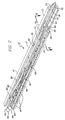
- FIGS. 1 and 2 A clip advance 10 according to the present invention is shown in FIGS. 1 and 2.
- the clip advance 10 includes a housing 12, a plurality of clips 14, a reciprocating pusher 16, a staging bar 18 and a backstop 20.
- the housing 12 is a clam shell type have two symmetrical halves, only one-half of which is shown.
- the housing is preferably molded and made of polycarbonate or other suitable material.
- the housing extends longitudinally and defines two longitudinally extending channels, a lower channel 22 and an upper channel 24.
- the lower and upper channels are separated by a common wall 26.
- the lower channel is configured to receive the plurality of clips 14.
- the upper channel is configured to receive the reciprocating pusher 16 and the staging bar 18.
- the housing has a proximal end 28 and a distal end 30.
- a detent 32 is formed at the distal end 30 of the housing to hold the clip stack back from gravity.
- the detent includes a distally extending cantilever arm 34 with an inwardly extending hook 36 at the free end of the cantilever arm 34.
- the hook 36 is configured to engage the distal-most clip prior to its advancement into a clamping mechanism (not shown).
- the cantilever arm is resilient to flex out of the way when a sufficient distally directed force is applied to the distal-most clip, then, after the clip passes by, the arm returns to its unflexed position to stop the remaining clips in the stack from advancing forward.
- the upper channel 24 of the housing is interrupted by one or more cantilever ramps 38, which may be formed into the housing at the time of molding.
- the cantilever ramps 38 have a proximal portion 40 fixed to a sidewall 42 of the upper channel 24 and a distal ramp portion 44 defining a ramp or cam surface 43.
- the proximal portion 40 extends longitudinally and is spaced from the common wall 26 to form a passage 45.
- the proximal portion is also spaced from an upper wall 47 of the upper channel 24 to form a passage 49.
- the distal ramp portion 44 extends toward the lower channel 22 from the proximal portion 40.
- a cutout 46 is provided in the common wall 26 to permit the ramp portion 44 to extend into the lower channel.
- the cantilever ramps 38 are sufficiently resilient to flex transversely, as will be described in more detail below.
- the clips 14 are preferably each U-shaped having a closed end 48 and two legs 50.
- the clips are arranged in sequential alignment in the lower channel 22 with their legs 50 pointing distally.
- the reciprocating pusher 16 is a longitudinally extending member located in the upper channel 24 of the housing 12.
- the reciprocating pusher includes a longitudinally extending central portion 52 and two outer support portions 54.
- the central portion is lower than the support portions to define a recess 56 for locating the staging bar 18.
- Tabs 58 are punched out longitudinally along the central portion of the reciprocating pusher 16 (see also FIG. 5A). The tabs extend into the lower channel 22 and are spaced so that each tab engages a corresponding clip 14. The length of the tabs are sufficient to engage the closed ends of the clips. The tabs are also sufficiently rigid to apply a distally directed force to the clips in order to advance them forward.
- the support portions 54 of the reciprocating pusher are not continuous for the full length of the pusher. They do, however, have sufficient length to support the pusher on the common wall 26 between the upper and lower channels.
- the support portions may be broken into three sections, such as distal sections 60, mid sections 62 and proximal sections 64. Between the distal and mid sections 60, 62 is a first pair of transversely extending cams or knobs 66. Similarly, between the mid and proximal sections 62, 64 is a second pair of transversely extending cams or knobs 68.
- the knobs 66, 68 are located adjacent the cantilever ramps 38.
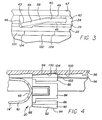
- the knobs are sized to pass through the passages 45 between the cantilever ramps 38 and the common wall 26 and to pass through the passages 49 between the cantilever ramp and the upper wall 47 (see also FIG. 3). The interaction between the knobs and the cantilever ramps will be described in more detail below.
- first set of leaf springs 70 and a second set of leaf springs 72 are stamped out of the reciprocating pusher 16.
- the leaf springs are stamped such that there distal ends 74 remain fixed to the reciprocating pusher. After stamping, the leaf springs are bent upwardly such that they apply a biasing force against the upper wall 47 of the housing, urging the reciprocating pusher down into engagement with the common wall 26.
- the leaf springs 70, 72 are located in the assembled clip advance such that they do not contact the cantilevered ramps 38 during the back and forth movement of the reciprocating pusher.
- Staging bar 18 is another longitudinally extending member that is preferably seated in the recess 56 of the reciprocating pusher.
- the staging bar includes a distal end defining a head 76 having a distal pushing surface 78 and a proximal ramp surface 80.
- the pushing surface 78 extends downwardly into the lower channel 22 to engage the distal-most clip and advance it into the clamping mechanism (not shown).
- the proximal ramp surface causes the head to rise up and over the next clip in sequence to be advanced.
- the staging bar also includes a bend 82 located proximally of the head 76.
- the bend 82 in the staging bar engages the upper wall 47 of the housing and applies a biasing force that urges the head 76 of the staging bar into the lower channel 22 to ensure engagement between the head of the staging bar and the clip to be advanced into the clamping mechanism.
- the backstop 20 is located in the lower channel 22 of the housing.
- the backstop includes a U-shaped midsection 84 and two lateral wings 86.
- distal ends 88 of the lateral wings 86 are fixed to the U-shaped midsection 84.
- Proximal ends 90 of the lateral wings are unattached so that they are permitted to flex toward the U-shaped midsection.
- Each lateral wing 86 includes a generally longitudinally extending lock portion 92 having a beveled surface 94. When the clip advance is assembled, the lock portions 92 are located in longitudinally extending grooves 96 located in a sidewall 98 of the lower channel 22 (see also FIG. 1).
- the sidewall 98 includes ratcheting surfaces 100.
- the backstop 20 is located in the lower channel 22 such that the beveled surfaces 94 of the lateral wings operatively engage the ratcheting surfaces 100. It will be appreciated that as the backstop is moved distally, the lateral wings 86 will be deflected inwardly by the ratcheting surfaces 100 toward the U-shaped midsection 84. Then, the wings will resiliently deflect back to their original position as the backstop reaches its next position in sequence. A rear surface 102 of the wings 86 engages a back wall 104 of the ratcheting surface 100 to prevent backward movement of the backstop after each advancement.
- the clip advance is assembled by placing the clips 14 in sequential alignment in the lower channel 22 of the housing 12.
- the backstop 20 is located proximally adjacent to a proximal-most clip 14'.
- the staging bar 18 is located in the recess 56 of the reciprocating pusher 16 and the combined unit is placed in the upper channel 24 of the housing with the tabs 58 of the reciprocating pusher in longitudinally contacting alignment with their respective clips 14.
- One tab 58 n-1 of the reciprocating pusher is also placed proximally of the U-shaped midsection 84 of the backstop for moving the backstop distally with the clips (see FIGS. 5A-5F).
- the assembled clip advance may be used with a conventional handle having an actuating member (not shown) that engages the proximal ends of the reciprocating pusher 16 and/or the staging bar 18 for proximal and distal movement.
- the actuating member is fixed to the staging bar.
- a pin (not shown) may be used to connect the staging bar to the reciprocating pusher. Since the staging bar may have a greater distance to travel in order to load a clip into the clamping mechanism, the pin may be located in a slot (not shown) in the reciprocating pusher to delay the interface of the staging bar and the reciprocating pusher.
- a conventional clamping mechanism such as a pair of jaws and a moveable channel for closing the jaws may be located at the distal end of the device for receiving and clamping the individual clips.
- a conventional clamping mechanism such as a pair of jaws and a moveable channel for closing the jaws may be located at the distal end of the device for receiving and clamping the individual clips.
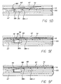
- the reciprocating pusher 16 is shown in its proximal most position with the knob 68 located proximally of the cantilever ramp 38.
- the tabs 58 n-1, n, n+1, ... of the reciprocating pusher are not in engagement with the clips 14 or the backstop 20.
- Tab 58 n fits within the U-shaped mid section 84 of the backstop 20 (see also FIG. 4).
- the tabs located distally of tab 58 n fit between the legs of the respective clips 14. The distance between the tabs and the clips in the start position may be adjusted to accommodate the extra distance that may be traveled by the staging bar for pushing the distalmost clip into the jaws of the device.
- Knob 68 also enters passage 45 between the cantilever ramp 38 and the common wall 26.
- the knob 68 has advanced into engagement with the distal ramp portion 44 of the cantilever ramp, deflecting it upward as the knob passes through passage 45.
- the knob has traveled completely past the cantilever ramp, which returns to its unflexed position.
- the reciprocating pusher advances each clip and the backstop forward until a distance of approximately one clip length is traveled. While the backstop is being pushed forward, the lateral wings 86 of the backstop are deflected inward by the ratcheting surfaces 100 on the side 98 of the housing. After one clip length is traveled, the lateral wings snap back into their unflexed condition, which supports the clips in their new position. Although not shown, the staging bar 18 has pushed the distal-most clip past the detent 32 into the clamping mechanism.
- the operator has begun to release the actuator and the reciprocating pusher 16 begins to retract.
- the knob 68 interfaces with the cantilever ramp 38 of the housing and begins to ride up the ramp portion 44. Since the ramp is supported beneath it by the clips, the reciprocating pusher is driven upward and the support spring 72 is deformed. This lifts the tabs 58 above the clips 14 and the backstop 20.
- knob 68 travels through passage 49 between the cantilever ramp and the upper wall 47 of the housing (see FIG. 5F).
- the knob 68 leaves the cantilever ramp and the support spring 72 returns the reciprocating pusher to its original position (see FIG. 5A).
- the staging bar 18 interfaces with a new distal-most clip to be advanced into the clamping mechanism.
- the present invention provides a clip advance that positively advances a stack of clips in such a manner as to substantially reduce or eliminate jamming or misfiring.
- each clip is individually supported and advanced by a respective tab.
- a mechanism is provided to disengage the tabs from the clips during resetting so that the tabs can be pulled back to reengage the next clips in sequence.
- the present invention also includes an improved backstop to prevent the clips from moving rearward after advancement.
Landscapes
- Health & Medical Sciences (AREA)
- Surgery (AREA)
- Life Sciences & Earth Sciences (AREA)
- Heart & Thoracic Surgery (AREA)
- Nuclear Medicine, Radiotherapy & Molecular Imaging (AREA)
- Vascular Medicine (AREA)
- Engineering & Computer Science (AREA)
- Biomedical Technology (AREA)
- Reproductive Health (AREA)
- Medical Informatics (AREA)
- Molecular Biology (AREA)
- Animal Behavior & Ethology (AREA)
- General Health & Medical Sciences (AREA)
- Public Health (AREA)
- Veterinary Medicine (AREA)
- Surgical Instruments (AREA)
Description
Claims (17)
- A clip advance (10) for sequentially advancing a plurality of surgical clips (14) in a surgical clip applier, comprising:wherein one of said pusher (16) and housing (12) has a rigid cam (66, 68) and the other of said pusher (16) and housing (12) has a cam surface (43), the cam (66, 68) and the cam surface (43) configured and arranged relative to each other such that, upon proximal movement of the pusher (16), the cam (66, 68) and the cam surface (43) interact to move the tabs (58) out of longitudinal contacting alignment with the clips (14) without deflecting the tabs (58) with respect to the pusher (16),a longitudinally extending housing (12) having a first channel for receiving the plurality of surgical clips (14); and a pusher (16) mounted in the housing (12) for reciprocating longitudinal movement adjacent the plurality of clips (14),the pusher (16) having a plurality of tabs (58) arranged to correspondingly engage and distally move respective ones of the plurality of clips (14) when said pusher (16) is moved distally;
characterized in that,
the cam surface (43) is on a deflectable member which is deflected by the rigid cam (66, 68) when the pusher (16) is moved distally. - The clip advance (10) of claim 1, wherein the deflectable member is a longitudinally extending cantilever ramp (38) that is fixed at its proximal end to the housing (12) and wherein the cam (66, 68) is a transversely extending knob on the pusher (16) that is in longitudinally contacting alignment with the cantilever ramp (38).
- The clip advance (10) of claim 2, wherein, upon distal movement of the pusher (16), the knob (66, 68) engages and deflects the cantilever ramp (38) out of the way as the knob (66, 68) passes by the cantilever ramp (38), and wherein, upon proximal movement of the pusher (16), the knob (66, 68) rides along the cantilever ramp (38), lifting the tabs (58) of the pusher (16) out of alignment with the clips (14).
- The clip advance (10) of claim 3, further comprising a biasing member that returns the tabs (58) of the pusher (16) into contacting longitudinal alignment with the clips (14) upon proximal disengagement of the knob (68) from the cantilever ramp (38).
- The clip advance (10) of claim 4, wherein the biasing member is a leaf spring fixed to the pusher (16).
- The clip advance (10) of claim 1, wherein the first channel (22) of the housing (12) defines a ratchet surface (100) and wherein the clip advance (10) further comprises a backstop (20) located in the first channel (22) of the housing (12), the backstop (20) having a deflectable wing (86) in engagement with the ratchet surface (100) such that distal movement of the backstop (20) causes the wing (86) to alternately flex inward as the wing (86) moves along the ratchet surface (100) and then flex outward after moving approximately one clip length.
- The clip advance (10) of claim 1, further comprising a staging bar (18) mounted to the reciprocating pusher (16), the staging bar (18) having a head (76) at its distal end for engaging a distal-most clip (14) in the first channel (22) of the housing (12).
- The clip advance (10) of claim 7, wherein the head (76) has a proximal ramp surface (80) configured to ride over one of said plurality of clips (14) upon proximal movement of the staging bar (18).
- The clip advance (10) of claim 7, wherein the staging bar (18) has a bend (82) located proximally of the head (76) that engages the housing (12) such that the housing (12) applies a biasing force, urging the head (76) of the staging bar (18) toward the first channel (22).
- The clip advance (10) of claim 1, wherein the housing (12) includes a detent (32) at its distal end (30) in contacting longitudinal alignment with the clips (14).
- The clip advance (10) of claim 10, wherein the detent (32) includes a distally extending cantilever arm (34) and a hook (36) at the distal end (30) of the cantilever arm (34), the hook (36) in contacting longitudinal alignment with the clips (14).
- A clip advance (10) for sequentially advancing a plurality of surgical clips (14) in a surgical clip applier, comprising:wherein one of said pusher (16) and housing has a cam surface (43) and the other of said pusher (16) and housing (12) has a cam (66, 68), the cam surface (43) and the cam (66, 68) configured and arranged relative to each other such that, upon proximal movement of the pusher (16), cam surface (43) and the cam (66, 68) interact to move the tabs (58) out of longitudinal contacting alignment with the clips (14) without deflecting the tabs (58) with respect to the pusher (16);a longitudinally extending housing (12) having a first channel (22), the first channel (22) for receiving the plurality of surgical clips (14); anda pusher (16) mounted in the housing (12) for reciprocating longitudinal movement adjacent the plurality of clips (14), the pusher (16) having a plurality of tabs (58) arranged to correspondingly engage and distally move respective ones of the plurality of clips (14) when said pusher (16) is moved distally;
characterized in that,
the housing (12) has an additional second channel (24), first and second channels (22, 24) are located in parallel alignment to one another; the pusher (16) is mounted in the second channel (24) of the housing (12); and, the cam surface (43) is provided by a deflectable member which is deflected by the cam (66, 68) when the pusher (16) is moved distally. - The clip advance (10) of claim 12, wherein the deflectable member is a longitudinally extending cantilever ramp (38) that is fixed at its proximal end to the housing (12) and wherein the cam (66, 68) is a transversely extending knob on the pusher (16) that is in longitudinally contacting alignment with the cantilever ramp (38).
- The clip advance (10) of claim 13, wherein, upon distal movement of the pusher (16), the knob (66, 68) engages and deflects the cantilever ramp (38) out of the way as the knob (66, 68) passes by the cantilever ramp (38), and wherein, upon proximal movement of the pusher (16), the knob (66, 68) rides along the cantilever ramp (38), lifting the tabs (58) of the pusher (16) out of alignment with the clips (14).
- The clip advance (10) of claim 14, further comprising a biasing member that returns the tabs (58) of the pusher (16) into contacting longitudinal alignment with the clips (14) upon proximal disengagement of the knob (66, 68) from the cantilever ramp (38).
- The clip advance (10) of claim 15, wherein the first channel (22) of the housing (12) defines a ratchet surface (100) and wherein the clip advance (10) further comprises a backstop (20) located in the first channel (22) of the housing (12), the backstop (20) having a deflectable wing (86) in engagement with the ratchet surface (100) such that distal movement of the backstop (20) causes the wing (86) to alternately flex inward as the wing (86) moves along the ratchet surface (100) and then flex outward after moving approximately one clip length.
- The clip advance (10) of claim 16, further comprising a staging bar (18) mounted to the reciprocating pusher (16), the staging bar (16) having a head (76) at its distal end for engaging a distal-most clip (14) in the first channel (22) of the housing (12).
Applications Claiming Priority (3)
| Application Number | Priority Date | Filing Date | Title |
|---|---|---|---|
| US08/308,084 US5626585A (en) | 1994-09-16 | 1994-09-16 | Ligating clip advance |
| US308084 | 1994-09-16 | ||
| PCT/US1995/010214 WO1996008203A1 (en) | 1994-09-16 | 1995-08-11 | Ligating clip advance |
Publications (2)
| Publication Number | Publication Date |
|---|---|
| EP0955907A1 EP0955907A1 (en) | 1999-11-17 |
| EP0955907B1 true EP0955907B1 (en) | 2002-01-02 |
Family
ID=23192476
Family Applications (1)
| Application Number | Title | Priority Date | Filing Date |
|---|---|---|---|
| EP95928817A Expired - Lifetime EP0955907B1 (en) | 1994-09-16 | 1995-08-11 | Ligating clip advance |
Country Status (6)
| Country | Link |
|---|---|
| US (1) | US5626585A (en) |
| EP (1) | EP0955907B1 (en) |
| CA (1) | CA2199968A1 (en) |
| DE (1) | DE69525083T2 (en) |
| ES (1) | ES2165922T3 (en) |
| WO (1) | WO1996008203A1 (en) |
Families Citing this family (179)
| Publication number | Priority date | Publication date | Assignee | Title |
|---|---|---|---|---|
| US5868759A (en) * | 1997-10-10 | 1999-02-09 | United States Surgical Corporation | Surgical clip applier |
| US6896683B1 (en) | 1999-01-25 | 2005-05-24 | Applied Material Resources Corporation | Surgical instrument with improved handle assembly |
| US6277131B1 (en) * | 2000-02-15 | 2001-08-21 | Microline, Inc | Ladder-type medical clip feeding mechanism |
| US6840945B2 (en) * | 2001-02-28 | 2005-01-11 | Microline, Inc. | Medical clip applier safety arrangement |
| US6306149B1 (en) * | 2000-02-15 | 2001-10-23 | Microline, Inc. | Medical clip device with cyclical pusher mechanism |
| US7141056B2 (en) * | 2000-02-15 | 2006-11-28 | Microline Pentax Inc. | Multiplier extension arrangement |
| US6632228B2 (en) * | 2000-08-23 | 2003-10-14 | Scimed Life System, Inc. | System, method, and apparatus for accurately deploying particular medical appliances at a target site |
| US6599298B1 (en) | 2000-10-23 | 2003-07-29 | Vitalitec International, S.A. | Automatic surgical clip applier |
| US6716226B2 (en) * | 2001-06-25 | 2004-04-06 | Inscope Development, Llc | Surgical clip |
| US6824547B2 (en) | 2001-07-13 | 2004-11-30 | Pilling Weck Incorporated | Endoscopic clip applier and method |
| US7179265B2 (en) * | 2001-08-21 | 2007-02-20 | Microline Pentax, Inc. | Reduced diameter clip applying arrangement |
| EP3170459A1 (en) | 2003-03-11 | 2017-05-24 | Covidien LP | Clip applying apparatus with angled jaw |
| US7461574B2 (en) * | 2003-04-28 | 2008-12-09 | Biomet Microfixation, Llc | Multiple screw delivery apparatus |
| EP1799120B1 (en) | 2004-09-23 | 2017-11-01 | Covidien LP | Clip applying apparatus and ligation clip |
| ES2616731T3 (en) | 2004-10-08 | 2017-06-14 | Covidien Lp | Apparatus for applying surgical bras |
| US8409222B2 (en) | 2004-10-08 | 2013-04-02 | Covidien Lp | Endoscopic surgical clip applier |
| WO2006042084A2 (en) | 2004-10-08 | 2006-04-20 | Tyco Healthcare Group, Lp | Endoscopic surgical clip applier |
| US7819886B2 (en) | 2004-10-08 | 2010-10-26 | Tyco Healthcare Group Lp | Endoscopic surgical clip applier |
| US9763668B2 (en) | 2004-10-08 | 2017-09-19 | Covidien Lp | Endoscopic surgical clip applier |
| US7731724B2 (en) * | 2005-04-14 | 2010-06-08 | Ethicon Endo-Surgery, Inc. | Surgical clip advancement and alignment mechanism |
| US8523882B2 (en) * | 2005-04-14 | 2013-09-03 | Ethicon Endo-Surgery, Inc. | Clip advancer mechanism with alignment features |
| US7261724B2 (en) * | 2005-04-14 | 2007-08-28 | Ethicon Endo-Surgery, Inc. | Surgical clip advancement mechanism |
| US8038686B2 (en) * | 2005-04-14 | 2011-10-18 | Ethicon Endo-Surgery, Inc. | Clip applier configured to prevent clip fallout |
| US20090014002A1 (en) * | 2005-04-14 | 2009-01-15 | Honeywell International Inc. | Air filter assembly |
| US7740641B2 (en) | 2005-04-14 | 2010-06-22 | Ethicon Endo-Surgery, Inc. | Clip applier with migrational resistance features |
| US7699860B2 (en) * | 2005-04-14 | 2010-04-20 | Ethicon Endo-Surgery, Inc. | Surgical clip |
| US7288098B2 (en) * | 2005-04-14 | 2007-10-30 | Ethicon Endo-Surgery, Inc. | Force limiting mechanism for medical instrument |
| US7686820B2 (en) * | 2005-04-14 | 2010-03-30 | Ethicon Endo-Surgery, Inc. | Surgical clip applier ratchet mechanism |
| US7297149B2 (en) | 2005-04-14 | 2007-11-20 | Ethicon Endo-Surgery, Inc. | Surgical clip applier methods |
| US20070049951A1 (en) * | 2005-08-25 | 2007-03-01 | Microline Pentax Inc. | Apparatus alignment device |
| US20070185504A1 (en) * | 2005-08-25 | 2007-08-09 | Microline Pentax, Inc. | Medical clip feeding mechanism |
| US7896895B2 (en) * | 2005-11-23 | 2011-03-01 | Ethicon Endo-Surgery, Inc. | Surgical clip and applier device and method of use |
| USD625009S1 (en) | 2006-03-24 | 2010-10-05 | Tyco Healthcare Group Lp | Surgical clip applier |
| USD629101S1 (en) | 2006-03-24 | 2010-12-14 | Tyco Healthcare Group Lp | Surgical clip applier |
| EP1913881B1 (en) | 2006-10-17 | 2014-06-11 | Covidien LP | Apparatus for applying surgical clips |
| US8382773B2 (en) | 2007-03-26 | 2013-02-26 | Covidien Lp | Endoscopic surgical clip applier |
| US7722628B2 (en) * | 2007-04-04 | 2010-05-25 | Ethicon Endo-Surgery, Inc. | Device for plicating and fastening gastric tissue |
| US7815653B2 (en) * | 2007-04-04 | 2010-10-19 | Ethicon Endo-Surgery, Inc. | Method for plicating and fastening gastric tissue |
| US7951159B2 (en) * | 2007-04-04 | 2011-05-31 | Ethicon Endo-Surgery, Inc. | Method for plicating and fastening gastric tissue |
| US7803166B2 (en) * | 2007-04-04 | 2010-09-28 | Ethicon Endo-Surgery, Inc. | Method for plicating and fastening gastric tissue |
| US7803165B2 (en) * | 2007-04-04 | 2010-09-28 | Ethicon Endo-Surgery, Inc. | Device for plicating and fastening gastric tissue |
| US7799040B2 (en) * | 2007-04-04 | 2010-09-21 | Ethicon Endo-Surgery, Inc. | Device for plicating and fastening gastric tissue |
| US8506580B2 (en) | 2007-04-11 | 2013-08-13 | Covidien Lp | Surgical clip applier |
| US8147504B2 (en) * | 2007-05-05 | 2012-04-03 | Medtronic, Inc. | Apparatus and methods for delivering fasteners during valve replacement |
| US8070036B1 (en) | 2007-09-06 | 2011-12-06 | Cardica, Inc | True multi-fire surgical stapler configured to fire staples of different sizes |
| US7988026B2 (en) | 2007-09-06 | 2011-08-02 | Cardica, Inc. | Endocutter with staple feed |
| US9168039B1 (en) | 2007-09-06 | 2015-10-27 | Cardica, Inc. | Surgical stapler with staples of different sizes |
| US8403956B1 (en) | 2007-09-06 | 2013-03-26 | Cardica, Inc. | Multiple-use surgical stapler |
| US20110208212A1 (en) | 2010-02-19 | 2011-08-25 | Zergiebel Earl M | Surgical clip applier |
| US8465502B2 (en) | 2008-08-25 | 2013-06-18 | Covidien Lp | Surgical clip applier and method of assembly |
| US8056565B2 (en) | 2008-08-25 | 2011-11-15 | Tyco Healthcare Group Lp | Surgical clip applier and method of assembly |
| US8267944B2 (en) | 2008-08-29 | 2012-09-18 | Tyco Healthcare Group Lp | Endoscopic surgical clip applier with lock out |
| US9358015B2 (en) | 2008-08-29 | 2016-06-07 | Covidien Lp | Endoscopic surgical clip applier with wedge plate |
| US8585717B2 (en) | 2008-08-29 | 2013-11-19 | Covidien Lp | Single stroke endoscopic surgical clip applier |
| US8409223B2 (en) | 2008-08-29 | 2013-04-02 | Covidien Lp | Endoscopic surgical clip applier with clip retention |
| US20100187283A1 (en) * | 2009-01-26 | 2010-07-29 | Lawrence Crainich | Method For Feeding Staples In a Low Profile Surgical Stapler |
| US20100191262A1 (en) * | 2009-01-26 | 2010-07-29 | Harris Jason L | Surgical stapler for applying a large staple through small delivery port and a method of using the stapler to secure a tissue fold |
| US8602286B2 (en) * | 2009-01-26 | 2013-12-10 | Ethicon Endo-Surgery, Inc. | Apparatus for feeding staples in a low profile surgical stapler |
| US8801732B2 (en) * | 2009-01-26 | 2014-08-12 | Ethicon Endo-Surgery, Inc. | Surgical stapler to secure a tissue fold |
| US9713471B2 (en) | 2009-01-26 | 2017-07-25 | Ethicon Endo-Surgery, Inc. | Surgical device with tandem fasteners |
| US8469252B2 (en) | 2009-01-26 | 2013-06-25 | Ethicon Endo-Surgery, Inc. | Surgical stapler fastening device with adjustable anvil |
| US20100187285A1 (en) * | 2009-01-26 | 2010-07-29 | Harris Jason L | Surgical stapler for applying a large staple though a small delivery port and a method of using the stapler to secure a tissue fold |
| US9713468B2 (en) | 2009-01-26 | 2017-07-25 | Ethicon Endo-Surgery, Inc. | Surgical stapler for applying a large staple through a small delivery port and a method of using the stapler to secure a tissue fold |
| US20100191255A1 (en) * | 2009-01-26 | 2010-07-29 | Lawrence Crainich | Method for Applying A Surgical Staple |
| US8439244B2 (en) | 2010-01-20 | 2013-05-14 | Ethicon Endo-Surgery, Inc. | Surgical stapler fastening device with movable anvil |
| US8453905B2 (en) | 2009-01-26 | 2013-06-04 | Ethicon Endo-Surgery, Inc. | Surgical fastener for applying a large staple through a small delivery port |
| DE102009018820A1 (en) | 2009-04-24 | 2010-10-28 | Aesculap Ag | Magazine with a variety of C-shaped ligature clips |
| DE202009006114U1 (en) | 2009-04-24 | 2009-07-02 | Aesculap Ag | Magazine with a variety of C-shaped ligature clips |
| DE102009018821A1 (en) * | 2009-04-24 | 2010-10-28 | Aesculap Ag | Surgical instrument for applying ligature clips |
| DE102009018819A1 (en) * | 2009-04-24 | 2010-10-28 | Aesculap Ag | Surgical instrument for applying ligature clips |
| US8631992B1 (en) | 2009-05-03 | 2014-01-21 | Cardica, Inc. | Feeder belt with padded staples for true multi-fire surgical stapler |
| US8267945B2 (en) * | 2009-10-09 | 2012-09-18 | Ethicon Endo-Surgery, Inc. | Clip advancer with lockout mechanism |
| US8262679B2 (en) * | 2009-10-09 | 2012-09-11 | Ethicon Endo-Surgery, Inc. | Clip advancer |
| US8734469B2 (en) * | 2009-10-13 | 2014-05-27 | Covidien Lp | Suture clip applier |
| US9186136B2 (en) | 2009-12-09 | 2015-11-17 | Covidien Lp | Surgical clip applier |
| US8545486B2 (en) | 2009-12-15 | 2013-10-01 | Covidien Lp | Surgical clip applier |
| US8403945B2 (en) | 2010-02-25 | 2013-03-26 | Covidien Lp | Articulating endoscopic surgical clip applier |
| US9597089B2 (en) | 2010-03-10 | 2017-03-21 | Conmed Corporation | Surgical clips for laparoscopic procedures |
| WO2011127137A1 (en) | 2010-04-06 | 2011-10-13 | Pavel Menn | Articulating steerable clip applier for laparoscopic procedures |
| US8439246B1 (en) | 2010-07-20 | 2013-05-14 | Cardica, Inc. | Surgical stapler with cartridge-adjustable clamp gap |
| US8403946B2 (en) | 2010-07-28 | 2013-03-26 | Covidien Lp | Articulating clip applier cartridge |
| US8968337B2 (en) | 2010-07-28 | 2015-03-03 | Covidien Lp | Articulating clip applier |
| US9011464B2 (en) | 2010-11-02 | 2015-04-21 | Covidien Lp | Self-centering clip and jaw |
| US9186153B2 (en) | 2011-01-31 | 2015-11-17 | Covidien Lp | Locking cam driver and jaw assembly for clip applier |
| DE102011001706A1 (en) | 2011-03-31 | 2012-10-04 | Aesculap Ag | Surgical clip applicator |
| US8636189B1 (en) | 2011-04-19 | 2014-01-28 | Cardica, Inc. | Active wedge for surgical stapler |
| US9655615B2 (en) | 2011-04-19 | 2017-05-23 | Dextera Surgical Inc. | Active wedge and I-beam for surgical stapler |
| US8631990B1 (en) | 2011-04-25 | 2014-01-21 | Cardica, Inc. | Staple trap for surgical stapler |
| US9320519B1 (en) | 2011-04-26 | 2016-04-26 | Cardica, Inc. | Single-trigger clamping and firing of surgical stapler |
| US9155536B1 (en) | 2011-04-26 | 2015-10-13 | Cardica, Inc. | Circular stapler |
| US9775623B2 (en) | 2011-04-29 | 2017-10-03 | Covidien Lp | Surgical clip applier including clip relief feature |
| JP6129859B2 (en) | 2011-10-19 | 2017-05-17 | エシコン・エンド−サージェリィ・インコーポレイテッドEthicon Endo−Surgery,Inc. | Clip applier adapted for use with surgical robots |
| US20130131697A1 (en) | 2011-11-21 | 2013-05-23 | Covidien Lp | Surgical clip applier |
| US9364239B2 (en) | 2011-12-19 | 2016-06-14 | Covidien Lp | Jaw closure mechanism for a surgical clip applier |
| US9364216B2 (en) | 2011-12-29 | 2016-06-14 | Covidien Lp | Surgical clip applier with integrated clip counter |
| US9084600B1 (en) | 2012-02-17 | 2015-07-21 | Cardica, Inc. | Anvil-side staple trap |
| US8992547B2 (en) | 2012-03-21 | 2015-03-31 | Ethicon Endo-Surgery, Inc. | Methods and devices for creating tissue plications |
| US9408610B2 (en) | 2012-05-04 | 2016-08-09 | Covidien Lp | Surgical clip applier with dissector |
| US9532787B2 (en) | 2012-05-31 | 2017-01-03 | Covidien Lp | Endoscopic clip applier |
| US9408605B1 (en) | 2012-07-12 | 2016-08-09 | Cardica, Inc. | Single-trigger clamping and firing of surgical stapler |
| US9113892B2 (en) | 2013-01-08 | 2015-08-25 | Covidien Lp | Surgical clip applier |
| US9968362B2 (en) | 2013-01-08 | 2018-05-15 | Covidien Lp | Surgical clip applier |
| US9750500B2 (en) | 2013-01-18 | 2017-09-05 | Covidien Lp | Surgical clip applier |
| US20150374392A1 (en) | 2013-05-14 | 2015-12-31 | Mubashir H. Khan | Endoscopic snare combined with a clip applier |
| US11426176B2 (en) | 2013-05-14 | 2022-08-30 | Mubashir H. Khan | Cartridge with multi-clip dispensing provisions |
| US10524786B2 (en) | 2013-05-14 | 2020-01-07 | Mubashir H. Khan | Spring-closing endoscopic clip where the spring action can also reverse the clip prior anytime before full ejection |
| US9775624B2 (en) | 2013-08-27 | 2017-10-03 | Covidien Lp | Surgical clip applier |
| ES2806279T3 (en) | 2014-04-28 | 2021-02-17 | Aesculap Ag | Stem medical instrument with a support plate / bridge on the retention rail |
| US10702278B2 (en) | 2014-12-02 | 2020-07-07 | Covidien Lp | Laparoscopic surgical ligation clip applier |
| US9931124B2 (en) | 2015-01-07 | 2018-04-03 | Covidien Lp | Reposable clip applier |
| WO2016112509A1 (en) | 2015-01-15 | 2016-07-21 | Covidien Lp | Endoscopic reposable surgical clip applier |
| US10292712B2 (en) | 2015-01-28 | 2019-05-21 | Covidien Lp | Surgical clip applier with integrated cutter |
| US10159491B2 (en) | 2015-03-10 | 2018-12-25 | Covidien Lp | Endoscopic reposable surgical clip applier |
| WO2016206015A1 (en) * | 2015-06-24 | 2016-12-29 | Covidien Lp | Surgical clip applier with multiple clip feeding mechanism |
| CN108348259B (en) | 2015-11-03 | 2020-12-11 | 柯惠有限合伙公司 | Endoscopic surgical clip applier |
| US10390831B2 (en) | 2015-11-10 | 2019-08-27 | Covidien Lp | Endoscopic reposable surgical clip applier |
| AU2015414380B2 (en) | 2015-11-10 | 2020-10-15 | Covidien Lp | Endoscopic reposable surgical clip applier |
| WO2017079890A1 (en) | 2015-11-10 | 2017-05-18 | Covidien Lp | Endoscopic reposable surgical clip applier |
| US10932793B2 (en) | 2016-01-11 | 2021-03-02 | Covidien Lp | Endoscopic reposable surgical clip applier |
| AU2016388454A1 (en) | 2016-01-18 | 2018-07-19 | Covidien Lp | Endoscopic surgical clip applier |
| CA2958160A1 (en) | 2016-02-24 | 2017-08-24 | Covidien Lp | Endoscopic reposable surgical clip applier |
| US10806464B2 (en) | 2016-08-11 | 2020-10-20 | Covidien Lp | Endoscopic surgical clip applier and clip applying systems |
| US11071553B2 (en) | 2016-08-25 | 2021-07-27 | Covidien Lp | Endoscopic surgical clip applier and clip applying systems |
| US10639044B2 (en) | 2016-10-31 | 2020-05-05 | Covidien Lp | Ligation clip module and clip applier |
| US10660651B2 (en) | 2016-10-31 | 2020-05-26 | Covidien Lp | Endoscopic reposable surgical clip applier |
| US10492795B2 (en) | 2016-11-01 | 2019-12-03 | Covidien Lp | Endoscopic surgical clip applier |
| US10426489B2 (en) | 2016-11-01 | 2019-10-01 | Covidien Lp | Endoscopic reposable surgical clip applier |
| US10610236B2 (en) | 2016-11-01 | 2020-04-07 | Covidien Lp | Endoscopic reposable surgical clip applier |
| US10709455B2 (en) | 2017-02-02 | 2020-07-14 | Covidien Lp | Endoscopic surgical clip applier |
| US10758244B2 (en) | 2017-02-06 | 2020-09-01 | Covidien Lp | Endoscopic surgical clip applier |
| EP3576643B1 (en) | 2017-02-06 | 2022-04-06 | Covidien LP | Surgical clip applier with user feedback feature |
| US10660725B2 (en) | 2017-02-14 | 2020-05-26 | Covidien Lp | Endoscopic surgical clip applier including counter assembly |
| US10603038B2 (en) | 2017-02-22 | 2020-03-31 | Covidien Lp | Surgical clip applier including inserts for jaw assembly |
| US11583291B2 (en) | 2017-02-23 | 2023-02-21 | Covidien Lp | Endoscopic surgical clip applier |
| US10548602B2 (en) | 2017-02-23 | 2020-02-04 | Covidien Lp | Endoscopic surgical clip applier |
| CN116784923A (en) | 2017-03-21 | 2023-09-22 | 泰利福医疗公司 | Clip applier with stabilizing member |
| US11607227B2 (en) | 2017-03-21 | 2023-03-21 | Teleflex Medical Incorporated | Surgical clip and clip applier |
| WO2018175626A1 (en) | 2017-03-21 | 2018-09-27 | Teleflex Medical Incorporated | Clip applier with stabilizing member |
| WO2018175650A1 (en) | 2017-03-21 | 2018-09-27 | Teleflex Medical Incorporated | Flexible stabilizing member for a clip applier |
| JP6876821B2 (en) | 2017-03-21 | 2021-05-26 | テレフレックス メディカル インコーポレイテッド | Clip applier with replaceable tip |
| US10675043B2 (en) | 2017-05-04 | 2020-06-09 | Covidien Lp | Reposable multi-fire surgical clip applier |
| US10722235B2 (en) | 2017-05-11 | 2020-07-28 | Covidien Lp | Spring-release surgical clip |
| US10660723B2 (en) | 2017-06-30 | 2020-05-26 | Covidien Lp | Endoscopic reposable surgical clip applier |
| US10639032B2 (en) | 2017-06-30 | 2020-05-05 | Covidien Lp | Endoscopic surgical clip applier including counter assembly |
| US10675112B2 (en) | 2017-08-07 | 2020-06-09 | Covidien Lp | Endoscopic surgical clip applier including counter assembly |
| US10932790B2 (en) | 2017-08-08 | 2021-03-02 | Covidien Lp | Geared actuation mechanism and surgical clip applier including the same |
| US10863992B2 (en) | 2017-08-08 | 2020-12-15 | Covidien Lp | Endoscopic surgical clip applier |
| US10786262B2 (en) | 2017-08-09 | 2020-09-29 | Covidien Lp | Endoscopic reposable surgical clip applier |
| US10786263B2 (en) | 2017-08-15 | 2020-09-29 | Covidien Lp | Endoscopic reposable surgical clip applier |
| US10835341B2 (en) | 2017-09-12 | 2020-11-17 | Covidien Lp | Endoscopic surgical clip applier and handle assemblies for use therewith |
| US10835260B2 (en) | 2017-09-13 | 2020-11-17 | Covidien Lp | Endoscopic surgical clip applier and handle assemblies for use therewith |
| US10653429B2 (en) | 2017-09-13 | 2020-05-19 | Covidien Lp | Endoscopic surgical clip applier |
| US10758245B2 (en) | 2017-09-13 | 2020-09-01 | Covidien Lp | Clip counting mechanism for surgical clip applier |
| US10932791B2 (en) | 2017-11-03 | 2021-03-02 | Covidien Lp | Reposable multi-fire surgical clip applier |
| US11116513B2 (en) | 2017-11-03 | 2021-09-14 | Covidien Lp | Modular surgical clip cartridge |
| US10828036B2 (en) | 2017-11-03 | 2020-11-10 | Covidien Lp | Endoscopic surgical clip applier and handle assemblies for use therewith |
| US10945734B2 (en) | 2017-11-03 | 2021-03-16 | Covidien Lp | Rotation knob assemblies and surgical instruments including the same |
| US11376015B2 (en) | 2017-11-03 | 2022-07-05 | Covidien Lp | Endoscopic surgical clip applier and handle assemblies for use therewith |
| US10722236B2 (en) | 2017-12-12 | 2020-07-28 | Covidien Lp | Endoscopic reposable surgical clip applier |
| US10849630B2 (en) | 2017-12-13 | 2020-12-01 | Covidien Lp | Reposable multi-fire surgical clip applier |
| US10743887B2 (en) | 2017-12-13 | 2020-08-18 | Covidien Lp | Reposable multi-fire surgical clip applier |
| US10959737B2 (en) | 2017-12-13 | 2021-03-30 | Covidien Lp | Reposable multi-fire surgical clip applier |
| US11051827B2 (en) | 2018-01-16 | 2021-07-06 | Covidien Lp | Endoscopic surgical instrument and handle assemblies for use therewith |
| US10993721B2 (en) | 2018-04-25 | 2021-05-04 | Covidien Lp | Surgical clip applier |
| US10786273B2 (en) | 2018-07-13 | 2020-09-29 | Covidien Lp | Rotation knob assemblies for handle assemblies |
| US11259887B2 (en) | 2018-08-10 | 2022-03-01 | Covidien Lp | Feedback mechanisms for handle assemblies |
| US11278267B2 (en) | 2018-08-13 | 2022-03-22 | Covidien Lp | Latch assemblies and surgical instruments including the same |
| US11219463B2 (en) | 2018-08-13 | 2022-01-11 | Covidien Lp | Bilateral spring for surgical instruments and surgical instruments including the same |
| US11253267B2 (en) | 2018-08-13 | 2022-02-22 | Covidien Lp | Friction reduction mechanisms for handle assemblies |
| US11051828B2 (en) | 2018-08-13 | 2021-07-06 | Covidien Lp | Rotation knob assemblies and surgical instruments including same |
| US11246601B2 (en) | 2018-08-13 | 2022-02-15 | Covidien Lp | Elongated assemblies for surgical clip appliers and surgical clip appliers incorporating the same |
| US11344316B2 (en) | 2018-08-13 | 2022-05-31 | Covidien Lp | Elongated assemblies for surgical clip appliers and surgical clip appliers incorporating the same |
| US11033256B2 (en) | 2018-08-13 | 2021-06-15 | Covidien Lp | Linkage assembly for reusable surgical handle assemblies |
| US11147566B2 (en) | 2018-10-01 | 2021-10-19 | Covidien Lp | Endoscopic surgical clip applier |
| US11524398B2 (en) | 2019-03-19 | 2022-12-13 | Covidien Lp | Gear drive mechanisms for surgical instruments |
| US11779340B2 (en) | 2020-01-02 | 2023-10-10 | Covidien Lp | Ligation clip loading device |
| US11723669B2 (en) | 2020-01-08 | 2023-08-15 | Covidien Lp | Clip applier with clip cartridge interface |
| CN113813003A (en) * | 2021-11-19 | 2021-12-21 | 杭州康基医疗器械有限公司 | Feeding mechanism applied to repeating metal clamp |
| CN113796916A (en) * | 2021-11-19 | 2021-12-17 | 杭州康基医疗器械有限公司 | Repeating metal clamp |
Family Cites Families (37)
| Publication number | Priority date | Publication date | Assignee | Title |
|---|---|---|---|---|
| US3098232A (en) * | 1960-02-24 | 1963-07-23 | Ernest C Wood | Surgical clip applicator |
| US3086208A (en) * | 1960-10-06 | 1963-04-23 | Ethicon Inc | Surgical clip assembly |
| US3638847A (en) * | 1970-07-06 | 1972-02-01 | United States Surgical Corp | Ratchet-driven cartridge for surgical instruments |
| GB1456901A (en) * | 1973-01-20 | 1976-12-01 | Akiyama T | Apparatus for closing a blood vessel |
| US4452376A (en) * | 1977-08-05 | 1984-06-05 | Charles H. Klieman | Hemostatic clip applicator |
| US4226239A (en) * | 1978-01-31 | 1980-10-07 | Kli, Inc. | Surgical ligating instrument and method |
| US4296751A (en) * | 1979-08-02 | 1981-10-27 | Blake Joseph W Iii | Surgical device |
| US4452357A (en) * | 1980-07-22 | 1984-06-05 | Charles H. Klieman | Surgical stapler |
| US4393883A (en) * | 1980-11-03 | 1983-07-19 | Medtronic, Inc. | Single pass A-V lead |
| US4500024A (en) * | 1980-11-19 | 1985-02-19 | Ethicon, Inc. | Multiple clip applier |
| US4430997A (en) * | 1980-11-19 | 1984-02-14 | Ethicon, Inc. | Multiple clip applier |
| US4478220A (en) * | 1982-02-05 | 1984-10-23 | Ethicon, Inc. | Ligating clip cartridge |
| US4509518A (en) * | 1982-02-17 | 1985-04-09 | United States Surgical Corporation | Apparatus for applying surgical clips |
| US4470532A (en) * | 1982-07-21 | 1984-09-11 | Minnesota Mining And Manufacturing Company | Medical stapling device |
| US4674504A (en) * | 1982-10-06 | 1987-06-23 | Klieman Charles H | Spring activated hemostatic clip applicator |
| US4616650A (en) * | 1984-07-27 | 1986-10-14 | United States Surgical Corporation | Apparatus for applying surgical clips |
| GB8620560D0 (en) * | 1986-08-23 | 1986-10-01 | Femcare Ltd | Applicator |
| US4850355A (en) * | 1987-04-06 | 1989-07-25 | Richard-Allan Medical Industries, Inc. | Hemostatic clip applicator for applying multiple hemostatic clips |
| US5084057A (en) * | 1989-07-18 | 1992-01-28 | United States Surgical Corporation | Apparatus and method for applying surgical clips in laparoscopic or endoscopic procedures |
| US5100420A (en) * | 1989-07-18 | 1992-03-31 | United States Surgical Corporation | Apparatus and method for applying surgical clips in laparoscopic or endoscopic procedures |
| US5030226A (en) * | 1988-01-15 | 1991-07-09 | United States Surgical Corporation | Surgical clip applicator |
| US4919320A (en) * | 1988-03-07 | 1990-04-24 | Technalytics, Inc. | Surgical stapler |
| US5151101A (en) * | 1988-06-02 | 1992-09-29 | Circon Corporation | System for disconnectably mounting an endoscope sheath with an endoscope tool |
| FR2637489A1 (en) * | 1988-10-07 | 1990-04-13 | Lachkar Alain | AUTOMATIC CLIPS CLIP |
| US5040715B1 (en) * | 1989-05-26 | 1994-04-05 | United States Surgical Corp | Apparatus and method for placing staples in laparoscopic or endoscopic procedures |
| US5382254A (en) * | 1989-07-18 | 1995-01-17 | United States Surgical Corporation | Actuating handle for surgical instruments |
| US5282807A (en) * | 1990-11-05 | 1994-02-01 | Knoepfler Dennis J | Automatic stapler for laparoscopic procedure with selective cutter, nontraumatic jaws and suction irrigator |
| US5171247A (en) * | 1991-04-04 | 1992-12-15 | Ethicon, Inc. | Endoscopic multiple ligating clip applier with rotating shaft |
| US5171249A (en) * | 1991-04-04 | 1992-12-15 | Ethicon, Inc. | Endoscopic multiple ligating clip applier |
| DE4114311A1 (en) * | 1991-05-02 | 1992-11-12 | Harald Heidmueller | EXTRACTOR |
| US5356064A (en) * | 1991-10-18 | 1994-10-18 | United States Surgical Corporation | Apparatus and method for applying surgical staples to attach an object to body tissue |
| US5289963A (en) * | 1991-10-18 | 1994-03-01 | United States Surgical Corporation | Apparatus and method for applying surgical staples to attach an object to body tissue |
| US5314424A (en) * | 1992-04-06 | 1994-05-24 | United States Surgical Corporation | Surgical instrument locking mechanism |
| US5192288A (en) * | 1992-05-26 | 1993-03-09 | Origin Medsystems, Inc. | Surgical clip applier |
| US5300081A (en) * | 1992-10-09 | 1994-04-05 | United States Surgical Corporation | Surgical clip applier having clip advancement control |
| US5409498A (en) * | 1992-11-05 | 1995-04-25 | Ethicon, Inc. | Rotatable articulating endoscopic fastening instrument |
| US5382255A (en) * | 1993-01-08 | 1995-01-17 | United States Surgical Corporation | Apparatus and method for assembly of surgical instruments |
-
1994
- 1994-09-16 US US08/308,084 patent/US5626585A/en not_active Expired - Lifetime
-
1995
- 1995-08-11 CA CA002199968A patent/CA2199968A1/en not_active Abandoned
- 1995-08-11 DE DE69525083T patent/DE69525083T2/en not_active Expired - Lifetime
- 1995-08-11 EP EP95928817A patent/EP0955907B1/en not_active Expired - Lifetime
- 1995-08-11 WO PCT/US1995/010214 patent/WO1996008203A1/en active IP Right Grant
- 1995-08-11 ES ES95928817T patent/ES2165922T3/en not_active Expired - Lifetime
Also Published As
| Publication number | Publication date |
|---|---|
| DE69525083D1 (en) | 2002-02-28 |
| ES2165922T3 (en) | 2002-04-01 |
| CA2199968A1 (en) | 1996-03-21 |
| EP0955907A1 (en) | 1999-11-17 |
| WO1996008203A1 (en) | 1996-03-21 |
| US5626585A (en) | 1997-05-06 |
| DE69525083T2 (en) | 2002-08-01 |
Similar Documents
| Publication | Publication Date | Title |
|---|---|---|
| EP0955907B1 (en) | Ligating clip advance | |
| EP1805849B1 (en) | Apparatus for applying surgical clips | |
| US5718359A (en) | Surgical stapler with lockout mechanism | |
| EP1024751B1 (en) | Surgical clip applier | |
| US5415334A (en) | Surgical stapler and staple cartridge | |
| US5049152A (en) | Hemostatic clip applicator | |
| EP2485659B1 (en) | Clip advancer with lockout mechanism | |
| US4616650A (en) | Apparatus for applying surgical clips | |
| EP0537453B1 (en) | Anvil for surgical staplers | |
| US6681978B2 (en) | Surgical stapler | |
| EP0118262B1 (en) | Stapler including ratchet means for preventing double feeding of staples | |
| US5988479A (en) | Apparatus for applying surgical fasteners | |
| EP1764044B1 (en) | Clip applier with migrational resistance features | |
| EP0121474B1 (en) | Safety apparatus for surgical occluding and cutting device | |
| US4576165A (en) | Surgical ligation and cutting device with safety means | |
| JP2004344659A (en) | Surgical stapler having single lockout mechanism for erroneous firing prevention | |
| CA1247965A (en) | Method and apparatus for surgical occluding and cutting | |
| JPH012640A (en) | Hemostatic forceps applicator for attaching multiple hemostatic forceps |
Legal Events
| Date | Code | Title | Description |
|---|---|---|---|
| PUAI | Public reference made under article 153(3) epc to a published international application that has entered the european phase |
Free format text: ORIGINAL CODE: 0009012 |
|
| 17P | Request for examination filed |
Effective date: 19970317 |
|
| AK | Designated contracting states |
Kind code of ref document: A1 Designated state(s): DE ES FR GB IT |
|
| 17Q | First examination report despatched |
Effective date: 19991214 |
|
| GRAG | Despatch of communication of intention to grant |
Free format text: ORIGINAL CODE: EPIDOS AGRA |
|
| GRAG | Despatch of communication of intention to grant |
Free format text: ORIGINAL CODE: EPIDOS AGRA |
|
| GRAH | Despatch of communication of intention to grant a patent |
Free format text: ORIGINAL CODE: EPIDOS IGRA |
|
| GRAH | Despatch of communication of intention to grant a patent |
Free format text: ORIGINAL CODE: EPIDOS IGRA |
|
| GRAA | (expected) grant |
Free format text: ORIGINAL CODE: 0009210 |
|
| REG | Reference to a national code |
Ref country code: GB Ref legal event code: IF02 |
|
| AK | Designated contracting states |
Kind code of ref document: B1 Designated state(s): DE ES FR GB IT |
|
| REF | Corresponds to: |
Ref document number: 69525083 Country of ref document: DE Date of ref document: 20020228 |
|
| REG | Reference to a national code |
Ref country code: ES Ref legal event code: FG2A Ref document number: 2165922 Country of ref document: ES Kind code of ref document: T3 |
|
| ET | Fr: translation filed | ||
| PLBE | No opposition filed within time limit |
Free format text: ORIGINAL CODE: 0009261 |
|
| STAA | Information on the status of an ep patent application or granted ep patent |
Free format text: STATUS: NO OPPOSITION FILED WITHIN TIME LIMIT |
|
| 26N | No opposition filed | ||
| PGFP | Annual fee paid to national office [announced via postgrant information from national office to epo] |
Ref country code: ES Payment date: 20110826 Year of fee payment: 17 |
|
| PGFP | Annual fee paid to national office [announced via postgrant information from national office to epo] |
Ref country code: IT Payment date: 20110826 Year of fee payment: 17 |
|
| PG25 | Lapsed in a contracting state [announced via postgrant information from national office to epo] |
Ref country code: IT Free format text: LAPSE BECAUSE OF NON-PAYMENT OF DUE FEES Effective date: 20120811 |
|
| REG | Reference to a national code |
Ref country code: ES Ref legal event code: FD2A Effective date: 20131021 |
|
| PG25 | Lapsed in a contracting state [announced via postgrant information from national office to epo] |
Ref country code: ES Free format text: LAPSE BECAUSE OF NON-PAYMENT OF DUE FEES Effective date: 20120812 |
|
| PGFP | Annual fee paid to national office [announced via postgrant information from national office to epo] |
Ref country code: DE Payment date: 20140827 Year of fee payment: 20 |
|
| PGFP | Annual fee paid to national office [announced via postgrant information from national office to epo] |
Ref country code: GB Payment date: 20140827 Year of fee payment: 20 Ref country code: FR Payment date: 20140818 Year of fee payment: 20 |
|
| REG | Reference to a national code |
Ref country code: DE Ref legal event code: R071 Ref document number: 69525083 Country of ref document: DE |
|
| REG | Reference to a national code |
Ref country code: GB Ref legal event code: PE20 Expiry date: 20150810 |
|
| PG25 | Lapsed in a contracting state [announced via postgrant information from national office to epo] |
Ref country code: GB Free format text: LAPSE BECAUSE OF EXPIRATION OF PROTECTION Effective date: 20150810 |