EP0911234A2 - Vehicle dynamic control system - Google Patents
Vehicle dynamic control system Download PDFInfo
- Publication number
- EP0911234A2 EP0911234A2 EP98308597A EP98308597A EP0911234A2 EP 0911234 A2 EP0911234 A2 EP 0911234A2 EP 98308597 A EP98308597 A EP 98308597A EP 98308597 A EP98308597 A EP 98308597A EP 0911234 A2 EP0911234 A2 EP 0911234A2
- Authority
- EP
- European Patent Office
- Prior art keywords
- vehicle
- curve
- differential
- yaw rate
- vehicle movement
- Prior art date
- Legal status (The legal status is an assumption and is not a legal conclusion. Google has not performed a legal analysis and makes no representation as to the accuracy of the status listed.)
- Granted
Links
- 238000009826 distribution Methods 0.000 claims abstract description 41
- 230000002349 favourable effect Effects 0.000 claims abstract description 18
- 230000000087 stabilizing effect Effects 0.000 claims abstract description 7
- 238000012546 transfer Methods 0.000 description 21
- 230000001133 acceleration Effects 0.000 description 13
- 238000012937 correction Methods 0.000 description 13
- 238000001514 detection method Methods 0.000 description 8
- 238000002474 experimental method Methods 0.000 description 8
- 230000006870 function Effects 0.000 description 8
- 150000001875 compounds Chemical class 0.000 description 7
- 238000012545 processing Methods 0.000 description 6
- 230000004044 response Effects 0.000 description 4
- 230000014509 gene expression Effects 0.000 description 3
- 230000007935 neutral effect Effects 0.000 description 3
- 230000009467 reduction Effects 0.000 description 3
- 230000035945 sensitivity Effects 0.000 description 3
- 230000003313 weakening effect Effects 0.000 description 3
- 230000005484 gravity Effects 0.000 description 2
- 239000004973 liquid crystal related substance Substances 0.000 description 2
- 230000004043 responsiveness Effects 0.000 description 2
- 238000005728 strengthening Methods 0.000 description 2
- NAWXUBYGYWOOIX-SFHVURJKSA-N (2s)-2-[[4-[2-(2,4-diaminoquinazolin-6-yl)ethyl]benzoyl]amino]-4-methylidenepentanedioic acid Chemical compound C1=CC2=NC(N)=NC(N)=C2C=C1CCC1=CC=C(C(=O)N[C@@H](CC(=C)C(O)=O)C(O)=O)C=C1 NAWXUBYGYWOOIX-SFHVURJKSA-N 0.000 description 1
- 230000002159 abnormal effect Effects 0.000 description 1
- 230000008859 change Effects 0.000 description 1
- 238000006243 chemical reaction Methods 0.000 description 1
- 239000002131 composite material Substances 0.000 description 1
- 238000010276 construction Methods 0.000 description 1
- 230000008878 coupling Effects 0.000 description 1
- 238000010168 coupling process Methods 0.000 description 1
- 238000005859 coupling reaction Methods 0.000 description 1
- 230000001934 delay Effects 0.000 description 1
- 238000010586 diagram Methods 0.000 description 1
- 230000000694 effects Effects 0.000 description 1
- 230000008030 elimination Effects 0.000 description 1
- 238000003379 elimination reaction Methods 0.000 description 1
- 239000012530 fluid Substances 0.000 description 1
- 239000000446 fuel Substances 0.000 description 1
- 230000001788 irregular Effects 0.000 description 1
- 238000012986 modification Methods 0.000 description 1
- 230000004048 modification Effects 0.000 description 1
- 230000002093 peripheral effect Effects 0.000 description 1
- 239000013589 supplement Substances 0.000 description 1
- 230000007704 transition Effects 0.000 description 1
Images


Classifications
-
- B—PERFORMING OPERATIONS; TRANSPORTING
- B60—VEHICLES IN GENERAL
- B60T—VEHICLE BRAKE CONTROL SYSTEMS OR PARTS THEREOF; BRAKE CONTROL SYSTEMS OR PARTS THEREOF, IN GENERAL; ARRANGEMENT OF BRAKING ELEMENTS ON VEHICLES IN GENERAL; PORTABLE DEVICES FOR PREVENTING UNWANTED MOVEMENT OF VEHICLES; VEHICLE MODIFICATIONS TO FACILITATE COOLING OF BRAKES
- B60T8/00—Arrangements for adjusting wheel-braking force to meet varying vehicular or ground-surface conditions, e.g. limiting or varying distribution of braking force
- B60T8/17—Using electrical or electronic regulation means to control braking
- B60T8/1755—Brake regulation specially adapted to control the stability of the vehicle, e.g. taking into account yaw rate or transverse acceleration in a curve
-
- B—PERFORMING OPERATIONS; TRANSPORTING
- B60—VEHICLES IN GENERAL
- B60T—VEHICLE BRAKE CONTROL SYSTEMS OR PARTS THEREOF; BRAKE CONTROL SYSTEMS OR PARTS THEREOF, IN GENERAL; ARRANGEMENT OF BRAKING ELEMENTS ON VEHICLES IN GENERAL; PORTABLE DEVICES FOR PREVENTING UNWANTED MOVEMENT OF VEHICLES; VEHICLE MODIFICATIONS TO FACILITATE COOLING OF BRAKES
- B60T2201/00—Particular use of vehicle brake systems; Special systems using also the brakes; Special software modules within the brake system controller
- B60T2201/14—Electronic locking-differential
-
- B—PERFORMING OPERATIONS; TRANSPORTING
- B60—VEHICLES IN GENERAL
- B60T—VEHICLE BRAKE CONTROL SYSTEMS OR PARTS THEREOF; BRAKE CONTROL SYSTEMS OR PARTS THEREOF, IN GENERAL; ARRANGEMENT OF BRAKING ELEMENTS ON VEHICLES IN GENERAL; PORTABLE DEVICES FOR PREVENTING UNWANTED MOVEMENT OF VEHICLES; VEHICLE MODIFICATIONS TO FACILITATE COOLING OF BRAKES
- B60T2201/00—Particular use of vehicle brake systems; Special systems using also the brakes; Special software modules within the brake system controller
- B60T2201/16—Curve braking control, e.g. turn control within ABS control algorithm
-
- B—PERFORMING OPERATIONS; TRANSPORTING
- B60—VEHICLES IN GENERAL
- B60T—VEHICLE BRAKE CONTROL SYSTEMS OR PARTS THEREOF; BRAKE CONTROL SYSTEMS OR PARTS THEREOF, IN GENERAL; ARRANGEMENT OF BRAKING ELEMENTS ON VEHICLES IN GENERAL; PORTABLE DEVICES FOR PREVENTING UNWANTED MOVEMENT OF VEHICLES; VEHICLE MODIFICATIONS TO FACILITATE COOLING OF BRAKES
- B60T2210/00—Detection or estimation of road or environment conditions; Detection or estimation of road shapes
- B60T2210/20—Road shapes
- B60T2210/24—Curve radius
-
- B—PERFORMING OPERATIONS; TRANSPORTING
- B60—VEHICLES IN GENERAL
- B60T—VEHICLE BRAKE CONTROL SYSTEMS OR PARTS THEREOF; BRAKE CONTROL SYSTEMS OR PARTS THEREOF, IN GENERAL; ARRANGEMENT OF BRAKING ELEMENTS ON VEHICLES IN GENERAL; PORTABLE DEVICES FOR PREVENTING UNWANTED MOVEMENT OF VEHICLES; VEHICLE MODIFICATIONS TO FACILITATE COOLING OF BRAKES
- B60T2210/00—Detection or estimation of road or environment conditions; Detection or estimation of road shapes
- B60T2210/30—Environment conditions or position therewithin
- B60T2210/36—Global Positioning System [GPS]
Definitions
- the compound type planetary gear functions even torque distribution of left 50/right 50 as a specified torque distribution by appropriately setting intermeshing pitch circle diameters of the first and second sun gears 35 and 38 and the first and second pinions 36 and 38.
- a clutch hub 33b is provided on the left rear drive shaft 13rl at a part thereof positionally corresponding to the clutch drum 33a of the carrier 34.
- a plurality of drive plates and a plurality of driven plates are installed onto the clutch drum 33a and the clutch hub 33b respectively and put alternately in order, forming a hydraulic multi-plate clutch 33.
- a brake actuator 40 is hydraulically connected to a master cylinder 42 connected to a brake pedal 41 which is operated by a driver.
- the master cylinder 42 pressurizes brake fluid and the brake actuator 40 delivers brake pressure to each of 4 wheel cylinders, i.e., a front left wheel cylinder 43fl, a front right wheel cylinder 43fr, a rear left wheel cylinder 43rl and a rear right wheel cylinder 43rr of 4 wheels 14fl, 14fr, 14rl and 14rr through the brake actuator 40 so that braking forces are applied to the 4 wheels.
- the power distribution controller 60 controls the transfer clutch 21.
- Application of differential limiting force to the center differential 3 is basically controlled referring to a table map of predetermined duty ratios determined by variables of throttle opening ⁇ th and vehicle speed V in different control modes, i.e., a normal control mode, a starting control mode, a steering control mode, a slip control mode or the like.
- the brake controller comprises a vehicle speed calculator 81, a steering angle calculator 82, an aimed yaw rate regular gain calculator 83, an aimed yaw rate calculator 84, a predicted yaw rate regular gain calculator 85, a predicted yaw rate calculator 86, an aimed yaw rate differential operator 87, a predicted yaw rate differential operator 88, yaw rate differential deflection calculator 89, a first aimed braking force calculator 90, a yaw rate deflection calculator 91, a second aimed braking force calculator 92, a final aimed braking force calculator 93, a braking wheel discriminator 94, an output judgment 95 and a braking signal output 96.
- the first aimed pressures BF1f and BF1r derived based on the yaw rate differential deflection d ⁇ are values which are calculated supposing that the vehicle runs on a low friction road.
- the respective specified values applicable on low friction road have been determined from data obtained by experiments using vehicle models or by well known theoretical calculations.
- the braking wheel discriminator 94 selects which wheels are to be applied with braking from combinations of signs of the real yaw rate ⁇ and the yaw rate deflection ⁇ .
- Signs of the real yaw rate ⁇ and the aimed yaw rate ⁇ ' are given in the condition, i.e. (+)plus in a direction of left turning and (-)minus in a direction of right turning.
- ⁇ a small and plus figure close to 0, predetermined by experiments or calculation is employed.
- ⁇ ⁇ a small and plus figure close to 0, predetermined by experiments or calculation is employed.
- a small and plus figure close to 0, predetermined by experiments or calculation is employed. Referring to FIG.6
- the Pn Pn+1 distance calculator 120c calculates a straight distance connecting Pn and Pn+1 based on the positional information of Pn and Pn+1 inputted from the three-node detector 120a, and sends the straight distance to the long/short judgment 120d and the corrector 120h.
- the irregular nodes from the navigator 110 can be used as it is, thus resulting in simple calculation without data supplement or complex calculations, so that the radius of curvature of a road being traveled on can be determined quickly/ and accurately.
- Such data deduced by the data deduction 120i are entered to the vehicle movement control alterant 100 together with data before the deduction.
- the road geometry detector 130 generates 3D-images showing distances, based on the images taken by the pair of CCD cameras 130a, recognizes the road to be traveled by carring out a histogram processing about distance distributions of the 3D-images, calculates the road width, and then sends it to the curve geometry calculator 120 as necessary.
- a mid point is set on the short line by calculating the half distance of the short line and a mid-point-same-distance point is set on the long line in the half distance of the short line from the second node.
- left/right wheel differential limiter controller is done on the vehicle which equips it for rear wheels, it is applicable to a vehicle which equips the controller for front wheels.
Landscapes
- Engineering & Computer Science (AREA)
- Transportation (AREA)
- Mechanical Engineering (AREA)
- Regulating Braking Force (AREA)
- Arrangement And Driving Of Transmission Devices (AREA)
- Arrangement And Mounting Of Devices That Control Transmission Of Motive Force (AREA)
- Steering Control In Accordance With Driving Conditions (AREA)
- Traffic Control Systems (AREA)
- Hydraulic Control Valves For Brake Systems (AREA)
- Control Of Driving Devices And Active Controlling Of Vehicle (AREA)
Abstract
Description
- This invention relates to a vehicle dynamic control system, wherein a vehicle movement control device of said system alters its control characteristic according to curvature of a road to be traveled.
- Recently developed and put into practical use are several kinds of vehicle movement control devices, e.g.,
- a brake control device which improves vehicle running stability by applying braking force to an appropriate wheel considering reaction forces while cornering or the like,
- a left/right-wheel-differential limiter control device which controls limitation of differential of left and right wheels depending on running conditions and
- a power distribution control device which distributes driving torque to front and rear wheels in predetermined ratios by controlling differential limitation of a center differential based on running conditions.
-
- For example, the Japanese Patent Laid-open No. 70561/1990 disclosed a brake control device which compares an aimed yaw rate with a real yaw rate of a vehicle, judges the vehicle dynamic characteristic as under steering or over steering against the aimed yaw rate, and then applies corrective braking forces to outer wheels when judged as under steering or to inner wheels when judged as over steering so that the real yaw rate and the aimed yaw rate become equal, thus upgrading the vehicle running stability.
- Because functions of the vehicle movement control devices aforementioned are corrective controls after detecting running conditions which occur presently, i.e., controls to stabilize the vehicle movement are carried out upon detection of occurrence of unstable runs, they have difficulties in themselves to prevent occurrence of the unstable runs.
- Thinking about a case where a driver finds a curved road in front while driving a vehicle equipped with ones of the current vehicle movement control devices, all the measures to be taken for engaging the curved road are entrusted to the driver. If the vehicle enters into the curved road with inappropriate measures taken by the driver, unstable runs occur and the vehicle movement control devices work thereafter, i.e., delaying of the controlling.
- The present invention provides a vehicle dynamic control system which can estimate an emerging curved road beforehand, activates respective vehicle movement control devices and makes them work properly so that engaging to the curved road, including entering into and coming out the curve, can be carried out appropriately.
- The present invention provides a vehicle dynamic control system comprising: a position detection means for determining location of a vehicle; a curve geometry calculating means for acquiring curve data while detecting a curve in front of the vehicle at least one vehicle movement controlling means for controlling movement of the vehicle: and a vehicle movement control altering means for changing a characteristic of the vehicle movement control means into a characteristic favorable to turning when the vehicle runs not in a curve and the distance a head of the vehicle to the curve is within a predetermined value.
- Further, the present invention provides a vehicle dynamic control system aforementioned, wherein the vehicle movement control altering means changes the characteristic of the vehicle movement control means into that favorable to stabilizing vehicle posture when the vehicle runs in a curve and the distance ahead of the vehicle to the curve end is within a predetermined value, while changing the characteristic of the vehicle movement control means into that favorable to turning when the vehicle runs in a curve and the distance ahead of the vehicle to the curve end exceeds the predetermined value.
- Furthermore, the present invention provides a vehicle dynamic control system aforementioned, wherein the vehicle movement controlling means is at least one among a brake controller applying braking forces to selected wheels based on vehicle running conditions, a left/right-wheel-differential limiter controller controlling limitation of differential of left and right wheels based on vehicle running conditions and a power distribution controller distributing driving torque to front and rear wheels in predetermined ratios by controlling differential limitation of a center differential based on vehicle running conditions.
- Furthermore, the present invention provides a vehicle dynamic control system aforementioned, wherein, the vehicle movement controlling means being the brake controller, changing of the characteristic of the vehicle movement controlling means to that favorable to turning is done by altering a control parameter specifying sensitivity.
- Furthermore, the present invention provides a vehicle dynamic control system aforementioned, wherein, the vehicle movement controlling means being the left/right-wheel-differential limiter controller, changing of the characteristic of the vehicle movement controlling means to that favorable to turning is done by weakening limitation of differential of left and right wheels and vise versa ,i.e., changing the characteristic of the vehicle movement controlling means to that favorable to stabilizing vehicle posture is done by strengthening limitation of differential of left and right wheels.
- Furthermore, the present invention provides a vehicle dynamic control system aforementioned, wherein, the vehicle movement controlling means being the power distribution controller controlling differential limitation of a center differential, changing of the characteristic of the vehicle movement controlling means to that favorable to turning is performed by controlling limitation of the differential to uneven torque distribution to front and rear wheels, either front bigger or front smaller, while changing the characteristic of the vehicle movement controlling means to that favorable to stabilizing vehicle posture is done by controlling limitation of the differential to even torque distribution.
- By way of example only, a specific embodiment of the present invention will now be described, with reference to the accompanying drawings, in which:-
- FIG.1 is an illustration showing an overall configuration of a vehicle dynamic control system according to the present invention;
- FIG.2 is a block diagram showing a configuration of a brake controller;
- FiG.3 is an illustration showing construction of input to a vehicle movement control alterant;
- FIG.4 is an illustration showing an example of a characteristic of differential limitation torque of a center differential;
- FIG.5 is an illustration showing an example of yaw rate deflection correcting value Δγ' versus side slip angle α;
- FIG.6 is an illustration showing vehicle movements according to brake controls;
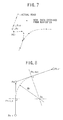
- FIG.7 is an illustration showing examples of note data actually obtained from a navigator;
- FIG.8 is an illustration showing how to determine the radius of curvature of an emerging curve;
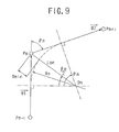
- FIG.9 is an illustration showing how to correct the obtained radius of curvature of the emerging curve;
- FIG.10 (a) to (d) are illustrations showing four cases at data reduction section;
- FIG.11 is a flow chart showing control of a vehicle movement control alterant.
-
- Referring to FIG.1, driving force, generated by an
engine 1 installed in front of a vehicle, is transmitted to a torque converter and an automatic gear train 2 located next to theengine 1, and transmitted further to a center differential 3 through a output shaft 2a .
The driving force is delivered to arear differential 7 through a rear drive shaft 4, apropeller shaft 5 and adrive pinion 6 in order and also delivered to a front differential 11 through atransfer drive gear 8, a transfer drivengear 9 and afront drive shaft 10 of which part forms drive pinion shaft.
The torque converter and automatic gear train 2, the center differential 3 and the front differential 11 and so on are integrally accommodated in acase 12. - The driving force inputted to the
rear differential 7 is transmitted to a left rear wheel 14rl through a left rear drive shaft 13rl and also transmitted to a right rear wheel 14rr through a right rear drive shaft 13rr.
The driving force inputted to the front differential 11 is transmitted to a left front wheel 14fl through a left front drive shaft 13fl and also transmitted to a right front wheel 14fr through a right front drive shaft 13fr. - The center differential 3 comprises the first and the second gear trains. A first sun gear 15 having a relatively large diameter engages with a plurality of
first pinions 16 having a relatively small diameter each , forming the first gear train. The first sun gear 15 is formed on the output shaft 2a transmitting the driving force into the center differential 3. A second sun gear 17 having a relatively small diameter engages with a plurality ofsecond pinions 18 having a relatively large diameter each, forming the second gear train.
The second sun gear 17 is formed on the rear drive shaft 4 transmitting the driving force to the rear wheels. - The
first pinion 16 and thesecond pinion 18 are formed on apinion member 19 in unit.
A plurality of thepinion members 19, e.g., 3(three), are rotatably supported by fixed shafts of acarrier 20. - The front end of the
carrier 20 is connected to thetransfer drive gear 8, transmitting the driving force to the front wheels. - Installed rotatably in the
carrier 20 from the front side is the output shaft 2a and installed rotatably from the back side is the rear drive shaft.
Thus thecarrier 20 accommodates the first sun gear 15 and the second sun gear 17 in its center part, the first sun gear and the second sun gear engaging with a plurality of the first and thesecond pinions pinion members 19 respectively. - Thus a compound type planetary gear without ring gear is formed. The first sun gear 15 (input) engaging the
first pinions 16 distributes driving force to one output through thesecond pinions 18 and the second sun gear 17 and to the other output through thepinion members 19 and thecarrier 20. - The center differential 3 of such a compound type planetary gear is capable of setting its torque distribution ratio with desirable value by appropriately setting intermeshing pitch circle diameters of the first and
second pinions - Two output members of the center differential 3, i.e., the
carrier 20 and the sun gear 17 are indirectly connected by atransfer clutch 21 which is a hydraulic multi-plate clutch with variable transfer capacity controlled by apower distribution controller 60. - The
transfer clutch 21 consists of a plurality of drivenplates 21a installed on the rear drive shaft 3 having the second sun gear 17 in unit and a plurality ofdrive plates 21b installed to thecarrier 20, while the drivenplates 21a and thedrive plates 21b are put alternately. Thetransfer clutch 21 is pressed or released by a piston (not shown) and a pressure plate (not shown) which are installed on thecase 12 and operated by hydraulic pressure in a hydraulic pressure chamber (not shown) hydraulically connected to a hydraulic device (not shown) controlled by thepower distribution controller 60. - In the case that the transfer clutch is open, the driving force is distributed in the specified ratio as it is set by the center differential 3. In the case that the transfer clutch is completely engaged, the differential function becomes inoperative, i.e., directly coupled so that the specified distribution ratio is canceled.
- Pressing force, i.e., transfer torque applied to the transfer clutch, is controlled by the
power distribution controller 60 so that the torque distribution ratio can vary from the ratio specified by the center differential, e.g., front 35/ rear 65 to the ratio when directly coupled, e.g.,front 50/rear 50. Thus torque distribution control, i.e. power distribution control, is established. - The
rear differential 7 has a same compound type planetary gear as the center differential 3 has. The driving force is transmitted to a differential case 31 through thedrive pinion 6 and acrown gear 32 provided on a periphery of the differential case 31 supported rotatably. - The differential case 31 accommodates a
carrier 34 supported rotatably, which is made cylindrical so that left side thereof forms a clutch drum 33a. Inserted into thecarrier 34 and coupled thereto is the right rear drive shaft 13rr. - A first sun gear 35 having relatively large diameter is provided in the differential case 31 and coupled thereto, engaging with a plurality of
first pinions 36 having a relatively small diameter each, forming the first gear train. - Further provided in the differential case 31 is a
second sun gear 37 having a relatively small diameter and formed on the end of the left rear drive shaft 13rl inserted into the differential case 31. Thesecond sun gear 37 engages a plurality ofsecond pinions 38 having a relatively large diameter each, forming the second gear train.
Thefirst pinions 36 and thesecond pinions 38 are formed onpinion members 39 in unit. A plurality of thepinion members 39, e.g., 3(three), are supported rotatably by fixed shafts of acarrier 34. - The compound type planetary gear has a differential function by appropriately setting tooth numbers of the first sun gear 35, the
second sun gear 37 and a plurality of the first andsecond pinions second sun gear 37. - The compound type planetary gear functions even torque distribution of left 50/right 50 as a specified torque distribution by appropriately setting intermeshing pitch circle diameters of the first and second sun gears 35 and 38 and the first and
second pinions - Further, the compound type planetary gear has a differential limiter function in itself by creating a differential limiting torque in proportion to strength of input torque due to to kinds of friction force between the
pinion members 39 and thecarrier 34.
One is friction torque occurs at edges ofpinion members 39 due to residual thrust force which is a result of counter balancing of respective thrust forces occurred on the first gear train and the second gear train by making the first sun gear 35/pinions 36 and second sun gears 35/pinions 38 in such configurations that the gears generate opposite and different thrust forces, for example helical gears with different helix angles for the first gear train and the second gear train respectively.
The other is friction torque occurs at the axis hole ofpinion members 39 due to pressing force against the fixed shaft of thecarrier 34 by composite force of repulsive and tangential forces caused by engagements of the first and second sun gears 35 and 37 and the first andsecond pinions - A
clutch hub 33b is provided on the left rear drive shaft 13rl at a part thereof positionally corresponding to the clutch drum 33a of thecarrier 34. A plurality of drive plates and a plurality of driven plates are installed onto the clutch drum 33a and theclutch hub 33b respectively and put alternately in order, forming a hydraulicmulti-plate clutch 33. - The
transfer clutch 33 is pressed or released by a piston (not shown) and a pressure plate (not shown) operated by hydraulic pressure in a hydraulic pressure chamber (not shown) hydraulically connected to a hydraulic device (not shown) controlled by the left/right wheeldifferential limiter controller 70. - The
rear differential 7 comprises a compound-type-planetary-gear-limited-slip-differential which distributes the driving force introduced by thedrive pinion 6 to the left rear drive shaft 13rf through thecrown gear 32, the differential case 31, the first sun gear 35 and thesecond sun gear 37, and to the right rear drive shaft 13rr through thecarrier 34, further comprising the hydraulic multi-plate clutch 33 which gives variably controlled friction force between one output, i.e., the left rear drive shaft and the other output, i.e., thecarrier 34.
An optimum differential limiting torque is obtained by combination of the differential limiting torque created in the compound-type-planetary-gear-limited-slip-differential in proportion and the additional differential limiting torque created by the hydraulic multi-plate clutch as necessary. - Accordingly, when the hydraulic multi-plate clutch is released by the left/right wheel
differential limiter controller 70, differential function is carried out smoothly with specified torque distribution, i.e., left 50/right 50, and when the hydraulic multi-plate clutch is engaged, differential between left and right wheels is limited and wheel slip is prevented, resulting in rather stabilized running characteristic. - A
brake actuator 40 is hydraulically connected to amaster cylinder 42 connected to abrake pedal 41 which is operated by a driver. When the driver operates thebrake pedal 41, themaster cylinder 42 pressurizes brake fluid and thebrake actuator 40 delivers brake pressure to each of 4 wheel cylinders, i.e., a front left wheel cylinder 43fl, a front right wheel cylinder 43fr, a rear left wheel cylinder 43rl and a rear right wheel cylinder 43rr of 4 wheels 14fl, 14fr, 14rl and 14rr through thebrake actuator 40 so that braking forces are applied to the 4 wheels. - The
brake actuator 40, a hydraulic unit comprising a pressurizing device, a reducing valve and intensifier, can apply brake pressure to the wheel cylinders 43fl,-43fr, 43rl and 43rr respectively, independently and controllably corresponding to input signals. - The wheels 14fl, 14fr, 14rl and 14rr provide a front left wheel speed sensor 44fl, a front right wheel speed sensor 44fr, a rear left wheel speed sensor 44rl and a rear right wheel speed sensor 44rr respectively so that each wheel speed is determined. The wheel speed signals are inputted to the
power distribution controller 60, the left/right wheeldifferential limiter controller 70 and the brake controller which are vehicle movement control means. - A
throttle opening sensor 45, agear position sensor 46, asteering wheel sensor 47, ayaw rate sensor 48, alateral acceleration sensor 49 and alongitudinal acceleration sensor 50 are provided and send signals respectively. Signals from thethrottle opening sensor 45 and the gear position sensor are inputted to thepower distribution controller 60 and the left/right wheeldifferential limiter controller 70, signals from thesteering wheel sensor 47 are inputted to the left/right wheeldifferential limiter controller 70 and thebrake controller 80, signals from theyaw rate sensor 48 and thelateral acceleration sensor 49 are inputted to the brake controller and the signals from the longitudinal acceleration sensor are inputted to the left/right wheel differential limiter controller. - The
power distribution controller 60 controls thetransfer clutch 21. Application of differential limiting force to the center differential 3 is basically controlled referring to a table map of predetermined duty ratios determined by variables of throttle opening th and vehicle speed V in different control modes, i.e., a normal control mode, a starting control mode, a steering control mode, a slip control mode or the like. - In the normal control mode, five kinds of the table maps mentioned above are prepared as the normal control references corresponding to the 1st through 4th and reverse gears , which represent a characteristic to make the differential limiting torque the lower, the smaller the throttle opening is and the higher the vehicle speed rises.
Accordingly, the differential limiting torque is controlled so as to improve turning performance and fuel economy. - In the starting control mode, the differential limiting torque is controlled in proportion to the throttle opening th when the vehicle speed is 0 km/h and steering is straight on, in order to ensure easy and smooth starting on a low friction road.
- In the steering mode control, the differential limiting torque is reduced from specified for the normal control mode depending on rotational ratio (NR/NF) of front and rear wheels in a specified vehicle speed range, in order to improve feeling of steering low speed range. NR is number of rear wheel rotation and NF is number of front wheel rotation.
- In the slip control mode, the differential limiting torque is controlled in a higher level than specified for the normal control mode when the rear wheel or the front wheel slips more than specified, in order to secure the maximum driving force and increase running stability.
- The
power distribution controller 60 receives control signals from a vehicle movement control alterant 100 (to be mentioned later) so that the increasing/reducing control of the differential limiting force to the center differential 3 is carried out by control signals from the vehiclemovement control alterant 100. - The left/right wheel
differential limiter control 70 controls the hydraulicmulti-plate clutch 33. Rotational speed difference of the 2 rear wheels is calculated from number of rotations of rear left and right wheels. In the case that the rear wheel rotation speed difference is bigger than a predetermined value, it is judged that the rear wheels are in slipping. In the case that the rear wheel rotation speed difference is smaller than a predetermined value, it is judged that the rear wheels are not in slipping. - Tn case of slipping, the hydraulic multi-plate clutch is controlled with a corrective pressure, referring to a predetermined map established by experiments and theoretical calculations according to the steering wheel angle f.
- In case of non-slipping, the hydraulic multi-plate clutch is controlled with a corrective pressure for non-slipping condition. The corrective pressure for non-slipping condition is determined referring a map according to variables of vehicle speed ,e.g., an average of the 4 wheel speeds, and throttle opening th. The pressure is also corrected when the gear position i is lower than specified and is further corrected by a longitudinal acceleration.
The map predetermined by experiments and theoretical calculations represents the characteristic that the pressure becomes higher in high speed and high load area. - When the hydraulic controls are carried out in the condition of slipping on non-slipping after judgement of the left/right wheel
differential limiter controller 70 , the hydraulic device (not shown) works and activates the hydraulicmulti-plate clutch 33. - The left/right
wheel limiter controller 70 receives control signals from the vehiclemovement control alterant 100 so that the control of the hydraulic multi-plate clutch 33 is carried out by instructions from the vehiclemovement control alterant 100. - The
brake controller 80 , e.g., a brake controller disclosed per Japanese Patent Laid-open No. 76894/1997 by this applicant, controls application of braking force to a selected wheel according to vehicle running conditions. - Referring to FIG. 2, the brake controller comprises a
vehicle speed calculator 81, asteering angle calculator 82, an aimed yaw rateregular gain calculator 83, an aimedyaw rate calculator 84, a predicted yaw rateregular gain calculator 85, a predictedyaw rate calculator 86, an aimed yawrate differential operator 87, a predicted yawrate differential operator 88, yaw ratedifferential deflection calculator 89, a first aimedbraking force calculator 90, a yawrate deflection calculator 91, a second aimed brakingforce calculator 92, a final aimed brakingforce calculator 93, abraking wheel discriminator 94, an output judgment 95 and abraking signal output 96. - The vehicle speed calculator receives wheel speed signals from the wheel speed sensors 44fl, 44fr, 44rl and 44rr, determines the vehicle speed V by calculation with a given formula, for example calculating an average of for wheel speeds obtained from the wheel speed sensors 44fl, 44fr, 44rl and 44rr, and sends signal of the vehicle speed V to the aimed yaw rate
regular gain calculator 83, the predicted yaw rateregular gain calculator 85 and the second aimed brakingforce calculator 92. - The steering angle calculator receives a signal from the
steering wheel sensor 47, calculates a real steering angle δ f by dividing the steering wheel angle f by the steering gear ratio N ( δ f= f/N), and send signal of the real steering angle δ f to the aimedyaw rate calculator 84, predictedyaw rate calculator 84 and the second aimed brakingforce calculator 92. - The aimed yaw rate
regular gain calculator 83 determines a yaw rate value, i.e., aimed yaw rate regular gain Gγ δ f(0), corresponding to the real steering angle δ f at turning along a constant circle by a predetermined formula, and send the calculated aimed yaw rate regular gain Gγ δ f(0) to the aimedyaw rate calculator 84 and the second aimed brakingforce calculator 92. The aimed yaw rate regular gain Gγ δ f(0) is determined by the following formula; - The aimed
yaw rate calculator 84 calculates an aimed yaw rate γ' based on the real steering angle δ f received from thesteering angle calculator 82 and the aimed yaw rate regular gain Gγ δ f(0) received from the aimed yaw rateregular gain calculator 83, counting response delay of the vehicle movement, and sends signal of the aimed yaw rate γ' to the aimed yawrate differential operator 87 and to the yawrate deflection calculator 91. - The aimed yaw rate γ' is calculated by the following formula;
- The predicted yaw rate
regular gain calculator 85 determines a predicted yaw rate regular gain Gγ δ f(0)LOW which is a predicted yaw rate value when the vehicle turns along a constant circle with a real steering angle δ f on a low friction road surface. The calculated predicted yaw rate regular gain Gγ δ f(0) LOW is sent to the predictedyaw rate calculator 86. The predicted yaw rate regular gain Gγ δ f(0)LOW is given by the following formula; - The predicted
yaw rate calculator 86 calculates a predicted yaw rate at low friction road γ'LOW based on the real steering angle δ f received from thesteering angle calculator 82 and the predicted yaw rate regular gain Gγ δ f(0)LOW received from the predicted yaw rate regular gain calculator85, counting response delay of the vehicle movement, and sends signal of the predicted yaw rate γ'LOW to the predicted yawrate differential operator 88.
The predicted yaw rate at low friction road γ'LOW is determined by the following formula;
The above formula (7) includes response delay of the vehicle movement expressed by 1st approximation, which is given in 2nd order otherwise. And the time constant TLOW is determined, for example by the following formula; - The aimed yaw
rate differential operator 87 calculates an aimed yaw rate differential S γ' which is a differential value of the aimed yaw rate γ' determined by the aimedyaw rate calculator 84 and the predicted yawrate differential operator 88 calculates a predicted yaw rate differential S γ'LOW which is a differential value of the predicted yaw rate γ'LOW determined by the predictedyaw rate calculator 86. - The aimed yaw rate differential S γ' calculated by the aimed yaw
rate differential operator 87 and the predicted yaw rate differential S γ'LOW calculated by the predicted yawrate differential operator 88 are sent to the yaw ratedifferential deflection calculator 89. And the yaw ratedifferential deflection calculator 89 calculates a yaw rate differential deflection d Δγ which is a deflection of the aimed yaw rate differential S γ' and the predicted yaw rate differential S γ'LOW. - The first aimed
braking force calculator 90 receives the yaw rate differential deflection dΔγ from the yaw ratedifferential deflection calculator 89 and calculates aimed braking forces for the front and rear wheels, i.e., a first front wheel aimed pressure BF1f and a first rear wheel aimed pressure BF1r. The calculated results of the first front wheel aimed pressure BF1f and the first rear wheel aimed pressure BF1 r are sent to the final aimed brakingforce calculator 93. The first front wheel aimed pressure BF1f and the first rear wheel aimed pressure BF1r are determined by the following formula;
In the formula (10), G1 is the first large gain and dΔγ × Iz/ (df/2) is a part showing the first theoretical braking force for the front wheels. In the formula (11), G1×G2 is the first small gain and dΔγ×Iz/ (dr/2) is a part showing the first theoretical braking force for the rear wheels. In order to prevent loosing stability caused by side slips occurring on rear wheel or to prevent feeling of unstableness given by unexpectedly strong turning moment occurring when the rear wheels are braked, especially on low friction road, the first rear wheel aimed pressure BF1r is made so smaller by multiplying the first theoretical braking force for the rear wheels with the first small gain. - As described above, the first aimed pressures BF1f and BF1r derived based on the yaw rate differential deflection dΔγ are values which are calculated supposing that the vehicle runs on a low friction road. The reason why supposing low friction road running is the more brake controlling is needed, the lower road friction is. The respective specified values applicable on low friction road have been determined from data obtained by experiments using vehicle models or by well known theoretical calculations.
- The yaw
rate deflection calculator 91 determines a yaw rate deflection Δγ (=γ-γ') , subtracting the aimed yaw rate γ' calculated by the aimedyaw rate calculator 84 from a real yaw rate γ detected by theyaw rate sensor 48. The yaw rate deflection Δγ is sent to the second aimed brakingforce calculator 92, thebraking wheel discriminator 94. - The second aimed braking
force calculator 92 calculates aimed braking forces for the front and rear wheels, i.e., a second front wheel aimed pressure BF2f and a second rear wheel aimed pressureB F 2r. The second aimed pressures BF2f and BF2r calculated are sent to the final aimed brakingforce calculator 93.
The second aimed pressures BF 2f and BF 2r are determined by the following formula; - In the above formula (14), Δγ may be further corrected considering a side slip angle α which is made by vehicle proceeding direction and vehicle longitudinal axis. To be more concrete, a side
slip angle calculator 97 indicated with broken lines in FIG.2 determines the side slip angle α and the second aimed brakingforce calculator 92 calculates a yaw rate deflection correcting value Δγ' corresponding to the side slip angle α, then Δγ + Δγ' is put in lieu of Δγ in the formula (14), i.e., - The side
slip angle calculator 97 determines the side slip angle α by ,for example, such calculation that a side slip angle differential dβ is obtained based on a lateral acceleration Gy, the vehicle speed V and the yaw rate γ and then the side slip angle differential dβ is integrated (Integral:β). - The yaw rate deflection correcting value Δγ' corresponding to the side slip angle α is given as shown on FIG.5, wherein an insensitive band for example, is provided where the yaw rate deflection correcting value Δγ'equal to 0 in a band the side slip angle α varies from -1 to +1.
- And the second aimed braking
force calculator 92 so arranged to receive signals from the vehiclemovement control alterant 100 that the brake controlling characteristic is alterable to become sensitive according to a control instruction from the vehicle movement control alterant 100 to make the insensitive and of the side slip angle α narrow. - The above mentioned G3 and G4 are gains which are set with same reason as G1 and G2 previously mentioned. In the formula (12), G3 the second large gain and the other part represents the second theoretical braking force for the front wheels. In the formula (13), G3×G4 is the second small gain and the other represents the second theoretical braking force for the rear wheels. Accordingly strength of barking forces to the rear wheels are also repressed by the formulas (12) and (13). Repression of braking forces applied to rear wheels is done finely by setting respective gains of G1 through G4 so that a driver does not feel unusual vehicle movement and running stability is upgraded.
- The final aimed braking force calculator determines final aimed braking forces ( ,i.e., final aimed pressures, BFf and BFr) by adding the first aimed pressures BF1f, BF1r and the second aimed pressures BF2f, BF2r respectively. The calculated final aimed pressures BFf and BFr are sent to the
braking signal output 96. - The
braking wheel discriminator 94 selects which wheels are to be applied with braking from combinations of signs of the real yaw rate γ and the yaw rate deflection Δγ. The following combinations are provided.
Signs of the real yaw rate γ and the aimed yaw rate γ' are given in the condition, i.e. (+)plus in a direction of left turning and (-)minus in a direction of right turning.
In order to judge straight running situation, ε ,a small and plus figure close to 0, predetermined by experiments or calculation is employed.
And, in order to judge that the vehicle is in almost neutral steering condition against the aimed yaw rate γ', ε Δγ , a small and plus figure close to 0, predetermined by experiments or calculation is employed.
Referring to FIG.6 - (Case 1) γ > ε , Δγ < - ε Δγ Means under steering against aimed yaw rate γ' in left tuning. ------braking rear left wheel
- (Case 2) γ > ε , Δγ > ε Δγ Means over steering against aimed yaw rate γ' in left tuning. -----braking front right wheel
- (Case 3) γ < ε , Δγ <- ε Δγ Means over steering against aimed yaw rate γ' in right tuning. -----braking front left wheel
- (Case 4) γ < ε, Δγ > ε Δγ Means under steering against aimed yaw rate γ' in right tuning. -----braking rear right wheel
- (Case 5) When the judgment is| γ | < | ε | , i.e., approximately straight or | Δγ | = | ε Δγ | ,i.e., approximately neutral steering against aimed yaw rate γ', no selection and no braking application are done.
-
- Except the cases of the approximately straight running condition determined by γ | < | ε | and approximately neutral steering condition against aimed yaw rate γ' determined by | Δγ | = | ε Δγ | , when signs of the real yaw rate γ and the yaw rate deflection Δγ are different, rear inside wheel is selected as braking wheel, and when signs of the real yaw rate γ and the yaw rate deflection Δγ are the same, front outside wheel is selected as braking wheel. A result of the judgment of the
braking wheel discriminator 94 is sent to thebraking signal output 96. - The output judgement 95 judges whether the yaw rate deflection Δγ is within a control range or not and sends a result to the
braking signal output 96. A judgment threshold ε Δ, which is insensitive band of control, is provided as mentioned later so that the output judgement 95 compares the judgment threshold ε Δ and the yaw rate deflection Δγ and judges whether the yaw rate deflection Δγ is within a control range or not. - The first threshold ε ΔM is used for the judgment threshold ε Δ ordinarily, and the second threshold ε ΔS supersedes it starting from the time when the vehicle movement characteristic changes from under steering to over steering till when a predetermined period ends or till when either yaw rate deflection or real yaw rate becomes nearly 0. The first threshold ε ΔM and the second threshold ε ΔS are positive values predetermined based on experiments or calculations and size relation of these thresholds used for judgment on the yaw rate deflection Δγ is as follows;
- Setting At least one of The first threshold ε ΔM and the second threshold ε ΔS variable, it is possible to provide the judgment threshold ε Δ with more appropriate value corresponding to vehicle speed It is reasonable to make non control area larger at low speed, because corrective operation by a driver is so effective that control is not required when a vehicle movement becomes unstable at low speed, comparing to the vehicle movement at high speed.
- The output judgement 95 receives signals from the vehicle
movement control alterant 100. Threshold is set smaller in the output judgement 95 according to an instruction from the vehiclemovement control alterant 100 so that control sensitivity is changeable towards a direction where braking control is carried out promptly. - According to the signal from the
output judgement 100 ,thebraking signal output 96 arranges that thebrake actuator 40 applies the final front wheel aimed pressure BFf or the final rear wheel aimed pressure BFr calculated by the final aimed brakingforce calculator 93 to a braking wheel selected by thebraking wheel discriminator 94. - Referring to FIG.3, the vehicle is equipped with a
navigator 110, which is a running position locating means for determining location of the running vehicle, aroad geometry detector 130 and acurve geometry calculator 120, which are curve data creating means for acquiring curve data while detecting vehicle position and a curve in front of the vehicle. - In general, as shown in FIG.3, the
navigator 110 consists mainly of a vehicleposition detection sensor 110a, anauxiliary memory 110b, adisplay 110c, acontrol section 110d, and a processing unit 8e. - The vehicle
position detection sensor 110a gathers running information related to vehicle position. Thesensor 110a consists manly of a GPS (Global Positioning System) receiver to receive positioning signals from GPS satellites so as to determine the position of the vehicle; a magnetic sensor to detect the absolute running direction of the vehicle; and a wheel speed sensor composed of an electromagnetic pickup facing an outer periphery of a rotor fixed to the wheel to output a pulse signal when it crosses projections on the outer periphery of the rotor. - The
auxiliary memory 110b is a CD-ROM device, containing a CD-ROM in which road information is stored, topographical information and other road map information. In the CD-ROM, road map information is stored at several hierarchical levels in varying scales as well as road type information such as motor ways, ordinary national roads and local roads, and information on passage conditions of intersections. As shown in-FIG.7, the road data included in the road map information consist of point data (nodes) entered at given intervals of space and line data(link) formed by connecting these nodes. - The
displays 110c is a liquid crystal display which displays maps, the vehicle position (the latitude, longitude and altitude),orientation, the position of vehicle on the map, and the optimum routing up to the destination.
A touch panel as thecontrol section 110d is integrated in thedisplay 110c (liquid crystal display), making it possible to change displaying of the map scale, detailed display of place names, and displays of area information and route guidance. - The
processing unit 110e combines the vehicle running information obtained from the vehicleposition detection sensor 110a and the map information read from theauxiliary memory 110b, while making map matching and other processing. The results are fed to thedisplay 110c based on an operating signal sent from thecontrol section 110d,so as to display the present position or the vehicle, its peripheral map, the optimum route to the destination and other information. The node data of the road and the information on road types are sent to the vehiclemovement control alterant 100 and thecurve geometry detector 120 as required. - According to this embodiment, an important function of the
road geometry detector 130 is to detect road width. Thedetector 130 consists mainly of a pair ofCCD Cameras 130a,animage processor 130b and aroad width detector 130c. - The pair of
CCD cameras 130a are installed apart with a fixed distance at the right and left sides of the front part of the ceiling in the compartment, so as to make stereoimages of the objects outside of the vehicle. Signals of the images taken by theCCD cameras 130a are sent to theimage processor 130b. - A pair of stereoimages taken by the
CCD cameras 130a are fed to theimage processor 130b that determines distance data over the entire image field by way of trigonometric calculations according to the deflections of the positions of objects in respective each images, so as to generate a 3D-image showing distances. The generated 3D-image is sent to theroad width detector 130c. - The
road width detector 130c firstly recognizes the road being traveled on by carrying out a histogram processing of the distance distributions or the 3D-images sent from theimage processor 130b. The road width thus calculated is then sent to thecurve geometry calculator 120 as required. - The road width detector 130C approximates, for example, lane-dividing lines as broken lines, and judges the area between the left and right broken lines as the traffic lane for the vehicle. The road width is calculated from the distance between the left and right broken lines of the traffic lane.
As theroad geometry detector 130 detects road geometry to determine the road width, it is possible to obtain more accurate data about positioning of the vehicle by comparing the road geometry detected by theroad geometry detector 130 with the road geometry data on the map in thenavigator 100, and correcting the vehicle position on the map. - As shown in, e.g., FIG.3, the
curve geometry calculator 130 comprises a three-node detector 120a, a Pn-1Pn distance calculator 120b, a Pn Pn+1distance calculator 120c, a long/short judgment section 120d, amid-point calculator 120e, a mid-point-same-distance point calculator 120f, aradius calculator 120g and acorrector 120h. - As shown in FIG.7, the three-
node detection detector 120a reads three nodes located at given intervals in the traveling direction of the vehicle or on the road selected by the driver, successively (from a node closer to the vehicle) as the first node Pn-1, the second node Pn and the third node Pn+1, from the road nodes inputted from thenavigator 110. Among these read three nodes, the positional information or the first and second nodes Pn-1 and Pn are outputted to the Pn-IPn distance calculator 120b,and the positional information of the second and third nodes Pn and Pn+1 are outputted to the Pn Pn+1 distance calculator 24c. Pn-1,Pn,and Pn+1 are represented by (Xn-1,Yn-1), (Xn,Yn), and (Xn+1,Yn+1), respectively. The representative node of the curve is Pn. Therefore, the curve data at points P1, P2, ..., and Pn are calculated by the combination of (P0, P1, P2) (P1, P2, P3), ..., and(Pn-1, Pn, Pn+1), respectively.
The Pn-Pn distance Calculator 120b Calculates a straight distance connecting Pn-1 and Pn based on the positional information of Pn-1 and Pn input from the three-node detector 120a, so as to send the straight distance to the long/short judgment 120d and thecorrector section 120h. - The Pn Pn+1
distance calculator 120c calculates a straight distance connecting Pn and Pn+1 based on the positional information of Pn and Pn+1 inputted from the three-node detector 120a, and sends the straight distance to the long/short judgment 120d and thecorrector 120h. - The long/
short judgment 120d compares the straight distance connecting Pn-1 and Pn inputted from the Pn-1 Pn distance calculator 24b and the straight distance connecting Pn and Pn+1 inputted from the Pn Pn+1distance calculator 120c, so as to judge which is shorter. Every data (position, distance) for the shorter straight distance is output to themid-point calculator 120e and thecorrector 120h, while every data (position, distance) for the longer straight distance is outputted to the mid-point-same-distance point calculator 120f. - In this connection, when the comparison at the long/
short judgment 120d shows an equal length for the both straight distances, that is, when either one can be used, it is previously set so that the straight line connecting Pn-1 and Pn is to be handled as the shorter Straight line (or it may be previously set so that the straight line connecting Pn and Pn+1 is to be handled as the shorter straight line). - Based on the every data (position, distance) for the shorter straight line inputted from the long/
short judgment 120d, themid-point calculator 120e not only calculates half of the shorter straight distance, but also determines the mid point position on the shorter straight line.
Here, when the shorter straight line is the straight line connecting Pn-1 and Pn, and when the mid-node Pn-1,n is represented as (Xn-1,n , Yn-1,n)mid-point calculator 120e is outputted to the mid-point-same-distance point calculator 120f and theradius calculator 120g. - Based on the data(position, distance)of the longer straight line inputted from the long/
short judgment 120d and the data(half the distance)of the shorter straight line inputted from the mid-point calculator 24e, the mid-point-same-distance point calculator 120f determines a mid-point-same-distance point at the position at half the distance of the Shorter straight line apart from Pn on the longer straight line. Here, let us assume that the longer straight line is the line connecting Pn and Pn+1, and let us represent the mid-point-same-distance point by Pn,n+1 (Xn,n+1 , Yn,n+1). Then,distance point calculator 120f is outputted to theradius calculator 120g. - As shown in FIG.8, based on the positional data of a mid-node Pn-1,n inputted from the
mid point calculator 120e and the positional data of a mid-point-same-distance node Pn,n+1 calculated by the mid-point-same-distance point calculator 120f, theradius calculator 120g determines as the central position "On" of the emerging curve on the road the position of the crossing point of a line that crosses the shorter straight line (here, Pn-1 Pn) at right angle with each other at the mid-node Pn-1,n and a line that crosses the longer straight line (here,PnPn+1) at right angle with each other at the mid-point-same-distance node Pn,n+ 1. Then, based on the determined central position "On", theradius calculator 120g calculates the radius of curvature Rn of the Curve. The calculation results are outputted to the corrector 120h. in other words: Therefore,
Xn+ 1·Yn-1 - Xn-1·Yn + Xn·Yn-1 - Xn·Yn+1+Xn+ 1·Yn)Therefore, the radius of curvature Rn is obtained from the following expression(23) :
- The distance Lon from the center of the curve 0n to the representative node of the curve ,i.e., the second node Pn is obtained from the following expression (24):
corrector 120h calculates the difference Deln between the radius of curvature Rn obtained by theradius calculator 120g and the distance Lon from the curve center position On to the second node Pn. When the difference Deln exceeds a given error value (to be described later), thecorrector 120h corrects the radius of curvature Rn so that the difference Deln be within the given error value. - Final curve information for each node, which has been corrected by the
corrector 120h or left intact because of the difference Deln being smaller than the given error set value, are outputted to thedata reducti 120i for storage and subsequent processing. Here, the final curve information for each node includes the position(Xn,Yn) of the representative node Pn of a curve; the distance Ln between node Pn-1 and node Pn; final radius of Curvature Rn; curve angles n obtained from the angle formed by lines Pn-1 Pn and Pn Pn+1; the distance between the curve starting point Lsn (the intersection point of the line Pn-1 Pn and the perpendicular from the curve center On to the line Pn-1 Pn) and the Pn-1; and the distance Lssn from vehicle position to each representative node of the curve - The error Set value depends on road Width D and the shorter line distance judged by the long/
short judgment 120d, thereby being represented as α·D.(Here, α is a constant to be set in accordance with the shorter line distance, hereinafter referred to as a node interval correction factor.) - Normally, a road width obtained from the
road geometry detector 130 is to be adopted or the foregoing road width D, but, when theroad geometry detector 130 cannot tell any road width, the foregoing road width D may be set based on the road type information to be obtained from thenavigator 110. In this connection, the wider the road width D, the larger the error set value, thus going toward no correction. This means that, the wider the actual road width, the larger the radius of the curvature Rn. - The fact that the interval or nodes is short means that the road is accurately defined by nodes on the map. in that case, corrections of the difference Deln is not significant.
- Therefore, as with the node interval correction factor α, the shorter line distance, the larger the node interval correction factor α, thus increasing the error set value to eliminate the chance for correction. For example, when the shorter line distance is shorter than 20 m, α=1.2, and when the shorter line distance is shorter than 100 m, α is taken as 0.6, and when the shorter line distance is longer than 100 m, α is 6, and when the shorter line distance is longer than 100 m, α is taken as 0.3.
- FIG.4 shows a detailed correction to be made by the
corrector 120h. The vector from Pn-1 to Pn is denoted as Blve (ve meaning a vector),and the vector from P2 to P3 is denoted as B2ve.Therefore, the difference Deln is as follows: In this connection, when the difference Deln is larger than the error set value(α·D),correction is made so that Deln equals αh·D for the radius of curvature Rn.
In detail,

- As described, since curve information is obtained from the
curve geometry calculator 120, the irregular nodes from thenavigator 110 can be used as it is, thus resulting in simple calculation without data supplement or complex calculations, so that the radius of curvature of a road being traveled on can be determined quickly/ and accurately. - Further, in this case, since the continuity of respective curve detection nodes for determining the radius of curvature is natural or smooth, data accurately representing an actual load geometry can be obtained.
- Furthermore, even if possible calculation errors appeal, the calculated radius of curvature always becomes smaller than the actual radius of curvature, thereby preferable when setting off a proper warning in the warning/detection control when approaching a curve.
- Provision of the
corrector 120h for the radius of curvature can help an accurate calculation of the radius of curvature. Furthermore, the error set value which a variable in accordance with the actual road geometry and the number of nodes can make calculations more accurate. In other words, since the wider road actually represents the larger radius of curvature, the wider the road width, the larger the error set value, thus eliminating the need or chance for correction. Furthermore, a shorter straight line distance results in fine setting of nodes, thus probably representing the road more accurately, so that the shorter the shorter line distance, the larger the error set value, thereby the more eliminating the chance for correction. - The
data reduction 120i is provided to reduce data corrected by thecorrector 120h for every node, eliminating unnecessary calculations. - The
data reduction 120i assumes the following four cases to reduce the voluminous curve information only to really needed ones.
CASE I --- Sharp curve, but there is a marginal deceleration distance (= Rn-1 -Rn) before reaching node Pn from node Pn-1(FIG.10(a))
If |Rn-1| 〉 |Rn| , Rn-1·Rn > 0 and Ln 〉 | Rn-1|-|Rn|
then the curve information for the nodes Pn-1 and Pn is each necessary. Because there is a marginal distance for deceleration before the vehicle reaches node Pn from node Pn-1, independent control may be necessary for both nodes. - Considering that node Pn-1 and node Pn both represent the same curve, a total curve angle sn at node Pn is considered to be equal to the sun of a total curve angle S(n-1) at node Pn-1 and 2cos-1(Rn/Lon). Therefore, the total curve angle sn at node Pn =
the total curve angle s(n-1) at node Pn-1 + 2cos-1(Rn/Lon).
CASE 2 --- A Sharp Curve, and there is no marginal deceleration distance(= Rn-1 - Rn )before reaching node Pn from node Pn-1. (FIG.10(b))
If |Rn-1|〉|Rn| , Rn-1·Rn〉0 and Ln〈 |Rn-1|-|Rn|,
then the curve information of node Pn-1 can be neglected. in other words, the execution of control for node Pn curve can absorb the execution of control for node Pn-1 curve, thus making the curve information of node Pn-1 useless (negligible) so that the total number of control executions to be made can be minimized. - Considering that node Pn-1 and node Pn both represent the same curve, a total curve angle sn at node Pn is considered to be equal to the sum or a total curve angle S(n-1) at node Pn-1 and 2cos-1(Rn/Lon). Therefore, the total curve angle
sn at node Pn =
the total Curve angle S(n-1) at node Pn-1 + 2 cos-1(Rn/Lon).
CASE 3 --- Mild curve(FIG.10(c))
If |Rn-1|〈|Rn| , Rn-1·Rn〉0 ,
then the curve information of node Pn can be neglected. In other words, since the vehicle is sufficiently decelerated by the node Pn-1, the curve information of the node Pn which represents a milder curve than that of the node Pn-1 is useless, thus being neglected. In this connection, in the case of long Ln, full acceleration (if node Pn-1 and node Pn both can be regarded as independent curves) may boost the vehicle speed a great deal before the vehicle reaches node Pn, so that the curve information for node Pn may be maintained depending on the magnitude of Ln. - Considering that node Pn-1 and node Pn both represent the same curve, a total curve angle sn at node Pn is considered to be equal to the sum of a total curve angle S(n-1) at node Pn-1 and 2cos-1(Rn/Lon). Therefore, the total curve angle
sn at node Pn =
the total curve angle s(n-1) at node Pn-1 + 2cos-1(Rn/Lon). - In this connection, if the curves at node Pn-1 and node Pn are regarded as independent from each other, the curve angle n at the node Pn is not added, but a new addition calculation will be started (depending on the magnitude of Ln).
CASE 4 --- The turning directions of curves are changed from right to left or from left to right(FIG.10(d)).
If Rn-1·Rn<0,
then, the curve information for node Pn is needed since turning direction is considered to be different when the vehicle runs from node Pn-1 to node Pn. - The addition result of curve angles which continued up to node Pn-1 is defined as the total curve angle s(n-1) up to node Pn-1.
- Furthermore, ode Pn can be a star point to calculate a total curve angle sn independent from the total curve-angle s(n-1).
- The total curve angle sn at node Pn = 2cos-1(Rn/Lon)
- In this calculation, the reason why the deceleration distance is defined as the difference between the radius of curvature Rn and the radius of curvature Rn-1 is as follows:
- Theoretically the deceleration distance is expressed as follows:where

- Vpn = reference allowable approaching speed at node Pn
- a = deceleration
- ayln = alowable latera acceleration
-
- When the deceleration a is assumed to be 1/2ayl,then
- Such data deduced by the
data deduction 120i are entered to the vehiclemovement control alterant 100 together with data before the deduction. - The vehicle
movement control alterant 100 is means to alter the characteristic of the vehicle movement controllers, receiving data from thenavigator 110 and thecurve geometry calculator 120 and altering controls of thepower distribution controller 60, the left/right wheeldifferential limiter controller 70 and thebrake controller 80 by sending signals torespective controllers - The following are explanations how they work:
- The power distribution controller receives respective wheel speed signals from the front left wheel speed sensor 44fl, the front right wheel speed sensor 44fr, the rear left wheel speed sensor 44rl and the rear right wheel seed sensor 44rr, a signal of throttle opening th from the
throttle opening sensor 45 and a signal of gear position from thegear position sensor 46, and then carry out control of differential limiting force to be applied to the center differential 3, i.e., controlling the transfer torque of the transfer clutch 21 in the normal control mode, the starting control mode, the steering control mode and the slip control mode, referring to the tabulated duty ratio map by throttle opening th and vehicle speed V based on running conditions.
Thus, for example, provided that specified torque distribution is front 35/rear 65, torque distribution varies according to the control form front 35/rear 65 tofront 50/rear 50 which is torque distribution at direct coupling of the transfer clutch. - The left/right wheel
differential limiter controller 70 receives respective wheel speed signals from the front left wheel speed sensor 44fl, the front right wheel speed sensor 44fr, the rear left wheel speed sensor 44rl and the rear right wheel seed sensor 44rr, a signal of throttle opening th from thethrottle opening sensor 45, a signal of gear position from thegear position sensor 46, a signal of steering wheel angle f from thesteering wheel sensor 47 and a signal of longitudinal acceleration Gx from thelongitudinal acceleration sensor 50 and then carry out control of limiting differential of the rear left and right wheels by controlling the hydraulic multi-plate clutch 33 or therear differential 7 according to running conditions. - As mentioned before, slip conditions of the rear wheels are judged and if it is judged as slip, applied to the clutch is hydraulic pressure set for slip conditions based on the steering wheel angle f by referring to a data map predetermined by experiments and theoretical calculations.
- If it is judges as non-slip, applied to the clutch is hydraulic pressure set for non-slip conditions. The hydraulic pressure set for non-slip conditions is controlled based on the vehicle speed V, e.g., an average of 4 wheel speeds, and the throttle opening th by referring to a data map predetermined by experiments and theoretical calculations and characterized in having bigger values as the vehicle speed and load become higher, and is further controlled in corrective way by the longitudinal acceleration and information that the gear position is lower than specified.
- The
brake controller 80 receives respective wheel speed signals from the front left wheel speed sensor 44fl, the front right wheel speed sensor 44fr, the rear left wheel speed sensor 44rl and the rear right wheel seed sensor 44rr, a signal of steering wheel angle f from thesteering wheel sensor 47, a signal of real yaw rate γ from theyaw rate sensor 48, and signal of lateral acceleration Gy from the lateral acceleration sensor 49 (for the case of correction being done by the yaw rate deflection correcting value Δγ' corresponding to the side slip angle α) and then calculate the aimed barking force BFf and BFr correcting over steering or under steering characteristic of the vehicle based on the following values calculated thereby; - Sγ': differential of the aimed yaw rate γ'
- Sγ'Low: differential of the aimed yaw rate at low friction road γ'Low
- dΔγ: deflection of Sγ' and Sγ' Low
- Δγ: deflection of the real yaw rate γ and the aimed yaw rate γ' These aimed braking force may be corrected by using the yaw rate deflection correcting value Δγ' corresponding to the side slip angle α.
-
- The
brake controller 80 selects the rear inside wheel for correcting under steering characteristic while turning, or the front outside wheel correcting over steering characteristic while turning, and send control signal to the brake actuator 25 so that the aimed braking force is applied to the selected wheel. This is carried out ,while comparing the yaw rate deflection Δγ with the threshold εΔ, when the yaw rate deflection Δγ comes from inside of the insensitive band to the outside, i.e., control area. - The
navigator 100 combines vehicle running data and map data while operating map matching and sends its results to thedisplay 110c based on an operating signal for displaying the current position of the vehicle, the map showing the area, the optimum route to the destination and so on, and also sends its results to the vehiclemovement control alterant 100 and thecurve geometry calculator 120 as necessary. - The
road geometry detector 130 generates 3D-images showing distances, based on the images taken by the pair ofCCD cameras 130a, recognizes the road to be traveled by carring out a histogram processing about distance distributions of the 3D-images, calculates the road width, and then sends it to thecurve geometry calculator 120 as necessary. - The
curve geometry calculator 120 detects three nodes, i.e., the first node, second node and the third node, in the traveling direction from the vehicle on and judges short/ long, on the two straight lines, one staring from the first node and ending at the second node, the other from the second node to the third node. - Then a mid point is set on the short line by calculating the half distance of the short line and a mid-point-same-distance point is set on the long line in the half distance of the short line from the second node.
- Then other two straight lines are drawn so that one is passing through the mid point and crossing the short line at right angle and the other is passing through the mid-point-same-distance point and crossing the long line at right angle. The point these two lines are crossing each other is determined as center of the curve and a radius of the curve is calculated. Thus the curve data are obtained, further corrected based on the road width data from the
road geometry detector 130, reduced in a predetermined manner and sent to the vehiclemovement control alterant 100. - The vehicle movement control alterant 100 carries out controls according to the flow chart as shown in the FIG.11.
- At S101 (S means step.), position data and curve data on the road to be traveled are read from the
navigator 110 and thecurve geometry calculator 120 respectively. - At next S102, judgement is made if the vehicle is running in the curve or not. The curve data are compared with predetermined conditions, e.g., for road width, vehicle speed, radius of curvature. If the radius of curvature of the curve data is smaller than that of the predetermined conditions corresponding to the road width and vehicle speed, it is judged that the vehicle is running in a curve.
- In the case the vehicle is not in a curve, then S103 is taken, where it is judged if the distance to the curve entrance is less than Lcul, which is predeterminedly given according to variables of, for example, road width, vehicle speed and radius of curvature of curve to be traveled.
- In the case the distance is not less than Lcul, the program goes to an end.
- In the case the distance is less than Lcul, S104 is taken, where the following signals are sent to the related controllers respectively;
- a signal setting the insensitive band narrower to the
brake controller 80, - a signal setting differential limiting force lower (i.e.,
weakening pressure to be applied to the hydraulic
multi-plate clutch 33 of the rear differential 7) to the left/right wheeldifferential limiter controller 70 and - a signal reducing transfer torque (i.e., resuming torque
distribution by the center differential to the specified) to
the
power distribution controller 60.
Then the program goes to an end. -
- In the case it judged that the vehicle is in a curve at S102, S105 is taken, where it is judged if the distance to the curve end is less than Lcu2, which is predeterminedly given according to variables of, for example, road width, vehicle speed and radius of curvature of curve to be traveled.
- In the case the distance is not less than Lcu2, S104 is taken, where the following signals are sent to the related controllers respectively;
- a signal setting the insensitive band narrower to the
brake controller 80, - a signal setting differential limiting force smaller (i.e.,
weakening pressure to be applied to the hydraulic
multi-plate clutch 33 of the rear differential 7) to the left/right wheeldifferential limiter controller 70 and - a signal reducing transfer torque (i.e., resuming torque
distribution by the center differential to the specified) to
the
power distribution controller 60.
Then the program goes to an end. -
- In the case the distance is less than Lcu2 at S105, S106 is taken, where the following signals are sent to the related controllers respectively;
- a signal setting differential limiting force bigger (i.e.
strengthening pressure to be applied to the hydraulic
multi-plate clutch 33 of the rear differential 7) to the left/rightdifferential limiter controller 70 and - a signal increasing transfer torque (i.e., torque distribution
by the center differential becoming equal for front and rear)
to the
power distribution controller 60. -
- In other words, when the vehicle is not in the curve and the distance to the curve is less than predetermined Lcu1, the following controls are carried out, preparing for turn at the curve;
Thebrake controller 80 makes the insensitive band narrower, increasing sensitivity so that steering responsiveness is improved.
The left/rightdifferential limiter controller 70 reduces the differential limiting force so that turning performance of the vehicle becomes better.
Thepower distribution controller 60 reduces the transfer torque so that turning performance of the vehicle becomes better. - When the vehicle has reached the area within Lcu2 to the curve end, the following controls are carried out, preparing for stable transition from curved road to strait road without having abnormal feeling;
The left/rightdifferential limiter controller 70 increases the differential limiting force so that running stability is improved.
Thepower distribution controller 60 increases the transfer torque so that running stability is improved. - Thus, according to the preferred embodiment or the present invention, a curve to be traveled is detected beforehand and characteristics of the respective vehicle movement controllers are altered and activated so that driving through a curve including entering in and going out the curve can be done appropriately.
- Though the explanation or the preferred embodiment is done on the vehicle equipping three vehicle movement controllers, i.e., the power distribution controller, the left/right wheel differential limiter controller and the brake controller, this is applicable to a vehicle having at least one of the three controllers.
- Though the explanation of the left/right wheel differential limiter controller is done on the vehicle which equips it for rear wheels, it is applicable to a vehicle which equips the controller for front wheels.
- Though the explanation of the power distribution controller is done for the specification distributing more torque to rear wheels, it is applicable to a specification distributing more torque to front wheels.
- Though the explanation is done on the center differential and the rear differential which are both compound type planetary gear, it is applicable to those of a bevel gear type or a planetary gear type having a ring gear.
- Though the embodiment shows the case where, the characteristic the brake controller is changed by setting the insensitive band, i.e., threshold of yaw rate deflection, narrower, the similar effect can be obtained, for example as shown in FIG.5, by narrowly setting an insensitive band of side slip angle, in the case yaw rate deflection is corrected according to side slip.
- Controlling of the braking force by the brake controller may be other types than shown in the embodiment.
- Thus the vehicle dynamic control system, according to the present invention, alters characteristics of respective vehicle movement controllers, recognizing beforehand details of a curved road to be traveled, so that the controllers of the system can function properly for coming and foreseeable running conditions and current running conditions and driving through a curve can be done appropriately, including entering in and going out the curve.
- While the presently preferred embodiment of the present invention has been shown and described, it is to be understood that this disclosure is for the purpose of illustration and that various changes and modifications may be made without departing from the scope of the invention as set forth in the appended claims.
Claims (6)
- A vehicle control system comprising:a vehicle position detecting means for determining position of a running vehicle;a curve geometry detecting means for detecting an emerging curve and calculating curve geometry;at least one vehicle movement controlling means for controlling movement of said vehicle; anda vehicle movement control altering means for altering a characteristic of said vehicle movement controlling means to a characteristic favorable to turning along said emerging curve in accordance with said calculated curve geometry, said vehicle not running in the curve and positioning within a pre-determined distance to the curve.
- A vehicle control system according to claim 1,
wherein said vehicle movement control altering means alters a characteristic of said vehicle movement controlling means to a characteristic favorable to stabilizing vehicle posture , said vehicle running in the curve and positioning within a pre-determined distance to the curve end and to another characteristic favorable to turning, said vehicle running in the curve and positioning out of a pre-determined distance to the curve end. - A vehicle control system according to claim 1,
wherein said vehicle movement controlling means is at least one among a brake controller applying braking force to a wheel selected in a predetermined manner based on vehicle running conditions, a left/right wheel difference limitation controller controlling differential limiting force between left and right wheels and a power distributing controller controlling differential limiting force applied to a center differential device between front and rear wheels for distributing driving force to front and rear wheels based on the vehicle running conditions. - A vehicle control system according to claim 3,
wherein altering of a characteristic of said vehicle movement controlling means to a characteristic favorable to turning is done by changing control parameters, said vehicle movement controlling means being said brake controller - A vehicle control system according to claim 3,
wherein altering of a characteristic of said vehicle movement controlling means to a characteristic favorable to turning is done by reducing differential limiting force between said left and right wheels and altering to another characteristic favorable to stabilizing running is done by increasing differential limiting force between said left and right wheels, said vehicle movement controlling means being said left/rear wheel differential limitation controller - A vehicle control system according to claim 3,
wherein altering of a characteristic of said vehicle movement controlling means to a characteristic favorable to turning is done by setting differential limiting force for uneven torque distribution to said front and rear wheels and altering to another characteristic favorable to stabilizing running is done by setting differential limiting force for even torque distribution to said front and rear wheels, said vehicle movement controlling means being said power distributing controller controlling differential limiting force applied to a center differential device.
Applications Claiming Priority (3)
| Application Number | Priority Date | Filing Date | Title |
|---|---|---|---|
| JP28878597A JP3850530B2 (en) | 1997-10-21 | 1997-10-21 | Vehicle motion control device |
| JP28878597 | 1997-10-21 | ||
| JP288785/97 | 1997-10-21 |
Publications (3)
| Publication Number | Publication Date |
|---|---|
| EP0911234A2 true EP0911234A2 (en) | 1999-04-28 |
| EP0911234A3 EP0911234A3 (en) | 2000-01-26 |
| EP0911234B1 EP0911234B1 (en) | 2006-04-12 |
Family
ID=17734699
Family Applications (1)
| Application Number | Title | Priority Date | Filing Date |
|---|---|---|---|
| EP98308597A Expired - Lifetime EP0911234B1 (en) | 1997-10-21 | 1998-10-21 | Dynamic vehicle control system |
Country Status (4)
| Country | Link |
|---|---|
| US (1) | US6219609B1 (en) |
| EP (1) | EP0911234B1 (en) |
| JP (1) | JP3850530B2 (en) |
| DE (1) | DE69834162T2 (en) |
Cited By (10)
| Publication number | Priority date | Publication date | Assignee | Title |
|---|---|---|---|---|
| WO2001034445A1 (en) * | 1999-11-11 | 2001-05-17 | Zf Friedrichshafen Ag | Method for reducing the wheel slip of a motor vehicle |
| EP1197410A3 (en) * | 2000-10-11 | 2002-11-20 | Fuji Jukogyo Kabushiki Kaisha | Apparatus and method for controlling vehicle behavior |
| WO2002100698A1 (en) * | 2001-06-13 | 2002-12-19 | Ricardo Mtc Limited | Improvements in vehicle control |
| EP1298021A1 (en) * | 2001-09-28 | 2003-04-02 | Nissan Motor Company, Limited | Lane-keep control system for vehicle |
| US6853902B2 (en) | 2000-02-02 | 2005-02-08 | Jaguar Cars Limited | Motor vehicle dynamic stability control |
| EP2168831A1 (en) * | 2008-09-29 | 2010-03-31 | Aisin Aw Co., Ltd. | Speed control device for vehicle |
| FR2940218A3 (en) * | 2008-12-22 | 2010-06-25 | Renault Sas | Trajectory correction system operating method for motor vehicle, involves controlling high braking torque on wheels of front and rear axles of motor vehicle so as to create yawing moment on motor vehicle to permit braking control of wheels |
| WO2012128959A1 (en) * | 2011-03-18 | 2012-09-27 | Robert Bosch Gmbh | Yaw rate forecasting |
| WO2013081533A1 (en) * | 2011-11-28 | 2013-06-06 | Scania Cv Ab | Safety system for a vehicle |
| WO2013191765A1 (en) * | 2012-06-21 | 2013-12-27 | Eaton Corporation | Predictive vehicle stability control method |
Families Citing this family (60)
| Publication number | Priority date | Publication date | Assignee | Title |
|---|---|---|---|---|
| JP3015875B2 (en) * | 1998-05-19 | 2000-03-06 | 工業技術院長 | Method and apparatus for detecting lane departure during driving |
| DE19913825A1 (en) * | 1999-03-26 | 2000-09-28 | Bosch Gmbh Robert | Regulating system for vehicle has drive slip regulator that influences drive unit power or torque implemented in drive unit controller, second controller for wheel brake braking force(s) |
| DE19920065C2 (en) * | 1999-05-03 | 2003-04-10 | Daimler Chrysler Ag | Method for carrying out an automated clutch actuation |
| JP2000344077A (en) * | 1999-06-08 | 2000-12-12 | Toyota Motor Corp | Behavior control device of vehicle |
| US6988395B1 (en) * | 1999-09-15 | 2006-01-24 | Continental AG Vahrenwalder | Method for detecting and evaluating the conditions of vehicle movement dynamics for a motor vehicle |
| JP3696466B2 (en) * | 2000-01-31 | 2005-09-21 | 光洋精工株式会社 | Vehicle steering system |
| GB2358975B (en) * | 2000-02-05 | 2004-05-05 | Jaguar Cars | Motor vehicle trajectory measurement |
| US6415215B1 (en) * | 2000-02-23 | 2002-07-02 | Koyo Seiko Co., Ltd. | Vehicle attitude control apparatus |
| JP3978569B2 (en) * | 2000-10-06 | 2007-09-19 | 三菱自動車工業株式会社 | Driving force distribution device for vehicle |
| US20030022681A1 (en) * | 2001-07-24 | 2003-01-30 | Ruppel Christopher D. | Adaptive dynamic technique for multi-path signal processing |
| US6675074B2 (en) * | 2001-08-21 | 2004-01-06 | Robert Bosch Gmbh | Method and system for vehicle trajectory estimation |
| JP3871550B2 (en) * | 2001-10-31 | 2007-01-24 | 株式会社ジェイテクト | Driving force distribution control device for four-wheel drive vehicle |
| JP2003184599A (en) * | 2001-12-12 | 2003-07-03 | Aisin Seiki Co Ltd | Behavior control unit for vehicle |
| DE60304388T2 (en) * | 2002-05-22 | 2007-06-06 | Nissan Motor Co., Ltd., Yokohama | Vehicle dynamics control system for a four-wheel drive vehicle |
| US7283897B2 (en) * | 2002-05-31 | 2007-10-16 | Quantum Engineering, Inc. | Method and system for compensating for wheel wear on a train |
| US7272482B2 (en) * | 2002-09-30 | 2007-09-18 | Nissan Motor Co., Ltd. | Preceding-vehicle following control system |
| JP3940056B2 (en) * | 2002-10-11 | 2007-07-04 | アイシン精機株式会社 | Road surface state estimation device and vehicle motion control device including the device |
| GB2394702A (en) * | 2002-10-30 | 2004-05-05 | Trw Ltd | Video enhanced stability control in road vehicles |
| JP4148125B2 (en) * | 2003-12-09 | 2008-09-10 | 日産自動車株式会社 | Deceleration control device |
| JP4269994B2 (en) * | 2004-03-25 | 2009-05-27 | 三菱ふそうトラック・バス株式会社 | Vehicle steer characteristic control device |
| JP2005271822A (en) * | 2004-03-25 | 2005-10-06 | Mitsubishi Fuso Truck & Bus Corp | Vehicular automatic deceleration control device |
| US8657389B2 (en) * | 2004-05-20 | 2014-02-25 | Honda Motor Co., Ltd. | Cooperative traction control system |
| JP4500126B2 (en) * | 2004-08-02 | 2010-07-14 | 富士重工業株式会社 | Fault diagnosis device for yaw rate sensor |
| JP4638185B2 (en) * | 2004-08-04 | 2011-02-23 | 富士重工業株式会社 | Vehicle behavior control device |
| JP2006112463A (en) * | 2004-10-12 | 2006-04-27 | Gkn ドライブライン トルクテクノロジー株式会社 | Device and method for controlling differential lock of differential gear |
| US7276014B2 (en) * | 2004-11-05 | 2007-10-02 | Ntn Corporation | Vehicle stability control system for enhanced transfer case compatibility |
| JP4704767B2 (en) * | 2004-12-10 | 2011-06-22 | Gknドライブラインジャパン株式会社 | Vehicle drive control device |
| JP4640696B2 (en) * | 2005-03-03 | 2011-03-02 | 株式会社ジェイテクト | Vehicle attitude control system |
| JP4696224B2 (en) * | 2005-07-19 | 2011-06-08 | 三菱自動車工業株式会社 | Differential restriction control device for four-wheel drive vehicle |
| JP4852931B2 (en) * | 2005-08-23 | 2012-01-11 | 日産自動車株式会社 | Vehicle left and right torque distribution control device |
| JP2007099126A (en) * | 2005-10-05 | 2007-04-19 | Denso Corp | Vehicle control device |
| US7337053B2 (en) * | 2006-02-15 | 2008-02-26 | Eaton Corporation | Stability-enhanced traction control with electrically controlled center coupler |
| US20070282558A1 (en) * | 2006-06-01 | 2007-12-06 | Denso Corporation | Abnormal condition determining system for steering angle sensor |
| JP4826349B2 (en) * | 2006-06-09 | 2011-11-30 | トヨタ自動車株式会社 | Lane maintenance support device for vehicles |
| JP4636012B2 (en) * | 2006-12-11 | 2011-02-23 | トヨタ自動車株式会社 | Brake control device for vehicle |
| US7865285B2 (en) * | 2006-12-27 | 2011-01-04 | Caterpillar Inc | Machine control system and method |
| US8248984B2 (en) * | 2007-06-20 | 2012-08-21 | I Squared Llc | System and method for interfacing devices |
| JP4980168B2 (en) * | 2007-08-01 | 2012-07-18 | 富士重工業株式会社 | Vehicle behavior control device |
| JP5029342B2 (en) * | 2007-12-17 | 2012-09-19 | トヨタ自動車株式会社 | Vehicle motion control system |
| US8131424B2 (en) * | 2008-01-16 | 2012-03-06 | GM Global Technology Operations LLC | Methods and systems for calculating yaw gain for use in controlling a vehicle |
| DE102008035098A1 (en) * | 2008-07-28 | 2010-02-04 | GM Global Technology Operations, Inc., Detroit | Method for operating motor vehicle, involves determining characteristic that describes momentary driving conditions by sensor device, and assigning determined characteristic to working position or to neutral position |
| JP4842335B2 (en) * | 2009-02-12 | 2011-12-21 | 日立建機株式会社 | Electric vehicle turning assist device |
| US8890747B2 (en) * | 2009-02-25 | 2014-11-18 | GM Global Technology Operations LLC | Longitudinal and lateral velocity estimation using single antenna GPS and magnetic compass |
| JP4873042B2 (en) * | 2009-04-13 | 2012-02-08 | トヨタ自動車株式会社 | Vehicle control apparatus and vehicle control method |
| US8306686B2 (en) * | 2009-04-23 | 2012-11-06 | GM Global Technology Operations LLC | GPS based vehicle modification and abnormal usage monitoring |
| US8855869B2 (en) * | 2011-12-12 | 2014-10-07 | Caterpillar Inc. | Determining a ground speed of a machine |
| JP5658717B2 (en) | 2012-08-09 | 2015-01-28 | 富士重工業株式会社 | Control device for four-wheel drive vehicle |
| JP5483770B2 (en) * | 2012-09-21 | 2014-05-07 | 富士重工業株式会社 | Control device for four-wheel drive vehicle |
| DE102012020906A1 (en) | 2012-10-24 | 2014-04-24 | Audi Ag | Method and system for operating a powertrain of a motor vehicle |
| US20140324290A1 (en) * | 2013-04-30 | 2014-10-30 | Ford Global Technologies, Llc | Traction and Cornering Properties of a Motor Vehicle |
| JP5856133B2 (en) * | 2013-12-11 | 2016-02-09 | 本田技研工業株式会社 | Vehicle braking system |
| DE102015010173B3 (en) * | 2015-08-06 | 2016-07-14 | Audi Ag | Method for measuring the angle of slip in vehicles |
| US9884632B2 (en) * | 2015-08-12 | 2018-02-06 | Inrix Inc. | Personal vehicle management |
| GB2545463B (en) * | 2015-12-17 | 2019-07-17 | Jaguar Land Rover Ltd | Method for controlling a vehicle |
| JP6432572B2 (en) * | 2016-08-22 | 2018-12-05 | トヨタ自動車株式会社 | Display device, display system |
| JP6765908B2 (en) * | 2016-09-07 | 2020-10-07 | Ntn株式会社 | Vehicle turn control device |
| JP6868173B2 (en) * | 2016-09-20 | 2021-05-12 | 日立Astemo株式会社 | Vehicle control device, vehicle control method and electric power steering device |
| DE102017203362A1 (en) * | 2017-03-01 | 2018-09-06 | Audi Ag | Setting a torque distribution between wheels of an axle of a motor vehicle by operating a control unit |
| JP6986463B2 (en) * | 2018-02-13 | 2021-12-22 | 日立Astemo株式会社 | Driving support device, driving support method and driving support system |
| DE102019207305A1 (en) * | 2019-05-20 | 2020-11-26 | Zf Friedrichshafen Ag | Method for controlling one locking device of at least one differential gear |
Citations (2)
| Publication number | Priority date | Publication date | Assignee | Title |
|---|---|---|---|---|
| JPH0270561A (en) | 1988-06-15 | 1990-03-09 | Aisin Seiki Co Ltd | Movement controller for vehicle |
| JPH0976894A (en) | 1995-09-11 | 1997-03-25 | Fuji Heavy Ind Ltd | Braking force controller |
Family Cites Families (25)
| Publication number | Priority date | Publication date | Assignee | Title |
|---|---|---|---|---|
| JP2623905B2 (en) * | 1990-04-20 | 1997-06-25 | 日産自動車株式会社 | Drive system clutch control device for vehicles |
| US5265020A (en) * | 1990-04-20 | 1993-11-23 | Mazda Motor Corporation | Torque distribution control apparatus for four wheel drive |
| JP3133770B2 (en) | 1991-01-18 | 2001-02-13 | マツダ株式会社 | Car driving system |
| US5301768A (en) | 1992-05-04 | 1994-04-12 | Aisin Aw Co., Ltd. | Four-wheel drive torque transfer mechanism |
| DE4333961A1 (en) * | 1992-10-05 | 1994-04-07 | Mazda Motor | System for limiting drive wheel viscous-coupling type differential for motor vehicle - includes pair of right- and left-drive wheels and pair of right-and left-driven wheels and system for limiting differential between driven wheels. |
| JPH06115372A (en) * | 1992-10-05 | 1994-04-26 | Mazda Motor Corp | Idler wheel differential limiting device of vehicle |
| JP3433812B2 (en) * | 1992-10-05 | 2003-08-04 | マツダ株式会社 | Driven wheel differential limiting device for vehicles |
| JPH06115371A (en) * | 1992-10-05 | 1994-04-26 | Mazda Motor Corp | Idler wheel differential limiting device of vehicle |
| JPH06115370A (en) * | 1992-10-05 | 1994-04-26 | Mazda Motor Corp | Idler wheel differential limiting device of vehicle |
| JP3327970B2 (en) * | 1993-02-22 | 2002-09-24 | マツダ株式会社 | Vehicle drive system |
| JPH06247169A (en) * | 1993-02-22 | 1994-09-06 | Mazda Motor Corp | Drive device for vehicle |
| JP3246119B2 (en) * | 1993-09-16 | 2002-01-15 | 三菱自動車工業株式会社 | Automatic steering device for vehicles |
| JP3201094B2 (en) * | 1993-09-16 | 2001-08-20 | 三菱自動車工業株式会社 | Automatic steering device for vehicles |
| JP3366096B2 (en) * | 1994-02-16 | 2003-01-14 | 本田技研工業株式会社 | Vehicle travel control device |
| US5661650A (en) * | 1994-02-23 | 1997-08-26 | Honda Giken Kogyo Kabushiki Kaisha | System for controlling a vehicle relative to a judged shape of a travel road |
| JP3432881B2 (en) * | 1994-02-23 | 2003-08-04 | 本田技研工業株式会社 | Vehicle control device |
| JPH07334789A (en) * | 1994-06-13 | 1995-12-22 | Oki Electric Ind Co Ltd | Road sign with built-in microchip, and communication system between road and vehicle using the same |
| JP3269927B2 (en) * | 1994-11-30 | 2002-04-02 | 本田技研工業株式会社 | Vehicle steering control device |
| JPH08205306A (en) * | 1995-01-27 | 1996-08-09 | Fuji Heavy Ind Ltd | Alarm device for car |
| DE19604364A1 (en) * | 1996-02-07 | 1997-08-14 | Fraunhofer Ges Forschung | Method for determining a road curvature from digitally stored map information |
| JP3223239B2 (en) * | 1996-11-12 | 2001-10-29 | 本田技研工業株式会社 | Vehicle control device |
| JP3388132B2 (en) * | 1997-04-09 | 2003-03-17 | 本田技研工業株式会社 | Vehicle control device |
| JP3882304B2 (en) * | 1997-07-04 | 2007-02-14 | 日産自動車株式会社 | Self-driving vehicle position detector |
| JP3521691B2 (en) * | 1997-07-07 | 2004-04-19 | 日産自動車株式会社 | Vehicle travel control device |
| JP3366225B2 (en) * | 1997-07-09 | 2003-01-14 | 本田技研工業株式会社 | Navigation device and vehicle control device |
-
1997
- 1997-10-21 JP JP28878597A patent/JP3850530B2/en not_active Expired - Lifetime
-
1998
- 1998-10-19 US US09/174,538 patent/US6219609B1/en not_active Expired - Lifetime
- 1998-10-21 DE DE69834162T patent/DE69834162T2/en not_active Expired - Lifetime
- 1998-10-21 EP EP98308597A patent/EP0911234B1/en not_active Expired - Lifetime
Patent Citations (2)
| Publication number | Priority date | Publication date | Assignee | Title |
|---|---|---|---|---|
| JPH0270561A (en) | 1988-06-15 | 1990-03-09 | Aisin Seiki Co Ltd | Movement controller for vehicle |
| JPH0976894A (en) | 1995-09-11 | 1997-03-25 | Fuji Heavy Ind Ltd | Braking force controller |
Cited By (18)
| Publication number | Priority date | Publication date | Assignee | Title |
|---|---|---|---|---|
| WO2001034445A1 (en) * | 1999-11-11 | 2001-05-17 | Zf Friedrichshafen Ag | Method for reducing the wheel slip of a motor vehicle |
| US6691016B1 (en) | 1999-11-11 | 2004-02-10 | Zf Friedrichshafen Ag | Method for reducing the wheel slip of a motor vehicle |
| US6853902B2 (en) | 2000-02-02 | 2005-02-08 | Jaguar Cars Limited | Motor vehicle dynamic stability control |
| EP1197410A3 (en) * | 2000-10-11 | 2002-11-20 | Fuji Jukogyo Kabushiki Kaisha | Apparatus and method for controlling vehicle behavior |
| WO2002100698A1 (en) * | 2001-06-13 | 2002-12-19 | Ricardo Mtc Limited | Improvements in vehicle control |
| US7263419B2 (en) | 2001-06-13 | 2007-08-28 | Ricardo Uk Limited | Vehicle control |
| EP1298021A1 (en) * | 2001-09-28 | 2003-04-02 | Nissan Motor Company, Limited | Lane-keep control system for vehicle |
| US6708098B2 (en) | 2001-09-28 | 2004-03-16 | Nissan Motor Co., Ltd. | Lane-keep control system for vehicle |
| EP2168831A1 (en) * | 2008-09-29 | 2010-03-31 | Aisin Aw Co., Ltd. | Speed control device for vehicle |
| CN101712320A (en) * | 2008-09-29 | 2010-05-26 | 爱信艾达株式会社 | Speed control device for vehicle |
| CN101712320B (en) * | 2008-09-29 | 2013-12-25 | 爱信艾达株式会社 | Speed control device for vehicle |
| FR2940218A3 (en) * | 2008-12-22 | 2010-06-25 | Renault Sas | Trajectory correction system operating method for motor vehicle, involves controlling high braking torque on wheels of front and rear axles of motor vehicle so as to create yawing moment on motor vehicle to permit braking control of wheels |
| WO2012128959A1 (en) * | 2011-03-18 | 2012-09-27 | Robert Bosch Gmbh | Yaw rate forecasting |
| CN103476649A (en) * | 2011-03-18 | 2013-12-25 | 罗伯特·博世有限公司 | Yaw rate forecasting |
| CN103476649B (en) * | 2011-03-18 | 2016-04-27 | 罗伯特·博世有限公司 | Yaw speed is forecast |
| WO2013081533A1 (en) * | 2011-11-28 | 2013-06-06 | Scania Cv Ab | Safety system for a vehicle |
| WO2013191765A1 (en) * | 2012-06-21 | 2013-12-27 | Eaton Corporation | Predictive vehicle stability control method |
| US9248833B2 (en) | 2012-06-21 | 2016-02-02 | Eaton Corporation | Predictive vehicle stability control method |
Also Published As
| Publication number | Publication date |
|---|---|
| JP3850530B2 (en) | 2006-11-29 |
| EP0911234A3 (en) | 2000-01-26 |
| US6219609B1 (en) | 2001-04-17 |
| EP0911234B1 (en) | 2006-04-12 |
| DE69834162T2 (en) | 2007-03-08 |
| DE69834162D1 (en) | 2006-05-24 |
| JPH11115554A (en) | 1999-04-27 |
Similar Documents
| Publication | Publication Date | Title |
|---|---|---|
| EP0911234B1 (en) | Dynamic vehicle control system | |
| US9145165B2 (en) | Drive controlling apparatus for a vehicle | |
| US6584399B2 (en) | Traction control system of vehicles combining feedback control with feedforward control | |
| US6304805B1 (en) | Vehicle behavior estimating and controlling method and system as well as body slip angle estimating method and system | |
| US6208927B1 (en) | Vehicle maneuvering control device | |
| US7058494B2 (en) | Vehicle dynamics control apparatus | |
| US7319927B1 (en) | Constant speed control system | |
| US6188316B1 (en) | Vehicle dynamic control system | |
| US6178368B1 (en) | Roll control device of vehicles with tracing of turning course | |
| US6704622B2 (en) | Vehicle stability control | |
| JP4724593B2 (en) | Vehicle motion control device | |
| EP1129917A2 (en) | Motion control system for vehicle | |
| US20020045981A1 (en) | Vehicle dynamics control system and vehicle having the vehicle dynamics control system | |
| US7873459B2 (en) | Load transfer adaptive traction control system | |
| JP2002120711A (en) | Vehicle behavior control device | |
| JPS61229620A (en) | Device for automatically switching and interrupting transmission element for automobile | |
| CN103057546A (en) | Vehicle control apparatus and vehicle control method | |
| JP5341469B2 (en) | Vehicle control device | |
| US6055841A (en) | Device for calibrating longitudinal acceleration sensor of vehicle through inertial running | |
| JPH11240458A (en) | Vehicle movement control unit | |
| US20230159042A1 (en) | Redundant Control System and Method for Autonomous Steering | |
| RU2819157C1 (en) | Vehicle braking control method and device for implementation thereof | |
| WO2023217853A1 (en) | Speed control system for a vehicle and method | |
| JPH0948254A (en) | Torque divider for four-wheel drive vehicle | |
| GB2618562A (en) | Control system for a vehicle and method |
Legal Events
| Date | Code | Title | Description |
|---|---|---|---|
| PUAI | Public reference made under article 153(3) epc to a published international application that has entered the european phase |
Free format text: ORIGINAL CODE: 0009012 |
|
| AK | Designated contracting states |
Kind code of ref document: A2 Designated state(s): DE GB |
|
| AX | Request for extension of the european patent |
Free format text: AL;LT;LV;MK;RO;SI |
|
| PUAL | Search report despatched |
Free format text: ORIGINAL CODE: 0009013 |
|
| AK | Designated contracting states |
Kind code of ref document: A3 Designated state(s): AT BE CH CY DE DK ES FI FR GB GR IE IT LI LU MC NL PT SE |
|
| AX | Request for extension of the european patent |
Free format text: AL;LT;LV;MK;RO;SI |
|
| 17P | Request for examination filed |
Effective date: 20000717 |
|
| AKX | Designation fees paid |
Free format text: DE GB |
|
| 17Q | First examination report despatched |
Effective date: 20030509 |
|
| GRAP | Despatch of communication of intention to grant a patent |
Free format text: ORIGINAL CODE: EPIDOSNIGR1 |
|
| RTI1 | Title (correction) |
Free format text: DYNAMIC VEHICLE CONTROL SYSTEM |
|
| GRAS | Grant fee paid |
Free format text: ORIGINAL CODE: EPIDOSNIGR3 |
|
| GRAA | (expected) grant |
Free format text: ORIGINAL CODE: 0009210 |
|
| AK | Designated contracting states |
Kind code of ref document: B1 Designated state(s): DE GB |
|
| REG | Reference to a national code |
Ref country code: GB Ref legal event code: FG4D |
|
| REF | Corresponds to: |
Ref document number: 69834162 Country of ref document: DE Date of ref document: 20060524 Kind code of ref document: P |
|
| PLBE | No opposition filed within time limit |
Free format text: ORIGINAL CODE: 0009261 |
|
| STAA | Information on the status of an ep patent application or granted ep patent |
Free format text: STATUS: NO OPPOSITION FILED WITHIN TIME LIMIT |
|
| 26N | No opposition filed |
Effective date: 20070115 |
|
| GBPC | Gb: european patent ceased through non-payment of renewal fee |
Effective date: 20061021 |
|
| PG25 | Lapsed in a contracting state [announced via postgrant information from national office to epo] |
Ref country code: GB Free format text: LAPSE BECAUSE OF NON-PAYMENT OF DUE FEES Effective date: 20061021 |
|
| REG | Reference to a national code |
Ref country code: DE Ref legal event code: R082 Ref document number: 69834162 Country of ref document: DE Representative=s name: VOSSIUS & PARTNER PATENTANWAELTE RECHTSANWAELT, DE Ref country code: DE Ref legal event code: R081 Ref document number: 69834162 Country of ref document: DE Owner name: SUBARU CORPORATION, JP Free format text: FORMER OWNER: FUJI JUKOGYO K.K., TOKIO/TOKYO, JP |
|
| PGFP | Annual fee paid to national office [announced via postgrant information from national office to epo] |
Ref country code: DE Payment date: 20171018 Year of fee payment: 20 |
|
| REG | Reference to a national code |
Ref country code: DE Ref legal event code: R071 Ref document number: 69834162 Country of ref document: DE |