EP0901001A2 - Method and apparatus for displaying current position of a vehicle - Google Patents
Method and apparatus for displaying current position of a vehicle Download PDFInfo
- Publication number
- EP0901001A2 EP0901001A2 EP98307104A EP98307104A EP0901001A2 EP 0901001 A2 EP0901001 A2 EP 0901001A2 EP 98307104 A EP98307104 A EP 98307104A EP 98307104 A EP98307104 A EP 98307104A EP 0901001 A2 EP0901001 A2 EP 0901001A2
- Authority
- EP
- European Patent Office
- Prior art keywords
- vehicle
- current
- current position
- current road
- database
- Prior art date
- Legal status (The legal status is an assumption and is not a legal conclusion. Google has not performed a legal analysis and makes no representation as to the accuracy of the status listed.)
- Granted
Links
Images


Classifications
-
- G—PHYSICS
- G01—MEASURING; TESTING
- G01C—MEASURING DISTANCES, LEVELS OR BEARINGS; SURVEYING; NAVIGATION; GYROSCOPIC INSTRUMENTS; PHOTOGRAMMETRY OR VIDEOGRAMMETRY
- G01C21/00—Navigation; Navigational instruments not provided for in groups G01C1/00 - G01C19/00
- G01C21/26—Navigation; Navigational instruments not provided for in groups G01C1/00 - G01C19/00 specially adapted for navigation in a road network
- G01C21/34—Route searching; Route guidance
- G01C21/36—Input/output arrangements for on-board computers
Definitions
- the present invention relates to techniques for displaying position information in a vehicle navigation system. More specifically, the present invention provides methods and apparatus for displaying the current vehicle position relative to a variety of landmarks such as, for example, the nearest intersection.
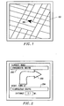
- a vehicle icon 100 is superimposed on a map grid 102.
- the vehicle icon is typically presented in a scale much larger than that of the map grid while many of the street names are not presented on the map grid to avoid cluttering the display with text. Thus, the user only sees an approximation of the vehicle's position.
- a manoeuvre icon 200 may be displayed representing a particular type of manoeuvre (a right turn is shown) along with the names of the street on which the vehicle is proceeding (field 202) and the street at which the upcoming manoeuvre is to be executed (field 204).
- this technique presents information in a more concrete form than described above with reference to Fig. 1, more specific position information is desirable in a variety of situations such as when the vehicle is stopped for a roadside emergency. Important information in such a situation might include, for example, the city in which the vehicle is currently located, the cross streets closest to the current vehicle position (both ahead and behind), and the distance to the next cross street.
- a system to be described by way of example employs a number of display modes which present position and/or navigational information to the user according to different formats. These display modes include a map mode in which a vehicle icon is shown superimposed on a map grid as shown in Fig. 1, and a route guidance mode in which manoeuvre icons are presented to the user for each successive manoeuvre in a predetermined route as shown in Fig. 2.
- the displayed position information includes the city and current road on which the vehicle is located, the nearest cross street, and the distance to the cross street.
- the displayed position information for a stopped vehicle includes the current (or approximate) street address, the city, and the nearest intersections on either side of the vehicle.
- One method will be described, as an example, for displaying information corresponding to a current vehicle position on a display of a vehicle navigation system.
- the system of this method determines the road on which the vehicle is currently located.
- the system then refers to a map database to construct a current road database corresponding to the current road.
- a current road segment corresponding to the current vehicle position is then determined.
- the system then refers to the current road database to determine a first geographical location based on the current road segment.
- the system displays a text representation of the current vehicle position relative to the first geographical location.
- the vehicle's position is initially determined using a global positioning satellite (GPS) system.
- GPS global positioning satellite
- the present invention relates generally to commonly assigned United States Patents No. 5,345,382 to Kao for CALIBRATION METHOD FOR A RELATIVE HEADING SENSOR, No. 5,359,529 to Snider for ROUTE GUIDANCE ON/OFF-ROUTE STATE FILTER, No. 5,374,933 to Kao for POSITION CORRECTION METHOD FOR VEHICLE NAVIGATION SYSTEM, and No. 5,515,283 to Desai for METHOD FOR IDENTIFYING HIGHWAY ACCESS RAMPS FOR ROUTE CALCULATION IN A VEHICLE NAVIGATION SYSTEM.
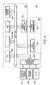
- Fig. 3 is a block diagram of a specific embodiment of a vehicle navigation system 310 for use with the present invention.
- Sensors 312 and 314 and GPS receiver 318 are coupled to computing means 320 through sensor/GPS interface 322.
- mileage sensor 312 comprises an odometer
- angular velocity sensor 314 comprises a gyroscope, or a differential odometer coupled to the wheels of the vehicle.
- a global positioning system (GPS) data receiver 318 is provided for receiving signals from, for example, a satellite-based navigation system. Data from sensor/GPS interface 322 is transmitted to CPU 324, which performs calibration, signal processing, dead-reckoning, vehicle positioning, and route guidance functions.
- GPS global positioning system
- a database containing map information may be stored in database medium 326, with software directing the operation of computing means 320 stored in main memory 328 for execution by CPU 324.
- Memory 328 may comprise read-only memory (ROM),or reprogrammable non-volatile memory such as flash memory or SRAM.
- System RAM 330 permits reading and writing of the information necessary to execute such software programs.
- Database medium 326 may comprise non-volatile memory, a hard disk drive, CD-ROM, or an integrated circuit in which digitized map information has been stored.
- Output controller 332 which may comprise a graphics controller, receives data processed by CPU 324 and transmits the data to display console 340 which includes output communicator 334, usually comprising a display screen.
- the user may input data, such as a desired destination, through user interface 336, typically comprising a keyboard.
- the map database stored in database medium 326 preferably comprises positional data such as, for example, latitude and longitude coordinates, to describe road intersections or nodes, road segments, landmarks and points of interest, and other geographical information.
- the database may further comprise data representing characteristics of roads or places on the map, such as road and place names, road features such as dividers, one-way restrictions, surface, speed limit, shape, elevation, and other properties.
- the map database includes cost values associated with individual nodes and road segments. These cost values correspond to the estimates of time intervals for traversing the respective node or segment. Node cost values take into consideration such information as, for example, whether the vehicle would encounter oncoming traffic, thus delaying a left turn manoeuvre.
- Segment costs reflect road segment characteristics such as speed limit and segment length, both of which affect the travel time along the segment.
- a hierarchy value which relates to the category or type of the road. For example, the highest level category of the hierarchy includes freeways and expressways. The lowest level includes residential streets and/or alleys.
- Fig. 4 is a representation of a display screen 400 which illustrates the type of vehicle position information provided to the user according to a first embodiment of the invention.
- the current road on which the vehicle is located i.e., Innsbruck Drive
- field 402. Below the current road, the type of cross road ahead, i.e., street intersection, is indicated (field 404) as well as the distance to the cross road from the vehicle's current position (field 406).
- the name of the upcoming cross road, i.e., Gibraltar Drive, is indicated in field 408.
- field 410 indicates the city in which the vehicle is located. This display mode may be employed when the vehicle is moving or stopped.
- the information shown on display screen 400 is obtained in the following manner.
- the system first establishes a vehicle position using GPS. It then identifies the city and current road on which the vehicle is located.
- a map database utility then obtains the entire structure of the current road on which the vehicle is currently located and creates a separate database file. Determination of the structure involves identifying each of the nodes and segments in the current road and selected road segments emanating from the nodes of the current road, i.e., the significant intersections.
- the system does not need to refer to the entire map database each time the vehicle's position is updated. This greatly reduces the time which would otherwise be required to update the position information.
- the system may be programmed to repeat this process at regular intervals, e.g., every 0.5 seconds. Alternatively, the system may be configured to display this type of position information each time it is requested by the user.
- the intersection ahead of the current vehicle position is obtained using a node-segment searching algorithm in which the system refers to the separate database file created for the current road.
- the system determines whether there are any road segments attached to the end node of the current segment thereby to determine whether the node represents a cross street of interest. If no such segments are identified, the end node of the next segment in the current road is searched in the same manner. This search algorithm is continued until an appropriate intersection is found or until the search extends more than one mile along the current road from the current vehicle position.
- the extent of the search depends upon the type of road on which the vehicle is travelling.
- the search may extend beyond the one mile limit until an appropriate node, e.g., an exit, is encountered. If, however, the vehicle is on a residential street and the search reaches the one mile limit, the system displays the next minor intersection. If no such intersection exists, the system informs the users that no street exists. Alternatively, if there is a dead end, the system informs the user that a dead end is being approached.
- an appropriate node e.g., an exit
- the system identifies the upcoming intersection using both names.
- the search algorithm encounters a dead end, the user is informed that the current road is not a through street.
- Fig. 5 is a representation of a display screen 500 which illustrates the type of vehicle position information provided to the user in a further arrangement illustrative of the invention.
- the street address and city where the vehicle is currently located are indicated in field 502.
- the street address is determined based on the address range associated with the portion (e.g., block) of the current road on which the vehicle is currently located and the position of the vehicle on that block.
- the address range information is included in the separate database file created for the current road. So, for example, if the vehicle is one-third of the way down the block and the address range is 100-400, the system will display an address of 200.
- Fields 504 and 506 indicate the nearest intersections ahead of and behind the vehicle, respectively.
- Field 508 indicates the distance to the intersection shown in field 504.
- the information in field 504 is obtained using the search algorithm described above with reference to Fig. 4.
- the information in field 506 may be obtained using a similar search algorithm moving backward from the current vehicle position.
- the system may store the most recently passed intersection and update this information each time the vehicle passes the next intersection.
- This display mode may also be used when the vehicle is either moving or stopped. However, it will be understood, that this is more appropriate for stopped vehicles given that a fairly precise location, i.e., a street address is determined.
- Fig. 6 is a task flow diagram 600 which illustrates the manner in which vehicle position information is obtained and updated in one arrangement illustrative of the present invention.
- the user employs the mode key 602 to select a drive information display mode as described with reference to Fig. 4 or Fig. 5.
- Drive information process (DINFO) 604 requests and receives current vehicle position information from vehicle position process (VP) 606 as indicated by arrows 608 and 610, respectively.
- DINFO 604 then calls map database utility (DBU) 612 to obtain information about the upcoming intersection based on the current vehicle position using the database file corresponding to the current road (arrow 614).
- DBU map database utility
- DBU 612 returns the name and type of the cross road corresponding to the intersection and the distance to the cross road from the current vehicle position to DINFO 604 (arrow 616).
- DINFO 604 then sends the information to display module (DM) 618 to be displayed to the user. This may be done periodically if the vehicle is moving, or only once if the vehicle is stopped.
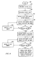
- Fig. 7 is a flowchart illustrating-the operation of a specific embodiment illustrative of the present invention.
- the system determines the current city in which the vehicle is located (step 701), the current road on which the vehicle is proceeding (step 702), and the segment of the current road corresponding to the current vehicle position (step 703).
- a node-segment search as described above with reference to Figs. 4 and 5 is performed from the end node of the road segment (step 704). If an appropriate cross-street is not identified at that node (step 705), the search algorithm proceeds to the next segment in the current road (step 706) and determines whether that segment is within one mile of the current vehicle position (step 707).
- node-segment search is performed. If not, and the vehicle is on a highway (step 708) node-segment searches continue until a cross street is located. If, however, the vehicle is not on the highway, the system determines whether there is a minor intersection or dead end ahead of the vehicle position (step 709). If no such intersection or dead end exists, the system informs the user with the appropriate message (step 710).
- the distance from the current vehicle position to the intersection or dead end is determined (step 711). Finally, the current road, current city, upcoming intersection name (if applicable), and the distance to the intersection or dead end from the current vehicle position are provided to the user on the display of the vehicle navigation system (step 712). This information may be periodically updated, i.e., the process flow periodically repeated, or in response to a user request. It will be understood that this embodiment of the invention may be employed whether the vehicle is moving or not.
- Fig. 8 is a flowchart for use in describing the operation of another arrangement illustrative of the present invention.
- the system determines the current city and road on which the vehicle is located (steps 801 and 802), and the street address corresponding to the current vehicle position (step 803).
- a node-segment search is then performed forward from the current road segment (step 804). If an appropriate cross-street is not identified at the first node (step 805), the search algorithm proceeds to the next segment in the current road (step 806) and performs another node-segment search. If, on the other hand, an appropriate intersection is identified the distance from the current vehicle position to the intersection is determined (step 807).
- Another node-segment search is performed moving backward from the current road segment until the most recently passed intersection is identified (steps 808-810). Finally, the street address, current city, upcoming intersection name, the distance to the upcoming intersection, and the most recently passed intersection are displayed for the user (step 811). It will be understood that this embodiment of the invention is most appropriate for use with a stopped vehicle.
Landscapes
- Engineering & Computer Science (AREA)
- Radar, Positioning & Navigation (AREA)
- Remote Sensing (AREA)
- Automation & Control Theory (AREA)
- Physics & Mathematics (AREA)
- General Physics & Mathematics (AREA)
- Navigation (AREA)
- Traffic Control Systems (AREA)
- Instructional Devices (AREA)
Abstract
Description
- The present invention relates to techniques for displaying position information in a vehicle navigation system. More specifically, the present invention provides methods and apparatus for displaying the current vehicle position relative to a variety of landmarks such as, for example, the nearest intersection.
- Currently available vehicle navigation systems communicate the current vehicle position to users according to a variety of techniques.
- Previously proposed techniques will now be described with reference to Figs. 1 and 2 of the accompanying drawings, in which:-
- Fig. 1 illustrates a technique for displaying vehicle position information in a vehicle navigation system, and
- Fig. 2 illustrates a technique for displaying navigational information in a vehicle navigation system.
-
- In a first technique shown in Fig. 1, a
vehicle icon 100 is superimposed on amap grid 102. - However, because of its abstract format, and because of screen size and map scale limitations, it is sometimes quite difficult for a user who is unfamiliar with a particular geographic area to synthesize data presented according to this technique. That is, the vehicle icon is typically presented in a scale much larger than that of the map grid while many of the street names are not presented on the map grid to avoid cluttering the display with text. Thus, the user only sees an approximation of the vehicle's position.
- Alternatively, as shown in Fig. 2, a
manoeuvre icon 200 may be displayed representing a particular type of manoeuvre (a right turn is shown) along with the names of the street on which the vehicle is proceeding (field 202) and the street at which the upcoming manoeuvre is to be executed (field 204). Unfortunately, even though this technique presents information in a more concrete form than described above with reference to Fig. 1, more specific position information is desirable in a variety of situations such as when the vehicle is stopped for a roadside emergency. Important information in such a situation might include, for example, the city in which the vehicle is currently located, the cross streets closest to the current vehicle position (both ahead and behind), and the distance to the next cross street. This type of information is particularly useful in emergency situations because the user must quickly determine and supply location information to, for example, vehicle towing services, paramedics, or police dispatch. These emergency response resources typically require an address or the nearest cross street to ensure a quick response. Unfortunately, the above described techniques do not present position information in a way that is readily useful in such situations. The technique of Fig. 1 typically does not provide enough detail, while the technique of Fig. 2 only provides information about an approaching landmark as the vehicle is moving. - It is therefore apparent that there is a need for methods and apparatus in a vehicle navigation system which present vehicle position information to the user in a detailed, concise, and easy-to-understand manner.
- There will be described below, by way of example, in illustration of the present invention, methods and apparatus provided in a vehicle navigation system which enable the system to display position information in a variety of formats which are useful in roadside emergencies. A system to be described by way of example employs a number of display modes which present position and/or navigational information to the user according to different formats. These display modes include a map mode in which a vehicle icon is shown superimposed on a map grid as shown in Fig. 1, and a route guidance mode in which manoeuvre icons are presented to the user for each successive manoeuvre in a predetermined route as shown in Fig. 2.
- Various arrangements to be described, as examples, in illustration of the invention, employ other display modes which present vehicle position information relative to nearby landmarks such as intersections and street addresses. For example, in a first display mode, the displayed position information includes the city and current road on which the vehicle is located, the nearest cross street, and the distance to the cross street. In a second display mode, the displayed position information for a stopped vehicle includes the current (or approximate) street address, the city, and the nearest intersections on either side of the vehicle.
- One method will be described, as an example, for displaying information corresponding to a current vehicle position on a display of a vehicle navigation system. The system of this method determines the road on which the vehicle is currently located. The system then refers to a map database to construct a current road database corresponding to the current road. A current road segment corresponding to the current vehicle position is then determined. The system then refers to the current road database to determine a first geographical location based on the current road segment. The system then displays a text representation of the current vehicle position relative to the first geographical location. In one specific illustrative embodiment, the vehicle's position is initially determined using a global positioning satellite (GPS) system.
- The following description and drawings disclose, with reference to Figs. 3 to 8, by means of examples, the invention which is characterised in the appended claims, whose terms determine the extent of the protection conferred hereby.
- In the drawings:-
- Fig. 3 is a block diagram of a vehicle navigation system for use with the present invention;
- Fig. 4 is a representation of a display screen which illustrates the type of vehicle position information provided to the user according to a first embodiment illustrative of the invention,
- Fig. 5 is a representation of a display screen which illustrates the type of vehicle position information provided to the user according to a second embodiment illustrative of the invention,
- Fig. 6 is a task flow diagram which illustrates the manner in which vehicle position information is obtained and updated,
- Fig. 7 is a flowchart illustrating the operation of another embodiment illustrative of the present invention, and
- Fig. 8 is a flowchart for use in illustrating the operation of yet another embodiment illustrative of the invention.
-
- The present invention relates generally to commonly assigned United States Patents No. 5,345,382 to Kao for CALIBRATION METHOD FOR A RELATIVE HEADING SENSOR, No. 5,359,529 to Snider for ROUTE GUIDANCE ON/OFF-ROUTE STATE FILTER, No. 5,374,933 to Kao for POSITION CORRECTION METHOD FOR VEHICLE NAVIGATION SYSTEM, and No. 5,515,283 to Desai for METHOD FOR IDENTIFYING HIGHWAY ACCESS RAMPS FOR ROUTE CALCULATION IN A VEHICLE NAVIGATION SYSTEM.
- Fig. 3 is a block diagram of a specific embodiment of a
vehicle navigation system 310 for use with the present invention.Sensors GPS receiver 318 are coupled to computing means 320 through sensor/GPS interface 322. In typical embodiments,mileage sensor 312 comprises an odometer, andangular velocity sensor 314 comprises a gyroscope, or a differential odometer coupled to the wheels of the vehicle. A global positioning system (GPS)data receiver 318 is provided for receiving signals from, for example, a satellite-based navigation system. Data from sensor/GPS interface 322 is transmitted toCPU 324, which performs calibration, signal processing, dead-reckoning, vehicle positioning, and route guidance functions. A database containing map information may be stored indatabase medium 326, with software directing the operation of computing means 320 stored inmain memory 328 for execution byCPU 324.Memory 328 may comprise read-only memory (ROM),or reprogrammable non-volatile memory such as flash memory or SRAM.System RAM 330 permits reading and writing of the information necessary to execute such software programs.Database medium 326 may comprise non-volatile memory, a hard disk drive, CD-ROM, or an integrated circuit in which digitized map information has been stored.Output controller 332, which may comprise a graphics controller, receives data processed byCPU 324 and transmits the data to displayconsole 340 which includesoutput communicator 334, usually comprising a display screen. The user may input data, such as a desired destination, throughuser interface 336, typically comprising a keyboard. - The map database stored in
database medium 326 preferably comprises positional data such as, for example, latitude and longitude coordinates, to describe road intersections or nodes, road segments, landmarks and points of interest, and other geographical information. The database may further comprise data representing characteristics of roads or places on the map, such as road and place names, road features such as dividers, one-way restrictions, surface, speed limit, shape, elevation, and other properties. According to specific illustrative embodiments, the map database includes cost values associated with individual nodes and road segments. These cost values correspond to the estimates of time intervals for traversing the respective node or segment. Node cost values take into consideration such information as, for example, whether the vehicle would encounter oncoming traffic, thus delaying a left turn manoeuvre. Segment costs reflect road segment characteristics such as speed limit and segment length, both of which affect the travel time along the segment. Also associated with each road in the map database is a hierarchy value which relates to the category or type of the road. For example, the highest level category of the hierarchy includes freeways and expressways. The lowest level includes residential streets and/or alleys. - Fig. 4 is a representation of a
display screen 400 which illustrates the type of vehicle position information provided to the user according to a first embodiment of the invention. The current road on which the vehicle is located, i.e., Innsbruck Drive, is indicated infield 402. Below the current road, the type of cross road ahead, i.e., street intersection, is indicated (field 404) as well as the distance to the cross road from the vehicle's current position (field 406). The name of the upcoming cross road, i.e., Gibraltar Drive, is indicated infield 408. Finally, field 410 indicates the city in which the vehicle is located. This display mode may be employed when the vehicle is moving or stopped. - The information shown on
display screen 400 is obtained in the following manner. The system first establishes a vehicle position using GPS. It then identifies the city and current road on which the vehicle is located. A map database utility then obtains the entire structure of the current road on which the vehicle is currently located and creates a separate database file. Determination of the structure involves identifying each of the nodes and segments in the current road and selected road segments emanating from the nodes of the current road, i.e., the significant intersections. Thus, the system does not need to refer to the entire map database each time the vehicle's position is updated. This greatly reduces the time which would otherwise be required to update the position information. According to various embodiments, the system may be programmed to repeat this process at regular intervals, e.g., every 0.5 seconds. Alternatively, the system may be configured to display this type of position information each time it is requested by the user. - It is important to note that not all road segments emanating from current road nodes are treated in the same way by this utility. Only road segments in certain categories are considered for display as an approaching intersection. More specifically, segments from minor side streets or alley ways are ignored in favour of segments from more readily identifiable roads such as major cross streets, expressways, and freeways. In this way, the user is provided with position information which is practically useful for emergency situations.
- During normal system operation, the intersection ahead of the current vehicle position is obtained using a node-segment searching algorithm in which the system refers to the separate database file created for the current road. The system determines whether there are any road segments attached to the end node of the current segment thereby to determine whether the node represents a cross street of interest. If no such segments are identified, the end node of the next segment in the current road is searched in the same manner. This search algorithm is continued until an appropriate intersection is found or until the search extends more than one mile along the current road from the current vehicle position. According to a specific embodiment, the extent of the search depends upon the type of road on which the vehicle is travelling. If, for example, the vehicle is on a freeway, the search may extend beyond the one mile limit until an appropriate node, e.g., an exit, is encountered. If, however, the vehicle is on a residential street and the search reaches the one mile limit, the system displays the next minor intersection. If no such intersection exists, the system informs the users that no street exists. Alternatively, if there is a dead end, the system informs the user that a dead end is being approached.
- In one specific embodiment, where the search algorithm encounters a "T" with two different intersecting street names emanating from the node, the system identifies the upcoming intersection using both names. In another illustrative embodiment, where the search algorithm encounters a dead end, the user is informed that the current road is not a through street.
- Fig. 5 is a representation of a
display screen 500 which illustrates the type of vehicle position information provided to the user in a further arrangement illustrative of the invention. The street address and city where the vehicle is currently located are indicated infield 502. In one embodiment, the street address is determined based on the address range associated with the portion (e.g., block) of the current road on which the vehicle is currently located and the position of the vehicle on that block. The address range information is included in the separate database file created for the current road. So, for example, if the vehicle is one-third of the way down the block and the address range is 100-400, the system will display an address of 200. -
Fields Field 508 indicates the distance to the intersection shown infield 504. The information infield 504 is obtained using the search algorithm described above with reference to Fig. 4. The information infield 506 may be obtained using a similar search algorithm moving backward from the current vehicle position. Alternatively, the system may store the most recently passed intersection and update this information each time the vehicle passes the next intersection. This display mode may also be used when the vehicle is either moving or stopped. However, it will be understood, that this is more appropriate for stopped vehicles given that a fairly precise location, i.e., a street address is determined. - Fig. 6 is a task flow diagram 600 which illustrates the manner in which vehicle position information is obtained and updated in one arrangement illustrative of the present invention. The user employs the
mode key 602 to select a drive information display mode as described with reference to Fig. 4 or Fig. 5. Drive information process (DINFO) 604 requests and receives current vehicle position information from vehicle position process (VP) 606 as indicated byarrows DINFO 604 then calls map database utility (DBU) 612 to obtain information about the upcoming intersection based on the current vehicle position using the database file corresponding to the current road (arrow 614).DBU 612 returns the name and type of the cross road corresponding to the intersection and the distance to the cross road from the current vehicle position to DINFO 604 (arrow 616).DINFO 604 then sends the information to display module (DM) 618 to be displayed to the user. This may be done periodically if the vehicle is moving, or only once if the vehicle is stopped. - Fig. 7 is a flowchart illustrating-the operation of a specific embodiment illustrative of the present invention. After the VP process determines the vehicle position (see Fig. 6), the system determines the current city in which the vehicle is located (step 701), the current road on which the vehicle is proceeding (step 702), and the segment of the current road corresponding to the current vehicle position (step 703). A node-segment search as described above with reference to Figs. 4 and 5 is performed from the end node of the road segment (step 704). If an appropriate cross-street is not identified at that node (step 705), the search algorithm proceeds to the next segment in the current road (step 706) and determines whether that segment is within one mile of the current vehicle position (step 707). If so, another node-segment search is performed. If not, and the vehicle is on a highway (step 708) node-segment searches continue until a cross street is located. If, however, the vehicle is not on the highway, the system determines whether there is a minor intersection or dead end ahead of the vehicle position (step 709). If no such intersection or dead end exists, the system informs the user with the appropriate message (step 710).
- If an appropriate intersection or dead end is identified the distance from the current vehicle position to the intersection or dead end is determined (step 711). Finally, the current road, current city, upcoming intersection name (if applicable), and the distance to the intersection or dead end from the current vehicle position are provided to the user on the display of the vehicle navigation system (step 712). This information may be periodically updated, i.e., the process flow periodically repeated, or in response to a user request. It will be understood that this embodiment of the invention may be employed whether the vehicle is moving or not.
- Fig. 8 is a flowchart for use in describing the operation of another arrangement illustrative of the present invention. Using the vehicle position generated in the VP process (see Fig. 6), the system determines the current city and road on which the vehicle is located (
steps 801 and 802), and the street address corresponding to the current vehicle position (step 803). A node-segment search is then performed forward from the current road segment (step 804). If an appropriate cross-street is not identified at the first node (step 805), the search algorithm proceeds to the next segment in the current road (step 806) and performs another node-segment search. If, on the other hand, an appropriate intersection is identified the distance from the current vehicle position to the intersection is determined (step 807). Another node-segment search is performed moving backward from the current road segment until the most recently passed intersection is identified (steps 808-810). Finally, the street address, current city, upcoming intersection name, the distance to the upcoming intersection, and the most recently passed intersection are displayed for the user (step 811). It will be understood that this embodiment of the invention is most appropriate for use with a stopped vehicle. - It will be understood that, although particular arrangements illustrative of the invention have been described, by way of example, variations and modifications thereof, as well as other arrangements, may be conceived within the scope of the appended claims.
Claims (19)
- A method for use in displaying information corresponding to the current position of a vehicle on a display of a vehicle navigation system, the method including the steps of(A) determining the current road,(B) referring to a map database to construct a current road database corresponding to the current road,(C) determining a current road segment corresponding to the current position of the vehicle,(D) referring to the current road database to determine a first geographical location based on the current road segment, and(E) displaying a text representation of the current position of the vehicle relative to the first geographical location.
- A method as claimed in claim 1 wherein the first geographical location includes a first intersection near the current position of the vehicle.
- A method as claimed in claim 2 wherein the vehicle is on a route, the first intersection being immediately ahead of the current position of the vehicle on the route.
- A method as claimed in claim 3 including the step of displaying the distance to the first intersection from the current position of the vehicle.
- A method as claimed in claim 1 wherein the steps (C)-(E) are performed periodically.
- A method as claimed in claim 1 wherein the step of referring to the current road database determines a second geographical location, and the text representation of the current position of the vehicle refers to the second geographical location.
- A method as claimed in claim 6 wherein the first and second geographical locations include first and second intersections near to the current position of the vehicle.
- A method as claimed in claim 7 wherein the vehicle is on a route, the first intersection is ahead of the current position of the vehicle on the route, and the second intersection is behind the current position of the vehicle on the route.
- A method as claimed in claim 1 wherein the steps (C)-(E) are performed for a plurality of pairs of intersections on the current road.
- A method as claimed in claim 8 including the step of displaying the distance to the first intersection from the current position of the vehicle.
- A method as claimed in claim 1 wherein the first geographical location includes a street address corresponding to the current position of the vehicle.
- A method as claimed in claim 11 in which the vehicle is stopped on a route, and in which the method includes the step of receiving user input requesting street address information, and the steps (A)-(E) are performed in response to the user input.
- A method as claimed in claim 6 wherein the first and second geographical locations include the street address corresponding to the current position of the vehicle and the first intersection near to the current position of the vehicle.
- A method as claimed in claim 13 wherein the vehicle is on a route, and the first intersection is immediately ahead of the current position of the vehicle on the route.
- A method as claimed in claim 14 including the step of displaying the distance to the first intersection from the current position of the vehicle.
- A method as claimed in claim 1 including the steps of determining whether the current road has changed, and repeating steps (A)-(E) when the current road has changed.
- An apparatus for use in displaying information corresponding to the current position of a vehicle on the display of a vehicle navigation system including(A) means for determining the current road,(B) means for referring to a map database and constructing a current road database corresponding to the current road,(C) means for determining a current road segment corresponding to the current position of the vehicle,(D) means for referring to the current road database and for determining a first geographical location based on the current road segment, and(E) means for displaying a text representation of the current position of the vehicle relative to the first geographical location.
- A vehicle navigation system, including a plurality of sensors for detecting the current position of a vehicle and a vehicle heading, and generating signals indicative thereof, a display for communicating the current vehicle position to a user, a database medium having map data stored therein, and a processor coupled to the sensors, the display, and the database medium, the processor being operable to(A) determine the current road,(B) refer to the database medium and construct a current road database corresponding to the current road,(C) determine a current road segment corresponding to the current position of the vehicle,(D) refer to the current road database and determine a first geographical location based on the current road segment, and(E) display a text representation of the current position of the vehicle relative to the first geographical location.
- A computer program product for use in displaying information corresponding to the current position of a vehicle on a display of a vehicle navigation system, includinga computer-readable medium, anda computer program mechanism embedded in the computer-readable medium for causing a computer to perform the steps of(A) determining the current road,(B) referring to a map database to construct a current road database corresponding to the current road,(C) determining a current road segment corresponding to the current position of the vehicle,(D) referring to the current road database to determine a first geographical location based on the current road segment, and(E) displaying a text representation of the current position of the vehicle relative to the first geographical location.
Applications Claiming Priority (2)
| Application Number | Priority Date | Filing Date | Title |
|---|---|---|---|
| US08/923,502 US6212472B1 (en) | 1997-09-04 | 1997-09-04 | Method and apparatus for displaying current vehicle position |
| US923502 | 1997-09-04 |
Publications (3)
| Publication Number | Publication Date |
|---|---|
| EP0901001A2 true EP0901001A2 (en) | 1999-03-10 |
| EP0901001A3 EP0901001A3 (en) | 2000-06-14 |
| EP0901001B1 EP0901001B1 (en) | 2006-06-28 |
Family
ID=25448792
Family Applications (1)
| Application Number | Title | Priority Date | Filing Date |
|---|---|---|---|
| EP98307104A Expired - Lifetime EP0901001B1 (en) | 1997-09-04 | 1998-09-03 | Method and apparatus for displaying current position of a vehicle |
Country Status (5)
| Country | Link |
|---|---|
| US (1) | US6212472B1 (en) |
| EP (1) | EP0901001B1 (en) |
| JP (1) | JP3217754B2 (en) |
| CA (1) | CA2245986C (en) |
| DE (1) | DE69835055T2 (en) |
Cited By (5)
| Publication number | Priority date | Publication date | Assignee | Title |
|---|---|---|---|---|
| WO2001002807A1 (en) * | 1999-07-02 | 2001-01-11 | Magellan Dis, Inc. | Transmission of vehicle position relative to map database |
| FR2917223A1 (en) * | 2007-06-08 | 2008-12-12 | Thales Sa | Aircraft e.g. Boeing 747, guiding assisting device for airport, has generation unit generating safety set point from topological element, and presentation unit presenting element or associated set point on interface to pilot of aircraft |
| DE10122455B4 (en) * | 2000-05-10 | 2012-02-16 | Denso Corporation | Car navigation system with branch line guidance |
| WO2012080791A1 (en) * | 2010-12-18 | 2012-06-21 | Telefonaktiebolaget L M Ericsson (Publ) | Methods and apparatus for communicating location information for enhancing emergency positioning |
| CN105403226A (en) * | 2015-12-08 | 2016-03-16 | 苏州天擎电子通讯有限公司 | Vehicle-mounted navigation system |
Families Citing this family (47)
| Publication number | Priority date | Publication date | Assignee | Title |
|---|---|---|---|---|
| US6133853A (en) * | 1998-07-30 | 2000-10-17 | American Calcar, Inc. | Personal communication and positioning system |
| US6148261A (en) * | 1997-06-20 | 2000-11-14 | American Calcar, Inc. | Personal communication system to send and receive voice data positioning information |
| US6525768B2 (en) * | 1998-10-21 | 2003-02-25 | American Calcar, Inc. | Positional camera and GPS data interchange device |
| US6965868B1 (en) | 1999-08-03 | 2005-11-15 | Michael David Bednarek | System and method for promoting commerce, including sales agent assisted commerce, in a networked economy |
| US6374184B1 (en) * | 1999-09-10 | 2002-04-16 | Ge-Harris Railway Electronics, Llc | Methods and apparatus for determining that a train has changed paths |
| US6266615B1 (en) * | 1999-09-27 | 2001-07-24 | Televigation, Inc. | Method and system for an interactive and real-time distributed navigation system |
| KR20070046106A (en) * | 1999-10-19 | 2007-05-02 | 아메리칸 캘카어 인코포레이티드 | Technique for effective navigation based on user preferences |
| US6405128B1 (en) | 1999-12-20 | 2002-06-11 | Navigation Technologies Corp. | Method and system for providing an electronic horizon in an advanced driver assistance system architecture |
| US6601073B1 (en) * | 2000-03-22 | 2003-07-29 | Navigation Technologies Corp. | Deductive database architecture for geographic data |
| CA2405060A1 (en) * | 2000-04-11 | 2001-10-18 | American Calcar, Inc. | Gps publication application server |
| JP2004511839A (en) | 2000-07-28 | 2004-04-15 | アメリカン カルカー インコーポレイティド | Technology for organizing and communicating information effectively |
| US6363320B1 (en) * | 2000-08-18 | 2002-03-26 | Geospatial Technologies Inc. | Thin-client real-time interpretive object tracking system |
| US7065446B2 (en) * | 2000-08-18 | 2006-06-20 | Geospatial Technologies, Inc. | Real-time smart mobile device for location information processing |
| US6810323B1 (en) * | 2000-09-25 | 2004-10-26 | Motorola, Inc. | System and method for storing and using information associated with geographic locations of interest to a mobile user |
| US6919866B2 (en) * | 2001-02-06 | 2005-07-19 | International Business Machines Corporation | Vehicular navigation system |
| US6542814B2 (en) * | 2001-03-07 | 2003-04-01 | Horizon Navigation, Inc. | Methods and apparatus for dynamic point of interest display |
| JP4497748B2 (en) * | 2001-04-27 | 2010-07-07 | パイオニア株式会社 | Navigation device, server device for navigation system, destination estimation processing program, and recording medium recording destination estimation processing program |
| JP4402318B2 (en) * | 2001-05-08 | 2010-01-20 | パイオニア株式会社 | Navigation device |
| AU2002310023A1 (en) * | 2001-05-22 | 2002-12-03 | Geospatial Technologies, Inc. | A durable global asset-tracking device and a method of using the same |
| US8392457B1 (en) * | 2001-10-12 | 2013-03-05 | Navteq B.V. | System and method for forming a map database with no-outlet and circular segments |
| JP2003172624A (en) * | 2001-12-10 | 2003-06-20 | Mitsubishi Electric Corp | Apparatus and method for searching intersection |
| US20030142797A1 (en) * | 2001-12-17 | 2003-07-31 | Troy Terrence E. | Information notification system |
| US6859721B1 (en) * | 2001-12-21 | 2005-02-22 | Garmin Ltd. | System, device and method for providing proximate addresses |
| US6691028B2 (en) | 2002-06-07 | 2004-02-10 | Motorola, Inc. | Server-based navigation system and method of operating same |
| US8560223B2 (en) | 2002-08-29 | 2013-10-15 | Mapquest, Inc. | Automated route determination |
| US7202801B2 (en) * | 2002-12-11 | 2007-04-10 | Geospatial Technologies, Inc. | Method and apparatus for an automated location-based, dynamic notification system (ALDNS) |
| JP4013777B2 (en) * | 2003-02-04 | 2007-11-28 | 株式会社デンソー | Car navigation system |
| US9341485B1 (en) * | 2003-06-19 | 2016-05-17 | Here Global B.V. | Method and apparatus for representing road intersections |
| JP4213097B2 (en) * | 2004-09-13 | 2009-01-21 | 三菱電機株式会社 | Car navigation system |
| US7522998B2 (en) * | 2004-11-05 | 2009-04-21 | Johnson Controls Technology Company | System and method for displaying vehicle location information |
| JP2006220562A (en) * | 2005-02-10 | 2006-08-24 | Denso Corp | Car navigation device |
| US20070118284A1 (en) * | 2005-11-23 | 2007-05-24 | Sbc Knowledge Ventures, L.P. | Customized GPS provisioning |
| US8290703B2 (en) * | 2008-01-18 | 2012-10-16 | Mitac International Corporation | Method and apparatus for access point recording using a position device |
| US8700314B2 (en) * | 2008-01-18 | 2014-04-15 | Mitac International Corporation | Method and apparatus to search for local parking |
| US8498808B2 (en) | 2008-01-18 | 2013-07-30 | Mitac International Corp. | Method and apparatus for hybrid routing using breadcrumb paths |
| US20100121518A1 (en) * | 2008-11-11 | 2010-05-13 | Timothy Arthur Tiernan | Map enhanced positioning sensor system |
| US8276159B2 (en) * | 2009-09-23 | 2012-09-25 | Microsoft Corporation | Message communication of sensor and other data |
| US9014960B2 (en) * | 2010-03-29 | 2015-04-21 | Here Global B.V. | Method of operating a navigation system |
| US9063396B2 (en) * | 2012-03-19 | 2015-06-23 | Emily Choi | Integrated photobooth technology for passenger vehicles |
| USD719973S1 (en) * | 2012-06-06 | 2014-12-23 | Apple Inc. | Display screen or portion thereof with graphical user interface |
| USD735214S1 (en) | 2012-11-30 | 2015-07-28 | Google Inc. | Display screen or portion thereof with graphical user interface |
| USD750663S1 (en) | 2013-03-12 | 2016-03-01 | Google Inc. | Display screen or a portion thereof with graphical user interface |
| US8676431B1 (en) | 2013-03-12 | 2014-03-18 | Google Inc. | User interface for displaying object-based indications in an autonomous driving system |
| USD754189S1 (en) | 2013-03-13 | 2016-04-19 | Google Inc. | Display screen or portion thereof with graphical user interface |
| USD754190S1 (en) * | 2013-03-13 | 2016-04-19 | Google Inc. | Display screen or portion thereof with graphical user interface |
| USD757752S1 (en) * | 2014-01-03 | 2016-05-31 | Samsung Electronics Co., Ltd. | Display screen or portion thereof with graphical user interface |
| CN114333378A (en) * | 2021-12-20 | 2022-04-12 | 安波福电子(苏州)有限公司 | System and method for providing location description of vehicle |
Citations (2)
| Publication number | Priority date | Publication date | Assignee | Title |
|---|---|---|---|---|
| EP0434122A1 (en) * | 1989-12-18 | 1991-06-26 | Projectenburo Innosoft B.V. | Method of displaying driving information intended for a driver of a vehicle on a display in said vehicle |
| EP0636863A1 (en) * | 1993-07-27 | 1995-02-01 | Aisin Aw Co., Ltd. | Navigation system |
Family Cites Families (60)
| Publication number | Priority date | Publication date | Assignee | Title |
|---|---|---|---|---|
| US3845289A (en) | 1972-07-18 | 1974-10-29 | Avon Inc | Method and apparatus employing automatic route control system |
| US4672565A (en) | 1981-03-10 | 1987-06-09 | Nippon Soken, Inc. | Direction detecting system for vehicles |
| JPS57169785A (en) | 1981-04-13 | 1982-10-19 | Nissan Motor | Travelling guidance system for car |
| DE3272852D1 (en) | 1981-05-15 | 1986-10-02 | Nippon Denso Co | Navigational apparatus for use in automotive vehicles |
| JPH0619276B2 (en) | 1981-08-17 | 1994-03-16 | 工業技術院長 | Portable map display device assembly |
| JPS58151513A (en) | 1982-03-05 | 1983-09-08 | Alps Electric Co Ltd | Present position updating display of moving body |
| US4797841A (en) | 1983-11-28 | 1989-01-10 | Magnavox Government And Industrial Electronics Company | Method and apparatus for automatic calibration of magnetic compass |
| US4611293A (en) | 1983-11-28 | 1986-09-09 | Magnavox Government And Industrial Electronics Company | Method and apparatus for automatic calibration of magnetic compass |
| US4796191A (en) | 1984-06-07 | 1989-01-03 | Etak, Inc. | Vehicle navigational system and method |
| US4914605A (en) | 1984-10-22 | 1990-04-03 | Etak, Inc. | Apparatus and method for displaying a map |
| US4734863A (en) | 1985-03-06 | 1988-03-29 | Etak, Inc. | Apparatus for generating a heading signal for a land vehicle |
| JPH0650559B2 (en) | 1985-04-03 | 1994-06-29 | 日産自動車株式会社 | Vehicle route guidance device |
| US4751512A (en) | 1986-01-21 | 1988-06-14 | Oceanonics, Inc. | Differential navigation system for remote mobile users |
| US4831563A (en) | 1986-07-01 | 1989-05-16 | Pioneer Electronic Corporation | Method of processing output data from geomagnetic sensor |
| US4862398A (en) | 1986-11-18 | 1989-08-29 | Sumitomo Electric Industries, Ltd. | Correcting method and correcting errors in a terrestrial magnetism heading sensor |
| DE3715007A1 (en) | 1987-05-06 | 1988-11-17 | Bosch Gmbh Robert | METHOD AND DEVICE FOR DETERMINING THE COURSE OF A LAND VEHICLE |
| DE3853611T2 (en) | 1987-05-11 | 1996-01-18 | Sumitomo Electric Industries | POSITION DETECTION SYSTEM. |
| DE3719017A1 (en) | 1987-06-06 | 1988-12-15 | Bosch Gmbh Robert | METHOD AND DEVICE FOR DETERMINING A DRIVING ROUTE BETWEEN A START POINT AND A DESTINATION POINT |
| NL8702087A (en) | 1987-09-04 | 1989-04-03 | Philips Nv | VEHICLE NAVIGATION DEVICE WITH DISPLAY OF A SELECTED MAP ELEMENT ACCORDING TO A PRE-DEFINED REPRESENTATION STANDARD. |
| US4964052A (en) | 1987-10-30 | 1990-10-16 | Nec Home Electronics Ltd. | Navigation device for use in a vehicle |
| JP2680318B2 (en) | 1987-12-28 | 1997-11-19 | アイシン・エィ・ダブリュ株式会社 | Navigation device |
| JPH01173824A (en) | 1987-12-28 | 1989-07-10 | Aisin Aw Co Ltd | Navigation device for vehicle with help function |
| JP2637446B2 (en) | 1987-12-28 | 1997-08-06 | アイシン・エィ・ダブリュ株式会社 | Navigation device |
| JPH01214711A (en) | 1988-02-23 | 1989-08-29 | Toshiba Corp | Navigation apparatus |
| JPH023900A (en) | 1988-06-16 | 1990-01-09 | Nissan Motor Co Ltd | Present place displaying device for moving body |
| JPH07117420B2 (en) | 1988-06-27 | 1995-12-18 | パイオニア株式会社 | Road data generation method in vehicle-mounted navigation device |
| JPH07119617B2 (en) | 1988-07-05 | 1995-12-20 | マツダ株式会社 | Vehicle navigation system |
| US4918609A (en) | 1988-10-11 | 1990-04-17 | Koji Yamawaki | Satellite-based position-determining system |
| US5060162A (en) | 1988-12-09 | 1991-10-22 | Matsushita Electric Industrial Co., Ltd. | Vehicle in-situ locating apparatus |
| US5287297A (en) | 1989-11-02 | 1994-02-15 | Matsushita Electric Industrial Co., Ltd. | Magnetic direction finder with correcting circuit |
| US5323321A (en) * | 1990-06-25 | 1994-06-21 | Motorola, Inc. | Land vehicle navigation apparatus |
| US5177685A (en) | 1990-08-09 | 1993-01-05 | Massachusetts Institute Of Technology | Automobile navigation system using real time spoken driving instructions |
| EP0485132B1 (en) | 1990-11-06 | 1996-03-06 | Fujitsu Ten Limited | Direction sensor having an earth magnetism sensor and a rate gyro sensor and navigation system having this direction sensor |
| DE69129892T2 (en) | 1990-11-09 | 1999-03-18 | Sumitomo Electric Industries | Device for an inexpensive route selection |
| JPH04315913A (en) | 1991-04-16 | 1992-11-06 | Pioneer Electron Corp | Vehicle bearing measuring device |
| US5272638A (en) | 1991-05-31 | 1993-12-21 | Texas Instruments Incorporated | Systems and methods for planning the scheduling travel routes |
| JP2771911B2 (en) | 1991-08-09 | 1998-07-02 | 三菱電機株式会社 | Car navigation system |
| JP2782135B2 (en) | 1991-12-18 | 1998-07-30 | 本田技研工業株式会社 | Vehicle travel guidance device |
| JP2673403B2 (en) | 1992-06-23 | 1997-11-05 | 本田技研工業株式会社 | Route search device |
| US5444629A (en) * | 1992-07-20 | 1995-08-22 | Aisin Aw Co. | Vehicle-guiding device for recognizing curved road and leading vehicle along curved road aurally |
| DE69331485T2 (en) * | 1992-08-19 | 2002-06-20 | Aisin Aw Co | Navigation system for vehicles |
| DE4334701C2 (en) | 1992-10-12 | 1997-01-16 | Maspro Denko Kk | Navigation system and navigation method with a route determination process that is able to determine a desired route quickly and completely |
| JP2834952B2 (en) | 1992-10-22 | 1998-12-14 | アルパイン株式会社 | Route search method |
| JPH06222125A (en) | 1993-01-22 | 1994-08-12 | Sumitomo Electric Ind Ltd | On-vehicle navigation device |
| JPH06309595A (en) | 1993-04-26 | 1994-11-04 | Pioneer Electron Corp | Navigator |
| US5412573A (en) | 1993-05-20 | 1995-05-02 | Motorola Inc. | Multi-mode route guidance system and method therefor |
| JP3528926B2 (en) | 1993-05-26 | 2004-05-24 | 三菱電機株式会社 | Car navigation system |
| JP3302445B2 (en) | 1993-06-18 | 2002-07-15 | パイオニア株式会社 | Navigation device |
| JPH0727568A (en) | 1993-07-09 | 1995-01-27 | Zanabui Informatics:Kk | Path guiding device and path searching method |
| US5519619A (en) | 1994-03-14 | 1996-05-21 | Motorola, Inc. | Route planning method for hierarchical map routing and apparatus therefor |
| JP3520558B2 (en) | 1994-04-27 | 2004-04-19 | 松下電器産業株式会社 | Positioning device |
| JPH0886660A (en) * | 1994-09-16 | 1996-04-02 | Alpine Electron Inc | Car navigation system |
| JPH08320648A (en) * | 1995-05-24 | 1996-12-03 | Matsushita Electric Ind Co Ltd | Navigation device |
| JP3533767B2 (en) | 1995-07-17 | 2004-05-31 | 株式会社デンソー | Vehicle navigation system |
| US5729109A (en) * | 1995-07-19 | 1998-03-17 | Matsushita Electric Industrial Co., Ltd. | Navigation system and intersection guidance method |
| JP3448134B2 (en) * | 1995-08-25 | 2003-09-16 | アイシン・エィ・ダブリュ株式会社 | Vehicle navigation system |
| US5874905A (en) * | 1995-08-25 | 1999-02-23 | Aisin Aw Co., Ltd. | Navigation system for vehicles |
| KR0183524B1 (en) * | 1995-09-27 | 1999-04-15 | 모리 하루오 | Navigation system for displaying a structure-shape map 51 g08g 1/0969 |
| KR100235240B1 (en) * | 1995-10-31 | 1999-12-15 | 모리 하루오 | Navigation apparatus |
| US5839088A (en) * | 1996-08-22 | 1998-11-17 | Go2 Software, Inc. | Geographic location referencing system and method |
-
1997
- 1997-09-04 US US08/923,502 patent/US6212472B1/en not_active Expired - Lifetime
-
1998
- 1998-08-26 CA CA002245986A patent/CA2245986C/en not_active Expired - Fee Related
- 1998-09-03 EP EP98307104A patent/EP0901001B1/en not_active Expired - Lifetime
- 1998-09-03 DE DE69835055T patent/DE69835055T2/en not_active Expired - Fee Related
- 1998-09-04 JP JP25125198A patent/JP3217754B2/en not_active Expired - Fee Related
Patent Citations (2)
| Publication number | Priority date | Publication date | Assignee | Title |
|---|---|---|---|---|
| EP0434122A1 (en) * | 1989-12-18 | 1991-06-26 | Projectenburo Innosoft B.V. | Method of displaying driving information intended for a driver of a vehicle on a display in said vehicle |
| EP0636863A1 (en) * | 1993-07-27 | 1995-02-01 | Aisin Aw Co., Ltd. | Navigation system |
Non-Patent Citations (2)
| Title |
|---|
| DINGUS T A: "HUMAN FACTORS ENGINEERING THE TRAVTEK DRIVER INTERFACE" PROCEEDINGS OF THE VEHICLE NAVIGATION AND INFORMATION SYSTEMS CONFERENCE,US,NEW YORK, IEEE, vol. -, 1991, pages 749-755, XP000357146 ISBN: 0-7803-0488-8 * |
| KIRSON A M: "A COMPACT DRIVER INTERFACE FOR NAVIGATION AND ROUTE GUIDANCE" PACIFIC RIM TRANSTECH CONFERENCE. VEHICLE NAVIGATION AND INFORMATION SYSTEMS CONFERENCE PROCEEDINGS,US,NEW YORK, IEEE, vol. CONF. 6, 1995, pages 61-66, XP000641135 ISBN: 0-7803-2588-5 * |
Cited By (7)
| Publication number | Priority date | Publication date | Assignee | Title |
|---|---|---|---|---|
| WO2001002807A1 (en) * | 1999-07-02 | 2001-01-11 | Magellan Dis, Inc. | Transmission of vehicle position relative to map database |
| DE10122455B4 (en) * | 2000-05-10 | 2012-02-16 | Denso Corporation | Car navigation system with branch line guidance |
| FR2917223A1 (en) * | 2007-06-08 | 2008-12-12 | Thales Sa | Aircraft e.g. Boeing 747, guiding assisting device for airport, has generation unit generating safety set point from topological element, and presentation unit presenting element or associated set point on interface to pilot of aircraft |
| US7999699B2 (en) | 2007-06-08 | 2011-08-16 | Thales | System for aiding the guidance of an aircraft on an airport |
| WO2012080791A1 (en) * | 2010-12-18 | 2012-06-21 | Telefonaktiebolaget L M Ericsson (Publ) | Methods and apparatus for communicating location information for enhancing emergency positioning |
| US9277384B2 (en) | 2010-12-18 | 2016-03-01 | Telefonaktiebolaget L M Ericsson (Publ) | Methods and apparatus for communicating location information for enhancing emergency positioning |
| CN105403226A (en) * | 2015-12-08 | 2016-03-16 | 苏州天擎电子通讯有限公司 | Vehicle-mounted navigation system |
Also Published As
| Publication number | Publication date |
|---|---|
| JP3217754B2 (en) | 2001-10-15 |
| DE69835055D1 (en) | 2006-08-10 |
| CA2245986A1 (en) | 1999-03-04 |
| JPH11148831A (en) | 1999-06-02 |
| EP0901001B1 (en) | 2006-06-28 |
| CA2245986C (en) | 2002-04-30 |
| DE69835055T2 (en) | 2006-11-16 |
| EP0901001A3 (en) | 2000-06-14 |
| US6212472B1 (en) | 2001-04-03 |
Similar Documents
| Publication | Publication Date | Title |
|---|---|---|
| EP0901001B1 (en) | Method and apparatus for displaying current position of a vehicle | |
| EP0945707B1 (en) | Method and apparatus for route calculation | |
| KR100281293B1 (en) | Route determination method of vehicle navigation system | |
| US6381537B1 (en) | Method and system for obtaining geographic data using navigation systems | |
| EP0836074B1 (en) | Route guidance system and method for use in vehicle navigation | |
| JP4995499B2 (en) | Map information distribution system | |
| JP3413087B2 (en) | Method and apparatus for guiding a nearby route by a vehicle navigation system | |
| US6456931B1 (en) | Indicating directions to destination and intermediate locations in vehicle navigation systems | |
| US5731978A (en) | Method and apparatus for enhancing vehicle navigation through recognition of geographical region types | |
| EP0689034B1 (en) | Method for identifying highway access ramps for route calculation in a vehicle navigation system | |
| US6226590B1 (en) | Vehicular navigation system and storage medium | |
| JP4983660B2 (en) | Navigation system and route search method | |
| EP0840269A1 (en) | Method and apparatus for use in a vehicle navigation system | |
| JP3754110B2 (en) | Dynamic route search method and navigation apparatus | |
| EP3561453B1 (en) | Method, apparatus and computer program product for determining likelihood of a route | |
| JP2006512587A (en) | Route calculation around traffic obstacles using marked detours | |
| EP1078222A1 (en) | Method for displaying a current vehicle location using a navigation system | |
| JP2008096339A (en) | Traffic information delivery system | |
| WO2007037281A1 (en) | Surrounding area search data creating system, surrounding area search system, surrounding area search data creating method, surrounding area search method, and navigation device | |
| MX2007015265A (en) | Method for determining traffic information, and a device arranged to perform the method. | |
| US20220170760A1 (en) | Method, apparatus, and computer program product for anonymized estimation of parking availability | |
| US20220034667A1 (en) | Method, apparatus, and computer program product for estimating a time-of-arrival at a destination | |
| JP2007327970A (en) | Route calculus of area around traffic bottleneck using marked detour | |
| US11624629B2 (en) | Method, apparatus, and computer program product for generating parking lot geometry | |
| KR100877279B1 (en) | Route calculation around traffic obstacles using marked diversions |
Legal Events
| Date | Code | Title | Description |
|---|---|---|---|
| PUAI | Public reference made under article 153(3) epc to a published international application that has entered the european phase |
Free format text: ORIGINAL CODE: 0009012 |
|
| 17P | Request for examination filed |
Effective date: 19980924 |
|
| AK | Designated contracting states |
Kind code of ref document: A2 Designated state(s): DE FR GB |
|
| AX | Request for extension of the european patent |
Free format text: AL;LT;LV;MK;RO;SI |
|
| RAP1 | Party data changed (applicant data changed or rights of an application transferred) |
Owner name: VISTEON TECHNOLOGIES, LLC |
|
| PUAL | Search report despatched |
Free format text: ORIGINAL CODE: 0009013 |
|
| AK | Designated contracting states |
Kind code of ref document: A3 Designated state(s): AT BE CH CY DE DK ES FI FR GB GR IE IT LI LU MC NL PT SE |
|
| AX | Request for extension of the european patent |
Free format text: AL;LT;LV;MK;RO;SI |
|
| AKX | Designation fees paid |
Free format text: DE FR GB |
|
| GRAP | Despatch of communication of intention to grant a patent |
Free format text: ORIGINAL CODE: EPIDOSNIGR1 |
|
| GRAS | Grant fee paid |
Free format text: ORIGINAL CODE: EPIDOSNIGR3 |
|
| GRAA | (expected) grant |
Free format text: ORIGINAL CODE: 0009210 |
|
| AK | Designated contracting states |
Kind code of ref document: B1 Designated state(s): DE FR GB |
|
| REG | Reference to a national code |
Ref country code: GB Ref legal event code: FG4D |
|
| REF | Corresponds to: |
Ref document number: 69835055 Country of ref document: DE Date of ref document: 20060810 Kind code of ref document: P |
|
| PGFP | Annual fee paid to national office [announced via postgrant information from national office to epo] |
Ref country code: GB Payment date: 20060921 Year of fee payment: 9 |
|
| PGFP | Annual fee paid to national office [announced via postgrant information from national office to epo] |
Ref country code: FR Payment date: 20060922 Year of fee payment: 9 |
|
| PGFP | Annual fee paid to national office [announced via postgrant information from national office to epo] |
Ref country code: DE Payment date: 20060926 Year of fee payment: 9 |
|
| ET | Fr: translation filed | ||
| PLBE | No opposition filed within time limit |
Free format text: ORIGINAL CODE: 0009261 |
|
| STAA | Information on the status of an ep patent application or granted ep patent |
Free format text: STATUS: NO OPPOSITION FILED WITHIN TIME LIMIT |
|
| 26N | No opposition filed |
Effective date: 20070329 |
|
| GBPC | Gb: european patent ceased through non-payment of renewal fee |
Effective date: 20070903 |
|
| PG25 | Lapsed in a contracting state [announced via postgrant information from national office to epo] |
Ref country code: DE Free format text: LAPSE BECAUSE OF NON-PAYMENT OF DUE FEES Effective date: 20080401 |
|
| REG | Reference to a national code |
Ref country code: FR Ref legal event code: ST Effective date: 20080531 |
|
| PG25 | Lapsed in a contracting state [announced via postgrant information from national office to epo] |
Ref country code: FR Free format text: LAPSE BECAUSE OF NON-PAYMENT OF DUE FEES Effective date: 20071001 |
|
| PG25 | Lapsed in a contracting state [announced via postgrant information from national office to epo] |
Ref country code: GB Free format text: LAPSE BECAUSE OF NON-PAYMENT OF DUE FEES Effective date: 20070903 |