EP0863631A2 - Tondatenübertragung und Aufzeichnung - Google Patents
Tondatenübertragung und Aufzeichnung Download PDFInfo
- Publication number
- EP0863631A2 EP0863631A2 EP98301491A EP98301491A EP0863631A2 EP 0863631 A2 EP0863631 A2 EP 0863631A2 EP 98301491 A EP98301491 A EP 98301491A EP 98301491 A EP98301491 A EP 98301491A EP 0863631 A2 EP0863631 A2 EP 0863631A2
- Authority
- EP
- European Patent Office
- Prior art keywords
- gap
- signal
- spectrum
- audio signal
- audio
- Prior art date
- Legal status (The legal status is an assumption and is not a legal conclusion. Google has not performed a legal analysis and makes no representation as to the accuracy of the status listed.)
- Withdrawn
Links
Images


Classifications
-
- H—ELECTRICITY
- H04—ELECTRIC COMMUNICATION TECHNIQUE
- H04H—BROADCAST COMMUNICATION
- H04H20/00—Arrangements for broadcast or for distribution combined with broadcast
- H04H20/28—Arrangements for simultaneous broadcast of plural pieces of information
- H04H20/30—Arrangements for simultaneous broadcast of plural pieces of information by a single channel
- H04H20/31—Arrangements for simultaneous broadcast of plural pieces of information by a single channel using in-band signals, e.g. subsonic or cue signal
-
- H—ELECTRICITY
- H04—ELECTRIC COMMUNICATION TECHNIQUE
- H04B—TRANSMISSION
- H04B1/00—Details of transmission systems, not covered by a single one of groups H04B3/00 - H04B13/00; Details of transmission systems not characterised by the medium used for transmission
- H04B1/69—Spread spectrum techniques
- H04B1/707—Spread spectrum techniques using direct sequence modulation
- H04B1/7073—Synchronisation aspects
Definitions
- This invention relates to audio data transmission and recording.
- digital audio apparatuses such as a compact disc (CD) player and a so-called mini disc (MD) using a small-size optical disc are widely spread, enabling to easily reproduce an audio signal of a high quality.
- CD compact disc
- MD mini disc
- a copy inhibit control signal consisting of a copy inhibit symbol or a copy generation limit symbol as well as an author right data are additionally recorded in additional to a digital audio signal on a recording medium, so as to prevent copying or to trace a recording medium copied using an authorized data.
- a method called matched filter for improving the synchronization establishment in a dedicated circuit.
- the circuit size becomes great and it is not practical in costs to mount such a circuit in a reproduction apparatus and a reception apparatus.
- a method desired is one which is easily available at a low price and can be used in common for various apparatuses. Because of these problems, it has been considered difficult to realize a data multiplexing using the spectrum diffusion method.
- An audio data transmission apparatus includes gap insert position detecting means and gap insert means, so that a gap is inserted by the gap inserting means at a position detected by the gap insert position detecting means.
- This gap is used as a control signal for multiplexing on the audio signal a spectrum-diffused data obtained according to an additional information.
- an audio data recording apparatus uses as a control signal the gap from the gap detection means, so that demodulation means demodulates a spectrum-diffused data multiplexed on an audio signal, and according to the demodulated additional information, correction means correct the spectrum-diffused data.
- an audio data recording medium contains an additional information as a spectrum-diffused data which is multiplexed on an audio signal using a gap as a control signal.
- a preferred form of implementation of the present invention described below provides an audio data transmission apparatus and method, an audio data recording apparatus, and an audio data recording medium which are capable of multiplexing spectrum-diffused data on an analog audio signal with the least deterioration of the audio quality.
- the preferred form of implementation of the present invention provides an audio data transmission apparatus and method for transmitting, over audio data, additional information such as a copy inhibit control signal and author right information for tracing an unauthorized copy; an audio data recording apparatus for recording the audio data which has been received; and an audio data recording medium containing the additional information overwritten on the audio data.
- Fig. 1 is a block diagram showing an audio data transmission apparatus and method according to an embodiment of the present invention.
- Fig. 2 is a timing chart for explanation of an example of controlling a spectrum diffusion signal by way of a gap width modulation using the aforementioned embodiment shown in Fig. 1.
- Fig. 3 is a timing chart for explanation of a time division transmission of a spectrum diffusion signal using the aforementioned embodiment of Fig. 1.
- Fig. 4 is a block diagram showing an audio data reproduction apparatus according to an embodiment of the present invention.
- Fig. 5 is a timing chart for explanation of a demodulation procedure of a spectrum diffusion signal using the aforementioned embodiment of Fig. 4.
- Fig. 6 is a block diagram showing an audio data transmission apparatus and method according to another embodiment of the present invention.
- Fig. 7 is a flowchart for explanation of the operation of the embodiment of Fig. 6.
- Fig. 8 is a timing chart for explanation of control of a spectrum diffusion signal by way of a gap signal of the embodiment shown in Fig. 6.
- Fig. 9 is a timing chart for explanation of a specific example in which a spectrum diffusion signal is selectively inserted in a portion of an audio signal having a large amplitude and a wide band width where the masking effect can be expected in the embodiment of Fig. 6.
- Fig. 10 is a timing chart for explanation of a specific example of other operation in the embodiment of Fig. 6.
- Fig. 11 shows a waveform for explanation of frequency band limit in a spectrum diffusion signal so as to cope with transmission deterioration due to the audio compression technique.
- Fig. 12 shows a specific example of a data insertion according to the embodiment of Fig. 6.
- Fig. 13 shows another specific example of data insertion according to the embodiment of Fig. 6.
- Fig. 14 is a block diagram showing an audio data reproduction apparatus according to still another embodiment of the present invention.
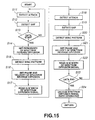
- Fig. 15 is a timing chart explaining the operation of the embodiment of the aforementioned Fig. 14.
- Fig. 16 is a block diagram showing an audio data recording apparatus according to yet another embodiment of the present invention.
- This transmission apparatus is for multiplexing on an analog audio signal an additional information such as a copy prevention control signal or author right information which has been made into a spectrum-diffused data, and includes an encoder 1 shown in Fig. 1.
- This encoder 1 includes: a modulator 3 for carrying out a spectrum diffusion on a data input Di which is the aforementioned additional information supplied through a data input terminal 2; a gap insert position detection block 7 for detecting a position allowing a gap insertion in an audio signal input Si supplied from a signal input terminal 6; a gap inserter 8 for inserting the gap at the insertion position detected by this gap insert position detection block 7; and a modulation signal adder 9 for multiplexing the spectrum-diffused data on the audio signal Si using as a control signal the gap which has been inserted by the gap inserter 8.
- the input data Di is subjected to spectrum diffusion in the modulator 3 and continuously written into a first-in first-out (FIFO) 5 by a write control signal (WE) supplied from a memory control block 4.
- FIFO first-in first-out
- WE write control signal
- a gap is inserted from the gap inserter 8 at a gap insert start position detected by the gap insert position detection block 7 in the audio signal Si supplied from the input terminal 6.
- An embedded data Dem divided from the FIFO 5 by a read-out control signal (RE) from the memory control block 4 is added by the modulation signal adder 9 after the aforementioned gap on the audio signal for output as an audio signal output So from an output terminal 10.
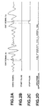
- a specific example of multiplexing a spectrum diffusion signal on the audio signal using this encoder 1 will be explained with reference to Fig. 2.
- the width of a gap signal G1 and the width of a gap signal G2 are varied so as to be respectively defined as a start pulse in Fig. 2B and a stop pulse in Fig. 2C, so that a spectrum diffusion signal is multiplexed between the gap signal G1 and the gap signal G2 on the audio signal shown in Fig. 2A.
- Fig. 3 explains another specific example of using this encoder 1 for dividing and multiplexing the spectrum diffusion signal on the audio signal.
- the spectrum diffusion signal shown in Fig. 3A is time-divided at a predetermined length as shown in Fig. 3B, so that each division is multiplexed on the audio signal after a start pulse of Fig. 3C.
- the spectrum diffusion signal which has been time-divided and transmitted by the encoder 1 is demodulated according to the aforementioned gap by a decoder shown in Fig. 4.
- the decoder 11 is supplied with an audio signal input So (multiplexed with the spectrum diffusion signal) through a signal input terminal 12, from which the gap serving as the aforementioned start pulse is detected by a gap detector 13 and is supplied to a memory control block 14.
- the memory control block 14 supplies a write control signal (WE) to a FIFO 16 so that a modulation signal which has been isolated from the audio signal by a modulation signal isolator 15 is intermittently written into the FIFO 16.
- the memory control block 14 supplies a read-out control signal to the FIFO 16 so that the aforementioned modulation signal is returned to a continuous spectrum diffusion signal as shown in Fig. 5B which is supplied to a demodulator 17.
- the demodulator 17 carries out a reverse spectrum diffusion onto the aforementioned continuous modulation signal, so as to be made back to the previous additional information data Do.
- the memory may be other than the FIFO memory if it is possible to control to carry out the same thing.
- Fig. 6 shows an encoder 20 including a modulator 29 having a memory function or a shift register function.
- An audio signal Si supplied through a signal input terminal 21 is firstly supplied to an envelope detection block 23 constituting a gap insert position detection block 22.
- This envelope detection block 23 detects an attack portion equal to or above a predetermined level in the audio signal input Si.
- the aforementioned audio signal input Si is also supplied to a spectrum analysis block 24 constituting the aforementioned gap insert position detection block 22, so as to detect a discontinuous portion of a spectrum immediately before the aforementioned attack portion.
- the envelope detection block 24 detects a portion having a sufficiently small amplitude.
- the aforementioned audio signal input Si is also supplied to a delay circuit 26.
- the input audio signal delayed by this delay circuit 26 is supplied to a gap inserter 27.
- This gap inserter 27 is controlled by a controller 25.
- the controller 25 determines a position enabling insert of the aforementioned gap according to the detection outputs from the envelope detection block 23 and the spectrum analysis block 24 of the aforementioned gap insert detection block 22, and makes to insert the aforementioned gap at the position determined from the gap inserter 27.
- This gap is used as a control signal for a spectrum diffusion signal which will be recorded after this.
- the data input Di to be embedded in the aforementioned audio signal is supplied through a data input terminal 28 to a modulator 29.
- the modulator 29 carried out a spectrum diffusion onto the aforementioned data input Di, which is temporarily recorded in the modulator 29 together with the synchronization, start, stop control timings.
- a predetermined width or a division is outputted from the modulator 29 and added by a mixer 30 to the audio signal, which is outputted as an audio signal output So from an output terminal 31.
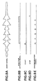
- Fig. 7 is a flowchart showing the operation of this encoder. That is, in steps S1 to S3. a gap insert position is detected by the gap insert position detection block 22, and instep S4, the modulator 29 is used to write into a waveform of a spectrum diffused data according to the data input Di. If in step S2 a frequency spectrum immediately before the attack is not found to be discontinuous and if in step S3 the amplitude is not found sufficiently small, control is passed to step S5 where a waveform dedicated for synchronization is written.
- this encoder 20 it is possible to selectively multiplex a spectrum diffusion signal at arbitrary positions and to restore them as a continuous signal.
- the gap signal has several values according to the width, level, and waveform, so as to realize functions of a start, stop, synchronization signal, and synchronization protection.
- a start signal is inserted as shown in Fig. 8C, from which the spectrum diffusion recording is started as shown in Fig. 8B, and the recording is terminated by a stop signal at the timing shown in Fig. 8D.
- a synchronous signal or a signal of synchronization protection is inserted as shown in Fig. 8E.
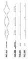
- Fig. 9 shows a specific example of selectively inserting a spectrum diffusion signal at such a portion of a great amplitude and band width where the masking effect can be expected according to the audio signal amplitude. That is, a start pulse shown in Fig. 9C and a stop pulse shown in Fig. 9D are used to divide a spectrum diffusion signal as shown in Fig. 9B, so as to be multiplexed in the portions having a great amplitude in the audio signal shown in Fig. 9A.
- the S/N for the hearing sense is improved by not inserting the spectrum diffusion signal in a small signal portion and a narrow band of a music signal.
- Fig. 10 shows a specific example of dividing the spectrum diffusion signal into blocks of a predetermined width and defining a start with a gap signal or a sync pattern for synchronization derived from the gap signal. That is, when multiplexing a spectrum diffusion signal on an audio signal as shown in Fig. 10A, if the stop signal position cannot be allocated at a preferable position due to the audio signal, only a start pulse is generated as shown in Fig. 10B and, as shown in Fig. 10C, the spectrum diffusion signal is recorded for a width of W from a position apart from the start pulse by an offset "a". This method is more preferable in most cases of music sources.
- the block unit may be a chip interval (1 bit interval width of a modulation signal) multiplied by an integer, or a bit interval width (modulation signal interval width) multiplied by an integer.
- the block width is determined in advance, it is possible to divide a continuous spectrum diffusion signal only by defining a start, so as to be recorded at arbitrary positions, which can also be reproduced.
- the recording level of the spectrum diffusion signal is varied according to the recorded sound level. During a reproduction, this variation is detected by the envelope detector so as to realize the previous uniform level.
- This method can also be utilized to reduce the deterioration of the transmission characteristic of the additional information caused when the linearity of a previous sound signal is processed by a dynamic system such as a limitter, noise reduction, AGC and the like.
- Fig. 10D shows a specific example of varying the recording level of the spectrum diffusion signal in accordance with the audio signal amplitude. This enables to prevent the error rate deterioration due to the fluctuation of the recording level of the recorded spectrum diffusion signal caused by an audio processing by a dynamic system such as a limitter and a noise reduction.
- a dynamic system such as a limitter and a noise reduction.
- An audio compression technique such as the MPEG/ATRAC/AC-3 affects the spectrum diffusion signal multiplexed. Especially in an attack portion where an audio signal increases its data amount and in a portion having a very wide frequency band, a part of the spectrum diffusion signal having no correlation with the audio signal is deleted as a result of compression and cannot be correctly transmitted. To cope with this, in the present system , the spectrum diffusion signal is recorded in areas other than those areas where the audio data amount is concentrated.
- the first method is to record a spectrum diffusion signal with a predetermined time lapse after a start signal defined by a gap.
- compression on subband is carried out on a block unit of 512 or 1024 samples. Consequently, when embedding a gap, it is possible to select the start position of the spectrum diffusion signal, eliminating the audio signal attack portion, so as to reduce the affects from the transmission deterioration.
- the transmission deterioration due to compression also occurs when the frequency band is wide. Consequently, it is possible to reduce the deterioration by selecting a position of a gap signal so that the spectrum diffusion signal can start at other than the aforementioned wide frequency band portion.
- the encoder 20 in Fig. 6 includes the gap insert position detection block 22 which detects an attack portion and a wide band region of the audio signal and a control signal defined by a gap is embedded by the gap inserter 27 evading such portions, so as to selectively multiplex the spectrum diffusion signal.
- frequency components of the intermediate and lower zones have a higher priority.
- a zone up to 5 kHz is least affected by compression. Consequently, as shown in Fig. 11, it is possible to select the spectrum diffusion signal in the zone up to 5 kHz or limiting the zone before multiplexing, so as to reduce the transmission deterioration due to compression.
- the spectrum diffusion because of its characteristic, cannot be detected if a medium having the spectrum diffusion is reproduced at a velocity changing more than a certain range. This problem cannot be solved unless the chip interval length of the spectrum diffusion signal can be determined during decoding. Tracing should be repeated while changing the chip interval or parallel detection should be carried out with several width values simultaneously.
- the present system divides the spectrum diffusion signal into shorter intervals so that the intervals can be synchronized with a gap, enabling to adjust for the velocity change easier than the original spectrum diffusion signal. For example, if the spectrum diffusion signal is divided into 1/10 intervals, the allowable deviation is improved by 10 times. Thus, reproduction velocity deviation allowed is significantly mitigated.
- the synchronization method for the velocity system can also be improved.
- This is a method of recording a sync pattern for synchronization immediately after a gap, or on a gap, or at predetermined interval positions.
- the sync pattern may be a burst-type continuous wave, but considering the affects on the hearing sense, it is preferable to use a fixed pattern similar to a random noise.
- the decoder detects the gap and reads the sync pattern, so as to determine a correct chip interval, which is followed by the spectrum-diffused data portion.
- the spectrum diffusion signal divided into blocks which are written into a memory, and when read out, they are again made into a continuous signal for supply to the decoder.
- the synchronization signal of the spectrum diffusion signal itself is written in the gap signal or the sync pattern, which enables to obtain synchronization instantaneously, starting demodulation (reverse diffusion) of the data.
- Fig. 12 shows a specific example of a pattern indicating the spectrum diffusion chip interval width multiplexed in the gap interval AB.
- the interval GH represents a data portion of the spectrum diffusion.
- Fig. 13 shows a specific example in which the gap interval AB is followed by an offset interval CD for coping with the compression; the interval EF is multiplexed with a pattern indicating information of spectrum diffusion velocity and phase; and the interval GH represents the spectrum diffusion data portion.
- This example includes a time width CD (offset) as shown by "a” in Fig. 10, between the start pulse and the start of the spectrum diffusion.
- This is an example of error rate improvement by not recording the spectrum diffusion signal and the sync pattern for synchronization at the head of the attack portion where data loss is easily caused by an audio compression and the like.
- Fig. 14 shows a decoder 35 including a demodulator 44 having a memory function and shift register function.
- An audio signal input So fed through a signal input terminal 36 is supplied to an envelope detection block 38 constituting a gap decoder block 37.
- This envelop detection block 38 detects an attack portion in the aforementioned audio signal input So and transmits the detection output to a gap detector 40.
- the gap detector 40 according to the aforementioned detection output, detects a gap from the audio signal So fed through a delay circuit 39.
- a data analysis block 41 detects a gap for control. According to a position of this control gap, a controller 45 detects a sync pattern for synchronization and sets the phase and velocity of the spectrum diffusion signal.
- the spectrum diffusion signal divisions are connected in the demodulator 44 into a continuous signal and read out by the demodulator 44.
- the result of this reading is outputted as a data output Dol from an output terminal 46.
- this decoder 35 will be detailed with reference to a flowchart of Fig. 15, assuming that the aforementioned spectrum diffusion signal is divided into several blocks which are multiplexed over an audio signal.
- the gap detector 40 a detects a gap from the audio signal So delayed by the delay circuit 39.
- step S13 the controller 45 determines whether the control gap detected by the data analysis block 41 is a data start pulse. If the gap is a start pulse, control is passed to step S14 where a periodicity of the reverse spectrum diffusion is set in the demodulator 44, and in step S15 the sync pattern for synchronization is detected. In step S16, the phase and velocity of the reverse spectrum diffusion are set, and in step S17 the divided spectrum diffusion signal of a width W is read in. The spectrum diffusion signal which has been read in is stored in a memory or a shift register in the demodulator 44.
- step S18 The similar operation is repeated in step S18 to S22, for reading out another spectrum diffusion signal division so as to be stored in the demodulator 44.
- step S23 control is passed to step S24 where the spectrum diffusion signal divisions stored in the demodulation block are connected to a single signal, which is subjected to spectrum reverse diffusion so as to be decoded.
- this decoder 35 for mixing the additional information by the spectrum diffusion signal with the additional information by the aforementioned gap, so as to be recorded.
- the gap method is used to record the ISRC code and the copy prevention code as well as the spectrum diffusion start, stop, synchronization signal and the like as the least necessary information. This alone can realize the least function.
- these data are used to record a spectrum diffused data. For example, if a gap signal is revised by some method, the gap signal itself becomes ineffective. However, it is possible to use a complete matched filter, although the size is very large, to read out the spectrum diffused data. This is a very important function for tracing an unauthorized copy.
- the gap is mainly used for controlling the spectrum diffusion method.
- the gap itself can be used alone for overlapping an additional information relating to the copy protection. Consequently, on a gap signal, this additional information is also recorded in addition to a spectrum diffusion control signal.
- a recording data is made into a multiple strata for recording a data relating to copy protection by the two methods.
- a master of unauthorized copying is prepared and accordingly, it is considered to mount the entire decoder of Fig. 14 for carrying out a stronger copy protection, whereas in a cheap low quality reproduction apparatus, a gap decoder block 37 alone is mounted for carrying out a copy protection of its level. That is, a common format can be used in strata, which enables to be applied to all the products.
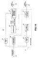
- Fig. 16 shows an application example of the present invention using the aforementioned encoder and decoder.
- This application example employs the conventional SCMS (serial copy management) in combination with analog copy management according to an embodiment of the invention.
- An analog audio input Si inputted from a signal input terminal 51 is converted by an A/D converter 52 into a digital signal.
- the digital signal is supplied via a SW53 to a decoder 54 similar to the aforementioned decoder 11 and 35, for reading a copy control signal recorded by a gap and a spectrum diffusion signal.
- a control signal CNT1 is outputted for controlling a SCMS unit.
- the audio signal which has been converted into a digital signal by the A/D converter 52 is supplied via SW56 to the SCMS unit 57.
- the SCMS unit 57 rewrites the digital signal (actually, a sub code area) into a second generation.
- the aforementioned digital audio signal is supplied to an encoder 58 similar to the aforementioned encoder 1 and 20, where it is controlled by the control signal CNT1 so that a gap and a spectrum diffusion are overlapped on the audio signal and the generation information is also rewritten.
- This result is recorded by a recording apparatus 59 on a recording medium tape, disc, or the like) 59a.
- the audio signal reproduced by this recording apparatus 59 is converted by a D/A converter 60 into an analog audio signal which is outputted from an output terminal 61 as an audio output So.
- the signal is supplied via SW56 to the SCMS unit 57 where the generation is rewritten, and supplied to the encoder 58 where the same information is rewritten on the audio signal.
- control signal CNT2 when the conventional SCMS inhibits copying is combined with the control signal CNT1 when the copying is inhibited in analog, and their disjunction as CNT3 will stop recording operation of the recording apparatus 59.
- this signal is reproduced by the recording apparatus (capable of reproduction) 59, this signal is supplied via SW53 so that the additional information data recorded on the audio data will appear on a display unit 62.
- the gap may be destroyed by a special apparatus. To cope with this, the gap can be repaired even if destroyed.
- a correlation of a high reproductivity is defined between a feature of an audio signal recorded and the gap position.
- an apparatus having this function is used to reproduce an audio signal in which the gap has been destroyed, the previous gap insert position can be restored. If the similar processing prior to the destruction is carried out according to this, it is possible to demodulate the spectrum diffusion signal.
- a function other than the copy protection is realized.
- This function can be used, for example, as follows.
- the embedded data such as the music information, the text, and MIDI is destroyed.
- the user unwilling to carry out an unauthorized act because of the data destruction.
- the function of the additional information provides a copy management function such as SCMS extended to analog, which can also be extended to a sub code such as CD/DAT/MD (mini disc) for a sufficient data rate can be obtained.
- SCMS copy management function
- CD/DAT/MD mini disc
- the function available on the digital sub code data such as a music selection and search is also automatically disabled.
- the digital sub code information is also modified and rewritten, (if the analog data has a higher priority), the same problem is caused by the medium recorded by an apparatus using this protect even when mounted on a conventional apparatus. This makes to lose the convenience of a digital apparatus and effectively prevents the user from removing the analog embedded information through an unauthorized revision.
- the present system utilizes important factors of the music information such as attack, tempo, and level.
- important factors of the music information such as attack, tempo, and level.
- the present invention can also be applied to a ground wave between a broadcasting station and a reception apparatus as well as an audio signal transmission by satellite broadcasting, audio signal transmission by Internet, and an audio signal transmission between computers.
- the present system enables a short-time synchronization and detection required for a copy protect and the like. Moreover, by selective writing using a hearing sense masking, it is possible to overlap on an audio signal a data minimizing deterioration of the audio signal.
- the hardware for detection is a simple one which can be realized at low costs. Moreover, it is possible to additionally write a copy generation information, user code, and the like. Moreover, it is possible to realize more data channels than in the conventional one. Moreover, it is possible to correctly read a data even if the audio signal reproduction speed is varied. Moreover, it is possible to transfer a data with an audio compression such as MPEG/ATRAC/AC-3.
- the present system enables a hybrid method using the gap method in combination, simultaneously realizing a simple method and a high technique method, and can be applied to a wide range of product groups. Moreover, it is possible to extend to analog interface the copy management and the data transmission in the conventional digital interface such as SCMS. Moreover, when an additional information embedded is processed for unauthorized copying, the recording apparatus and the reproduction apparatus are disabled to operate correctly, thus inhibiting unauthorized copying.
Applications Claiming Priority (3)
| Application Number | Priority Date | Filing Date | Title |
|---|---|---|---|
| JP4828397 | 1997-03-03 | ||
| JP04828397A JP3690043B2 (ja) | 1997-03-03 | 1997-03-03 | 音声情報伝送装置及び方法並びに音声情報記録装置 |
| JP48283/97 | 1997-03-03 |
Publications (2)
| Publication Number | Publication Date |
|---|---|
| EP0863631A2 true EP0863631A2 (de) | 1998-09-09 |
| EP0863631A3 EP0863631A3 (de) | 2002-11-20 |
Family
ID=12799120
Family Applications (1)
| Application Number | Title | Priority Date | Filing Date |
|---|---|---|---|
| EP98301491A Withdrawn EP0863631A3 (de) | 1997-03-03 | 1998-02-27 | Tondatenübertragung und Aufzeichnung |
Country Status (5)
| Country | Link |
|---|---|
| US (1) | US6452960B1 (de) |
| EP (1) | EP0863631A3 (de) |
| JP (1) | JP3690043B2 (de) |
| KR (1) | KR19980079791A (de) |
| CN (1) | CN1178403C (de) |
Cited By (4)
| Publication number | Priority date | Publication date | Assignee | Title |
|---|---|---|---|---|
| US7460991B2 (en) | 2000-11-30 | 2008-12-02 | Intrasonics Limited | System and method for shaping a data signal for embedding within an audio signal |
| US7505823B1 (en) | 1999-07-30 | 2009-03-17 | Intrasonics Limited | Acoustic communication system |
| US7796978B2 (en) | 2000-11-30 | 2010-09-14 | Intrasonics S.A.R.L. | Communication system for receiving and transmitting data using an acoustic data channel |
| US8560913B2 (en) | 2008-05-29 | 2013-10-15 | Intrasonics S.A.R.L. | Data embedding system |
Families Citing this family (13)
| Publication number | Priority date | Publication date | Assignee | Title |
|---|---|---|---|---|
| US6747969B1 (en) * | 1999-11-23 | 2004-06-08 | Olaf Hirsch | Transmission gap interference measurement |
| DE19961924A1 (de) * | 1999-12-22 | 2001-07-05 | Philips Corp Intellectual Pty | Mobilfunkempfänger mit integriertem Rundfunkempfänger |
| US8909128B2 (en) * | 2008-04-09 | 2014-12-09 | 3D Radio Llc | Radio device with virtually infinite simultaneous inputs |
| US8699995B2 (en) | 2008-04-09 | 2014-04-15 | 3D Radio Llc | Alternate user interfaces for multi tuner radio device |
| US8706023B2 (en) | 2008-01-04 | 2014-04-22 | 3D Radio Llc | Multi-tuner radio systems and methods |
| CA2742644C (en) | 2001-02-20 | 2016-04-12 | Caron S. Ellis | Multiple radio signal processing and storing method and apparatus |
| US8868023B2 (en) * | 2008-01-04 | 2014-10-21 | 3D Radio Llc | Digital radio systems and methods |
| WO2003061285A2 (en) | 2001-12-24 | 2003-07-24 | Scientific Generics Limited | Captioning system |
| EP1614103B1 (de) * | 2003-04-08 | 2007-05-09 | Koninklijke Philips Electronics N.V. | Aktualisieren eines verborgenen datenkanals |
| US9191639B2 (en) * | 2010-04-12 | 2015-11-17 | Adobe Systems Incorporated | Method and apparatus for generating video descriptions |
| CN102594475B (zh) * | 2011-01-10 | 2015-03-25 | 国家广播电影电视总局广播科学研究院 | 调幅中波紧急广播信息的插入装置及方法 |
| CN102594474B (zh) * | 2011-01-10 | 2016-05-11 | 国家广播电影电视总局广播科学研究院 | 实现调幅中波紧急广播的系统及方法 |
| US9437236B2 (en) * | 2013-11-04 | 2016-09-06 | Michael Hugh Harrington | Encoding data |
Citations (6)
| Publication number | Priority date | Publication date | Assignee | Title |
|---|---|---|---|---|
| DE2333524A1 (de) * | 1973-07-02 | 1975-01-23 | Licentia Gmbh | System zur uebertragung eines ersten und eines zweiten signals, insbesondere zur aufzeichnung eines stereotonsignals |
| EP0135192A2 (de) * | 1983-09-16 | 1985-03-27 | Audicom Corporation | Kodierung von gesendetem Programmaterial |
| US4876617A (en) * | 1986-05-06 | 1989-10-24 | Thorn Emi Plc | Signal identification |
| EP0366381A2 (de) * | 1988-10-25 | 1990-05-02 | THORN EMI plc | Signal-Identifikationssystem |
| US5410541A (en) * | 1992-05-04 | 1995-04-25 | Ivon International, Inc. | System for simultaneous analog and digital communications over an analog channel |
| US5450490A (en) * | 1994-03-31 | 1995-09-12 | The Arbitron Company | Apparatus and methods for including codes in audio signals and decoding |
Family Cites Families (9)
| Publication number | Priority date | Publication date | Assignee | Title |
|---|---|---|---|---|
| US5212551A (en) * | 1989-10-16 | 1993-05-18 | Conanan Virgilio D | Method and apparatus for adaptively superimposing bursts of texts over audio signals and decoder thereof |
| US5319735A (en) * | 1991-12-17 | 1994-06-07 | Bolt Beranek And Newman Inc. | Embedded signalling |
| US5646940A (en) * | 1992-05-04 | 1997-07-08 | Novi International, Inc. | System for simultaneous analog and digital communications over an analog channel |
| SG45250A1 (en) * | 1993-01-04 | 1998-01-16 | Intel Corp | Simultaneous transfer of control information with voice and data over a public switched telephone network line |
| US5404377A (en) * | 1994-04-08 | 1995-04-04 | Moses; Donald W. | Simultaneous transmission of data and audio signals by means of perceptual coding |
| US5724340A (en) * | 1995-02-02 | 1998-03-03 | Unisys Corporation | Apparatus and method for amplitude tracking |
| US5774452A (en) * | 1995-03-14 | 1998-06-30 | Aris Technologies, Inc. | Apparatus and method for encoding and decoding information in audio signals |
| US5822360A (en) * | 1995-09-06 | 1998-10-13 | Solana Technology Development Corporation | Method and apparatus for transporting auxiliary data in audio signals |
| US5915027A (en) * | 1996-11-05 | 1999-06-22 | Nec Research Institute | Digital watermarking |
-
1997
- 1997-03-03 JP JP04828397A patent/JP3690043B2/ja not_active Expired - Fee Related
-
1998
- 1998-02-20 US US09/027,372 patent/US6452960B1/en not_active Expired - Fee Related
- 1998-02-27 EP EP98301491A patent/EP0863631A3/de not_active Withdrawn
- 1998-03-02 KR KR1019980006702A patent/KR19980079791A/ko not_active Application Discontinuation
- 1998-03-03 CN CNB98106969XA patent/CN1178403C/zh not_active Expired - Fee Related
Patent Citations (6)
| Publication number | Priority date | Publication date | Assignee | Title |
|---|---|---|---|---|
| DE2333524A1 (de) * | 1973-07-02 | 1975-01-23 | Licentia Gmbh | System zur uebertragung eines ersten und eines zweiten signals, insbesondere zur aufzeichnung eines stereotonsignals |
| EP0135192A2 (de) * | 1983-09-16 | 1985-03-27 | Audicom Corporation | Kodierung von gesendetem Programmaterial |
| US4876617A (en) * | 1986-05-06 | 1989-10-24 | Thorn Emi Plc | Signal identification |
| EP0366381A2 (de) * | 1988-10-25 | 1990-05-02 | THORN EMI plc | Signal-Identifikationssystem |
| US5410541A (en) * | 1992-05-04 | 1995-04-25 | Ivon International, Inc. | System for simultaneous analog and digital communications over an analog channel |
| US5450490A (en) * | 1994-03-31 | 1995-09-12 | The Arbitron Company | Apparatus and methods for including codes in audio signals and decoding |
Cited By (5)
| Publication number | Priority date | Publication date | Assignee | Title |
|---|---|---|---|---|
| US7505823B1 (en) | 1999-07-30 | 2009-03-17 | Intrasonics Limited | Acoustic communication system |
| US7460991B2 (en) | 2000-11-30 | 2008-12-02 | Intrasonics Limited | System and method for shaping a data signal for embedding within an audio signal |
| US7796978B2 (en) | 2000-11-30 | 2010-09-14 | Intrasonics S.A.R.L. | Communication system for receiving and transmitting data using an acoustic data channel |
| US8185100B2 (en) | 2000-11-30 | 2012-05-22 | Intrasonics S.A.R.L. | Communication system |
| US8560913B2 (en) | 2008-05-29 | 2013-10-15 | Intrasonics S.A.R.L. | Data embedding system |
Also Published As
| Publication number | Publication date |
|---|---|
| CN1192614A (zh) | 1998-09-09 |
| JPH10247890A (ja) | 1998-09-14 |
| KR19980079791A (ko) | 1998-11-25 |
| US6452960B1 (en) | 2002-09-17 |
| CN1178403C (zh) | 2004-12-01 |
| JP3690043B2 (ja) | 2005-08-31 |
| EP0863631A3 (de) | 2002-11-20 |
Similar Documents
| Publication | Publication Date | Title |
|---|---|---|
| US6452960B1 (en) | Audio data transmission apparatus and method, audio data recording apparatus, and audio data recording medium | |
| US6175627B1 (en) | Apparatus and method for embedding and extracting information in analog signals using distributed signal features | |
| US5319735A (en) | Embedded signalling | |
| US5719937A (en) | Multi-media copy management system | |
| CA2191667C (en) | Apparatus and method for synthesizing information signal and reproduction control signal and information signal recording apparatus | |
| EP1002388B1 (de) | Vorrichtung und verfahren für die einbettung und wiedergewinnung von informationen in analogen signalen mit verwendung der verteilten signalmerkmale | |
| US7209565B2 (en) | Decoding of an encoded wideband digital audio signal in a transmission system for transmitting and receiving such signal | |
| US7372375B2 (en) | Signal reproducing method and device, signal recording method and device, and code sequence generating method and device | |
| WO1997037448A2 (en) | Apparatus and method for encoding and decoding supplementary data in analog signals | |
| US20040030900A1 (en) | Undetectable watermarking technique for audio media | |
| JPH11110913A (ja) | 音声情報伝送装置及び方法、並びに音声情報受信装置及び方法、並びに記録媒体 | |
| JP2000156641A (ja) | 付加情報重畳方法、情報信号複製制御方法、情報信号出力装置および情報信号記録装置 | |
| EP1304809B1 (de) | Verfahren und vorrichtung zur kodierung und dekodierung eines digitalen signals, und digitales uebertragungssystem | |
| KR100717251B1 (ko) | 스테레오 신호와 데이터 신호를 보유한 기록매체 | |
| JPH10247361A (ja) | 音声情報伝送装置及び方法並びに音声情報記録装置並びに音声情報記録媒体 | |
| KR19990029337A (ko) | 스펙트럼 확산신호 검출방법 및 장치 | |
| JP3888401B2 (ja) | 情報信号出力装置、情報信号出力方法、情報信号再生装置および情報信号再生方法 | |
| JPH01149259A (ja) | 記録媒体 | |
| WO2002007150A2 (en) | Watermarking technique for audio media | |
| JP2000330579A (ja) | 音楽情報への透かし挿入方法、その装置及びプログラム記録媒体 | |
| JP2004226909A (ja) | 情報付加方法 |
Legal Events
| Date | Code | Title | Description |
|---|---|---|---|
| PUAI | Public reference made under article 153(3) epc to a published international application that has entered the european phase |
Free format text: ORIGINAL CODE: 0009012 |
|
| AK | Designated contracting states |
Kind code of ref document: A2 Designated state(s): AT BE CH DE DK ES FI FR GB GR IE IT LI LU MC NL PT |
|
| AX | Request for extension of the european patent |
Free format text: AL;LT;LV;MK;RO;SI |
|
| PUAL | Search report despatched |
Free format text: ORIGINAL CODE: 0009013 |
|
| AK | Designated contracting states |
Kind code of ref document: A3 Designated state(s): AT BE CH DE DK ES FI FR GB GR IE IT LI LU MC NL PT |
|
| AX | Request for extension of the european patent |
Free format text: AL;LT;LV;MK;RO;SI |
|
| AKX | Designation fees paid | ||
| REG | Reference to a national code |
Ref country code: DE Ref legal event code: 8566 |
|
| STAA | Information on the status of an ep patent application or granted ep patent |
Free format text: STATUS: THE APPLICATION IS DEEMED TO BE WITHDRAWN |
|
| 18D | Application deemed to be withdrawn |
Effective date: 20030521 |