EP0852891B1 - Mounting arrangement for a noise cancelling microphone - Google Patents
Mounting arrangement for a noise cancelling microphone Download PDFInfo
- Publication number
- EP0852891B1 EP0852891B1 EP96900070A EP96900070A EP0852891B1 EP 0852891 B1 EP0852891 B1 EP 0852891B1 EP 96900070 A EP96900070 A EP 96900070A EP 96900070 A EP96900070 A EP 96900070A EP 0852891 B1 EP0852891 B1 EP 0852891B1
- Authority
- EP
- European Patent Office
- Prior art keywords
- cavity
- capsule
- microphone
- ports
- speech terminal
- Prior art date
- Legal status (The legal status is an assumption and is not a legal conclusion. Google has not performed a legal analysis and makes no representation as to the accuracy of the status listed.)
- Expired - Lifetime
Links
Images

Classifications
-
- H—ELECTRICITY
- H04—ELECTRIC COMMUNICATION TECHNIQUE
- H04R—LOUDSPEAKERS, MICROPHONES, GRAMOPHONE PICK-UPS OR LIKE ACOUSTIC ELECTROMECHANICAL TRANSDUCERS; DEAF-AID SETS; PUBLIC ADDRESS SYSTEMS
- H04R1/00—Details of transducers, loudspeakers or microphones
- H04R1/20—Arrangements for obtaining desired frequency or directional characteristics
- H04R1/32—Arrangements for obtaining desired frequency or directional characteristics for obtaining desired directional characteristic only
- H04R1/34—Arrangements for obtaining desired frequency or directional characteristics for obtaining desired directional characteristic only by using a single transducer with sound reflecting, diffracting, directing or guiding means
- H04R1/38—Arrangements for obtaining desired frequency or directional characteristics for obtaining desired directional characteristic only by using a single transducer with sound reflecting, diffracting, directing or guiding means in which sound waves act upon both sides of a diaphragm and incorporating acoustic phase-shifting means, e.g. pressure-gradient microphone
-
- H—ELECTRICITY
- H04—ELECTRIC COMMUNICATION TECHNIQUE
- H04M—TELEPHONIC COMMUNICATION
- H04M1/00—Substation equipment, e.g. for use by subscribers
- H04M1/02—Constructional features of telephone sets
- H04M1/19—Arrangements of transmitters, receivers, or complete sets to prevent eavesdropping, to attenuate local noise or to prevent undesired transmission; Mouthpieces or receivers specially adapted therefor
Definitions
- This invention relates to a noise cancelling microphone for a speech terminal, and more particularly to a higher order microphone mounted within a small terminal such as a handset, portable terminal, or a neckset.
- Modern microphones for use in speech terminals are required to provide improved transmission characteristics.
- Microphones higher than zeroth order are used to provide some immunity to acoustic noise. These microphones can discriminate sounds both by source direction and source proximity.
- Pressure microphones have an omnidirectional directivity pattern, while pressure gradient microphones can have directivity patterns such as cardioid, which are most sensitive to sounds impinging from in front of the microphone, decreasing as the direction approaches the back, or "figure 8", which are most sensitive to sounds impinging from the front and back, and least sensitive to sounds impinging from sides.
- These types of noise canceling microphones need to have access to the sound field in more than one place, requiring two or more ports.
- a first order microphone is made to be sensitive to a combination of the sum of, and difference between the pressure at two ports.
- Second and higher order microphones require three or more ports, and the sensitivity is proportional to a combination of the sum of, and the difference between the pressure at these ports.
- a directional microphone assembly is disclosed in GB,A 2 218 303 (Primo Company Limited).
- the microphone assembly capsule comprises a linear pressure gradient microphone arranged in a casing. Acoustic openings are formed on the front face of the casing.
- Figure 4 illustrates an embodiment where the casing, which has a substantially rectangular section, is divided into two chambers and the microphone is placed with the acoustic main axis "a" parallel to the front surface of the casing.
- Other directional microphone assemblies (capsules) have cylindrical enclosures, with acoustic ports provided on one or both bases.
- such microphone assemblies should operate in a substantially free-field environment in order to have the best noise-canceling effect. This presents a problem in mounting the capsule in a telephone housing due to the increased acoustic impedance presented to the ports, and to diffraction. These effects generally degrade the noise canceling performance of the microphone and alter the frequency response. The following requirements should be taken into consideration to circumvent these effects:
- the microphone ports are often at the front and back, which usually violates requirements 1 and 4.
- Some known architectures use a flap for accommodating the microphone. When port locations are the front and back of the flap, as is usually the case, requirements 1 and 4 are again violated.
- a modular microphone assembly is disclosed in European Patent Application 330,364 (Northern Telecom Limited).
- the microphone assembly is housed in a cavity provided in the body base of a telephone to provide an environment that is isolated from the loudspeaker. Reflective internal surfaces in the cavity alter the directional and frequency response characteristics of the microphone for improving the performance of the arrangement.
- the reflective surfaces of the cavity are inclined at different . angles calculated for obtaining a destructive interference, between the sound field produced by a source disposed ahead of the assembly and a sound source disposed behind the assembly at low frequencies.
- Another object of the present invention is to provide a mounting arrangement for a noise canceling apparatus that is compact in structure and simple in construction so that it can readily be implemented in a standard telephone handset, a wireless terminal, a neckset or the like.
- the invention comprises a microphone for a speech terminal operable in close-talk and hands-free modes, comprising: a microphone capsule having an electro-acoustic transducer and two ports; a housing defining a cavity for accommodating said capsule, said cavity having means for mounting said capsule with its geometrical centre substantially corresponding to the geometrical centre of the cavity for leaving substantially equal free space around each of said ports, said cavity having a first wall facing a first one of said ports and a second wall facing a second one of said ports, said first wall being opposed to said second wall, characterised in that said first and second walls are outwardly inclined at generally equal angles.
- the invention comprises a speech terminal, comprising: a microphone capsule having an electro-acoustic transducer and two ports; a housing with a transmit end and a receive end, said housing defining a cavity for accommodating said capsule, said cavity having means for mounting said capsule with its geometrical centre substantially corresponding to the geometrical centre of the cavity for leaving substantially equal free space around each of said ports, said cavity having a first wall facing a first one of said ports and a second wall facing a second one of said ports, said first wall being opposed to said second wall, characterised in that said speech terminal is operable in close-talk and hands-free modes and said first and second walls are outwardly inclined at generally equal angles.
- the invention comprises a method for mounting a capsule with an electroacoustic transducer into a housing of a speech terminal for operation in close-talk and hands-free modes, comprising the steps of:
- the embedded microphone of the present invention has demonstrable, effective noise reduction characteristics.
- Another advantage of the present invention is that it presents a solution for placement of the microphone that is simple, inexpensive and can be implemented in most types of voice terminals.
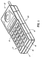
- a telephone handset comprises a housing 10 having a transmit end 11 and a receive end 12 .
- a microphone is placed at the transmit end 11 and a receiver is placed at the receive end 12 .
- the transmit end 11 has openings 17 and 18 , each arranged respectively on face 15 and 16 . It is apparent that mounting the microphone as illustrated in Figure 1, so that one port is on the face plate, and the other is on the end of the terminal, can meet requirement 2, but does not comply with requirements 1 and 4.
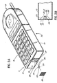
- Figures 2a and 2b illustrate an implementation for a handset according to this invention, where the microphone 22 is embedded with zero profile into a cavity 23 provided in the end face 16 of housing 10 .
- Cavity 23 should be deep enough so that the microphone capsule 22 is fully received therein, while leaving free space in the cavity around the poles of the microphone. While the depth of the cavity is determined mostly by the diameter of the capsule 22 , the distance between each port and the facing cavity wall is determined by the design restrains of the housing and the acoustic impedance of the microphone assembly, as will be discussed later in further detail. In this way, the microphone is practically in an open space. It is not necessary for any of the microphone ports 24 and 25 to actually be visible from the direction of the sound source.
- the invention is particularly effective with microphones which have a front to back symmetry such as the "figure 8" pattern, or dipole microphone. Diffraction and reflection of noise impinging on the side of the microphone (the direction of minimum sensitivity) is symmetric and therefore does not hinder the intrinsic noise canceling ability of the microphone. This meets requirement 1 above.
- the large openings to the spaces above and below the microphone serve to meet requirement 3 above.
- Cavity 23 is selected to have a substantially regular shape, for enabling symmetrical positioning of the microphone inside it.
- the microphone 22 is fixed in the center of the cavity. It is important that the geometrical center of the cavity substantially coincides with the geometrical center of the microphone, for obtaining a high degree of acoustic symmetry (requirement 4) between the front and the back of the microphone.
- Cavity 23 must also allow enough free space around the ports so that the acoustic impedance of the ports is much less than the acoustic impedance of the microphone. If the ports impedance is low, it will only negligibly alter the pressure received at microphone ports 24 and 25 .
- the capsule with microphone 22 is fixed within the cavity 23 with any suitable fixing means.
- the capsule median transversal plane should coincide with a median plane of the cavity.
- the capsule may be fixed with a suitable type of glue along dotted line 27 .
- capsule 22 may be fixed into the cavity 23 using tabs positioned along dotted line 28 .
- the electrical signals obtained with the microphone 22 are carried to the electronics of the receiver through wires 20 which are inserted into the housing through holes 21 .
- Cavity 23 is covered with an acoustically transparent screen 26 , which protects the microphone while allowing the sound waves to enter the cavity and arrive at ports 24 and 25 unobstructed.
- selection of the acoustic design and the place of the cavity should take into account the type and size of the microphone assembly and the architecture of the housing.
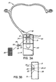
- Figure 3a illustrates the implementation for a neckset.
- a neckset is disclosed and claimed in United States Application No. 08/257,254, filed June 8, 1994.
- the microphone is sufficiently far from the user that some noise cancellation is appropriate.
- the microphone is embedded into the front face 15 of the housing 30, with zero profile, and is covered with a screen 32 .
- the capsule with microphone 22 is fixed within the cavity 31 with any suitable fixing means.
- the capsule median transversal plane should coincide with the median plane of cavity 31 .
- the capsule may be fixed with a suitable glue along dotted line 33 .
- capsule 22 may be fixed into the cavity 31 using tabs positioned along dotted line 28 .
- the quality of the sound is advantageously enhanced by the fact that the body of the wearer obstructs the noise coming from the side opposed to the opening of the cavity.
- Figure 4 shows that the sensitivity in the direction of the user is significantly better than at 45 degrees away, and markedly better still than at 90 degrees away (in the direction of computers, keyboards, other talkers, etc.).
- the mounting arrangement disclosed herein may well be used in other sound transducer schemes and it is not limited to the use in the telephone handsets or necksets.
Landscapes
- Engineering & Computer Science (AREA)
- Signal Processing (AREA)
- Health & Medical Sciences (AREA)
- Otolaryngology (AREA)
- Physics & Mathematics (AREA)
- Acoustics & Sound (AREA)
- Telephone Set Structure (AREA)
- Details Of Audible-Bandwidth Transducers (AREA)
Description
Claims (12)
- A microphone for a speech terminal, operable in close-talk and hands-free modes, comprising: a microphone capsule (22) having an electro-acoustic transducer and two ports (24, 25); a housing (10; 30) defining a cavity (23; 31) for accommodating said capsule (22), said cavity (23; 31) having means for mounting said capsule (22) with its geometrical centre substantially corresponding to the geometrical centre of the cavity (23; 31) for leaving substantially equal free space around each of said ports (24, 25), said cavity (23; 31) having a first wall facing a first one of said ports (24, 25) and a second wall facing a second one of said ports (24, 25), said first wall being opposed to said second wall, characterised in that said first and second walls are outwardly inclined at generally equal angles.
- A microphone as claimed in claim 1, characterised in that the cavity (23; 31) is of a size that leaves sufficient free space around each of the ports (24, 25) such that the microphone capsule operates practically in an open space.
- A microphone as claimed in claim 1 or claim 2, characterised in that the cavity (23; 31) has a depth substantially equal to a transversal size of the capsule (22).
- A microphone as claimed in any one of claims 1 to 3, characterised in that it further comprises an acoustically transparent screen (26; 32) for environmental sealing of said cavity (23; 31).
- A speech terminal, comprising: a microphone capsule (22) having an electro-acoustic transducer and two ports (24, 25); a housing (10; 30) with a transmit end (11) and a receive end (12), said housing defining a cavity (23; 31) for accommodating said capsule (22), said cavity (23; 31) having means for mounting said capsule (22) with its geometrical centre substantially corresponding to the geometrical centre of the cavity (23; 31) for leaving substantially equal free space around each of said ports (24, 25), said cavity (23; 31) having a first wall facing a first one of said ports (24, 25) and a second wall facing a second one of said ports (24, 25), said first wall being opposed to said second wall, characterised in that said speech terminal is operable in close-talk and hands-free modes and said first and second walls are outwardly inclined at generally equal angles.
- A speech terminal as claimed in claim 5, characterised in that the cavity (23; 31) is of a size that leaves sufficient free space around each of the ports (24, 25) such that the microphone capsule operates practically in an open space.
- A speech terminal as claimed in any one of claims 5 or 6, characterised in that the cavity (23; 31) has a depth substantially equal to said transversal size of the capsule (22).
- A speech terminal as claimed in any one of claims 5 to 7, characterised in that the acoustic impedance of each port (24, 25) in the housing (10; 30) of the speech terminal is substantially less than the acoustic impedance of the electroacoustic transducer.
- A speech terminal as claimed in any one of claims 5 to 8, characterised in that it further comprises an acoustically transparent screen (26; 32) for environmental sealing of said capsule (22) in said cavity (23; 31).
- A speech terminal as claimed in any one of claims 5 to 9, characterised in that said electroacoustic transducer is a first or higher order microphone.
- A method for mounting a capsule with an electroacoustic transducer into a housing (10; 30) of a speech terminal operable in close-talk and hands-free modes, comprising the steps of:selecting a capsule (22) with two ports (24, 25), a longitudinal size and a transversal size;providing in said housing (10; 30) a cavity at the transmit end (11) of said speech terminal, said cavity having a first and a second outwardly inclined side walls opposed to each other, and a depth substantially equal to said transversal size of said capsule; andfixing said capsule (22) into said cavity (23; 31) with the geometrical center of said capsule substantially corresponding with the geometrical center of said cavity to leave substantially equal free space around said ports, and with a first port facing said first side wall and a second port facing said second side wall, characterised in that said first and second walls are outwardly inclined at generally equal angles.
- A method as claimed in claim 11, characterised in that said electroacoustic transducer is a first or higher order microphone.
Applications Claiming Priority (3)
| Application Number | Priority Date | Filing Date | Title |
|---|---|---|---|
| US08/535,404 US6421444B1 (en) | 1995-09-28 | 1995-09-28 | Embedded higher order microphone |
| US535404 | 1995-09-28 | ||
| PCT/CA1996/000011 WO1997012495A1 (en) | 1995-09-28 | 1996-01-10 | Mounting arrangement for a noise cancelling microphone |
Publications (2)
| Publication Number | Publication Date |
|---|---|
| EP0852891A1 EP0852891A1 (en) | 1998-07-15 |
| EP0852891B1 true EP0852891B1 (en) | 2001-07-04 |
Family
ID=24134036
Family Applications (1)
| Application Number | Title | Priority Date | Filing Date |
|---|---|---|---|
| EP96900070A Expired - Lifetime EP0852891B1 (en) | 1995-09-28 | 1996-01-10 | Mounting arrangement for a noise cancelling microphone |
Country Status (7)
| Country | Link |
|---|---|
| US (1) | US6421444B1 (en) |
| EP (1) | EP0852891B1 (en) |
| JP (1) | JPH10512419A (en) |
| AU (1) | AU701640B2 (en) |
| CA (1) | CA2228657C (en) |
| DE (1) | DE69613706T2 (en) |
| WO (1) | WO1997012495A1 (en) |
Families Citing this family (9)
| Publication number | Priority date | Publication date | Assignee | Title |
|---|---|---|---|---|
| WO1999002010A1 (en) * | 1997-07-04 | 1999-01-14 | Maxon Systems Inc. (London) Ltd. | Enclosure for a microphone |
| DE19953203A1 (en) | 1999-11-05 | 2007-12-06 | Basf Coatings Ag | Process for the preparation of multicoat color and / or effect paint systems using self-crosslinking graft copolymers of polyurethanes and novel self-crosslinking polyurethanes and their graft copolymers |
| JP3420756B2 (en) * | 2001-10-30 | 2003-06-30 | 株式会社テムコジャパン | Handset for communication equipment |
| TW585375U (en) * | 2002-12-13 | 2004-04-21 | Hon Hai Prec Ind Co Ltd | Microphone housing for handset |
| US7233679B2 (en) * | 2003-09-30 | 2007-06-19 | Motorola, Inc. | Microphone system for a communication device |
| JP5227736B2 (en) * | 2008-10-17 | 2013-07-03 | 三洋電機株式会社 | Recording device |
| US8351634B2 (en) * | 2008-11-26 | 2013-01-08 | Analog Devices, Inc. | Side-ported MEMS microphone assembly |
| US9226052B2 (en) | 2013-01-22 | 2015-12-29 | Invensense, Inc. | Microphone system with non-orthogonally mounted microphone die |
| US9628596B1 (en) | 2016-09-09 | 2017-04-18 | Sorenson Ip Holdings, Llc | Electronic device including a directional microphone |
Family Cites Families (12)
| Publication number | Priority date | Publication date | Assignee | Title |
|---|---|---|---|---|
| US4420657A (en) * | 1981-10-29 | 1983-12-13 | Acs Communications, Inc. | Adjustable headset |
| CA1200308A (en) * | 1983-11-23 | 1986-02-04 | Peter Fatovic | Directional microphone assembly |
| CA1199138A (en) | 1983-11-29 | 1986-01-07 | Peter Fatovic | Telephone handset having close-talking microphone |
| US4742548A (en) | 1984-12-20 | 1988-05-03 | American Telephone And Telegraph Company | Unidirectional second order gradient microphone |
| CA1297578C (en) | 1988-02-26 | 1992-03-17 | Mark Walter Pocock | Modular microphone assembly |
| JP2541621B2 (en) * | 1988-04-20 | 1996-10-09 | 株式会社プリモ | Directional microphone |
| DE3926884A1 (en) * | 1989-08-16 | 1991-02-21 | Neumann Gmbh Georg | ELECTROACOUSTIC CONVERTER |
| US5121426A (en) | 1989-12-22 | 1992-06-09 | At&T Bell Laboratories | Loudspeaking telephone station including directional microphone |
| US5239578A (en) | 1990-05-15 | 1993-08-24 | Plantronics, Inc. | Noise cancelling apparatus for a telephone handset |
| AT395275B (en) | 1990-12-27 | 1992-11-10 | Akg Akustische Kino Geraete | TELEPHONE HAND APPARATUS DESIGNED AS A DIRECTIONAL MICROPHONE |
| US5204907A (en) | 1991-05-28 | 1993-04-20 | Motorola, Inc. | Noise cancelling microphone and boot mounting arrangement |
| US5226076A (en) * | 1993-02-28 | 1993-07-06 | At&T Bell Laboratories | Directional microphone assembly |
-
1995
- 1995-09-28 US US08/535,404 patent/US6421444B1/en not_active Expired - Lifetime
-
1996
- 1996-01-10 EP EP96900070A patent/EP0852891B1/en not_active Expired - Lifetime
- 1996-01-10 CA CA002228657A patent/CA2228657C/en not_active Expired - Fee Related
- 1996-01-10 AU AU43257/96A patent/AU701640B2/en not_active Ceased
- 1996-01-10 WO PCT/CA1996/000011 patent/WO1997012495A1/en active IP Right Grant
- 1996-01-10 JP JP9513018A patent/JPH10512419A/en active Pending
- 1996-01-10 DE DE69613706T patent/DE69613706T2/en not_active Expired - Lifetime
Also Published As
| Publication number | Publication date |
|---|---|
| CA2228657C (en) | 2004-01-06 |
| AU701640B2 (en) | 1999-02-04 |
| DE69613706T2 (en) | 2002-05-08 |
| DE69613706D1 (en) | 2001-08-09 |
| AU4325796A (en) | 1997-04-17 |
| JPH10512419A (en) | 1998-11-24 |
| CA2228657A1 (en) | 1997-04-03 |
| WO1997012495A1 (en) | 1997-04-03 |
| EP0852891A1 (en) | 1998-07-15 |
| US6421444B1 (en) | 2002-07-16 |
Similar Documents
| Publication | Publication Date | Title |
|---|---|---|
| CN113099364B (en) | Electronic device | |
| US9961437B2 (en) | Dome shaped microphone array with circularly distributed microphones | |
| KR100329134B1 (en) | Portable electric device with a speaker assembly | |
| US8428285B2 (en) | Microphone screen with common mode interference reduction | |
| US6633647B1 (en) | Method of custom designing directional responses for a microphone of a portable computer | |
| US7072482B2 (en) | Microphone with improved sound inlet port | |
| US6064894A (en) | Portable radio telephone having improved speaker and housing assembly for handsfree and private operation | |
| EP0985327B1 (en) | Flush mounted uni-directional microphone | |
| JP2609822B2 (en) | Transmitter | |
| US4528426A (en) | Directional microphone assembly | |
| US20050069156A1 (en) | Noise canceling microphone with acoustically tuned ports | |
| US4885773A (en) | Apparatus for mounting a unidirectional microphone in a hands-free telephone subset | |
| EP0595534B1 (en) | Compact loudspeaker assembly for telephone set | |
| JPH08340592A (en) | Gradient microphone assembly that removes noise | |
| EP0852891B1 (en) | Mounting arrangement for a noise cancelling microphone | |
| GB2218303A (en) | Directional microphone | |
| JPH1127356A (en) | Communication equipment especially as telephone set | |
| US6275580B1 (en) | Teleconferencing device having acoustic transducers positioned to improve acoustic echo return loss | |
| JPS62110349A (en) | Transmitter | |
| CN110868669A (en) | Directional microphone | |
| EP1578092A1 (en) | Universal microphone array stand | |
| EP0944220B1 (en) | Audio diaphragm mounting arrangements in radio telephone handsets | |
| CN216356802U (en) | Mobile terminal equipment | |
| JP3567703B2 (en) | Earset handset | |
| JPH03117148A (en) | Loudspeaker telephone set |
Legal Events
| Date | Code | Title | Description |
|---|---|---|---|
| PUAI | Public reference made under article 153(3) epc to a published international application that has entered the european phase |
Free format text: ORIGINAL CODE: 0009012 |
|
| 17P | Request for examination filed |
Effective date: 19980428 |
|
| AK | Designated contracting states |
Kind code of ref document: A1 Designated state(s): DE FR GB |
|
| 17Q | First examination report despatched |
Effective date: 19980805 |
|
| RAP3 | Party data changed (applicant data changed or rights of an application transferred) |
Owner name: NORTEL NETWORKS CORPORATION |
|
| GRAG | Despatch of communication of intention to grant |
Free format text: ORIGINAL CODE: EPIDOS AGRA |
|
| RAP1 | Party data changed (applicant data changed or rights of an application transferred) |
Owner name: NORTEL NETWORKS LIMITED |
|
| GRAG | Despatch of communication of intention to grant |
Free format text: ORIGINAL CODE: EPIDOS AGRA |
|
| GRAG | Despatch of communication of intention to grant |
Free format text: ORIGINAL CODE: EPIDOS AGRA |
|
| GRAH | Despatch of communication of intention to grant a patent |
Free format text: ORIGINAL CODE: EPIDOS IGRA |
|
| GRAH | Despatch of communication of intention to grant a patent |
Free format text: ORIGINAL CODE: EPIDOS IGRA |
|
| GRAA | (expected) grant |
Free format text: ORIGINAL CODE: 0009210 |
|
| AK | Designated contracting states |
Kind code of ref document: B1 Designated state(s): DE FR GB |
|
| REF | Corresponds to: |
Ref document number: 69613706 Country of ref document: DE Date of ref document: 20010809 |
|
| ET | Fr: translation filed | ||
| REG | Reference to a national code |
Ref country code: GB Ref legal event code: IF02 |
|
| PLBE | No opposition filed within time limit |
Free format text: ORIGINAL CODE: 0009261 |
|
| STAA | Information on the status of an ep patent application or granted ep patent |
Free format text: STATUS: NO OPPOSITION FILED WITHIN TIME LIMIT |
|
| 26N | No opposition filed | ||
| PGFP | Annual fee paid to national office [announced via postgrant information from national office to epo] |
Ref country code: GB Payment date: 20141230 Year of fee payment: 20 |
|
| PGFP | Annual fee paid to national office [announced via postgrant information from national office to epo] |
Ref country code: FR Payment date: 20141226 Year of fee payment: 20 |
|
| PGFP | Annual fee paid to national office [announced via postgrant information from national office to epo] |
Ref country code: DE Payment date: 20150126 Year of fee payment: 20 |
|
| REG | Reference to a national code |
Ref country code: DE Ref legal event code: R071 Ref document number: 69613706 Country of ref document: DE |
|
| REG | Reference to a national code |
Ref country code: GB Ref legal event code: PE20 Expiry date: 20160109 |
|
| PG25 | Lapsed in a contracting state [announced via postgrant information from national office to epo] |
Ref country code: GB Free format text: LAPSE BECAUSE OF EXPIRATION OF PROTECTION Effective date: 20160109 |