EP0851699A2 - A mobile communication apparatus with a security function and a method of communicating with a base station with security - Google Patents
A mobile communication apparatus with a security function and a method of communicating with a base station with security Download PDFInfo
- Publication number
- EP0851699A2 EP0851699A2 EP97122640A EP97122640A EP0851699A2 EP 0851699 A2 EP0851699 A2 EP 0851699A2 EP 97122640 A EP97122640 A EP 97122640A EP 97122640 A EP97122640 A EP 97122640A EP 0851699 A2 EP0851699 A2 EP 0851699A2
- Authority
- EP
- European Patent Office
- Prior art keywords
- call
- base station
- detected
- communication apparatus
- sound
- Prior art date
- Legal status (The legal status is an assumption and is not a legal conclusion. Google has not performed a legal analysis and makes no representation as to the accuracy of the status listed.)
- Granted
Links
Images


Classifications
-
- H—ELECTRICITY
- H04—ELECTRIC COMMUNICATION TECHNIQUE
- H04M—TELEPHONIC COMMUNICATION
- H04M1/00—Substation equipment, e.g. for use by subscribers
- H04M1/60—Substation equipment, e.g. for use by subscribers including speech amplifiers
- H04M1/6033—Substation equipment, e.g. for use by subscribers including speech amplifiers for providing handsfree use or a loudspeaker mode in telephone sets
- H04M1/6041—Portable telephones adapted for handsfree use
- H04M1/6075—Portable telephones adapted for handsfree use adapted for handsfree use in a vehicle
-
- H—ELECTRICITY
- H04—ELECTRIC COMMUNICATION TECHNIQUE
- H04W—WIRELESS COMMUNICATION NETWORKS
- H04W88/00—Devices specially adapted for wireless communication networks, e.g. terminals, base stations or access point devices
- H04W88/02—Terminal devices
-
- H—ELECTRICITY
- H04—ELECTRIC COMMUNICATION TECHNIQUE
- H04M—TELEPHONIC COMMUNICATION
- H04M1/00—Substation equipment, e.g. for use by subscribers
- H04M1/66—Substation equipment, e.g. for use by subscribers with means for preventing unauthorised or fraudulent calling
Definitions
- This invention relates to a mobile communication apparatus with a security function and a method of communicating with a base station with security.
- a mobile communication apparatus which can receive a call from a base station and can transmit a call from the base station while it moves.
- a mobile communication apparatus having a paging function is also known.
- the aim of the present invention is to provide an improved mobile communication apparatus and an improved method of communicating with a base station.
- a radio communication apparatus which comprises: a radio wave signal communication circuit for receiving from and transmitting a radio wave signal to a base station; a communication circuit for providing communication to an operator through the radio wave signal receiving and transmission circuit; a speed detecting circuit for detecting a speed of the radio communication apparatus to the base station from an output of the radio wave signal communication circuit; a comparing circuit for comparing the detected speed with a reference; and a control circuit responsive to the comparing circuit for controlling the communication circuit when the detected speed exceeds the reference.
- the speed detecting circuit may comprise: a measuring circuit for measuring an electrostatic field intensity of the received radio wave signal in response to a timing signal; a storing circuit for repeatedly storing recent predetermined sets of output data from the measuring circuit; a variation detection circuit for detecting a variation in the recent predetermined sets of output data to generate a speed signal from the detected variation; and a timing control circuit for generating a timing signal in accordance with the speed signal.
- the communication circuit may further comprise a call detection circuit for detecting a call from the base station via the radio wave signal communication circuit, wherein the control circuit neglects the detected call when the detected speed exceeds the reference.
- the communication circuit may further comprise an operation circuit for receiving a dialing operation to make a call to the base station via the radio wave signal communication circuit, wherein the control circuit inhibits the communication circuit from making the call when the detected speed exceeds the reference.
- the communication circuit may further comprise a sound alarming circuit for generating an alarming sound, wherein the control circuit operates the sound alarming circuit to generate the alarming sound when the detected speed exceeds the reference.
- the sound alarming circuit may further comprise a sound message storing circuit for storing a predetermined sound alarming message data, wherein the control circuit reads and reproduces the predetermined sound alarming message data by the speaker when the detected speed exceeds the reference.
- the communication circuit may further comprise a character data storing circuit for storing a predetermined character alarming message data and a display, wherein the control circuit reads and displays the predetermined character alarming message data on the display when the detected speed exceeds the reference.
- the communication circuit may comprise a message storing circuit for storing message and call detection circuit for detecting a call from the base station and the control circuit reads and transmits the predetermined message to a caller of the call via the base station when the detected speed exceeds the reference.
- the communication circuit may comprise a vibrator for vibrating a housing of the radio communication apparatus, wherein the control circuit operates the vibrator to provide vibrations of the housing to the bearer of radio communication apparatus when the detected speed exceeds the reference.
- the communication circuit may comprise a call detection circuit for detecting a call from the base station and a buzzer for informing the user of the detected call, wherein the control circuit controls a sound intensity of a sound from the buzzer when the detected speed exceeds the reference.
- the communication circuit may comprise a call detection circuit for detecting a call from the base station and automatic answering circuit, having a memory, for transmitting a predetermined out-going message through the radio wave signal communication circuit and recording a message from the base station and the control circuit operates the automatic answering circuit to record the massage from the caller in response to the detected call when the detected speed exceeds the reference.
- the communication circuit may comprise a paging signal detection circuit for detecting a paging signal including a message from the radio wave signal from the base station and storing circuit, wherein the control circuit stores the message in storing circuit when the detected speed exceeds the reference.
- the communication circuit may comprise a call detection circuit for detecting a call from the base station and sound processing circuit including first amplifier for receiving and amplifying a first sound from an operator with a first gain and second amplifier for amplifying a sound signal from the base station with a second gain, wherein the control circuit increases first and second gains to provide a hands-free communication to the operator in response to the detected call when the detected speed exceeds the reference.
- the communication circuit may comprise a call detection circuit for detecting a call from the base station, a storing circuit, a telephone number data detection circuit for detecting telephone number data from the received radio wave signal, and a one-touch dialing circuit having a one-touch dial key, wherein the control circuit operates the telephone number data detection circuit in response to the detected call when the detected speed exceeds the reference and stores the detected telephone number data in the storing circuit and in response to an operation the one-touch dialing key, the control circuit operates the communication circuit to transmit a dialing signal using the telephone number data from the storing circuit.
- the communication circuit may comprise a call detection circuit for detecting a call from the base station, a character data storing circuit for storing character message data, a character data sending circuit for sending the character message data from the character data storing circuit to the base station through the radio wave signal communication circuit, wherein the control circuit reads the character message data and operates the character data sending circuit to send the read character message data to the base station in response to the detected call when the detected speed exceeds the reference.
- the communication circuit may further comprise a call detection circuit for detecting a call from the base station, a sound message storing circuit for storing sound message data, wherein the control circuit reads the sound message data and transmits the read sound message data to base station through the radio wave signal communication circuit in response to the detected call when the detected speed exceeds the reference.
- the speed detecting circuit may comprise a receiving circuit for receiving a vehicle speed signal to detect the speed of the radio communication apparatus.
- a method of communicating with a base station comprising the steps of: (a) receiving from and transmitting a radio wave signal to a base station; (b) providing communication to an operator through the step (a); (c) detecting a speed to the base station from the received radio wave signal; (d) comparing the detected speed with a reference; and (e) effecting controlling regarding the communication when the detected speed exceeds the reference.
- the method may further comprise the steps of: measuring an electrostatic field intensity of the received radio wave signal in response to a timing signal; repeatedly storing recent predetermined sets of output data of the measured electrostatic field intensities; detecting a variation in the recent predetermined sets of output data to generate a speed signal from the detected variation; and generating a timing signal in accordance with the speed signal.
- the method may further comprise the steps of: detecting a call from the base station; and neglecting the detected call when the detected speed exceeds the reference.
- the method may further comprise the steps of: receiving a dialing operation to make a call to the base station; and inhibiting making the call when the detected speed exceeds the reference.
- the method may further comprise the step of: generating an alarming sound when the detected speed exceeds the reference.
- the method may further comprise the step of: storing a predetermined sound alarming message data; and reading and reproducing the predetermined sound alarming message data when the detected speed exceeds the reference.
- the method may further comprise the step of: storing a predetermined character alarming message data; and reading and displaying the predetermined character alarming message data when the detected speed exceeds the reference.
- the method may further comprise the step of: storing a predetermined message; detecting a call from the base station; and reading and transmitting the predetermined message to a caller of the call via the base station when the detected speed exceeds the reference.
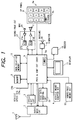
- Fig. 1 is a block diagram of a mobile unit communication apparatus of the embodiment.
- the mobile unit communication apparatus of the first embodiment comprises an antenna 1, a radio wave circuit, a speed detection circuit 3, a processing and a control circuit (DSP) 5, a sound processing circuit 27, a microphone 24, a speaker 7, an operation panel 8, a vibrator 9, a buzzer 10, a display 11, a hands-free mount detection circuit 13, a vehicle mount adapter detection circuit 4, a code signal sending circuit 22, a memory 6, and a non-volatile memory 12.
- DSP processing and a control circuit
- the radio wave circuit 2 receives the radio wave signal including a telephone signal and a paging signal from a base station (not shown) and outputs a baseband reception signal from the received the radio wave signal.
- the processing and control circuit 5 receives the base band reception signal and in response to a call in the base band reception signal operates the vibrator 9 or the buzzer 10 to inform the operator of the arrival of the call and supplies a sound signal to the speaker 7 to reproduce the sound signal for communication through the sound processing circuit 27.
- the microphone 24 receives the sound from the operator and supplies a second sound signal to the processing and control circuit 5 through the sound processing circuit 27.
- the processing and control circuit 5 processes the second sound signal and supplies a base band transmission signal.
- the radio wave circuit 2 transmits the radio wave signal to the base station from the base band transmission signal from the antenna 1.
- the processing and control circuit 5 generates a dialing signal in response to the ten-keys 8a on the operation panel 8 and a one-touch dialing key 8b. That is, when the operator depress the one-touch dialing key 8b, the processing and control circuit 5 generates the dialing signal in accordance with telephone number data in the non-volatile memory 12, which was stored in response to the operation to the operation panel 8.
- the radio wave circuit 2 also transmits the dialing signal through the transmitted radio wave signal.
- the non-volatile memory 12 further stores a safety driving flag which is inputted from the operation panel 8 under control of the processing and control circuit 5, telephone number data, a character alarming character message, a sound alarming message in response to the operation by the operator to the operation panel 8 and the microphone 24 under the control of the processing and control circuit 5.
- the non-volatile memory 12 further stores a paging message and telephone number data included in the telephone signal and the paging signal in response to the paging signal from the base station under the control of the processing and control circuit 5.
- the hands-free mount detector 13 has contacts (not shown) for detecting whether the body of the mobile unit communication apparatus is mounted on a hands-free mount (not shown) and supplies a hands-free mount detection signal to the processing and control circuit 5 when the body of the mobile unit communication apparatus is mounted on the hands-free mount.
- the vehicle mount adapter detector 4 has contacts for detecting whether the body of the mobile unit communication apparatus is mounted on a vehicle mount (not shown) and supplies a vehicle mount detection signal to the processing and control circuit 5 when the body of the mobile unit communication apparatus is mounted on the vehicle mount. Moreover, the vehicle mount adapter has a terminal 23b for supplying a vehicle speed signal 23a to the processing and control circuit 5 if the vehicle speed signal 23a is supplied to the terminal 23b.
- the code signal generating circuit 22 generates baseband code data for sending it through the radio wave circuit 2 from data from the processing and control circuit 5 such as a character message.
- the radio wave circuit also transmits the character code signal as the paging signal.
- Fig. 2 is a block diagram of the speed detection circuit 3 shown in Fig. 1.
- the speed detection circuit 3 comprises a reception electrostatic field intensity measuring circuit 14, a memory 16, a variation detection circuit 17, a memory 19, and a timing control circuit 18.
- the reception electrostatic field intensity measuring circuit 14 measures the reception electrostatic field intensity from the output of the radio wave circuit 2 in response to a timing signal from the timing control circuit 18.
- the memory 16 stores data of the reception electric field intensity. More specifically, the memory 16 repeatedly stores recent predetermined sets of output data from the reception electrostatic field intensity measuring circuit 14.
- the variation detection circuit 17 detects variations in the recent predetermined sets of output data to determine a phasing pitch and generates a speed signal from the detected variation.
- the timing control circuit 18 generates the timing signal in accordance with the speed signal.
- the speed signal is generated by the speed detection circuit 3 by measuring the phasing frequency from the variation in the reception electric field intensity as mentioned.
- it also possible to detect the speed signal from a Doppler shift which occurs between the base station and the mobile unit communication apparatus which relatively moves against the base station.
- Fig. 7 depicts a flow chart of this embodiment showing a main routine executed by the processing and control circuit 5.
- the processing and control circuit 5 receives an input operation in step s3 and s4. That is, the processing and control circuit 5 receives mode-setting for the security such as a call neglecting mode, a sound alarming message mode, a character alarming message mode, an alarming sound mode, transmitting sound and character message modes, an automatic answering mode, a vibrator mode, a paging mode, a receiving character message mode, a telephone number detecting mode, and a line hold mode and stores corresponding flags in the non-volatile memory 12.
- mode-setting for the security such as a call neglecting mode, a sound alarming message mode, a character alarming message mode, an alarming sound mode, transmitting sound and character message modes, an automatic answering mode, a vibrator mode, a paging mode, a receiving character message mode, a telephone number detecting mode, and a line hold mode and stores corresponding flags in the non-volatile memory 12.
- the processing and control circuit 5 receives a decreasing sound level of alarming mode, that is, a manner mode, a sound alarming message mode, a character alarming message mode or the like and stores corresponding flags in the non-volatile memory 12.
- a decreasing sound level of alarming mode that is, a manner mode, a sound alarming message mode, a character alarming message mode or the like.
- the processing and control circuit 5 receives a call in steps s5 and s2 and a calling operation in steps s6 and s1 and returns to step s3.
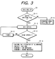
- Fig. 3 depicts a flow chart of this embodiment showing the calling operation s1.
- the processing and control circuit 5 executes a program as shown in Fig. 3 in response to a calling operation by the operator to the operation panel 8.
- the processing and control circuit 5 checks whether the safety driving flag has been set in the non-volatile memory 12 in step s1-1. If the safety driving flag has not been set, the conventional calling operation is executed in step s1-6.
- the processing and control circuit 5 operates the speed signal detection circuit 3 and receives the speed signal in step s1-2.
- the processing and control circuit 5 checks whether the speed signal indicates a high speed by comparing at least a reference. If the speed signal indicates the high speed, the processing and control circuit 5 informs the operator of alarming by the speaker 7, that is a sound alarming message, by the display 11, that is, an alarming character message or flickering a predetermined sign on the display 11, inhibits the actual calling operation, that is, the processing and control circuit 5 neglects the calling demand in step s1-4.
- step s1-4 the processing and control circuit 5 further transmits a character message automatically to the called party determined by the operation to the operation panel 8 if the character message is stored in the non-volatile memory 12 and the corresponding flag has been set in the non-volatile memory 12. Moreover, in step s1-4, the processing and control circuit 5 further transmits a sound message automatically to the called party determined by the operation to the operation panel 8 if the sound message is stored in the non-volatile memory 12 and the corresponding flag has been set.
- step s1-3 if the speed signal does not indicate the high speed, the processing and control circuit 5 operates a timer 5a included therein. When a predetermined interval has passed, processing returns to step s1-2 to detect the speed again and repeats the processing in the loop of the step s1-5, s1-2, s1-3 until the high speed is detected. That is, if the speed of the vehicles increase and reaches the reference high speed, the operations in step s1-4 are executed more surely.
- Fig. 4 depicts a flow chart of this embodiment showing a call arrival operation.
- the processing and control circuit 5 executes a program as shown in Fig. 4 in response to the call from the base station.
- the processing and control circuit 5 checks whether the safety driving flag has been set in the non-volatile memory 12 in step s2-1. If the safety driving flag has not been set, the conventional response operation is executed in step s2-8.
- the processing and control circuit 5 operates the speed signal detection circuit 3 and receives the speed signal in step s2-2.
- the processing and control circuit 5 checks whether the speed signal indicates a high speed by comparing the reference. If the speed signal indicates the high speed, the processing and control circuit 5, the processing and control circuit 5 checks whether there is the hands-free mount detection signal in step s2-4. If there is the hands-free mount detection signal from the hands-free mount detection circuit 13, the processing and control circuit 5 sets the flag of the hands-free mode.
- the hand-free mode is that gains of the amplifier 27a and 27d for the microphone 24 and the receiver 7 are increased. Then, processing proceeds to step s2-5.
- step s2-5 If there is no hands-free mount detection signal, processing directly proceeds to step s2-5.
- step s2-5 the processing and control circuit 5 checks whether there is the vehicle mount adapter detection signal in step s2-5 fro the vehicle mount adapter detection circuit 4. If there is the vehicle mount adapter detection signal, processing proceeds to a processing A, that is, a subroutine s2-9. If there is not the vehicle mount adapter detection signal, processing proceeds to a processing B, that is, a subroutine s2-10.
- Fig. 5 depicts a flow chart of this embodiment showing the processing A s2-9.
- the processing and control circuit 5 checks whether the operator is communicating in step s3-1. If the operator is communicating, the processing and control circuit 5 generates a sound alarming message.
- step s3-3 the processing and control circuit 5 executes all of or some of functions in accordance with the flags which has been set from the operation panel 8 in the non-volatile memory 12.
- the functions are neglecting the call, generating a sound alarming message, displaying a character alarming message, generating an alarming sound, transmitting sound and character messages, effecting automatically answering, operating the vibrator 9, receiving a character message in the paging signal, detecting the telephone number and storing it in the non-volatile memory 12 for one-touch dialing, or holding the line.
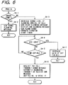
- Fig. 6 depicts a flow chart of this embodiment showing the processing B s2-10.
- step s4-1 the processing and control circuit 5 checks whether the operator is communicating. If the operator is communicating, the processing and control circuit 5 generates the sound alarming message to the operator in step s4-2.
- step s4-3 the processing and control circuit 5 executes all of or some of functions in accordance with the flags which have been set from the operation panel 8 in the non-volatile memory 12.
- the function are operating the sound processing circuit 27 to decrease the sound level of the alarm informing the arrival of the call, generating the sound alarming message to provide the caution, generating the alarm sound, operating the vibrator.
- step s4-3 the processing and control circuit 5 further operates the timer 5a.
- step s4-4 the processing and control circuit 5 checks whether there is a key input. If there is no key input, the processing and control circuit 5 checks the predetermined time interval set in the timer 5a has expired. If the time interval has expired, in step s4-6,the processing and control circuit 5 executes all or some of functions in accordance with the flags in the non-volatile memory 12. The functions are neglecting the call transmits the sound message to the caller, effecting an automatic answering operation, transmitting or receiving a character message through the paging signal, detecting the telephone number and storing it in the non-volatile memory 12 for one-touch dialing.
- step s4-4 if there is a key input, the processing and control circuit 5 increases the gain of the microphone 24 by operating the sound processing circuit 27 to decrease a speech level of the operator in step s4-7.
- step s4-4 if there is no key input, the processing and control circuit 5 executes step s4-4 until the predetermined interval set to the timer 5a expires. If the predetermined interval expired, the processing and control circuit 5 effects all of or some of functions such as neglecting the call, transmitting a sound message, automatic answering, transmitting or receiving character message, and detecting the telephone number of the caller and store it in the non-volatile memory for the one touch dialing in steps s4-6.
- the reference compared with the speed signal is one.
- the speed may be classified such that a high speed, a middle speed, and a low speed.
- the security operations in steps s1-4, s3-3. s4-3. s4-6, s4-7 may be executed in accordance with the plurality of classified speeds.
- a radio communication apparatus which has a radio wave signal communication circuit and a speed detection circuit for detecting a speed of the radio communication apparatus to the base station from an output of the radio wave signal communication circuit.
- Various operations for security such as neglecting arrival of a call when the vehicle carrying the radio communication apparatus is in a high speed condition are selectively executed in accordance with the detected speed signal.
- a method of communicating with a base station with various operations mentioned above is also disclosed.
Abstract
Description
Claims (25)
- A radio communication apparatus comprising:radio wave signal communication means (1, 2) for receiving from and transmitting a radio wave signal to a base station;communication means (5, 7, 9, 10, 11, 12, 24) for providing communication to an operator through said radio wave signal receiving and transmission means;speed detecting means (14-19) for detecting a speed of said radio communication apparatus to said base station from an output of said radio wave signal communication means;comparing means (20) for comparing the detected speed with a reference;
andcontrol means responsive to said comparing means for controlling said communication means when the detected speed exceeds said reference. - The radio communication apparatus as claimed in claim 1, wherein said speed detecting means comprises:measuring means for measuring an electrostatic field intensity of the received radio wave signal in response to a timing signal;storing means for repeatedly storing recent predetermined sets of output data from said measuring means;variation detection means for detecting a variation in said recent predetermined sets of output data to generate a speed signal from the detected variation; andtiming control means for generating a timing signal in accordance with said speed signal.
- The radio communication apparatus as claimed in claim 1, wherein said communication means further comprises call detection means (s2) for detecting a call from said base station via the radio wave signal communication means, wherein said control means neglects the detected call when the detected speed exceeds said reference.
- The radio communication apparatus as claimed in claim 1, said communication means further comprises operation means (8) for receiving a dialing operation to make a call to said base station via the radio wave signal communication means, wherein said control means inhibits said communication means from making said call when the detected speed exceeds said reference.
- The radio communication apparatus as claimed in claim 1, wherein said communication means further comprises sound alarming means (12, 27, 7) for generating an alarming sound, wherein said control means operates said sound alarming means to generate said alarming sound when the detected speed exceeds said reference.
- The radio communication apparatus as claimed in claim 5, wherein said sound alarming means further comprises sound message storing means (12) for storing a predetermined sound alarming message data, wherein said control means reads and reproduces said predetermined sound alarming message data by said speaker when the detected speed exceeds said reference.
- The radio communication apparatus as claimed in claim 1, said communication means further comprises character data storing means (12) for storing a predetermined character alarming message data and a display (11), wherein said control means reads and displays said predetermined character alarming message data on said display when the detected speed exceeds said reference.
- The radio communication apparatus as claimed in claim 1, wherein said communication means comprises message storing means (12) for storing message and call detection means for detecting a call from said base station and said control means reads and transmits said predetermined message to a caller of said call via said base station when the detected speed exceeds said reference.
- The radio communication apparatus as claimed in claim 1, wherein said communication means comprises vibrating means (9) for vibrating a housing of said radio communication apparatus, wherein said control means operates said vibrating means to provide vibrations of said housing to the bearer of radio communication apparatus when the detected speed exceeds said reference.
- The radio communication apparatus as claimed in claim 1, wherein said communication means comprises call detection means for detecting a call from said base station and a buzzer (10) for informing the user of the detected call, wherein said control means controls a sound intensity of a sound from said buzzer when the detected speed exceeds said reference.
- The radio communication apparatus as claimed in claim 1, wherein said communication means comprises call detection means for detecting a call from said base station and automatic answering means (5), having a memory (12), for transmitting a predetermined out-going message through said radio wave signal communication means and recording a message from said base station and said control means operates said automatic answering means to record the massage from the caller in response to the detected call when the detected speed exceeds said reference.
- The radio communication apparatus as claimed in claim 1, wherein said communication means comprises paging signal detection means (5) for detecting a paging signal including a message from said radio wave signal from said base station and storing means (12), wherein said control means stores said message in storing means when the detected speed exceeds said reference.
- The radio communication apparatus as claimed in claim 1, wherein said communication means comprises call detection means for detecting a call from said base station and sound processing means including first amplifying means (27a) for receiving and amplifying a first sound from an operator with a first gain and second amplifying means for amplifying a sound signal from said base station with a second gain, wherein said control means increases first and second gains to provide a hands-free communication to said operator in response to the detected call when the detected speed exceeds said reference.
- The radio communication apparatus as claimed in claim 1, wherein said communication means comprises call detection means for detecting a call from said base station, storing means, telephone number data detection means for detecting telephone number data from the reception radio wave signal, one-touch dialing means having a one-touch dial key, wherein said control means operates said telephone number data detection means in response to the detected call when the detected speed exceeds said reference and stores the detected telephone number data in said storing means and in response to an operation said one-touch dialing key, said control means operates said communication means to transmit a dialing signal using the telephone number data from said storing means.
- The radio communication apparatus as claimed in claim 1, wherein said communication means further comprises call detection means for detecting a call from said base station, character data storing means (12) for storing character message data, character data sending means (22) for sending said character message data from said character data storing means to said base station through said radio wave signal communication means, wherein said control means reads said character message data and operates said character data sending means to send the read character message data to said base station in response to the detected call when the detected speed exceeds said reference.
- The radio communication apparatus as claimed in claim 1, wherein said communication means further comprises call detection means for detecting a call from said base station, sound message storing means (12) for storing sound message data, wherein said control means reads said sound message data and transmits the read sound message data to base station through said radio wave signal communication means in response to the detected call when the detected speed exceeds said reference.
- The radio communication apparatus as claimed in claim 1, wherein said speed detecting means comprises receiving means for receiving a vehicle speed signal to detect said speed of said radio communication apparatus.
- A method of communicating with a base station comprising the steps of:(a) receiving from and transmitting a radio wave signal to a base station;(b) providing communication to an operator through the step (a);(c) detecting a speed to said base station from the received radio wave signal;(d) comparing the detected speed with a reference; and(e) effecting controlling regarding said communication when the detected speed exceeds said reference.
- The method as claimed in claim 18, further comprising the steps of:measuring an electrostatic field intensity of the received radio wave signal in response to a timing signal;repeatedly storing recent predetermined sets of output data from said measuring means;detecting a variation in said recent predetermined sets of output data to generate a speed signal from the detected variation; andgenerating a timing signal in accordance with said speed signal.
- The method as claimed in claim 18, further comprising the steps of:detecting a call from said base station; andneglecting the detected call when the detected speed exceeds said reference.
- The method as claimed in claim 18, further comprising the steps of:receiving a dialing operation to make a call to said base station;inhibiting making said call when the detected speed exceeds said reference.
- The method as claimed in claim 18, further comprising the step of:generating an alarming sound when the detected speed exceeds said reference.
- The method as claimed in claim 18, further comprising the steps of:storing a predetermined sound alarming message data; andreading and reproducing said predetermined sound alarming message data when the detected speed exceeds said reference.
- The method as claimed in claim 18, further comprising the steps of:storing a predetermined character alarming message data; andreading and displaying said predetermined character alarming message data when the detected speed exceeds said reference.
- The method as claimed in claim 18, further comprising the steps of:storing a predetermined message;detecting a call from said base station; andreading and transmitting said predetermined message to a caller of said call via said base station when the detected speed exceeds said reference.
Applications Claiming Priority (3)
| Application Number | Priority Date | Filing Date | Title |
|---|---|---|---|
| JP34730496 | 1996-12-26 | ||
| JP8347304A JPH10190557A (en) | 1996-12-26 | 1996-12-26 | Radio equipment |
| JP347304/96 | 1996-12-26 |
Publications (3)
| Publication Number | Publication Date |
|---|---|
| EP0851699A2 true EP0851699A2 (en) | 1998-07-01 |
| EP0851699A3 EP0851699A3 (en) | 2000-11-08 |
| EP0851699B1 EP0851699B1 (en) | 2002-08-28 |
Family
ID=18389316
Family Applications (1)
| Application Number | Title | Priority Date | Filing Date |
|---|---|---|---|
| EP97122640A Expired - Lifetime EP0851699B1 (en) | 1996-12-26 | 1997-12-22 | A mobile communication apparatus with a security function and a method of communicating with a base station with security |
Country Status (5)
| Country | Link |
|---|---|
| US (1) | US6263190B1 (en) |
| EP (1) | EP0851699B1 (en) |
| JP (1) | JPH10190557A (en) |
| CN (1) | CN1148983C (en) |
| DE (1) | DE69714959T2 (en) |
Cited By (18)
| Publication number | Priority date | Publication date | Assignee | Title |
|---|---|---|---|---|
| EP0899890A2 (en) * | 1997-08-25 | 1999-03-03 | Nec Corporation | Apparatus and method for mobile communications |
| EP1071297A2 (en) * | 1999-07-21 | 2001-01-24 | Nokia Mobile Phones Ltd. | Operational modes determination of a controlled device |
| WO2001010152A1 (en) * | 1999-07-30 | 2001-02-08 | Ericsson Inc. | Automatic message transmission to a remote party |
| WO2001056307A2 (en) * | 2000-01-25 | 2001-08-02 | Transient Wireless Technology, Inc. | Affecting communication if a mobile communication unit is likely to be traveling via a motor vehicle |
| EP1156695A2 (en) * | 2000-05-17 | 2001-11-21 | Nec Corporation | Incoming call blocking system and method for mobile terminal |
| EP1204288A1 (en) * | 2000-06-12 | 2002-05-08 | Mitsubishi Denki Kabushiki Kaisha | Telephone system |
| WO2002074584A1 (en) * | 2001-03-15 | 2002-09-26 | International Business Machines Corporation | An automobile computer control system for limiting the usage of wireless telephones in moving automobiles |
| EP1263146A2 (en) * | 2001-05-28 | 2002-12-04 | Matsushita Electric Industrial Co., Ltd. | In-vehicle communication device and communication control method |
| US6640115B1 (en) | 1998-04-01 | 2003-10-28 | Sharp Kabushiki Kaisha | Radio communication apparatus having speed judging circuitry |
| WO2003106222A1 (en) * | 2002-06-13 | 2003-12-24 | Robert Bosch Gmbh | Method and device for assisting a driver when receiving calls |
| FR2847409A1 (en) * | 2002-11-20 | 2004-05-21 | France Telecom | Mobile telephone usage control system for vehicle e.g. car driver, has control unit to authorize use of telephone when vehicle speed is lower than or equal to threshold, block use of telephone when speed is higher than threshold |
| EP1424840A1 (en) * | 2002-11-27 | 2004-06-02 | Motorola Inc. | System and method of automatically answering calls in a wireless communication device |
| EP1148743A3 (en) * | 2000-04-20 | 2005-05-11 | Matsushita Electric Industrial Co., Ltd. | Vehicle-mounted communication system and device |
| EP1580970A1 (en) * | 2004-03-27 | 2005-09-28 | Avaya Inc | Method and apparatus for incoming call pause notification |
| EP1610572A2 (en) * | 2004-06-24 | 2005-12-28 | LG Electronics Inc. | Call connection in mobile terminal |
| CN100382623C (en) * | 2003-12-26 | 2008-04-16 | 华为技术有限公司 | A base station subsystem and method for implementing reporting of base station environment monitoring information |
| CN100382622C (en) * | 2003-12-04 | 2008-04-16 | 华为技术有限公司 | Method for transforing base station environment monitoring information |
| EP1831704A4 (en) * | 2004-12-23 | 2015-07-15 | Power Survey Llc | Sensor for sensing an electric field |
Families Citing this family (66)
| Publication number | Priority date | Publication date | Assignee | Title |
|---|---|---|---|---|
| JP2000091978A (en) | 1998-09-10 | 2000-03-31 | Nec Corp | Digital cordless telephone set and its high speed transfer recognition method |
| JP2000216610A (en) * | 1998-11-19 | 2000-08-04 | Nec Corp | Method and device for sensing and informing contact of human body with antenna for portable telephone set |
| US6816731B1 (en) | 1999-07-19 | 2004-11-09 | Fujitsu Limited | Mobile station equipment, base station equipment, exchange, and mobile communication system |
| US7257417B1 (en) * | 1999-07-20 | 2007-08-14 | Snaptrack, Inc. | Method for determining a change in a communication signal and using this information to improve SPS signal reception and processing |
| WO2001008328A1 (en) | 1999-07-27 | 2001-02-01 | Mitsubishi Denki Kabushiki Kaisha | Device and system for preventing telephone call |
| JP2001157264A (en) | 1999-11-30 | 2001-06-08 | Nec Corp | Wireless communication terminal and automatic function setting method used for it |
| US6690940B1 (en) | 2000-09-22 | 2004-02-10 | James W. Brown | System for selective prevention of non-emergency use of an electronic device |
| US8301108B2 (en) | 2002-11-04 | 2012-10-30 | Naboulsi Mouhamad A | Safety control system for vehicles |
| US6731925B2 (en) * | 2001-10-24 | 2004-05-04 | Mouhamad Ahmad Naboulsi | Safety control system for vehicles |
| JP4654651B2 (en) | 2004-10-13 | 2011-03-23 | トヨタ自動車株式会社 | In-vehicle hands-free call system |
| JP2006115047A (en) * | 2004-10-13 | 2006-04-27 | Hitachi Communication Technologies Ltd | Radio communications terminal, base station control unit, and in-movement communication alarming method |
| US7253642B2 (en) * | 2004-12-23 | 2007-08-07 | Power Survey Company | Method for sensing an electric field |
| US8270933B2 (en) | 2005-09-26 | 2012-09-18 | Zoomsafer, Inc. | Safety features for portable electronic device |
| US7505784B2 (en) * | 2005-09-26 | 2009-03-17 | Barbera Melvin A | Safety features for portable electronic device |
| US8045976B2 (en) * | 2006-04-04 | 2011-10-25 | Aegis Mobility, Inc. | Mobility call management |
| US7697917B2 (en) * | 2006-08-30 | 2010-04-13 | Sony Ericsson Mobile Communications Ab | Method for safe operation of mobile phone in a car environment |
| US9173163B2 (en) * | 2006-09-05 | 2015-10-27 | Broadcom Corporation | Altering communication interface parameters based upon mobility |
| US8160560B2 (en) * | 2007-03-02 | 2012-04-17 | Aegis Mobility, Inc. | Management of mobile device communication sessions to reduce user distraction |
| US8224353B2 (en) | 2007-09-20 | 2012-07-17 | Aegis Mobility, Inc. | Disseminating targeted location-based content to mobile device users |
| US8892112B2 (en) | 2011-07-21 | 2014-11-18 | At&T Mobility Ii Llc | Selection of a radio access bearer resource based on radio access bearer resource historical information |
| US20090318129A1 (en) * | 2008-04-22 | 2009-12-24 | Alister Watt | Mobile Communication Monitoring System |
| MX2011002443A (en) * | 2008-09-05 | 2012-03-06 | Aegis Mobility Inc | Bypassing enhanced services. |
| US20100148920A1 (en) * | 2008-12-15 | 2010-06-17 | Earl Warren Philmon | Automated presence detector for motor vehicles |
| US8326319B2 (en) | 2009-01-23 | 2012-12-04 | At&T Mobility Ii Llc | Compensation of propagation delays of wireless signals |
| US20100284290A1 (en) * | 2009-04-09 | 2010-11-11 | Aegis Mobility, Inc. | Context based data mediation |
| US9386447B2 (en) | 2009-07-21 | 2016-07-05 | Scott Ferrill Tibbitts | Method and system for controlling a mobile communication device |
| US8761821B2 (en) | 2009-07-21 | 2014-06-24 | Katasi Llc | Method and system for controlling a mobile communication device in a moving vehicle |
| US9615213B2 (en) | 2009-07-21 | 2017-04-04 | Katasi Llc | Method and system for controlling and modifying driving behaviors |
| US20110039572A1 (en) * | 2009-08-12 | 2011-02-17 | Pm&L Concepts, Inc. | Cellular device control |
| US8693977B2 (en) * | 2009-08-13 | 2014-04-08 | Novell, Inc. | Techniques for personal security via mobile devices |
| CN101668078A (en) * | 2009-09-16 | 2010-03-10 | 美商威睿电通公司 | Wireless mobile communication device, chip set and hand-free mode adjusting method |
| US8224349B2 (en) | 2010-02-25 | 2012-07-17 | At&T Mobility Ii Llc | Timed fingerprint locating in wireless networks |
| US9053513B2 (en) | 2010-02-25 | 2015-06-09 | At&T Mobility Ii Llc | Fraud analysis for a location aware transaction |
| US9196157B2 (en) | 2010-02-25 | 2015-11-24 | AT&T Mobolity II LLC | Transportation analytics employing timed fingerprint location information |
| US9008684B2 (en) | 2010-02-25 | 2015-04-14 | At&T Mobility Ii Llc | Sharing timed fingerprint location information |
| US8254959B2 (en) | 2010-02-25 | 2012-08-28 | At&T Mobility Ii Llc | Timed fingerprint locating for idle-state user equipment in wireless networks |
| US8447328B2 (en) | 2010-08-27 | 2013-05-21 | At&T Mobility Ii Llc | Location estimation of a mobile device in a UMTS network |
| US9009629B2 (en) * | 2010-12-01 | 2015-04-14 | At&T Mobility Ii Llc | Motion-based user interface feature subsets |
| US8559932B2 (en) | 2010-12-20 | 2013-10-15 | Ford Global Technologies, Llc | Selective alert processing |
| EP2523434A1 (en) | 2011-05-11 | 2012-11-14 | 10n2 Technologies, Inc. | A method for limiting the use of a mobile communications device dependent on the travelling speed |
| US8559981B2 (en) | 2011-05-31 | 2013-10-15 | Delphi Technologies, Inc. | System and method for controlling communication modes of a personal communication device traveling in a vehicle |
| US8612410B2 (en) | 2011-06-30 | 2013-12-17 | At&T Mobility Ii Llc | Dynamic content selection through timed fingerprint location data |
| US9462497B2 (en) | 2011-07-01 | 2016-10-04 | At&T Mobility Ii Llc | Subscriber data analysis and graphical rendering |
| US8897802B2 (en) | 2011-07-21 | 2014-11-25 | At&T Mobility Ii Llc | Selection of a radio access technology resource based on radio access technology resource historical information |
| US9519043B2 (en) | 2011-07-21 | 2016-12-13 | At&T Mobility Ii Llc | Estimating network based locating error in wireless networks |
| US8761799B2 (en) | 2011-07-21 | 2014-06-24 | At&T Mobility Ii Llc | Location analytics employing timed fingerprint location information |
| US8666390B2 (en) | 2011-08-29 | 2014-03-04 | At&T Mobility Ii Llc | Ticketing mobile call failures based on geolocated event data |
| US8923134B2 (en) | 2011-08-29 | 2014-12-30 | At&T Mobility Ii Llc | Prioritizing network failure tickets using mobile location data |
| US8762048B2 (en) | 2011-10-28 | 2014-06-24 | At&T Mobility Ii Llc | Automatic travel time and routing determinations in a wireless network |
| US8909247B2 (en) | 2011-11-08 | 2014-12-09 | At&T Mobility Ii Llc | Location based sharing of a network access credential |
| US8970432B2 (en) | 2011-11-28 | 2015-03-03 | At&T Mobility Ii Llc | Femtocell calibration for timing based locating systems |
| US9026133B2 (en) | 2011-11-28 | 2015-05-05 | At&T Mobility Ii Llc | Handset agent calibration for timing based locating systems |
| CN102624989A (en) * | 2012-03-30 | 2012-08-01 | 深圳市金立通信设备有限公司 | Automatic detecting system and method for contextual model of smart mobile phone |
| US8925104B2 (en) | 2012-04-13 | 2014-12-30 | At&T Mobility Ii Llc | Event driven permissive sharing of information |
| US8929827B2 (en) | 2012-06-04 | 2015-01-06 | At&T Mobility Ii Llc | Adaptive calibration of measurements for a wireless radio network |
| US9094929B2 (en) | 2012-06-12 | 2015-07-28 | At&T Mobility Ii Llc | Event tagging for mobile networks |
| US9046592B2 (en) | 2012-06-13 | 2015-06-02 | At&T Mobility Ii Llc | Timed fingerprint locating at user equipment |
| US9326263B2 (en) | 2012-06-13 | 2016-04-26 | At&T Mobility Ii Llc | Site location determination using crowd sourced propagation delay and location data |
| US8938258B2 (en) | 2012-06-14 | 2015-01-20 | At&T Mobility Ii Llc | Reference based location information for a wireless network |
| US8897805B2 (en) | 2012-06-15 | 2014-11-25 | At&T Intellectual Property I, L.P. | Geographic redundancy determination for time based location information in a wireless radio network |
| US9408174B2 (en) | 2012-06-19 | 2016-08-02 | At&T Mobility Ii Llc | Facilitation of timed fingerprint mobile device locating |
| US8892054B2 (en) | 2012-07-17 | 2014-11-18 | At&T Mobility Ii Llc | Facilitation of delay error correction in timing-based location systems |
| US9351223B2 (en) | 2012-07-25 | 2016-05-24 | At&T Mobility Ii Llc | Assignment of hierarchical cell structures employing geolocation techniques |
| US9351111B1 (en) | 2015-03-06 | 2016-05-24 | At&T Mobility Ii Llc | Access to mobile location related information |
| US9699301B1 (en) | 2015-05-31 | 2017-07-04 | Emma Michaela Siritzky | Methods, devices and systems supporting driving and studying without distraction |
| US10516972B1 (en) | 2018-06-01 | 2019-12-24 | At&T Intellectual Property I, L.P. | Employing an alternate identifier for subscription access to mobile location information |
Citations (5)
| Publication number | Priority date | Publication date | Assignee | Title |
|---|---|---|---|---|
| JPH04246925A (en) * | 1991-01-31 | 1992-09-02 | Nec Corp | On-vehicle automobile telephone device |
| US5301227A (en) * | 1989-04-17 | 1994-04-05 | Sanyo Electic Co., Ltd. | Automatic dial telephone |
| US5444761A (en) * | 1991-07-01 | 1995-08-22 | Pioneer Electronic Corporation | On-vehicle mobile radio telephone with an answering function |
| JPH0833031A (en) * | 1994-07-20 | 1996-02-02 | Fujitsu Ltd | Moving speed estimating device for mobile communication system |
| JPH08149543A (en) * | 1994-11-15 | 1996-06-07 | Kano Densan Hongkong Yugenkoshi | Radio communication equipment |
Family Cites Families (8)
| Publication number | Priority date | Publication date | Assignee | Title |
|---|---|---|---|---|
| FR2571191B1 (en) * | 1984-10-02 | 1986-12-26 | Renault | RADIOTELEPHONE SYSTEM, PARTICULARLY FOR MOTOR VEHICLE |
| DE4010621C1 (en) * | 1990-04-02 | 1991-07-25 | Blaupunkt-Werke Gmbh, 3200 Hildesheim, De | |
| US5266922A (en) * | 1991-03-21 | 1993-11-30 | Sony Electronics, Inc. | Mobile communication apparatus |
| JPH05130019A (en) * | 1991-11-08 | 1993-05-25 | Hitachi Ltd | Position registration system |
| WO1996019786A1 (en) * | 1994-12-19 | 1996-06-27 | Qualcomm Incorporated | Method and apparatus for displaying messages in vehicular communications systems |
| US5917430A (en) * | 1995-08-28 | 1999-06-29 | The Safety Warning System, L.C. | Radar based highway safety warning system |
| US5918180A (en) * | 1995-12-22 | 1999-06-29 | Dimino; Michael | Telephone operable global tracking system for vehicles |
| US5926756A (en) * | 1996-08-26 | 1999-07-20 | Motorola, Inc. | Method and system for programming a cellular phone |
-
1996
- 1996-12-26 JP JP8347304A patent/JPH10190557A/en active Pending
-
1997
- 1997-12-22 EP EP97122640A patent/EP0851699B1/en not_active Expired - Lifetime
- 1997-12-22 DE DE69714959T patent/DE69714959T2/en not_active Expired - Fee Related
- 1997-12-24 US US08/997,994 patent/US6263190B1/en not_active Expired - Lifetime
- 1997-12-26 CN CNB971263329A patent/CN1148983C/en not_active Expired - Fee Related
Patent Citations (5)
| Publication number | Priority date | Publication date | Assignee | Title |
|---|---|---|---|---|
| US5301227A (en) * | 1989-04-17 | 1994-04-05 | Sanyo Electic Co., Ltd. | Automatic dial telephone |
| JPH04246925A (en) * | 1991-01-31 | 1992-09-02 | Nec Corp | On-vehicle automobile telephone device |
| US5444761A (en) * | 1991-07-01 | 1995-08-22 | Pioneer Electronic Corporation | On-vehicle mobile radio telephone with an answering function |
| JPH0833031A (en) * | 1994-07-20 | 1996-02-02 | Fujitsu Ltd | Moving speed estimating device for mobile communication system |
| JPH08149543A (en) * | 1994-11-15 | 1996-06-07 | Kano Densan Hongkong Yugenkoshi | Radio communication equipment |
Non-Patent Citations (3)
| Title |
|---|
| PATENT ABSTRACTS OF JAPAN vol. 017, no. 019 (E-1306), 13 January 1993 (1993-01-13) & JP 04 246925 A (NEC CORP), 2 September 1992 (1992-09-02) * |
| PATENT ABSTRACTS OF JAPAN vol. 1996, no. 06, 28 June 1996 (1996-06-28) & JP 08 033031 A (FUJITSU LTD;OTHERS: 01), 2 February 1996 (1996-02-02) * |
| PATENT ABSTRACTS OF JAPAN vol. 1999, no. 07, 31 March 1999 (1999-03-31) & JP 08 149543 A (KANO DENSAN HONGKONG YUGENKOSHI), 7 June 1996 (1996-06-07) * |
Cited By (29)
| Publication number | Priority date | Publication date | Assignee | Title |
|---|---|---|---|---|
| US6807435B2 (en) | 1997-08-25 | 2004-10-19 | Nec Corporation | Apparatus and method for mobile communications |
| EP0899890A3 (en) * | 1997-08-25 | 2002-09-18 | Nec Corporation | Apparatus and method for mobile communications |
| EP0899890A2 (en) * | 1997-08-25 | 1999-03-03 | Nec Corporation | Apparatus and method for mobile communications |
| US6640115B1 (en) | 1998-04-01 | 2003-10-28 | Sharp Kabushiki Kaisha | Radio communication apparatus having speed judging circuitry |
| EP1071297A2 (en) * | 1999-07-21 | 2001-01-24 | Nokia Mobile Phones Ltd. | Operational modes determination of a controlled device |
| US7711355B1 (en) | 1999-07-21 | 2010-05-04 | Nokia Mobile Phones, Ltd. | Device used in a vehicle which is controlled by vehicular operation to avoid dangerous vehicular operation |
| EP1071297A3 (en) * | 1999-07-21 | 2002-10-02 | Nokia Corporation | Operational modes determination of a controlled device |
| WO2001010152A1 (en) * | 1999-07-30 | 2001-02-08 | Ericsson Inc. | Automatic message transmission to a remote party |
| WO2001056307A2 (en) * | 2000-01-25 | 2001-08-02 | Transient Wireless Technology, Inc. | Affecting communication if a mobile communication unit is likely to be traveling via a motor vehicle |
| WO2001056307A3 (en) * | 2000-01-25 | 2002-07-18 | Transient Wireless Technology | Affecting communication if a mobile communication unit is likely to be traveling via a motor vehicle |
| EP1148743A3 (en) * | 2000-04-20 | 2005-05-11 | Matsushita Electric Industrial Co., Ltd. | Vehicle-mounted communication system and device |
| EP1156695A2 (en) * | 2000-05-17 | 2001-11-21 | Nec Corporation | Incoming call blocking system and method for mobile terminal |
| EP1156695A3 (en) * | 2000-05-17 | 2002-01-02 | Nec Corporation | Incoming call blocking system and method for mobile terminal |
| EP1204288A1 (en) * | 2000-06-12 | 2002-05-08 | Mitsubishi Denki Kabushiki Kaisha | Telephone system |
| EP1204288A4 (en) * | 2000-06-12 | 2005-05-25 | Mitsubishi Electric Corp | Telephone system |
| WO2002074584A1 (en) * | 2001-03-15 | 2002-09-26 | International Business Machines Corporation | An automobile computer control system for limiting the usage of wireless telephones in moving automobiles |
| CN1296227C (en) * | 2001-03-15 | 2007-01-24 | 国际商业机器公司 | Automobile computer contrl system for limiting usage of wireless telephones in moving automobiles |
| EP1263146A3 (en) * | 2001-05-28 | 2003-10-01 | Matsushita Electric Industrial Co., Ltd. | In-vehicle communication device and communication control method |
| EP1263146A2 (en) * | 2001-05-28 | 2002-12-04 | Matsushita Electric Industrial Co., Ltd. | In-vehicle communication device and communication control method |
| WO2003106222A1 (en) * | 2002-06-13 | 2003-12-24 | Robert Bosch Gmbh | Method and device for assisting a driver when receiving calls |
| FR2847409A1 (en) * | 2002-11-20 | 2004-05-21 | France Telecom | Mobile telephone usage control system for vehicle e.g. car driver, has control unit to authorize use of telephone when vehicle speed is lower than or equal to threshold, block use of telephone when speed is higher than threshold |
| EP1424840A1 (en) * | 2002-11-27 | 2004-06-02 | Motorola Inc. | System and method of automatically answering calls in a wireless communication device |
| CN100382622C (en) * | 2003-12-04 | 2008-04-16 | 华为技术有限公司 | Method for transforing base station environment monitoring information |
| CN100382623C (en) * | 2003-12-26 | 2008-04-16 | 华为技术有限公司 | A base station subsystem and method for implementing reporting of base station environment monitoring information |
| EP1580970A1 (en) * | 2004-03-27 | 2005-09-28 | Avaya Inc | Method and apparatus for incoming call pause notification |
| US8285338B2 (en) | 2004-03-27 | 2012-10-09 | Avaya Inc | Method and apparatus for incoming call pause notification |
| EP1610572A2 (en) * | 2004-06-24 | 2005-12-28 | LG Electronics Inc. | Call connection in mobile terminal |
| EP1610572A3 (en) * | 2004-06-24 | 2006-07-05 | LG Electronics Inc. | Call connection in mobile terminal |
| EP1831704A4 (en) * | 2004-12-23 | 2015-07-15 | Power Survey Llc | Sensor for sensing an electric field |
Also Published As
| Publication number | Publication date |
|---|---|
| CN1148983C (en) | 2004-05-05 |
| JPH10190557A (en) | 1998-07-21 |
| US6263190B1 (en) | 2001-07-17 |
| EP0851699A3 (en) | 2000-11-08 |
| DE69714959D1 (en) | 2002-10-02 |
| EP0851699B1 (en) | 2002-08-28 |
| DE69714959T2 (en) | 2003-04-24 |
| CN1189752A (en) | 1998-08-05 |
Similar Documents
| Publication | Publication Date | Title |
|---|---|---|
| EP0851699A2 (en) | A mobile communication apparatus with a security function and a method of communicating with a base station with security | |
| EP0310379B1 (en) | Radio telephone apparatus | |
| GB2343080A (en) | Headset for mobile phone/radio combination has a device for muting the radio signal when the phone is in use | |
| US5946384A (en) | On hold call waiting display method and apparatus | |
| US6236869B1 (en) | Portable terminal equipment | |
| KR20000042944A (en) | Method for limiting receiving in cellular phone | |
| JPH10154955A (en) | Portable telephone set, base station, and high speed mobile state detection method for the portable telephone set | |
| KR100584362B1 (en) | How to mute reception status in wireless communication terminal | |
| KR19990064393A (en) | Mobile phone with breathalyzer | |
| EP1071262A1 (en) | Telephone device mounted in vehicle | |
| JPH10313484A (en) | Control method of handsfree device | |
| KR20000019623A (en) | Radio telephony terminal equipment for alarming message reception of phasor and method for controlling the same. | |
| US5973614A (en) | Radio paging system using radio selective paging receiver | |
| JP2852199B2 (en) | Wireless terminal | |
| KR20000013794A (en) | Short message service identifying method in telecommunication terminal | |
| KR20000039245A (en) | Method for implementing short rest function in cellular phone | |
| JP2622867B2 (en) | Car phone equipment | |
| JPH11196173A (en) | Communication equipment | |
| JPH1094061A (en) | Radio telephone device | |
| KR20000067593A (en) | Alarm apparatus and method of a cellular phone | |
| KR20000040068A (en) | System and method for controlling sound volume at telephone call by mobile terminal | |
| JPH09247078A (en) | Telephone system for moving machine | |
| JP2001086224A (en) | Radio communication unit | |
| JP2002290545A (en) | On-vehicle hands-free device | |
| KR20020066454A (en) | Hands free system and automatic answering method therefor |
Legal Events
| Date | Code | Title | Description |
|---|---|---|---|
| PUAI | Public reference made under article 153(3) epc to a published international application that has entered the european phase |
Free format text: ORIGINAL CODE: 0009012 |
|
| 17P | Request for examination filed |
Effective date: 19971222 |
|
| AK | Designated contracting states |
Kind code of ref document: A2 Designated state(s): DE FR GB |
|
| AX | Request for extension of the european patent |
Free format text: AL;LT;LV;MK;RO;SI |
|
| PUAL | Search report despatched |
Free format text: ORIGINAL CODE: 0009013 |
|
| AK | Designated contracting states |
Kind code of ref document: A3 Designated state(s): AT BE CH DE DK ES FI FR GB GR IE IT LI LU MC NL PT SE |
|
| AX | Request for extension of the european patent |
Free format text: AL;LT;LV;MK;RO;SI |
|
| 17Q | First examination report despatched |
Effective date: 20010122 |
|
| AKX | Designation fees paid |
Free format text: DE FR GB |
|
| GRAG | Despatch of communication of intention to grant |
Free format text: ORIGINAL CODE: EPIDOS AGRA |
|
| GRAG | Despatch of communication of intention to grant |
Free format text: ORIGINAL CODE: EPIDOS AGRA |
|
| GRAH | Despatch of communication of intention to grant a patent |
Free format text: ORIGINAL CODE: EPIDOS IGRA |
|
| GRAH | Despatch of communication of intention to grant a patent |
Free format text: ORIGINAL CODE: EPIDOS IGRA |
|
| GRAA | (expected) grant |
Free format text: ORIGINAL CODE: 0009210 |
|
| AK | Designated contracting states |
Kind code of ref document: B1 Designated state(s): DE FR GB |
|
| REG | Reference to a national code |
Ref country code: GB Ref legal event code: FG4D |
|
| REF | Corresponds to: |
Ref document number: 69714959 Country of ref document: DE Date of ref document: 20021002 |
|
| ET | Fr: translation filed | ||
| PLBE | No opposition filed within time limit |
Free format text: ORIGINAL CODE: 0009261 |
|
| STAA | Information on the status of an ep patent application or granted ep patent |
Free format text: STATUS: NO OPPOSITION FILED WITHIN TIME LIMIT |
|
| 26N | No opposition filed |
Effective date: 20030530 |
|
| PGFP | Annual fee paid to national office [announced via postgrant information from national office to epo] |
Ref country code: FR Payment date: 20051208 Year of fee payment: 9 |
|
| PGFP | Annual fee paid to national office [announced via postgrant information from national office to epo] |
Ref country code: DE Payment date: 20051215 Year of fee payment: 9 |
|
| PGFP | Annual fee paid to national office [announced via postgrant information from national office to epo] |
Ref country code: GB Payment date: 20051221 Year of fee payment: 9 |
|
| PG25 | Lapsed in a contracting state [announced via postgrant information from national office to epo] |
Ref country code: DE Free format text: LAPSE BECAUSE OF NON-PAYMENT OF DUE FEES Effective date: 20070703 |
|
| GBPC | Gb: european patent ceased through non-payment of renewal fee |
Effective date: 20061222 |
|
| REG | Reference to a national code |
Ref country code: FR Ref legal event code: ST Effective date: 20070831 |
|
| PG25 | Lapsed in a contracting state [announced via postgrant information from national office to epo] |
Ref country code: GB Free format text: LAPSE BECAUSE OF NON-PAYMENT OF DUE FEES Effective date: 20061222 |
|
| PG25 | Lapsed in a contracting state [announced via postgrant information from national office to epo] |
Ref country code: FR Free format text: LAPSE BECAUSE OF NON-PAYMENT OF DUE FEES Effective date: 20070102 |