EP0847145A2 - Spread-spectrum communication method and apparatus - Google Patents
Spread-spectrum communication method and apparatus Download PDFInfo
- Publication number
- EP0847145A2 EP0847145A2 EP19970402877 EP97402877A EP0847145A2 EP 0847145 A2 EP0847145 A2 EP 0847145A2 EP 19970402877 EP19970402877 EP 19970402877 EP 97402877 A EP97402877 A EP 97402877A EP 0847145 A2 EP0847145 A2 EP 0847145A2
- Authority
- EP
- European Patent Office
- Prior art keywords
- data
- period
- adjustment
- communication
- spread spectrum
- Prior art date
- Legal status (The legal status is an assumption and is not a legal conclusion. Google has not performed a legal analysis and makes no representation as to the accuracy of the status listed.)
- Granted
Links
Images


Classifications
-
- H—ELECTRICITY
- H04—ELECTRIC COMMUNICATION TECHNIQUE
- H04W—WIRELESS COMMUNICATION NETWORKS
- H04W56/00—Synchronisation arrangements
- H04W56/0055—Synchronisation arrangements determining timing error of reception due to propagation delay
- H04W56/0065—Synchronisation arrangements determining timing error of reception due to propagation delay using measurement of signal travel time
- H04W56/007—Open loop measurement
- H04W56/0075—Open loop measurement based on arrival time vs. expected arrival time
- H04W56/0085—Open loop measurement based on arrival time vs. expected arrival time detecting a given structure in the signal
-
- H—ELECTRICITY
- H04—ELECTRIC COMMUNICATION TECHNIQUE
- H04J—MULTIPLEX COMMUNICATION
- H04J13/00—Code division multiplex systems
Definitions
- the present invention relates to a spread-spectrum communication method and apparatus.
- Fig. 1 shows an example of a format for a data burst in the above communication method.
- data bursts each include a preamble consisting of a synchronization code (SY), a unique word (UW) and a station-identification code (ID), and data (DA).
- SY synchronization code
- UW unique word
- ID station-identification code
- DA station-identification code
- GT guard time
- a receiving end which receives the data bursts uses the synchronization code in the preamble period to perform reproduction of a carrier, input of automatic gain control (AGC), establishment of clock synchronization, and so forth.
- the receiving end further detects the unique word (UW) and the station-identification code (ID), and when it perceives that the successive data (DA) is desired data addressed to itself, it holds a reproduced carrier, AGC, clock synchronization and so forth until the data terminates, and it demodulates the data.
- UW unique word
- ID station-identification code
- this communication method causes an error in the reference clock frequency between the transmitting and receiving ends.
- the receiving end's clock which has held the established synchronization in the preamble, also has increased synchronization errors with respect to the transmitting end's clock.
- the transmission line is wireless
- communication quality may vary with time, which results in the possibility of the input AGC held in the preamble losing its optimum condition with the lapse of time.
- the maximum time during which data can be transmitted with one data burst is limited by the time during which synchronization precision, AGC precision and so forth can be maintained.
- a spread spectrum communication method comprising the steps of: dividing a communication period for spread spectrum data into a plurality of communication periods; and providing an adjustment period for receiving the spread spectrum data between one data-communication period and another data-communication period.
- the spread spectrum communication method may further comprise the step of synchronizing a spread code in the adjustment period.
- the spread spectrum communication method may further comprise the step of providing the adjustment period prior to the plurality of data-communication periods.
- the spread spectrum communication method may further comprise the step of holding the adjusted setting of the receiving end in the data-communication period.
- the spread spectrum communication method may further comprise the step of holding gain in the data-communication period.
- the spread spectrum communication method may further comprise the step of communicating code-division-multiplexed data in the data-communication period.
- the spectrum communication method further comprising the step of providing the adjustment period prior to the plurality of data-communication periods may still further comprise the steps of establishing the setting of a receiving end in the adjustment period prior to the plurality of data communication periods; and correcting the established setting in the adjustment period between one data-communication period and the next data-communication period.
- the gain for the adjustment in the adjustment period prior to the plurality of data-communication periods is larger than the gain for the adjustment in the adjustment period between the one data-communication period and the next data-communication period.
- an adjusting signal communicated in the adjustment period prior to the plurality of data-communication periods is longer than an adjusting signal communicated in the adjustment period between the one data-communication period and the next data-communication period.
- the spread spectrum communication method further comprising the step of communicating code-division-multiplexed data in the data-communication period may further comprise the step of communicating a signal not multiplexed by code division multiplexing, in the adjustment period.
- a spread spectrum communication apparatus comprising: data communication means for communicating spread spectrum data in a plurality of divided data-communication periods; and adjustment-signal communication means for communicating an adjustment signal for adjusting reception of spread spectrum data between one data-communication period and another communication period.
- the spread spectrum communication apparatus may further comprise adjustment means for establishing the setting of a receiving end in accordance with the adjustment signal prior to the plurality of data-communication periods and correcting the established setting in accordance with the adjustment means between the one data-communication period and the next data-communication period.
- the spread spectrum communication apparatus may further comprise holding means for holding the setting of the receiving end in the data-communication period.
- Fig. 1 is a chart showing details of the format of a data burst according to the related art.
- Fig. 2 is a chart showing a case where a large amount of data is transmitted in the related art.
- Fig. 3 is a chart showing the format of a data burst according to a first embodiment of the present invention.
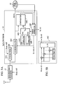
- Figs. 4A and 4B are block diagrams showing a transmitting end in an embodiment of the present invention.
- Figs. 5A and 5B are block diagrams showing a receiving end in an embodiment of the present invention.
- Fig. 6 is a flowchart showing a case where a preamble is being received in the first embodiment of the present invention.
- Fig. 7 is a flowchart showing a case where a mid-amble is being received in the first embodiment of the present invention.
- Fig. 8 is a chart showing the format of data bursts in a second embodiment of the present invention.
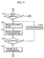
- Fig. 9 is a flowchart showing a case where a mid-amble is being received in the second embodiment of the present invention.
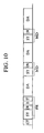
- Fig. 10 is a chart showing the format of data bursts according to a third embodiment of the present invention.
- Fig. 11 is a flowchart showing a case where a preamble is being received in the third embodiment of the present invention.
- Fig. 12 is a flowchart showing a case where a mid-amble is being received in the third embodiment of the present invention.
- Fig. 13 is a chart showing the format of data bursts according to a fourth embodiment of the present invention.
- Fig. 3 shows the format of a data burst according to a first embodiment of a digital communication method of the present invention.
- the data burst having a train-type data-burst structure includes a preamble (PR), data (DA) and one or a plurality of what will, hereinafter, be termed "mid-ambles" (MD).
- the preamble (PR) includes a synchronization code (SY), a unique word representing the start of received data, and a station-identification code (ID) showing which station the information is addressed to.
- the mid-amble (MD) includes a synchronization code (SY).
- the length of the data (DA) is equal to the maximum duration of data capable of being transmitted with one data burst, which is limited by a time during which synchronous precision or AGC precision in the related art can be maintained.
- Figs. 4A, 4B, 5A and 5B show the diagrams of a transmitting end and a receiving end according to the first embodiment of the present invention.
- a data processor 41 in the transmitting end generates a data burst as shown in Fig. 3 in accordance with a command from an upper layer 40, and sends the data burst as a spread spectrum signal to a transmission line via a high-frequency processor 42.
- Information data (DA), a station-identification code (ID), a status indicator (ST) (shown in Fig. 10) and so forth are sent as data from the upper layer 40 into the data processor 41 shown in Fig. 4A.
- an SS modulator 41E outputs the synchronization code (SY) without modulating it in the synchronization-code (SY) period.
- a selector 41D selects a transmission signal from a signal series "0101" generated from a UW generator 41C in accordance with the timing generated by the timing generator 41A.
- the SS modulator 41E performs the spread modulation of the output of the selector 41D, and the modulated output is sent as a spread spectrum signal to the transmission line via the high-frequency processor 42.
- the selector 41D operates so that the SS modulator 41E is not supplied with the signals from the upper layer 40 and the UW generator 41C.
- the timing generator 41A has control such that the synchronization code (SY) is output from the SS modulator 41E in the SY period, the unique word (UW) is output from the UW generator 41C in the unique-word (UW) period among the other periods, and the station-identification code (ID), the status (ST) and the data (DA) are output from the upper layer 40.
- SY synchronization code
- UW unique word
- ID station-identification code
- ST status
- DA data
- Figs. 6 and 7 show flowcharts of the operation of the receiving end when it has received the above-described data burst.
- Fig. 6 shows a condition in which the preamble (PR) is being received
- Fig. 7 shows a condition in which the mid-amble (MD) is being received.
- the receiving end When the receiving end, having received the spread-spectrum data burst, receives the synchronization code (SY) of the preamble (PR) in step S11, the AGC is acquired by a high-frequency processor 43 in steps S12 and S13, and clock synchronization is established by a synchronizer 44A in accordance with the synchronization code in steps S14 and S15.
- the unique word (UW) is detected by a comparator 44E in steps S18 and S19.
- a selector 44G selects a UW generator 44D.
- step S20 When the comparator 44E detects the unique word (UW), in step S20 a timing generator 44F holds the AGC and the clock synchronization by the high-frequency processor 43 and the synchronizer 44A, and switches the selector 44G to an ID generator 44B in step S21.
- step S21 the comparator 44E detects the station-identification code (ID), and when it recognizes that the received data is desired data addressed to the receiving end (i.e., to this particular receiver), the timing generator 44F causes a demodulator 44C to demodulate the data (DA) in step S215.
- ID station-identification code
- Termination of the data (DA) in step S22 is followed by determination of whether or not the next group of data (DA) is being received in step S31. If the next data (DA) is being received (or has arrived in its entirely), reception of the synchronization code (SY) of the mid-amble (MD) causes the timing generator 44F to perform fine adjustment of the AGC by the high-frequency processor 43 in step S32, fine phase adjustment of the clock signal by the synchronizer 44A in step S33, and so forth. An upper layer 45 informs the timing generator 44F whether the data has terminated or whether a following mid-amble has been received, in step S31.
- the clock synchronization in the mid-amble (MD) period is sufficiently achieved by only phase correction, and the initial acquisition of the AGC is not needed. Accordingly, the synchronization code in the mid-amble (MD) period may be shorter than the synchronization code in preamble (PR) period.
- the high-frequency processor 43 increases the gain to cause the rapid acquisition of the AGC in step S13, and decreases the gain to perform fine adjustment of the AGC in step S16 or S32.
- the timing generator 44F holds the AGC and the clock synchronization by the high-frequency processor 43 and the synchronization unit 44 in step S36, and causes an SS demodulator 44C to demodulate the data (DA) in step S215.
- the receiving end performs the above processes until the train terminates.
- the data can be transmitted without separating it into a plurality of data bursts.
- UW unique words
- ID station-identification codes
- GT guard times
- Fig. 8 shows the format of a data burst according to a second embodiment of the present invention.
- the data burst according to the second embodiment has a train-type data-burst structure including a preamble (PR), data (DA) and one or a plurality of mid-ambles (MD).
- the preamble (PR) includes a synchronization code (SY), a unique word (UW) and a station-identification code (ID).
- Each mid-amble includes a synchronization code (SY) and a unique word (UW).
- Fig. 9 shows a flowchart of the operation of the receiving end in handling such a data burst, and in particular, the mid-amble (MD).
- the operation of the receiving end while receiving the preamble (PR) is identical to that shown in Fig. 6.
- the high-frequency processor 43 performs fine adjustment of AGC in step S32 and the synchronizer 44A performs fine phase adjustment of the clock signal and so forth in step S33.
- the clock synchronization in the mid-amble (MD) period is sufficiently achieved by only phase correction, and the initial acquisition of the AGC is not necessary. Accordingly, the synchronization code in the mid-amble (MD) period may be shorter than the synchronization code in the preamble (PR) period.
- the unique word (UW) is detected by the comparator 44E in steps S34A and S35A.
- the timing generator 44F switches the selector 44G to the UW generator 44D.
- the comparator 44E detects the unique word (UW)
- the timing generator 44F holds the AGC and the clock synchronization by the high-frequency processor 43 and the synchronization unit 44 in step S36, and causes the SS demodulator 44C to demodulate the data in step S215.
- Fig. 10 shows the format of a data burst according to a third embodiment of the present invention.
- the data burst has a train type data-burst structure including data (DA) as information to be originally sent, a guard time (GT) provided before the start of sending in order to avoid conflict, a preamble (PR), and one or a plurality of mid-ambles (MD) in data transmission.
- DA data
- GT guard time
- PR preamble
- MD mid-ambles
- the preamble (PR) includes a synchronization code (SY), a unique word (UW) as a signal series of "0101" representing the start of received data, station-identification code (ID) showing which station the information is addressed to, and a status indicator (ST) as information about the length of the data, the type of data and the number of data groups included in one train (three groups of data in Fig. 10).
- the mid-amble (MD) includes a synchronization code (SY) and a unique word (UW).
- the structure described in the third embodiment is identical to those shown in Figs. 4A, 4B, 5A and 5B.
- the receiving end which received the data burst causes the data processor 44 to establish synchronization by means of the high-frequency processor 43 shown in Fig. 5A and to demodulate the data.
- a demodulation clock signal with synchronization established in the synchronization code (SY) period is used to perform reverse spread demodulation in the SS demodulator 44C, and the comparator 44E compares the signal series of "0101" generated from the UW generator 44D and the demodulated data.
- the timing generator 44F If the output data of the SS demodulator 44C coincides with the unique word (UW) from the UW generator 44D, the timing generator 44F generates each predetermined timing included in the data burst, and sends the information data (DA), the station-identification code (ID), the status (ST) and so forth to the upper layer 45.
- Figs. 11 and 12 show flowcharts of the operation of the receiving end when processing the above-described data burst.
- the timing generator 44F sets the selector 44G to the UW generator 44D.
- the AGC is acquired by the high-frequency processor 43 and the clock synchronization is established by the synchronizer 44A in accordance with the synchronization code.
- the timing generator 44F performs setting so that in step S54 the high-frequency processor 43 and the synchronizer 44A hold the AGC and the clock synchronization.
- the timing generator 44F also sets the selector 44G to the ID generator 44B.
- the comparator 44E detects that the station-identification code (ID) received in step S57 is addressed to the receiving end (i.e., to this particular receiver)
- the timing generator 44F recognizes the status input from the SS demodulator 44C in the subsequent step S58.
- the SS demodulator 44C demodulates the data in step S59, and performs setting so that the demodulated data is output to the upper layer 45 until it detects the end of the data in step S60.
- the timing generator 44F controls the reception sequence, based on them.
- notification of the end of the data and the end of the train may be given from the upper layer 45.
- step S61 If in step S61 the end of the train is not detected, or when a mid-amble (MD) and data group (DA) are received after reception of a preceding data group (DA), the previously established AGC and synchronization held in steps S52 and S54 are adjusted in step S71 in accordance with the synchronization code (SY) of the mid-amble (MD).
- step S72 the unique word (UW) of the mid-amble (MD) is detected in step S72, the AGC, the synchronization and so forth are held in step S73, the process returns to step S59.
- the SS demodulator 44C detects the end of the train, the process returns to step S52. Also, if it is found in step S57 that the station-identification code (ID) detected by the SS demodulator 44C is not addressed to the receiving end, the process returns to step S52.
- ID station-identification code
- the acquisition of the clock synchronization and the AGC has been established in the preamble period.
- the clock synchronization in the mid-amble period is sufficiently achieved by only phase correction, and the need for the initial acquisition of the AGC is eliminated.
- the synchronization code (SY) in the mid-amble (MD) may be shorter than the synchronization code (SY) in the preamble (PR) period.
- the high-frequency processor 43 increases the gain in step S52 so that the AGC is rapidly acquired, and in step S71 the gain is reduced to precisely adjust the AGC.
- the synchronizer 44A increases the acquisition gain in step S52, and decreases it in step S71.
- Fig. 13 shows the format of a data burst according to a fourth embodiment of the present invention.
- the data burst shown in Fig. 13 includes a preamble (PR), data groups (DA) and one or a plurality of mid-ambles (MD).
- the preamble (PR) includes a synchronization code (SY), a unique word (UW), and a station-identification code (ID).
- the data (DA) is multiplexed by code division multiplexing.
- Each mid-amble (MD) includes a synchronization code (SY).
- a CDM communication method which is one spread-spectrum communication method used to improve data throughput, uses N mutually orthogonal codes to perform the frequency-axially spread multiplexing of data, and sends the multiplexed data.
- the SS modulator 41E has a structure as shown in Fig. 4B, and performs the code division multiplexing (CDM) of the data burst by using the spread-spectrum (SS) communication method.
- CDM code division multiplexing
- the SS modulator 44C has a structure as shown in Fig. 5B, and uses N mutually orthogonal PN codes to perform the CDM reverse spreading of the code-division-multiplexed data.
- the structures shown in SS modulators 41E and 44C are well known in themselves and need not be described; nonetheless, some details are noted below)
- power consumed by the preamble and the mid-amble can be increased N times power per data channel, which means that synchronization establishing and AGC inputting, need not be greatly affected by a change in the communication quality of the transmission line.
- the spread spectrum modulation and multiplexing (CDM) of the selector 41E output is performed using N mutually orthogonal PN (pseudo-noise) codes.
- the modulator 41E selects a synchronization code PN 0 from spread codes PN 0 to PN n , and outputs it as an SY code to the high-frequency processor 42, without performing the code division multiplexing of it.
- the code-synchronous CDM communication method is a spread-spectrum communication method used to improve the data throughput, which uses N mutually orthogonal codes to perform the spread multiplexing of data onto a frequency, and sends the multiplexed data.
- N mutually orthogonal codes to perform the spread multiplexing of data onto a frequency
- the station-identification code (ID), the status (ST) and the unique word (UW) other than information data are transmitted using one spread code.
Landscapes
- Engineering & Computer Science (AREA)
- Computer Networks & Wireless Communication (AREA)
- Signal Processing (AREA)
- Synchronisation In Digital Transmission Systems (AREA)
- Time-Division Multiplex Systems (AREA)
- Mobile Radio Communication Systems (AREA)
Abstract
Description
Claims (20)
- A spread spectrum communication method comprising the steps of communicating spread spectrum data, and providing an adjustment period for receiving the spread spectrum data, characterized in that:said communication step (S215 or S59) divides a communication period for the spread spectrum data into a plurality of communication periods; andsaid provision step (S32, S33 or S71) provides the adjustment period between one data communication period and another data communication period.
- A spread spectrum communication method according to claim 1, further comprising the step (S33 or S71) of synchronizing a spread code in the adjustment period.
- A spread spectrum communication method according to either one of claims 1 or 2, further comprising the step (S13, S15, S16, S17 or S52) of providing a first adjustment period prior to the plurality of data communication periods.
- A spread spectrum communication method according to claim 3, further comprising:the step (S13, S15, S16, S17 or S52) of establishing the setting of a receiving end in the first adjustment period prior to the plurality of data communication periods; andthe step (S32, S33 or S71) of correcting the setting established in the first adjustment period, between the one data communication period and the other data communication period.
- A spread spectrum communication method according to either one of claims 3 or 4, wherein gain for adjustment in the first adjustment period prior to the plurality of data communication periods is larger than gain for adjustment in the adjustment between the one data communication period and the other communication period.
- A spread spectrum communication method according to any one of claims 3 to 5, wherein an adjustment signal commmunicated in the first adjustment period prior to the plurality of data communication periods is longer than an adjustment signal communicated in the adjustment period between the one data communication period and the other communication period.
- A spread spectrum communication method according to any one of claims 1 to 6, further comprising the step (S36 or S73) of holding the adjusted setting of a receiving end during the data communication period.
- A spread spectrum communication method according to any one of claims 1 to 7, further comprising the step (S32 or S71) of adjusting gain in the adjustment period.
- A spread spectrum communication method according to any one of claims 1 to 8, wherein the communication step communicates code-division-multiplexed data during the data communication period.
- A spread spectrum communication method according to claim 9 further comprising the step of communicating a signal not multiplexed by code division multiplexing during the adjustment period.
- A spread spectrum communication apparatus comprising:data communication means for communicating spread-spectrum data, and adjustment-signal communication means for an adjustment signal for adjusting reception of the spread-spectrum data, characterized in that:said data communication means (41D, 41E, 44C) communicates the spread-spectrum data in a plurality of divided periods, andsaid adjustment-signal communication means (41E, 44A) communicates the adjustment signal for adjusting reception of the spread-spectrum data between one data communication period and another data communication period.
- A spread spectrum communication apparatus according to claim 11, wherein the adjustment signal is a signal for adjusting the synchronization of a spread code.
- A spread spectrum communication apparatus according to either one of claims 11 or 12, wherein said adjustment-signal communication means communicates a first adjustment signal prior to the plurality of data communication periods.
- A spread spectrum communication apparatus according to claim 13, further comprising adjustment means (44A) for establishing the setting of a receiving end in accordance with the first adjustment signal prior to the plurality of data communication periods, and correcting the established setting in accordance with the adjustment signal between the one communication period and the other communication period.
- A spread spectrum communication apparatus according to any one of claims 11 to 14, further comprising holding means (43, 44A) for holding characteristics of a receiving end during the data communication period.
- A spread spectrum communication apparatus according to either one of claims 13 to 15, wherein gain caused by adjustment in accordance with the first adjustment signal prior to the plurality of data communication periods is larger than gain caused by adjustment in accordance with the adjustment signal between the one data communication period and the other data communication period.
- A spread spectrum communication apparatus according to any one of claims 13 to 16, wherein the first adjustment signal prior to the plurality of data communication periods is longer than the adjustment signal between the one data communication period and the other data communication period.
- A spread spectrum communication apparatus according to any one of claims 11 to 17, wherein the adjustment signal is a gain control signal.
- A spread spectrum communication apparatus according to any one of claims 11 to 18, wherein said data communication means communicates code-division-multiplexed data during the data communication period.
- A spread spectrum communication apparatus according to claim 19, wherein said adjustment-signal communication means communicates the adjustment signal not multiplexed by code division multiplexing.
Applications Claiming Priority (3)
| Application Number | Priority Date | Filing Date | Title |
|---|---|---|---|
| JP32271396A JP3305217B2 (en) | 1996-12-03 | 1996-12-03 | Communication method |
| JP32271396 | 1996-12-03 | ||
| JP322713/96 | 1996-12-03 |
Publications (3)
| Publication Number | Publication Date |
|---|---|
| EP0847145A2 true EP0847145A2 (en) | 1998-06-10 |
| EP0847145A3 EP0847145A3 (en) | 2003-06-11 |
| EP0847145B1 EP0847145B1 (en) | 2007-03-07 |
Family
ID=18146798
Family Applications (1)
| Application Number | Title | Priority Date | Filing Date |
|---|---|---|---|
| EP19970402877 Expired - Lifetime EP0847145B1 (en) | 1996-12-03 | 1997-11-28 | Spread-spectrum communication method and apparatus |
Country Status (4)
| Country | Link |
|---|---|
| US (2) | US6285666B1 (en) |
| EP (1) | EP0847145B1 (en) |
| JP (1) | JP3305217B2 (en) |
| DE (1) | DE69737437T2 (en) |
Cited By (2)
| Publication number | Priority date | Publication date | Assignee | Title |
|---|---|---|---|---|
| WO2000036806A1 (en) * | 1998-12-15 | 2000-06-22 | Telefonaktiebolaget Lm Ericsson (Publ) | Method and arrangement in a distributed system |
| WO2001059950A1 (en) * | 2000-02-08 | 2001-08-16 | Tantivy Communications, Inc. | Access channel structure for wireless communication system |
Families Citing this family (11)
| Publication number | Priority date | Publication date | Assignee | Title |
|---|---|---|---|---|
| JP3305217B2 (en) * | 1996-12-03 | 2002-07-22 | キヤノン株式会社 | Communication method |
| JP3120792B2 (en) | 1998-09-11 | 2000-12-25 | 日本電気株式会社 | Spread spectrum communication method and spread spectrum communication apparatus |
| EP1414170B1 (en) * | 2000-03-20 | 2008-11-26 | Mitsubishi Electric Information Technology Centre Europe B.V. | Base station for transmitting a word representative of spreading codes respectively allocated to the mobile stations in communication with the base station |
| DE60040934D1 (en) * | 2000-04-04 | 2009-01-08 | Mitsubishi Electric Inf Tech | A base station for transmitting a word representative of the number of spreading codes allocated to the mobile stations in communication with the base station |
| FR2830997B1 (en) * | 2001-10-12 | 2004-02-13 | Thomson Licensing Sa | GAIN CONTROL METHOD FOR GUSTED SIGNAL RECEIVER AND RECEIVER USING THE SAME |
| CN100438640C (en) * | 2002-12-30 | 2008-11-26 | Nxp股份有限公司 | Sampling method and its device for down synchronous tracking in TDD radio communication |
| JP2006004964A (en) * | 2004-06-15 | 2006-01-05 | Nec Electronics Corp | Aligner and exposure method |
| US7953191B2 (en) * | 2005-12-28 | 2011-05-31 | Thomson Licensing | Gain control method and device for a bursty data frame reception system |
| JP4858373B2 (en) * | 2007-09-12 | 2012-01-18 | 住友電気工業株式会社 | Gain adjustment circuit and radio communication apparatus |
| JP2009207035A (en) | 2008-02-29 | 2009-09-10 | Oki Electric Ind Co Ltd | Code division multiplex communication system |
| JP4966329B2 (en) * | 2009-03-19 | 2012-07-04 | 株式会社東芝 | Wireless receiver power consumption control method |
Citations (9)
| Publication number | Priority date | Publication date | Assignee | Title |
|---|---|---|---|---|
| US4247945A (en) * | 1979-10-22 | 1981-01-27 | Bell Telephone Laboratories, Incorporated | Extraction of data characters imbedded in data bytes |
| US5163070A (en) * | 1990-12-07 | 1992-11-10 | Datatape Incorporated | Digital data synchronizer |
| EP0603788A2 (en) * | 1992-12-24 | 1994-06-29 | Matsushita Electric Industrial Co., Ltd. | Receiving apparatus for a spread spectrum signal |
| EP0605188A2 (en) * | 1992-12-30 | 1994-07-06 | Nokia Mobile Phones Ltd. | Symbol and frame synchronization for a TDMA system |
| DE4329317A1 (en) * | 1993-08-31 | 1995-03-02 | Siemens Ag | Method and system for transmitting data |
| EP0652680A2 (en) * | 1993-11-01 | 1995-05-10 | Telefonaktiebolaget Lm Ericsson | Method for communicating in a wireless communication system |
| EP0676908A2 (en) * | 1994-04-08 | 1995-10-11 | Oki Electric Industry Co., Ltd. | Hand-over method for mobile communication |
| EP0726658A2 (en) * | 1995-02-10 | 1996-08-14 | Nokia Mobile Phones Ltd. | Symbol and frame synchronization in both a TDMA system and a CDMA system |
| JPH08237169A (en) * | 1995-02-24 | 1996-09-13 | Hitachi Ltd | Preamble synchronization system |
Family Cites Families (19)
| Publication number | Priority date | Publication date | Assignee | Title |
|---|---|---|---|---|
| DK163699C (en) * | 1986-02-11 | 1992-08-17 | Poul Richter Joergensen | PROCEDURE FOR AUTOMATIC AMPLIFIER CONTROL OF A SIGNAL AND A CIRCUIT FOR EXERCISING THE PROCEDURE |
| JP2624964B2 (en) | 1987-06-09 | 1997-06-25 | キヤノン株式会社 | Wireless communication device |
| US5260969A (en) | 1988-11-14 | 1993-11-09 | Canon Kabushiki Kaisha | Spectrum diffusion communication receiving apparatus |
| US5668803A (en) * | 1989-06-29 | 1997-09-16 | Symbol Technologies, Inc. | Protocol for packet data communication system |
| US5596599A (en) | 1992-12-04 | 1997-01-21 | Canon Kabushiki Kaisha | Spread spectrum receiving apparatus |
| JPH06338873A (en) | 1993-05-28 | 1994-12-06 | Canon Inc | Code division multiple communication device |
| JPH07177126A (en) | 1993-12-20 | 1995-07-14 | Canon Inc | Multiplex communication equipment |
| JPH07240702A (en) | 1994-03-01 | 1995-09-12 | Canon Inc | Spread spectrum communication equipment |
| JP3192047B2 (en) | 1994-06-03 | 2001-07-23 | キヤノン株式会社 | Spread spectrum receiver |
| JP3215018B2 (en) * | 1994-09-09 | 2001-10-02 | 三菱電機株式会社 | Mobile communication system |
| JP3581448B2 (en) * | 1994-10-21 | 2004-10-27 | キヤノン株式会社 | Spread spectrum communication equipment |
| US5917850A (en) * | 1994-11-24 | 1999-06-29 | Canon Kabushiki Kaisha | Spread spectrum receiving apparatus |
| JP3151119B2 (en) | 1995-03-27 | 2001-04-03 | シャープ株式会社 | Parallel spread spectrum communication system |
| US5875218A (en) * | 1995-03-31 | 1999-02-23 | Unisys Corporation | Variable rate clock for timing recovery and method therefor |
| JP3242287B2 (en) | 1995-04-27 | 2001-12-25 | 株式会社日立製作所 | Wireless communication system and communication device |
| US5974106A (en) * | 1995-09-01 | 1999-10-26 | Motorola, Inc. | Method and apparatus for multirate data communications |
| JP2800797B2 (en) * | 1996-08-12 | 1998-09-21 | 日本電気株式会社 | Spread spectrum communication system |
| US7035232B1 (en) * | 1996-12-03 | 2006-04-25 | Canon Kabushiki Kaisha | Spread-spectrum communication method and apparatus |
| JP3305217B2 (en) * | 1996-12-03 | 2002-07-22 | キヤノン株式会社 | Communication method |
-
1996
- 1996-12-03 JP JP32271396A patent/JP3305217B2/en not_active Expired - Fee Related
-
1997
- 1997-11-20 US US08/974,964 patent/US6285666B1/en not_active Expired - Lifetime
- 1997-11-28 EP EP19970402877 patent/EP0847145B1/en not_active Expired - Lifetime
- 1997-11-28 DE DE1997637437 patent/DE69737437T2/en not_active Expired - Lifetime
-
2005
- 2005-06-15 US US11/152,060 patent/US7706317B2/en not_active Expired - Fee Related
Patent Citations (9)
| Publication number | Priority date | Publication date | Assignee | Title |
|---|---|---|---|---|
| US4247945A (en) * | 1979-10-22 | 1981-01-27 | Bell Telephone Laboratories, Incorporated | Extraction of data characters imbedded in data bytes |
| US5163070A (en) * | 1990-12-07 | 1992-11-10 | Datatape Incorporated | Digital data synchronizer |
| EP0603788A2 (en) * | 1992-12-24 | 1994-06-29 | Matsushita Electric Industrial Co., Ltd. | Receiving apparatus for a spread spectrum signal |
| EP0605188A2 (en) * | 1992-12-30 | 1994-07-06 | Nokia Mobile Phones Ltd. | Symbol and frame synchronization for a TDMA system |
| DE4329317A1 (en) * | 1993-08-31 | 1995-03-02 | Siemens Ag | Method and system for transmitting data |
| EP0652680A2 (en) * | 1993-11-01 | 1995-05-10 | Telefonaktiebolaget Lm Ericsson | Method for communicating in a wireless communication system |
| EP0676908A2 (en) * | 1994-04-08 | 1995-10-11 | Oki Electric Industry Co., Ltd. | Hand-over method for mobile communication |
| EP0726658A2 (en) * | 1995-02-10 | 1996-08-14 | Nokia Mobile Phones Ltd. | Symbol and frame synchronization in both a TDMA system and a CDMA system |
| JPH08237169A (en) * | 1995-02-24 | 1996-09-13 | Hitachi Ltd | Preamble synchronization system |
Non-Patent Citations (2)
| Title |
|---|
| BLANZ J ET AL: "Realistic simulations of CDMA mobile radio systems using joint detection and coherent receiver antenna diversity" SPREAD SPECTRUM TECHNIQUES AND APPLICATIONS, 1994. IEEE ISSSTA '94., IEEE THIRD INTERNATIONAL SYMPOSIUM ON OULU, FINLAND 4-6 JULY 1994, NEW YORK, NY, USA,IEEE, 4 July 1994 (1994-07-04), pages 193-197, XP010129693 ISBN: 0-7803-1750-5 * |
| YOW-JONG LIU ET AL: "A SOFT-OUTPUT BIDIRECTIONAL DECISION FEEDBACK EQUALIZATION TECHNIQUE FOR TDMA CELLULAR RADIO" IEEE JOURNAL ON SELECTED AREAS IN COMMUNICATIONS, IEEE INC. NEW YORK, US, vol. 11, no. 7, 1 September 1993 (1993-09-01), pages 1034-1045, XP000400013 ISSN: 0733-8716 * |
Cited By (8)
| Publication number | Priority date | Publication date | Assignee | Title |
|---|---|---|---|---|
| WO2000036806A1 (en) * | 1998-12-15 | 2000-06-22 | Telefonaktiebolaget Lm Ericsson (Publ) | Method and arrangement in a distributed system |
| US7099865B1 (en) | 1998-12-15 | 2006-08-29 | Telefonaktiebolaget Lm Ericsson (Publ) | Method and arrangement in a distributed system |
| WO2001059950A1 (en) * | 2000-02-08 | 2001-08-16 | Tantivy Communications, Inc. | Access channel structure for wireless communication system |
| US6904079B2 (en) | 2000-02-08 | 2005-06-07 | Ipr Licensing, Inc. | Access channel structure for wireless communication system |
| KR100758566B1 (en) * | 2000-02-08 | 2007-09-14 | 아이피알 라이센싱, 인코포레이티드 | Access channel structure for wireless communication system |
| US7483473B2 (en) | 2000-02-08 | 2009-01-27 | Ipr Licensing, Inc. | Access channel structure for wireless communication system |
| US8958457B2 (en) | 2000-02-08 | 2015-02-17 | Ipr Licensing, Inc. | Channel structure for a wireless communication system |
| US9780930B2 (en) | 2000-02-08 | 2017-10-03 | Ipr Licensing, Inc. | Communicating reference and data information in a wireless network |
Also Published As
| Publication number | Publication date |
|---|---|
| DE69737437D1 (en) | 2007-04-19 |
| JPH10163995A (en) | 1998-06-19 |
| DE69737437T2 (en) | 2007-11-29 |
| US6285666B1 (en) | 2001-09-04 |
| JP3305217B2 (en) | 2002-07-22 |
| US7706317B2 (en) | 2010-04-27 |
| EP0847145B1 (en) | 2007-03-07 |
| EP0847145A3 (en) | 2003-06-11 |
| US20050232339A1 (en) | 2005-10-20 |
Similar Documents
| Publication | Publication Date | Title |
|---|---|---|
| US7706317B2 (en) | Spread-spectrum communication method and apparatus | |
| RU2122290C1 (en) | Method and base station for time matching of received signals in communication system with multiple-station access and code channel separation, user set | |
| US5430760A (en) | Random access in mobile radio telephone systems | |
| US5268933A (en) | Data packet alignment in a communication system | |
| US5020056A (en) | Reduction of synchronous fading effects by time hopping of user slots in TDMA frames | |
| EP2161865B1 (en) | A mobile voice communication station for use in a code division multiple access communication system | |
| EP0639899B2 (en) | Random access communication method by use of cdma, and system for mobile stations which use the method | |
| AU663588B2 (en) | TDMA for mobile access in a CDMA system | |
| US6134233A (en) | Apparatus and method of frame aligning information in a wireless telecommunications system | |
| US5809093A (en) | Apparatus and method of frame aligning information in a wireless telecommunications system | |
| CA2137386C (en) | Time division multiple access mobile wireless telecommunication system | |
| EP0851641A2 (en) | Communication method and receiving apparatus for OFDM systems | |
| KR100355727B1 (en) | Method and Device for Frequency Hopping Communication by Changing a Carrier Frequency | |
| EP0564937B1 (en) | CDMA Radio communication system with pilot signal transmission between base station and handsets for channel distortion compensation | |
| WO1997020402A1 (en) | Signal acquisition via repeated access probe transmission | |
| EP0991204B1 (en) | A transmission power control method using a pilot symbol pattern | |
| WO2001067620A2 (en) | Uplink synchronization signal transmission in tdd systems | |
| US7035232B1 (en) | Spread-spectrum communication method and apparatus | |
| CA2268280A1 (en) | Improved synchronization of a receiver with a transmitter using nonlinear transformation metrics | |
| JPH10322309A (en) | Communication equipment | |
| AU711434B2 (en) | Transmission burst for discontinuous transmission | |
| US6324208B1 (en) | Apparatus and method of controlling transmitting power in a subscriber of a wireless telecommunications system | |
| KR100703286B1 (en) | Method for generating phase modulation sequence in a mobile communication thereof phase modulation device | |
| JPH1118067A (en) | Digital data burst transmitting method for image data communication | |
| CN1194759A (en) | Connection establishment method and radio system |
Legal Events
| Date | Code | Title | Description |
|---|---|---|---|
| PUAI | Public reference made under article 153(3) epc to a published international application that has entered the european phase |
Free format text: ORIGINAL CODE: 0009012 |
|
| AK | Designated contracting states |
Kind code of ref document: A2 Designated state(s): AT BE CH DE DK ES FI FR GB GR IE IT LI LU MC NL PT SE |
|
| AX | Request for extension of the european patent |
Free format text: AL;LT;LV;MK;RO;SI |
|
| PUAL | Search report despatched |
Free format text: ORIGINAL CODE: 0009013 |
|
| AK | Designated contracting states |
Designated state(s): AT BE CH DE DK ES FI FR GB GR IE IT LI LU MC NL PT SE |
|
| AX | Request for extension of the european patent |
Extension state: AL LT LV MK RO SI |
|
| RIC1 | Information provided on ipc code assigned before grant |
Ipc: 7H 04B 7/26 B Ipc: 7H 04L 7/04 B Ipc: 7H 04B 1/707 A |
|
| 17P | Request for examination filed |
Effective date: 20031031 |
|
| 17Q | First examination report despatched |
Effective date: 20031203 |
|
| AKX | Designation fees paid |
Designated state(s): DE FR GB |
|
| GRAP | Despatch of communication of intention to grant a patent |
Free format text: ORIGINAL CODE: EPIDOSNIGR1 |
|
| GRAS | Grant fee paid |
Free format text: ORIGINAL CODE: EPIDOSNIGR3 |
|
| GRAA | (expected) grant |
Free format text: ORIGINAL CODE: 0009210 |
|
| AK | Designated contracting states |
Kind code of ref document: B1 Designated state(s): DE FR GB |
|
| REG | Reference to a national code |
Ref country code: GB Ref legal event code: FG4D |
|
| REF | Corresponds to: |
Ref document number: 69737437 Country of ref document: DE Date of ref document: 20070419 Kind code of ref document: P |
|
| PLBE | No opposition filed within time limit |
Free format text: ORIGINAL CODE: 0009261 |
|
| STAA | Information on the status of an ep patent application or granted ep patent |
Free format text: STATUS: NO OPPOSITION FILED WITHIN TIME LIMIT |
|
| 26N | No opposition filed |
Effective date: 20071210 |
|
| PGFP | Annual fee paid to national office [announced via postgrant information from national office to epo] |
Ref country code: DE Payment date: 20141130 Year of fee payment: 18 Ref country code: GB Payment date: 20141124 Year of fee payment: 18 |
|
| PGFP | Annual fee paid to national office [announced via postgrant information from national office to epo] |
Ref country code: FR Payment date: 20141126 Year of fee payment: 18 |
|
| REG | Reference to a national code |
Ref country code: DE Ref legal event code: R119 Ref document number: 69737437 Country of ref document: DE |
|
| GBPC | Gb: european patent ceased through non-payment of renewal fee |
Effective date: 20151128 |
|
| REG | Reference to a national code |
Ref country code: FR Ref legal event code: ST Effective date: 20160729 |
|
| PG25 | Lapsed in a contracting state [announced via postgrant information from national office to epo] |
Ref country code: GB Free format text: LAPSE BECAUSE OF NON-PAYMENT OF DUE FEES Effective date: 20151128 Ref country code: DE Free format text: LAPSE BECAUSE OF NON-PAYMENT OF DUE FEES Effective date: 20160601 |
|
| PG25 | Lapsed in a contracting state [announced via postgrant information from national office to epo] |
Ref country code: FR Free format text: LAPSE BECAUSE OF NON-PAYMENT OF DUE FEES Effective date: 20151130 |