Cross-Reference To Related Applications
This application is a continuation-in-part of co-pending U.S. patent application
Serial No. 07/951,731, filed September 25, 1992, and entitled "Coin Handling
System," which is in turn a continuation-in-part of spending U.S. patent application
Serial No. 07/904,161 filed August 21, 1992, and entitled "Coin Sorter with
Automatic Bag-Switching or Stopping," which in turn is a continuation of U.S. patent
application Serial No. 07/524,134 filed May 14, 1990 (now issued as U.S. patent
number 5,141,443), and entitled "Coin Sorter With Automatic Bag-Switching Or
Stopping."
Field Of The Invention
The present invention relates generally to coin handling systems and, more
particularly, to coin sorter of the type which use a resilient disc rotating
beneath a stationary coin-manipulating head.
Background Of The Invention
A successful coin handling system typically includes at least three factors.
These factors include the accuracy at which the coin denominations are distinguished
during the coin-sorting process, the speed at which the coins are sorted, and the
ability to control the discharge of the sorted coins for purposes of counting and
bagging. Improving the quality of these factors has been an ongoing objective among
designers attempting to improve coin handling systems. Unfortunately, improving the
quality of any one of these factors will generally result in a degradation of the quality
of one of the other factors.
For example, increasing the speed at which the coins are sorted has proven to
be inversely related to the quality of controlling the discharge of the sorted coins.
Typically, improving the speed at which coins are sorted requires increasing the
rotational speed of the rotating disc beneath the stationary head, and controlling the
discharge of the sorted coins requires a high-speed mechanical reaction (e.g.,
blocking the discharge path) and/or suddenly slowing or stopping the rotation of the
rotating disc. By increasing the coin-sorting speed, it is that much more difficult to
react mechanically and/or to stop the rotation of the rotating disc in timely manner.
Improving the accuracy at which the coin denominations are distinguished
during the coin-sorting process has typically required a complete re-tooling of the
stationary coin-manipulating head, which is labor intensive and expensive.
Moreover, each of these stationary-heads provides a coin-discrimination technique
which is acceptably accurate for most commercial applications and only slight
improvements in accuracy are obtained by the costly investments involved in
redesigning stationary-heads.
Accordingly, there is a need for an improved coin sorting system which
increases both the speed at which the coins are sorted and the ability to control the
discharge of the sorted coins and, at the same time, maintaining the accuracy at
which the coin denominations are distinguished during the coin-sorting process,
wherein the coins may be further separated with respect to validity and/or for
discharging into two or more batches.
Summary of the Invention
The coin sorting system and technique
uses essentially a known disc-type stationary-head design and controlls the
associated rotating disc according to the position of the coins on the disc. The
manner in which the disc is controlled significantly increases both the speed at which
the coins are sorted and the ability to control the discharge of the sorted coins.
Because a known disc-type stationary-head design is used, the accuracy at which the
coin denominations are distinguished during the coin-sorting process is maintained.
The coin handling system
reliably terminates the discharge of coins after only a prescribed number of coins of a
prescribed denomination have been discharged, so that no extra coins of that
denomination are discharged. The coin
handling system avoids the need to retrieve discharged coins in excess of a
prescribed number.
An advantage of the invention is that it provides a coin handling system
which permits coins to be sorted at previously unrealized speeds, while providing the
ability to interrupt the discharge of sorted coins virtually instantly.
Another important advantage of this invention is that it provides such an
improved coin handling system which is inexpensive to manufacture.
The present invention provides an improved coin sorter and sorting technique by
diverting coins from their moving direction to discharge them into two or more batches
and/or separating coins with respect to validity.
One implementation of the present invention is a coin sorter with the features of claim
1 comprising in particular a shunting mechanism for separating coins into two or more
batches, which coins are discharged from exit channels of a sorting head.
Another embodiment of the present invention provides a coin sorter with the features
of claim 2, according to which it is discriminated between valid and invalid coins.
Furthermore, in a method of counting and sorting coins of mixed denominations in a
coin sorter according to claim 11 of the invention, a coin sensor/discriminator is used
to discriminate between valid and invalid coins while the coins are carried on a
rotatable disc.
The system of this invention can be used in coin sorters or coin loaders (e.g.,
for loading wrapping machines) to control the automatic stopping of coin discharge
when a prescribed number of coins have been discharged, to prevent the discharge of
undesired excess coins.
Another embodiment of the present invention involves programming a
controller to operate the sorting system according to the type of coin mixture in the
sorting system. In response to one of a plurality of different operating modes being
selected by the user, the controller samples the coins to educate itself as to the
percent of each coin denomination. For example, if the controller senses an
excessive number invalid coins in the system, the sorting speed is decreased to
increase the sorting accuracy. If the controller senses a high percentage of coins of a
particular denomination, the controller can increase the sorting speed for this
particular denomination until a more normal coin mix is sensed.
The above summary of the present invention is not intended to represent each
embodiment, or every aspect, of the present invention. This is the purpose of the
detailed description which follows.
Brief Description Of The Drawing
Other objects and advantages of the invention will become apparent upon
reading the following detailed description and upon reference to the drawings in
which:
Whale the invention is susceptible to various modifications and alternative
forms, certain specific embodiments thereof have been shown by way of example in
the drawings and will be described in detail. It should be understood, however, that
the intention is not to limit the invention to the particular forms described. On the
contrary, the intention is to cover all modifications, equivalents, and alternatives
falling within the spirit and scope of the invention as defined by the appended claims.
Description Of The Preferred Embodiments
Turning now to the drawings and referring first to FIG. 1, a hopper 10
receives coins of mixed denominations and feeds them through central openings in an
annular sorting head or guide plate 12. As the coins pass through these openings,
they are deposited on the top surface of a rotatable disc 13. This disc 13 is mounted
for rotation on a stub shaft (not shown) and driven by an electric motor 14. The disc
13 comprises a resilient pad 16, preferably made of a resilient rubber or polymeric
material, bonded to the top surface of a solid metal disc 17.
As the disc 13 is mated, the coins deposited on the top surface thereof tend to
slide outwardly over the surface of the pad due to centrifugal force. As the coins
move outwardly, those coins which are lying flat on the pad enter the gap between
the pad surface and the guide plate 12 because the underside of the inner periphery of
this plate is spaced above the pad 16 by a distance which is about the same as the
thickness of the thickest coin.
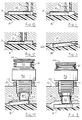
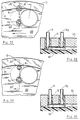
As can be seen most clearly in FIG. 2, the outwardly moving coins initially
enter an annular recess 20 formed in the underside of the guide plate 12 and
extending around a major portion of the inner periphery of the annular guide plate.
The outer wall 21 of the recess 20 extends downwardly to the lowermost surface 22
of the guide plate (see FIG. 3), which is spaced from the top surface of the pad 16 by
a distance which is slightly less, e.g., 0.010 inch, than the thickness of the thinnest
coins. Consequently, the initial radial movement of the coins is terminated when
they engage the wall 21 of the recess 20, though the coins continue to move
circumferentially along the wall 21 by the rotational movement of the pad 16.
Overlapping coins which only partially enter the recess 20 are stripped apart by a
notch 20a formed in the top surface of the recess 20 along its inner edge (see FIG.
4).
The only portion of the central opening of the guide plate 12 which does not
open directly into the recess 20 is that sector of the periphery which is occupied by a
land 23 whose lower surface is at the same elevation as the lowermost surface 22 of
the guide plate. The upstream end of the land 23 forms a ramp 23a (FIG. 5), which
prevents certain coins stacked on top of each other from reaching the ramp 24.
When two or more coins are stacked on top of each other, they may be pressed into
the resilient pad 16 even within the deep peripheral recess 20. Consequently, stacked
coins can be located at different radial positions within the channel 20 as they
approach the land 23. When such a pair of stacked coins has only partally entered
the recess 20, they engage the ramp 23a on the leading edge of the lid 23. The
ramp 23a presses the stacked coins downwardly into the resilient pad 16, which
retards the lower coin while the upper coin continues to be advanced. Thus, the
sacked coins are stripped apart so that they can be recycled and once again enter the
recess 20, this time in a single layer.
When a stacked pair of coins has moved out into the recess 20 before reaching
the land 23, the stacked coins engage the inner spiral wall 26. The vertical
dimension of the wall 26 is slightly less than the thickness of the thinnest coin, so the
lower coin in a stacked pair passes beneath the wall and is recycled while the upper
coin in the stacked pair is cammed outwardly along the wall 26 (see FIGS. 6 and 7).
Thus, the two coins are stripped apart with the upper coin moving along the guide
wall 26, while the lower coin is recycled.
As coins within the recess 20 approach the land 23, those coins move
outwardly around the land 23 and engage a ramp 24 leading into a recess 25 which is
an outward extension of the inner peripheral recess 20. The recess 25 is preferably
just slightly wider than the diameter of the coin denomination having the greatest
diameter. The top surface of the major portion of the recess 25 is spaced away from
the top of the pad 16 by a distance that is less than the thickness of the thinnest coin
so that the coins are gripped between the guide plate 12 and the resilient pad 16 as
they are rotated through the recess 25. Thus, coins which move into the recess 25
are all rotated into engagement with the outwardly spiralling inner wall 26, and then
continue to move outwardly through the recess 25 with the inner edges of all the
coins riding along the spiral wall 26.
As can be seen in FIGS. 6-8, a narrow band 25a of the top surface of the
recess 25 adjacent its inner wall 26 is spaced away from the pad 16 by approximately
the thickness of the thinnest coin. This ensures that coins of all denominations (but
only the upper coin in a stacked or shingled pair) are securely engaged by the wall 26
as it spirals outwardly. The rest of the top surface of the recess 25 tapers
downwardly from the band 25a to the outer edge of the recess 25. This taper causes
the coins to be tilted slightly as they move through the recess 25, as can be seen in
FIGS. 6-8, thereby further ensuring continuous engagement of the coins with the
outwardly spiraling wall 26.
The primary purpose of the outward spiral formed by the wall 26 is to space
apart the coins so that during normal steady-state operation of the sorter, successive
coins will not be touching each other. As will be discussed below, this spacing of
the coins contributes to a high degree of reliability in the counting of the coins.
Rotation of the pad 16 continues to move the coins along the wall 26 until
those coins engage a ramp 27 sloping downwardly from the recess 25 to a region 22a
of the lowermost surface 22 of the guide plate 12 (see FIG. 9). Because the surface
22 is located even closer to the pad 16 than the recess, the effect of the ramp 27 is to
further depress the coins into the resilient pad 16 as the coins are advanced along the
ramp by the rotating disc. This causes the coins to be even more firmly gripped
between the guide plate surface region 22a and the resilient pad 16, thereby securely
holding the coins in a fixed radial position as they continue to be rotated along the
underside of the guide plate by the rotating disc.
As the coins emerge from the ramp 27, the coins enter a referencing and
counting recess 30 which still presses all coin denominations firmly against the
resilient pad 16. The outer edge of this recess 30 forms an inwardly spiralling wall
31 which engages and precisely positions the outer edges of the coins before the coins
reach the exit channels which serve as means for discriminating among coins of
different denominations according to their different diameters.
The inwardly spiralling wall 31 reduces the spacing between successive coins,
but only to a minor extent so that successive coins remain spaced apart. The inward
spiral closes any spaces between the wall 31 and the outer edges of the coins so that
the outer edges of all the coins are eventually located at a common radial position,
against the wall 31, regardless of where the outer edges of those coins were located
when they initially entered the recess 30.
At the downstream end of the referencing recess 30, a ramp 32 (FIG. 13)
slopes downwardly from the top surface of the referencing recess 30 to region 22b of
the lowermost surface 22 of the guide plate. Thus, at the downstream end of the
ramp 32 the coins are gripped between the guide plate 12 and the resilient pad 16
with the maximum compressive force. This ensures that the coins are held securely
in the radial position initially determined by the wall 31 of the referencing recess 30.
Beyond the referencing recess 30, the guide plate 12 forms a series of exit
channels 40, 41, 42, 43, 44 and 45 which function as selecting means to discharge
coins of different denominations at different circumferential locations around the
periphery of the guide plate. Thus, the channels 40-45 are spaced circumferentially
around the outer periphery of the plate 12, with the innermost edges of successive
pairs of channels located progressively farther away from the common radial location
of the outer edges of all coins for receiving and ejecting coins in order of increasing
diameter. In the particular embodiment illustrated, the six channels 40-45 are
positioned and dimensioned to eject only dimes (channels 40 and 41), nickels
(channels 42 and 43) and quarters (channel 44 and 45). The innermost edges of the
exit channels 40-45 are positioned so that the inner edge of a coin of only one
particular denomination can enter each channel; the coins of all other denominations
reaching a given exit channel extend inwardly beyond the innermost edge of that
particular channel so that those coins cannot enter the channel and, therefore,
continue on to the next exit channel.
For example, the first two exit channels 40 and 41 (FIGS. 2 and 14) are
intended to discharge only dimes, and thus the innermost edges 40a and 41a of these
channels are located at a radius that is spaced inwardly from the radius of the
referencing wall 31 by a distance that is only slightly greater than the diameter of a
dime. Consequently, only dimes can enter the channels 40 and 41. Because the
outer edges of all denominations of coins are located at the same radial position when
they leave the referencing recess 30, the inner edges of the nickels and quarters all
extend inwardly beyond the innermost edge 40a of the channel 40, thereby preventing
these coins from entering that particular channel. This is illustrated in FIG. 2 which
shows a dime D captured in the channel 40, while nickels N and quarters Q bypass
the channel 40 because their inner edges extend inwardly beyond the innermost edge
40a of the channel so that they remain gripped between the guide plate surface 22b
and the resilient pad 16.
Of the coins that reach channels 42 and 43, the inner edges of only the nickels
are located close enough to the periphery of the guide plate 12 to enter those exit
channels. The inner edges of the quarters extend inwardly beyond the innermost
edge of the channels 42 and 43 so that they remain gripped between the guide plate
and the resilient pad. Consequently, the quarters are rotated past the channel 41 and
continue on to the next exit channel. This is illustrated in FIG. 2 which shows
nickels N captured in the channel 42, while quarters Q bypass the channel 42 because
the inner edges of the quarters extend inwardly beyond the innermost edge 42a of the
channel.
Similarly, only quarters can enter the channels 44 and 45, so that any larger
coins that might be accidentally loaded into the sorter are merely recirculated because
they cannot enter any of the exit channels.
The cross-sectional profile of the exit channels 40-45 is shown most clearly in
FIG. 14, which is a section through the dime channel 40. Of course, the cross-sectional
configurations of all the exit channels are similar; they vary only in their
widths and their circumferential and radial positions. The width of the deepest
portion of each exit channel is smaller than the diameter of the coin to be received
and ejected by that particular exit channel, and the stepped surface of the guide plate
adjacent the radially outer edge of each exit channel presses the outer portions of the
coins received by that channel into the resilient pad so that the inner edges of those
coins are tilted upwardly into the channel (see FIG. 14). The exit channels extend
outwardly to the periphery of the guide plate so that the inner edges of the channels
guide the tilted coins outwardly and eventually eject those coins from between the
guide plate 12 and the resilient pad 16.
The first dime channel 40, for example, has a width which is less than the
diameter of the dime. Consequently, as the dime is moved circumferentially by the
rotating disc, the inner edge of the dime is tilted upwardly against the inner wall 40a
which guides the dime outwardly until it reaches the periphery of the guide plate 12
and eventually emerges from between the guide plate and the resilient pad. At this
point the momentum of the coin causes it to move away from the sorting head into an
arcuate guide which directs the coin toward a suitable receptacle, such as a coin bag
or box.
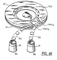
As coins are discharged from the six exit channels 40-45, the coins are guided
down toward six corresponding bag stations BS by six arcuate guide channels 50, as
shown in FIGS. 17 and 18. Only two of the six bag stations BS are illustrated in
FIG. 17, and one of the stations is illustrated in FIG. 18.
As the coins leave the lower ends of the guide channels 50, they enter
corresponding cylindrical guide tubes 51 which are part of the bag stations BS. The
lower ends of these tubes 51 flare outwardly to accommodate conventional clamping-ring
arrangements for mounting coin bags B directly beneath the tubes 51 to receive
coins therefrom.
As can be seen in FIG. 18, each clamping-ring arrangement includes a support
bracket 71 below which the corresponding coin guide tube 51 is supported in such a
way that the inlet to the guide tube is aligned with the outlet of the corresponding
guide channel. A clamping ring 72 having a diameter which is slightly larger than
the diameter of the upper portions of the guide tubes 51 is slidably disposed on each
guide tube. This permits a coin bag B to be releasably fastened to the guide tube 51
by positioning the mouth of the bag over the flared end of the tube and then sliding
the clamping ring down until it fits tightly around the bag on the flared portion of the
tube, as illustrated in FIG. 18. Releasing the coin bag merely requires the clamping
ring to be pushed upwardly onto the cylindrical section of the guide tube. The
clamping ring is preferably made of steel, and a plurality of magnets 73 are disposed
on the underside of the support bracket 71 to hold the ring 72 in its released position
while a full coin bag is being replaced with an empty bag.
Each clamping-ring arrangement is also provided with a bag interlock switch
for indicating the presence or absence of a coin bag at each bag station. In the
illustrative embodiment, a magnetic reed switch 74 of the "normally-closed" type is
disposed beneath the bracket 71 of each clamping-ring arrangement. The switch 74
is adapted to be activated when the corresponding clamping ring 72 contacts the
magnets 73 and thereby conducts the magnetic field generated by the magnets 73 into
the vicinity of the switch 74. This normally occurs when a previously clamped fill
coin bag is released and has not yet been replaced with an empty coin bag. A similar
mechanism is provided for each of the other bag stations BS.
As described above, two different exit channels are provided for each coin
denomination. Consequently, each coin denomination can be discharged at either of
two different locations around the periphery of the guide plate 12, i.e., at the outer
ends of the channels 40 and 41 for the dimes, at the outer ends of the channels 43
and 44 for the nickels, and at the outer ends of the channels 45 and 46 for the
quarters. In order to select one of the two exit channels available for each
denomination, a controllably actuatable shunting device is associated with the first of
each of the three pairs of similar exit channels 40-41, 42-43 and 44-45. When one of
these shunting devices is actuated, it shunts coins of the corresponding denomination
from the first to the second of the two exit channels provided for that particular
denomination.
Turning first to the pair of exit channels 40 and 41 provided for the dimes, a
vertically movable bridge 80 is positioned adjacent the inner edge of the first channel
40, at the entry end of that channel. This bridge 80 is normally held in its raised,
retracted position by means of a spring 81 (FIG. 14), as will be described in more
detail below. When the bridge 80 is in this raised position, the bottom of the bridge
is flush with the top wall of the channel 40, as shown in FIG. 14, so that dimes D
enter the channel 40 and are discharged through that channel in the normal manner.
When it is desired to shunt dimes past the first exit channel 40 to the second
exit channel 41, a solenoid SD (FIGS. 14, 15 and 19) is energized to overcome the
force of the spring 81 and lower the bridge 80 to its advanced position. In this
lowered position, shown in FIG. 15, the bottom of the bridge 80 is flush with the
lowermost surface 22b of the guide plate 12, which has the effect of preventing dimes
D from entering the exit channel 40. Consequently, the quarters are rotated past the
exit channel 40 by the rotating disc, sliding across the bridge 80, and enter the
second exit channel 41.
To ensure that precisely the desired number of dimes are discharged through
the exit channel 40, the bridge 80 must be interposed between the last dime for any
prescribed batch and the next successive dime (which is normally the first dime for
the next batch). To facilitate such interposition of the bridge 80 between two
successive dimes, the dimension of the bridge 80 in the direction of coin movement is
relatively short, and the bridge is located along the edges of the coins, where the
space between successive coins is at a maximum. The fact that the exit channel 40 is
narrower than the coins also helps ensure that the outer edge of a coin will not enter
the exit channel while the bridge is being moved from its retracted position to its
advanced position. In fact, with the illustrative design, the bridge 80 can be
advanced after a dime has already partially entered the exit channel 40, overlapping
all or part of the bridge, and the bridge will still shunt that dime to the next exit
channel 41.
Vertically movable bridges 90 and 100 (FIG. 2) located in the first exit
channels 42 and 44 for the nickels and quarters, respectively, operate in the same
manner as the bridge 80. Thus, the nickel bridge 90 is located along the inner edge
of the first nickel exit channel 42, at the entry end of that exit channel. The bridge
90 is normally held in its raised, retracted position by mans of a spring. In this
raised position the bottom of the bridge 90 is flush with the top wail of the exit
channel 42, so that nickels enter the channel 42 and are discharged through that
channel. When it is desired to divert nickels to the second exit channel 43, a
solenoid SN (FIG. 19) is energized to overcome the force of the spring and lower the
bridge 90 to its advanced position, where the bottom of the bridge 60 is flush with
the lowermost surface 22b of the guide plate 12. When the bridge 90 is in this
advanced position, the bridge prevents any coins from entering the first exit channel
42. Consequently, the nickels slide across the bridge 90, continue on to the second
exit channel 43 and are discharged therethrough. The quarter bridge 100 (FIG. 2)
and its solenoid SQ (FIG. 19) operate in exactly the same manner. The edges of all
the bridges 80, 90 and 100 are preferably chamfered to prevent coins from catching
on these edges.
The details of the actuating mechanism for the bridge 80 are illustrated in
FIGS. 14 and 15. The bridges 90 and 100 have similar actuating mechanisms, and
thus only the mechanism for the bridge 80 will be described. The bridge 80 is
mounted on the lower end of a plunger 110 which slides vertically through a guide
bushing 111 threaded into a hole bored into the guide plate 12. The bushing 111 is
held in place by a locking nut 112. A smaller hole 113 is formed in the lower
portion of the plate 12 adjacent the lower end of the bushing 111, to provide access
for the bridge 80 into the exit channel 40. The bridge 80 is normally held in its
retracted position by the coil spring 81 compressed between the locking nut 112 and a
head 114 on the upper end of the plunger 110. The upward force of the spring 81
holds the bridge 80 against the lower end of the bushing 111.
To advance the plunger 110 to its lowered position within the exit channel 40
(FIG. 15), the solenoid coil is energized to push the plunger 110 downwardly with a
force sufficient to overcome the upward force of the spring 81. The plunger is held
in this advanced position as long as the solenoid coil remains energized, and is
returned to its normally raised position by the spring 81 as soon as the solenoid is deenergized.
Solenoids SN and SQ control the bridges 90 and 100 in the same manner
described above in connection with the bridge 80 and the solenoid SD.
As the coins move along the wall 31 of the referencing recess 30, the outer
edges of all coin denominations are at the same radial position at any given angular
location along the edge. Consequently, the inner edges of coins of different
denominations are offset from each other at any given angular location, due to the
different diameters of the coins (see FIG. 2). These offset inner edges of the coins
are used to separately count each coin before it leaves the referencing recess 30.
As can be seen in FIGS. 2 and 10-12, three coin sensors S1, S2 and S3 in the
form of insulated electrical contact pins are mounted in the upper surface of the
recess 30. The outermost sensor S1 is positioned so that it is contacted by all three
coin denominations, the middle sensor S2 is positioned so that it is contacted only by
the nickels and quarters, and the innermost sensor S3 is positioned so that it is
contacted only by the quarters. An electrical voltage is applied to each sensor so
that when a coin contacts the pin and bridges across its insulation, the voltage source
is connected to ground via the coin and the metal head surrounding the insulated
sensor. The grounding of the sensor during the time interval when it is contacted by
the coin generates an electrical pulse which is detected by a counting system
connected to the sensor. The pulses produced by coins contacting the three sensors
S1, S2 and S3 will be referred to herein as pulses P1, P2 and P3, respectively, and
the accumulated counts of those pulses in the counting system will be referred to as
counts C1, C2 and C3, respectively.
As a coin traverses one of the sensors, intermittent contact can occur between
the coin and the sensor because of the contour of the coin surface. Consequently, the
output signal from the sensor can consist of a series of short pulses rather than a
single wide pulse, which is a common problem referred to as "contact bounce." This
problem can be overcome by simply detecting the first pulse and then ignoring
subsequent pusses during the time interval required for one coin to cross the sensor.
Thus, only one pulse is detected for each coin that contacts the sensor.
The outer sensor S1 contacts all three coin denominations, so the actual dime
count CD is determined by subtracting C2 (the combined quarter and nickel count)
from C1 (the combined count of quarters, nickels and dimes). The middle sensor S2,
contacts both the quarters and the nickels, so the actual nickel count CN is
determined by subtracting C3 (the quarter count) from C2 (the combined quarter and
nickel count). Because the innermost sensor S3 contacts only quarters, the count C3
is the actual quarter count CQ.
Another counting technique uses the combination of (1) the presence of a
pulse P1 from the sensor S1 and (2) the absence of a pulse P2 from the sensor S2 to
detect the presence of a dime. A nickel is detected by the combination of (1) the
presence of a pulse P2 from the sensor S2 and (2) the absence of a pulse P3 from
sensor S3, and a quarter is detected by the presence of a pulse P3 from the sensor
S3. The presence or absence of the respective pulses can be detected by a simple
logic routine which can be executed by either hardware or software.
To permit the simultaneous counting of prescribed batches of coins of each
denomination using the first counting technique described above, i.e., the subtraction
algorithm, counts C
2 and C
3 must be simultaneously accumulated over two different
time periods. For example, count C
3 is the actual quarter count C
Q, which normally
has its own operator-selected limit C
QMAX. While the quarter count
CQ (= C3) is
accumulating toward its own limit C
QMAX, however, the nickel count
CN (= C2 -
C3) might reach its limit C
NMAX and be reset to zero to start the counting of
another batch of nickels. For accurate computation of C
N following its reset to zero,
the count C
3 must also be reset at the same time. The count C
3, however, is still
needed for the ongoing count of quarters; thus the pulses P
3 are supplied to a second
counter C
3 which counts the same pulses P
3 that are counted by the first counter C
3
hut is reset each time the counter C
2 is reset. Thus, the two counters C
3 and C
3
count the same pulses P
3, but can be reset to zero at different times.
The same problem addressed above also exists when the count C
1 is reset to
zero, which occurs each time the dime count C
D reaches its limit C
MAX. That is,
the count C
2 is needed to compute both the dime count C
D and the nickel count C
N,
which are usually reset at different times. Thus, the pulses P
2 are supplied to two
different counters C
2 and C
2. The first counter C
2 is reset to zero only when the
nickel count C
N reaches its C
NMAX, and the second counter is reset to zero each
time C
1 is reset to zero when C
D reaches its limit C
DMAX.
Whenever one of the counts CD, CN or CQ reaches its limit, a control signal
is generated to initiate a bag-switching or bag-stop function.
For the bag-switching function, the control signal is used to actuate the
movable shunt within the first of the two exit channels provided for the appropriate
coin denomination. This enables the coin sorter to operate continuously (assuming
that each full coin bag is replaced with an empty bag before the second bag for that
same denomination is filled) because there is no need to stop the sorter either to
remove full bags or to remove excess coins from the bags.
For a bag-stop function, the control signal preferably stops the drive for the
mating disc and at the same time actuates a brake for the disc. The disc drive can
be stopped either by de-energizing the drive motor or by actuating a clutch which decouples
the drive motor from the disc. An alternative bag-stop system uses a
movable diverter within a coin-recycling slot located between the counting sensors
and the exit channels. Such a recycling diverter is described, for example, in U.S.
Patent No. 4,564,036 issued January 14, 1986, for "Coin Sorting System With
Controllable Stop."
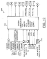
Referring now to FIG. 19, there is shown an upper level block diagram of an
illustrative microprocessor-based control system 200 for controlling the operation of a
coin sorter incorporating the counting and sorting system of this invention. The
control system 200 includes a central processor unit (CPU) 201 for monitoring and
regulating the various parameters involved in the coin sorting/counting and bag-stopping
and switching operations. The CPU 201 accepts signals from (1) the bag-interlock
switches 74 which provide indications of the positions of the bag-clamping
rings 72 which are used to secure coin bags B to the six coin guide tubes 51, to
indicate whether or not a bag is available to receive each coin denomination, (2) the
three coin sensors S1-S3, (3) an encoder sensor E5 and (4) three coin-tracking
counters CTCD, CTCN and CTCQ. The CPU 201 produces output signals to
control the three shunt solenoids SD, SN and SQ, the main drive motor M1, an
auxiliary drive motor M2, a brake B and the three coin-tracking counters.
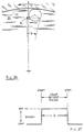
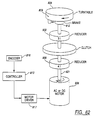
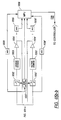
A drive system for the mating disc, for use in conjunction with the control
system of FIG. 19, is illustrated in FIG. 16. The disc is normally driven by a main
a-c. drive motor M1 which is coupled directly to the coin-carrying disc 13 through a
speed reducer 210. To stop the disc 13, a brake B is actuated at the same time the
main motor M1 is de-energized. To permit precise monitoring of the angular
movement of the disc 13, the outer peripheral surface of the disc carries a encoder
in the form of a large number of uniformly spaced indicia 211 (either optical or
magnetic) which can he sensed by an encoder sensor 212. In the particular example
illustrated, the disc has 720 indicia 211 so that the sensor 212 produces an output
pulse for every 0.5° of movement of the disc 13.
The pulses from the encoder sensor 212 are supplied to the three coin-tracking
down counters CTDD, CTCN and CTCQ for separately monitoring the movement of
each of the three coin denominations between fixed points on the sorting head. The
outputs of these three counters CTCD, CTCN and CTCQ can then be used to
separately control the actuation of the bag-switching bridges 80, 90 and 100 and/or
the drive system. For example, when the last dime in a prescribed batch has been
detected by the sensors S1-S3, the dime-tracking counter CTCD is preset to count the
movement of a predetermined number of the indicia 211 on the disc periphery past
the encoder sensor 212. This is a way of measuring the movement of the last dime
through an angular displacement that brings that last dime to a position where the
bag-switching bridge 80 should be actuated to interpose the bridge between the last
dime and the next successive dime.
In the sorting head of FIG. 2, a dime must traverse an angle of 20° to move
from the position where it has just cleared the last counting sensor S1 to the position
where it has just cleared the bag-switching bridge 80. At a disc speed of 250 rpm,
the disc turns -- and the coin moves -- at a rate of 1.5° per millisecond. A typical
response time for the solenoid that moves the bridge 80 is 6 milliseconds (4 degrees
of disc movement), so the control signal to actuate the solenoid should be transmitted
when the last dime is 4 degrees from its bridge-clearing position. In the case where
the encoder has 720 indicia around the circumference of the disc, the encoder sensor
produces a pulse for ever 0.5° of disc movement. Thus the coin-tracking counter
CTCD for the dime is present to 32 when the last dime is sensed, so that the counter
CTCD counts down to zero, and generates the required control signal, when the dime
has advanced 16° beyond the last sensor S1. This ensures that the bridge 80 will be
moved just after it has been cleared by the last dime, so that the bridge 80 will be
interposed between that last dime and the next successive dime.
In order to expand the time interval available for any of the bag-switching
bridges to be interposed between the last coin in a prescribed batch and the next
successive coin of that same denomination, control means may be provided for
reducing the speed of the rotating disc 13 as the last coin in a prescribed batch is
approaching the bridge. Reducing the speed of the rotating disc in this brief time
interval has little effect on the overall throughput of the system, and yet it
significantly increases the time interval available between the instant when the trailing
edge of the last coin clears the bridge and the instant when the leading edge of the
next successive coin reaches the bridge. Consequently, the timing of the interposing
movement of the bridge relative to the coin flow past the bridge becomes less critical
and, therefore, it becomes easier to implement and more reliable in operation.
Reducing the speed of the rotating disc is preferably accomplished by reducing
the speed of the motor which drives the disc. Alternatively, this speed reduction can
be achieved by actuation of a brake for the rotating disc, or by a combination of
brake actuation and speed reduction of the drive motor.
One example of a drive system for controllably reducing the speed of the disc
13 is illustrated in FIG. 16. This system includes an auxiliary d-c. motor M2
connected to the drive shaft of the main drive motor M1 through a timing belt 213
and an overrun clutch 214. The speed of the auxiliary motor M2 is controlled by a
drive control circuit 215 through a current sensor 216 which continuously monitors
the armature current supplied to the auxiliary motor M2. When the main drive motor
M1 is de-energized, the auxiliary d-c. motor M2 can be quickly accelerated to its
normal speed while the main motor M1 is decelerating. The output shaft of the
auxiliary motor turns a gear which is connected to a larger gear through the timing
belt 213, thereby forming a speed reducer for the output of the auxiliary motor M2.
The overrun clutch 214 is engaged only when the auxiliary motor M2 is energized,
and serves to prevent the rotational speed of the disc 13 from decreasing below a
predetermined level while the disc is being driven by the auxiliary motor.
Returning to FIG. 19, when the prescribed number of coins of a prescribed
denomination has been counted for a given coin batch, the controller 201 produces
control signals which energize the brake B and the auxiliary motor M2 and de-energize
the main motor M1. The auxiliary motor M2 rapidly accelerates to its
normal speed, while the main motor M1 decelerates. When the speed of the main
motor is reduced to the speed of the overrun clutch 214 driven by the auxiliary
motor, the brake overrides the output of the auxiliary motor, thereby causing the
armature current of the auxiliary motor to increase rapidly. When this armature
current exceeds a preset level, it initiates de-actuation of the brake, which is then
disengaged after a short time delay. After the brake is disengaged, the armature
current of the auxiliary motor drops rapidly to a normal level needed to sustain the
normal speed of the auxiliary motor. The disc then continues to be driven by the
auxiliary motor alone, at a reduced rotational speed, until the encoder sensor 212
indicates that the last coin in the batch has passed the position where that coin has
cleared the bag-switching bridge in the first exit slot for that particular denomination.
At this point the main drive motor is re-energized, and the auxiliary motor is de-energized.
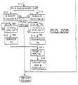
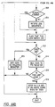
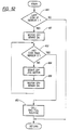
Referring now to FIG. 20, there is shown a flow chart 220 illustrating the
sequence of operations involved in utilizing the bag-switching system of the
illustrative sorter of FIG. 1 in conjunction with the microprocessor-based system
discussed above with respect to FIG. 19.
The subroutine illustrated in FIG. 20 is executed multiple times in every
millisecond. Any given coin moves past the coin sensors at a rate of about 1.5° per
millisecond. Thus, several milliseconds are required for each coin to traverse the
sensors, and so the subroutine of FIG. 20 is executed several times during the sensor-traversing
movement of each coin.
The first six steps 300-305 in the subroutine of FIG. 20 determine whether the
interrupt controller has received any pulses from the three sensors S
1-S
3 If the
answer is affirmative for any of the three sensors, the corresponding count C
1, C
2,
C
2, C
3 and C
3 is incremented by one. Then at
step 306 the actual dime
count C
D is computed by subtracting count C
2 from C
1. The resulting value C
D is
then compared with the current selected limit value C
DMAX at
step 307 to determine
whether the selected number of dimes has passed the sensors. If the answer is
negative, the subroutine advances to step 308 where the actual nickel count C
N is
computed by subtracting count C
3 from C
2. The resulting value C
N is then
compared with the selected nickel limit value C
NMAX at
step 309 to determine
whether the selected number of nickels has passed the sensors. A negative answer at
step 309 advances the program to step 310 where the quarter count
CQ (=C3) is
compared with C
DMAX to determine whether the selected number of quarters has
been counted.
When one of the actual counts CD, CN or CQ reaches the corresponding limit
CDMAX, CNMAX or CQMAC, an affirmative answer is produced at step 311, 312
or 313.
An affirmative answer at step 311 indicates that the selected number of dimes
has been counted, and thus the bridge 80 in the first exit slot 40 for the dime must be
actuated so that it diverts all dimes following the last dime in the completed batch.
To determine when the last dime has reached the predetermined position where it is
desired to transmit the control signal that initiates actuation of the solenoid SD, step
311 presets the coin-tracking counter CTCD to a value PD. The counter CTCD then
counts down from PD in response to successive pulses from the encoder sensor ES as
the last dime is moved from the last sensor S3 toward the bridge 80. To control the
speed of the dime so that it is moving at a known constant speed during the time
interval when the solenoid SD is being actuated, step 314 turns off the main drive
motor M1 and turns on the auxiliary d-c. drive motor M2 and the brake B. This
initiates the sequence of operations described above, in which the brake B is engaged
while the main drive motor M1 is decelerating and then disengaged while the
auxiliary motor M2 drives the disc 13 so that the last dime is moving at a controlled
constant speed as it approaches and passes the bridge 80.
To determine whether the solenoid SD must be energized or de-energized,
step 315 of the subroutine determines whether the solenoid SD is already energized.
An affirmative response at step 315 indicates that it is bag B that contains the preset
number of coins, and thus the system proceeds to step 316 to determine whether bag
A is available. If the answer is negative, indicating that bag B is not available, then
there is no bag available for receiving dimes and the sorter must be stopped.
Accordingly, the system proceeds to step 317 where the auxiliary motor M2 is turned
off and the brake B is turned on to stop the disc 13 after the last dime is discharged
into bag B. The sorter cannot be re-started again until the bag-interlock switches for
the dime bags indicate that the full bag has been removed and replaced with an empty
bag.
An affirmative answer at step 316 indicates that bag A is available, and thus
the system proceeds to step 318 to determine whether the coin-tracking counter
CTCD has reached zero, i.e., whether the OVFLD signal is on. The system
reiterates this query until OVFLD is on, and then advances to step 319 to generate a
control signal to de-energize the solenoid SD so that the bridge 80 is moved to its
retracted (upper) position. This causes all the dimes for the next coin batch to enter
the first exit channel 40 so that they are discharged into bag A.
A negative answer at step 315 indicates the full bag is bag A rather than bag
B, and thus the system proceeds to step 320 to determine whether bag B is available.
If the answer is negative, it means that neither bag A nor bag B is available to
receive the dimes, and thus the sorter is stopped by advancing to step 317. An
affirmative answer at step 320 indicates that bag B is, in fact, available, and thus the
system proceeds to step 321 to determine when the solenoid SD is to be energized, in
the same manner described above for step 318. Energizing the solenoid SD causes
the bridge 80 to be advanced to its lower position so that all the dimes for the next
batch are shunted past the first exit channel 40 to the second exit channel 41. The
control signal for energizing the solenoid is generated at step 321 when step 320
detects that OVFLD is on.
Each time the solenoid S
D is either energized at
step 322 or de-energized at
step 319, the subroutine resell the counters C
1 and C
2 at
step 323, and turns off the
auxiliary motor M2 and the brake B and turns on the main drive motor M1 at
step
324. This initializes the dime-counting portion of the system to begin the counting of
a new batch of dimes.
It can thus be seen that the sorter can continue to operate without interruption,
as long as each full bag of coins is removed and replaced with an empty bag before
the second bag receiving the same denomination of coins has been filled. The
exemplary sorter is intended for handling coin mixtures of only dimes, nickels and
quarters, but it will be recognized that the arrangement described for these three
coins in the illustrative embodiment could be modified for any other desired coin
denominations, depending upon the coin denominations in the particular coin mixtures
to be handled by the sorter.
An alternative coin-sensor arrangement is illustrated in FIGS. 21-23. In this
arrangement that portion of the top surface of the referencing recess 30 that contains
the counting sensors S1-S3 is stepped so that each sensor is offset from the other two
sensors in the axial (vertical) direction as well as the radial (horizontal) direction.
Thus, the steps 300 and 301 form three coin channels 302, 303 and 304 of different
widths and depths. Specifically, the deepest channel 302 is also the narrowest
channel, so that it can receive only dimes; the middle channel 303 is wide enough to
receive nickels but not quarters; and the shallowest channel 304 is wide enough to
receive quarters. The top surfaces of all three channels 302-304 are close enough to
the pad 16 to press all three coin denominations into the pad.
The three counting sensors S1, S2 and S3 are located within the respective
channels 302, 202 and 304 so that each sensor is engaged by only one denomination
of coin. For example, the sensor S1 engages the dimes in the channel 302, but
cannot be reached by nickels or quarters because the channel 302 is too narrow to
receive coins larger than dimes. Similarly, the sensor S2 is spaced radially inwardly
from the inner edges of the dimes so that it engages only nickels in the channel 303.
The sensor S3 engages quarters in the channel 304, but is spaced radially inwardly
from both the nickels and the dimes.
It will be appreciated from the foregoing description of the sensor
arrangement of FIGS. 21-23 that this arrangement permits direct counting of the
various coin denominations, without using the subtraction algorithm or the pulse-processing
logic described above in connection with the embodiment of FIGS. 2-15.
FIGS. 24-28 show another modification of the sorting head of FIGS. 2-15 to
permit the counting and sorting of coins of six different denominations, without
automatic bag switching. This sorting head has six different exit channels 40
-45
,
one for each of six different denominations, rather than a pair of exit channels for
each denomination.
In the counting system of FIGS. 24-28, the six sensors S1-S6 are spaced apart
from each other in the radial direction so that one of the sensors is engaged only by
half dollars, and each of the other sensors is engaged by a different combination of
coin denominations. For example, as illustrated in FIGS. 25 and 26, the sensor S4,
engages not only quarters (FIG. 25) but also all larger coins (FIG. 26), while missing
all coins smaller than the sensor S2 engaging a penny (FIG. 27) but missing a dime
(FIG. 28).
The entire array of sensors produces a unique combination of signals for each
different coin denomination, as illustrated by the following table where a "1"
represents engagement with the sensor and a "0" represents non-engagement with the
sensor:
| | P1 | P2 | P3 | P4 | P5 | P6 |
| 10¢ | 1 | 0 | 0 | 0 | 0 | 0 |
| 1¢ | 1 | 1 | 0 | 0 | 0 | 0 |
| 5¢ | 1 | 1 | 1 | 0 | 0 | 0 |
| 25¢ | 1 | 1 | 1 | 1 | 0 | 0 |
| $1 | 1 | 1 | 1 | 1 | 1 | 0 |
| 50¢ | 1 | 1 | 1 | 1 | 1 | 1 |
by analyzing the combination of signals produced by the six sensors S
1-S
6 in
response to the passage of any coin thereover, the denomination of that coin is
determined immediately, and the actual count for that denomination can be
incremented directly without the use of any subtraction algorithm. Also, this sensor
arrangement minimizes the area of the sector that must be dedicated to the sensors on
the lower surface of the sorting head.
The analysis of the signals produced by the six sensors S1-S6 in response to
any given coin can be simplified by detecting only that portion of each combination
of signals that is unique to one denomination of coin. As can be seen from the above
table, these unique portions are P1=0 and P2=1 for the dime, P2=0 and P3=1 for
the penny, P3=0 and P4=1 for the nickel, P4=0 and P5=1 for the quarter, P5=0
and P6=1 for the dollar, and P6=1 for the half dollar.
As an alterative to the signal-processing system described above, the counts
C
1-C
6 of the pulses P
1-P
6 from the six sensors S
1-S
6 in FIGS. 24-28 may be
processed as follows to yield actual counts C
D, C
P, C
N, C
Q, C
S and C
H of dimes,
pennies, nickels, quarters, dollars and half dollars:
FIGS. 29-31 illustrate a six-denomination sorting head using yet another coin-sensor
arrangement. In this arrangement the sensors S1-S6 are located at the
upstream end of the referencing recess 30, in the outer wall 31 of that recess.
Because the coins leave the outwardly spiraling channel 25 with the inner edges of
all coin denominations at a common radius, the outer edges of the coins are offset
from each other according to the diameters (denominations) of the coins.
Consequently, coins of different denominations engage the inwardly spiralling wall 31
at different circumferential positions, and the six sensors S1-S6 are located at
different circumferential positions so that each sensor is engaged by a different
combination of denominations.
The end result of the sensor arrangement of FIGS. 29-31 is the same as that
of the sensor arrangement of FIGS. 24-28. That is, the sensor S1 is engaged by six
denominations, sensor S2 is engaged by five denominations, sensor S3 is engaged by
four denominations, sensor S4 is engaged by three denominations,s sensor S5 is
engaged by two denominations, and sensor S6 is engaged by only one denomination.
The counts C1-C6 of the pulses P1-P6 from the six sensors S1-S6 may be processed
in the same manner described above for FIGS. 24-28 to yield actual counts CD, CP,
CN, CQ, CS and CH.
As shown in FIG. 31, the sensors used in the embodiment of FIGS. 29-31
may be formed as integral parts of the outer wall 31 of the recess 30. Thus, the
insulated contact pins may be installed in the metal plate used to form the sorting
head before the various contours are formed by machining the surface of the plate.
Then when the recess 30 is formed in the plate, the cutting tool simply cuts through a
portion of each contact pin just as though it were part of the plate.
Still another coin sensor arrangement is shown in FIGS. 32 and 33. In this
arrangement only two sensors are used to detect all denominations. One of the
sensors S1, is located in the wall that guides the coins while they are being sensed,
and the other sensor S2 is spaced radially away from the sensor S1 by a distance that
is less than the diameter of the smallest coin to be sensed by S2. Every coin engages
both sensors S1 and S2, but the time interval between the instant of initial
engagement with S2 and the instant of initial engagement with S1 varies according to
the diameter of the coin. A large-diameter coin engages S2 earlier (relative to the
engagement with S1) than a small-diameter coin. Thus, by measuring the time
interval between the initial contacts with the two sensors S1 and S2 for any given
coin, the diameter of that coin can be determined.
Alternatively, the encoder on the periphery of the disc 13 can be used to
measure the angular displacement a of each coin from the time it initially contacts the
sensor S1 until it initially contacts the sensor S2. This angular displacement a
increases as the diameter of the coin increases; so the diameter of each coin can be
determined from the magnitude of the measured angular displacement. This
denomination-sensing technique is insensitive to variations in the rotational speed of
the disc because it is based on the position of the coin, not its speed.
FIGS. 34 and 35 show a modified form of the two-sensor arrangement of
FIGS. 32 and 33. In this case the sensor S1 engages the flat side of the coin rather
than the edge of the coin. Otherwise the operation is the same.
Another modified counting arrangement is shown in FIG. 36. This
arrangement uses a single sensor S1 which is spaced away from the coin-guiding wall
31 by a distance that is less than the diameter of the smallest coin. Each coin
denomination traverses the sensor S1 over a unique range of angular displacement b,
which can be accurately measured by the encoder on the periphery of the disc 13, as
illustrated by the timing diagram in FIG. 37. The counting of pulses from the
encoder sensor 212 is stated when the leading edge of a coin first contacts the sensor
S1, and the counting is continued until the trailing edge of the coin clears the sensor.
As mentioned previously, the sensor will not usually produce a uniform flat pulse,
but there is normally a detectable rise or fall in the sensor output signal when a coin
first engages the sensor, and again when the coin clears the sensor. Because each
coin denomination requires a unique angular displacement b to traverse the sensor,
the number of encoder pulses generated during the sensor-traversing movement of the
coin provides a direct indication of the size, and therefore the denomination, of the
coin.
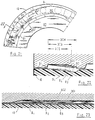
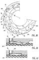
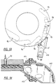
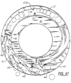
FIGS. 38-43 illustrate a system in which each coin is sensed after it has been
sorted but before it has exited from the rotating disc. One of six proximity sensors
S1-S6 is mounted along the outboard edge of each of the six exit channels 350-355 in
the sorting head. By locating the sensors S1-S6 in the exit channels, each sensor is
dedicated to one particular denomination of coin, and thus it is not necessary to
process the sensor output signals to determine the coin denomination. The effective
fields of the sensors S1-S6 are all located just outboard of the radius Rg at which the
outer edges of all coin denominations are gaged before they reach the exit channels
350-355, so that each sensor detects only the coins which enter its exit channel and
does not detect the coins which bypass that exit channel. Thus, in FIG. 38 the
circumferential path followed by the outer edges of all coins as they traverse the exit
channels is illustrated by the dashed-line arc Rg. Only the largest coin denomination
(e.g., U.S. half dollars) reaches the sixth exit channel 355, and thus the location of
the sensor in this exit channel is not as critical as in the other exit channels 350-354.
It is preferred that each exit channel have the straight side walls shown in
FIG. 38, instead of the curved side walls used in the exit channels of many previous
disc-type coin sorters. The straight side walls facilitate movement of coins through
an exit slot during the jogging mode of operation of the drive motor, after the last
coin has been sensed, which will be described in more detail below.
To ensure reable monitoring of coin movement downstream of the respective
sensors, as well as reliable sensing of each coin, each of the exit channels 350-355 is
dimensioned to press the coins therein down into the resilient top surface of the
rotating disc. This pressing action is a action of not only the depth of the exit
channel, but also the clearance between the lowermost surface of the sorting head and
the uppermost surface of the disc.
To ensure that the coins are pressed into the resilient surface of the rotating
disc, the depth of each of the exit channels 350-355 must be substantially smaller
than the thickness of the coin exited through that channel. In the case of the dime
channel 350, the top surface 356 of the channel is inclined, as illustrated in FIGS. 42
and 43, to tilt the coins passing through that channel and thereby ensure that worn
dimes are retained within the exit channel. As can be seen in FIG. 42, the sensor S1
is also inclined so that the face of the sensor is parallel to the coins passing
thereover.
Because the inclined top surface 356 of the dime channel 350 virtually
eliminates any outer wall in that region of the channel 350, the dime channel is
extended into the gaging recess 357. In the region where the outer edge of the
channel 350 is within the radius Rg, the top surface of the dime channel is flat, so as
to form an outer wall 358. This outer wall 358 prevents coins from moving
outwardly beyond the gaging radius Rg before they have entered one of the exit
channels. As will be described in more detail below, the disc which carries the coins
can recoil slightly under certain stopping conditions, and without the outer wall 358
certain coins could be moved outwardly beyond the radius Rg by small recoiling
movements of the disc. The wall 358 retains the coins within the radius Rg, thereby
preventing the missorting that can occur if a coin moves outside the radius Rg before
that coin reaches its exit channel. The inner wall of the channel 350 in the region
bounded by the wall 358 is preferably tapered at a angle of about 45° to urge coins
engaging that edge toward the outer wall 358.
The inclined surface 356 is terminated inboard of the exit edge 350 of the exit
channel to form a flat surface 360 and a outer wall 361. This wall 361 serves a
purpose similar to that of the wall 358 described above, i.e., it prevents coins from
moving away from the inner wall of the exit channel 350 in the event of recoiling
movement of the disc after a braked stop.
As shown in FIGS. 38, 41 ad 43, the exit end of each exit channel is
terminated along an edge that is approximately perpendicular to the side walls of the
channel. For example, in the case of the dime exit channel 350 shown in FIGS. 41-43,
the exit channel terminates at the edge 350a. Although the upper portion of the
sorting head extends outwardly beyond the edge 350a, that portion of the head is
spaced so far above the disc and the coins (see FIG. 43) that it has no functional
significance.
Having the exit edge of an exit channel perpendicular to the side walls of the
channel is advantageous when the last coin to be discharged from the channel is
followed closely by another coin. That is, a leading coin can be completely released
from the channel while the following coin is still completely contained within the
channel. For example, when the last coin in a desired batch of n coins is closely
followed by coin n+1 which is the first coin for the next batch, the disc must be
stopped after the discharge of coin n but before the discharge of coin n+1. This can
be more readily accomplished with exit channels having exit edges perpendicular to
the side walls.
As soon as any one of the sensors S1-S6 detects the last coin in a prescribed
count, the disc 359 is stopped by de-energizing or disengaging the drive motor and
energizing a brake. In a preferred mode of operation, the disc is initially stopped as
soon as the trailing edge of the "last" or nth coin clears the sensor, so that the nth
coin is still well within the exit channel when the disc comes to rest. The nth coin is
then discharged by jogging the drive motor with one or more electrical pulses until
the trailing edge of the nth coin clears the exit edge of its exit channel. The exact
disc movement required to move the trailing-edge of a coin from its sensor to the exit
edge of its exit channel, can be empirically determined for each coin denomination
and then stored in the memory of the control system. The encoder pulses are then
used to measure the actual disc movement following the sensing of the nth coin, so
that the disc 359 can be stopped at the precise position where the nth coin clears the
exit edge of its exit channel, thereby ensuring that no coins following the nth coin are
discharged.
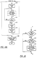
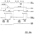
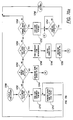
The flow chart of a software routine for controlling the motor and brake
following the sensing of the nth coin of any denomination is illustrated in FIGS. 44-46,
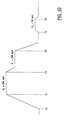
and corresponding timing diagrams are shown in FIGS. 47 and 48. This
software routine operates in conjunction with a microprocessor receiving input signals
from the six proximity sensors S1-S6 and the encoder 212, as well as manually set
limits for the different coin denominations. Output signals from the microprocessor
are used to control the drive motor ad bee for the disc 359. One of the
advantages of this program is that it permits the use of a simple a-c. induction motor
as the only drive motor, and a simple electromagnetic brake. The routine charted in
FIGS. 44a and 44b is entered each time the output signal from any of the sensors S1-S6
changes, regardless of whether the change is due to a coin entering or leaving the
field of the sensor. The microprocessor can proess changes in the output signals
from all six sensors in less time than is required for the smallest coin to traverse its
sensor.
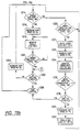
The first step of the routine in FIG. 44a is step 500 which determines whether
the sensor signal represents a leading edge of the coin, i.e., that the change in the
sensor output was caused by metal entering the field of the sensor. The change in
the sensor output is different when metal leaves the field of the sensor. If the answer
at step 500 is affirmative, the routine advances to step 501 to determine whether the
previous coin edge detected by the same sensor was a trailing edge of a coin. A
negative answer indicates that the sensor output signal which caused the system to
enter this routine was erroneous, and thus the system immediately exits from the
routine. An affirmative answer at step 501 confirms that the sensor has detected the
leading edge of a new coin in the exit slot, and this fact is saved at step 502. Step
503 resets a coin-width counter which then counts encoder pulses until a trailing edge
is detected. Following step 503 the system exits from this routine.
A negative response at step 500 indicates that the sensor output just detected
does not represent a leading edge of a coin, which means that it could be a trailing
edge. This negative response advances the routine to step 504 to determine whether
the previous coin edge detected by the same sensor was a leading edge. If the
answer is affirmative, the system has confirmed the detection of a trailing coin edge
following the previous detection of a leading coin edge. This affirmative response at
step 504 advances the routine to step 505 where the fact that a trailing edge was just
detected is saved, and then step 506 determines whether the proper number of
encoder pulses has been counted by the encoder pulses in the interval between the
leading-edge detection and the trailing-edge detection. A negative answer at either
step 504 or step 506 causes the system to conclude that the sensor output signal
which caused the system to enter this routine was erroneous, and thus the routine is
exited.
An affirmative answer at step 506 confirms the legitimate sensing of both the
leading and trailing edges of a new coin moving in the proper direction through the
exit channel, and thus the routine advances to step 507 to determine whether the
sensed coin is an n+1 coin for that particular denomination. If the answer is
affirmative, the routine starts tracking the movement of this coin by counting the
output pulses from the encoder.
At step 509, the routine determines whether the drive motor is already in a
jogging mode. If the answer is affirmative, the routine advances to step 511 to set a
flag indicating that this particular coin denomination requires jogging of the motor.
A negative response at step 509 initiates the jogging mode (to be described below) at
step 510 before setting the flag at step 511.
At step 512, the routine of FIG. 44b determines whether the most recently
sensed coin is over the limit of n set for that particular coin denomination. If the
answer is affirmative, the count for that particular coin is added to a holding register
at step 513, for use in the next com count. A negative response at step 512 advances
the routine to step 514 where the count for this particular coin is added to the current
count register, and then step 515 determines whether the current count in the register
has reached the limit of n for that particular coin denomination. If the answer is
negative, the routine is exited. If the answer is affirmative, a timer is stared at step
516 to stop the disc at the end of a preselected time period, such as 0.15 second, if
no further coins of this particular denomination are sensed by the end of that time
period. The purpose of this final step 516 is to stop the disc when the nth coin has
been discharged, and the time period is selected to be long enough to ensure that the
nth coin is discharged from its exit channel after being detected by the sensor in that
channel. If a further coin of the same denomination is sensed before this time period
has expired, then the disc may be stopped prior to the expiration of the preselected
time period in order to prevent the further coin from being discharged, as wall be
described in more detail below in connection with the jogging sequence routine.
Whenever step 510 is reached in the routine of FIG. 44b, the jog sequence
routine of FIGS. 45a and 45b is entered. The first two steps of this routine are steps
600 and 601 which turn off the drive motor and turn on the brake. This is time t 1 in
the timing diagrams of FIGS. 47 and 48, and a timer is also started at time t 1 to
measure a preselected time interval between t 1 and t 2; this time interval is selected to
be long enough to ensure that, the disc has been brought to a complete stop, as can be
seen from the speed and position curves in FIGS. 47 and 48. Step 602 of the routine
of FIG. 45a determines when the timer t 2 has been reached, and then the brake is
turned off at step 603.
It will be appreciated that the n+1 coin may be reached for more than one
coin denomination at the same time, or at least very close to the same time. Thus,
step 604 of the routine of FIG. 45a determines which of multiple sensed n+1 coins is
closest to its final position. Of course, if an n+1 coin has been sensed for only one
denomination, then that is the coin denomination that is selected at step 604. Step
605 then determines whether the n+1 coin of the selected denomination is in its final
position. This final position is the point at which the n+1 coin has been advanced
far enough to ensure that the nth coin has been fully discharged from the exit
channel, but not far enough to jeopardize the retention of the n+1 coin in the exit
channel. Ideally, the final position of the n+1 coin is the position at which the
leading edge of the n+1 coin is aligned with the exit edge 350a of its exit channel.
When the n+1 coin has reached its final position, step 605 yields an
affirmative response and the routine advances to step 606 where a message is
displayed, to indicate that the nth coin has been discharged. The routine is then
exited. If the response at step 605 is negative, the drive motor is turned on at step
607 and the brake is turned on at step 608. This is time t 3 in the timing diagrams of
FIGS. 47 and 48. After a predetermined delay interval, which is measured at step
609, the brake is turned off at time t 4 (step 610). Up until the time t 4 when the
brake is turned off, the brake overrides the drive motor so that the disc remains
stationary even though the drive motor has been turned on. When the brake is turned
off at time t 4, however, the drive motor begins to turn the disc and thereby advance
both the n+1 coin and the nth coin along the exit channel.
Step 611 determines when the n+1 coin has been advanced through a
preselected number of encoder pulses. When step 611 produces an affirmative
response, the brake is turned on again at step 612 and the motor is turned off at step
613. This is time t 5 in the timing diagrams. The routine then returns to step 602 to
repeat the jogging sequence. This jogging sequence is repeated as many times as
necessary until step 605 indicates that the n+1 coin has reached the desired final
position. As explained above, the final position is the position at which the n+1 coin
is a position which ensures that the nth coin has been discharged from the exit
channel and also ensures that the n+1 coin has not been discharged from the exit
channel. The routine is then exited after displaying the limit message at step 606.
Instead of releasing the brake abruptly at time t 4, as indicated in the timing
diagram of FIG. 47, the brake may be turned only partially off at step 610 and then
released gradually, according to the subroutine of FIG. 46 and the timing diagram of
FIG. 48. In this "soft" brake release mode, step 614 measures small time increments
following time t 4, and at the end of each of these time increments step 615
determines whether the brake is fully on or fully off. If the answer is affirmative,
the subroutine exits to step 611. If the answer is negative, the brake power is
decreased slightly at step 616. This subroutine is repeated each time the jogging
sequence is repeated, until step 615 yields an affirmative response. The resulting
"soft" release of the brake is illustrated by the steps in the brake curve following time
t 4 in FIG. 48.
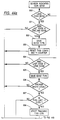
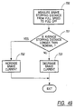
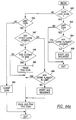
An additional subroutine, illustrated in FIG. 49, automatically adjusts the
energizing current supplied to the brake in order to compensate for variations in the
line voltage, temperature and other variables that can affect the stopping distance
after the brake has been energized. Step 700 of this subroutine measures the stopping
distance each time the brake is turned off. Step 701 then determines whether that
measured stopping distance is longer than a preselected nominal stopping distance. If
the answer is affirmative, the brake current is increased at step 702, and is the
answer is negative, the brake current is decreased at step 703. The subroutine is then
exited.
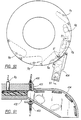
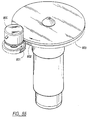
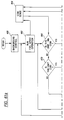
In the modified embodiment of FIGS. 50 and 51, a second sensor S
is
provided outboard of the disc at the end of each exit channel to confirm that the
nth
coin has, in fact, been discharged from the disc. With this arrangement, no encoder
is required and the software routine of FIG. 52 can be utilized. As can
be seen in FIG. 51, the second sensor S
is formed by a
light source 400 mounted in
an extension of the had 401 beyond the
disc 402, and a
photodetector 403 mounted
in the bottom wall on
exit chute 404.
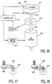
The routine of FIG. 52 begins at
step 650, which determines whether the coin
sensed at the first sensor is the
nth coin in the preselected number of coins of that
denomination. If the answer is negative, the routine is exited. If the answer is
affirmative, the subroutine stops the disc at
step 651 by de-energizing the motor and
energizing the brake. Step 652 then determines whether the
nth coin has been
detected by the second sensor S
.
As long as
step 652 produces a negative answer, indicating that the
nth coin
has not been detected by the second sensor S
the routine advances to step 654 which
turns off the brake and jogs the motor by momentarily energizing the motor with a
controlled pulse. The motor is then immediately turned off again, and the brake is
turned on, at
step 655. The routine then returns to step 652.
When step 652 produces an affirmative answer, indicating that the nth coin
has been detected by the second sensor, a "bag full" routine is entered at step 653.
The "bag full" routine ensures that the disc remains stationary until the full bag is
removed and replaced with an empty bag.
In FIGS. 53 and 54, there is shown another modified embodiment which the
second sensor S
is located entirely in the
exit chute 410. Here again, the second
sensor S
is formed by a
light source 411 and a
photodetector 412, but in this case
both elements are mounted in the
exit chute 410. Also, both the
source 411 and the
detector 412 are spaced away from the outer edge of the disc by a distance which is
approximately the same as the diameter of the particular coin denomination being
discharged at this location. Consequently, whenever the sensor S
detects a new
coin, that coin has already been released from the disc and the sorting head.
FIG. 55 illustrates a preferred encoder 800 to be used in place of the encoder
212 shown in FIG. 16. The encoder 800 has a gear wheel 801 meshing with gear
teeth 802 on the periphery of the metal disc 803. The meshing gear teeth ensure that
the encoder 800 positively tracks the rotational movement of the disc 803.
Referring now to FIG. 56, there is shown another coin handling system, in
accordance with the present invention, which provides coin-discharge control for
coins on a rotating coin disc 808 using a microprocessor-based controller 810. The
controller 810 controls a brake 812 and an AC motor 814, via a motor driver 817, in
response to a coin sensor 809 embedded in the stationary head 811 and an encoder
816. The coin sensor 809 is used to count the number of coins of each denomination
passing the sensor, and the encoder 816 is used to monitor the angular displacement
of a speed reducer 819. The coin sensor 809 may be implemented in a number of
ways, such as those described in connection with FIGS. 17, 24, 29 and 38.
As shown in FIGS. 57 and 58, the speed reducer 819 can be implemented
using a ridged belt 820 to couple the motor drive shaft 821 with a gear 822, or using
a gear train 824, or a combination of both types of speed reducers. Speed reducers
of this type, such as shown in U.S. Patent Nos. 5,021,026 and 5,055,086, are
conventional.
By configuring the encoder 816 such that it monitors the motor-axle side of
the speed reducer 819, each turn of the motor axle 821 is translated to only a fraction
of the angular movement of the coin disc 808, thereby permitting precise monitoring
of the coin disc position. For example, using a speed reducer 819 which has a 5:1
gear ratio, a 100 degree rotation of the motor axle 821 translates to only a 20 degree
rotation of the coin disc 808. The controller 810 uses this translatory arrangement to
determine exactly how far a coin has progressed once it is detected by the coin sensor
on the stationary sorting head.
FIG. 59a illustrates the timing for an exemplary operation of the system
shown in FIG. 56. The first line of the timing diagram of FIG. 59a, depicted by I,
represents the signal output from the coin sensor 809, using the one-hundredth coin
of a particular coin denomination as the limit coin. The second and third lines II and
III of the timing diagram represent, respectively, the spend of the motor 814 and the
power control signal (ON or OFF) to the motor 814. The controller 810 controls the
speed of the motor by using the power control signal (line III) to turn the power to
the motor on and off and to selectively actuate the brake 812. The timing and
magnitude of the brake current is shown on line IV. Line V represents an internal
timing signal used by the controller 810 to determine if too much time has passed
before sensing the limit coin.
Assuming that the controller has been programmed with the one-hundredth
coin of a particular denomination as the limit coin and the ninety-fifth coin of that
denomination as the prelimit coin, the controller runs the motor at full speed until the
prelimit coin is sensed by the coin sensor. When the prelimit coin has been sensed,
the controller initiates immediate deceleration of the rotating disc, and then slowly
advances the disc until the limit coin is sensed, sorted and discharged. This ensures
that the higher speed at which the disc sorts coins does not discharge any coins
beyond the preselected coin limit.
To achieve this goal, in response to sensing the prelimit coin, the controller
sends a signal to a relay or solenoid or other device (not shown in the figures) to shut
down power to the motor. The timing for this shut-down signal is shown on line III
of FIG. 59a in the first falling edge of the motor power control signal. At essentially
the same time the power to the motor is interrupted, the controller sends a signal to
the brake so as to apply maximum braking force against the rotating disc. The
timing for this signal is shown on line IV as the first rising edge of the brake current
signal. A short time later and within about fifty degrees of disc rotation, the rotating
disc is brought from full speed (e.g., 360 RPM) to a static position, as indicated by
the second horizontal line on the speed plot of line II. In the meantime and during
this fifty degree of disc-rotation, the coin sensor has sensed the ninety-sixth and
ninety-seventh coins, depicted on line I.
A short time after the disc is halted, the controller sends a signal to the brake
to apply a reduced braking force against the rotating disc. The timing for this signal
is shown on the IV as the first falling edge of the brake current signal. As depicted
after this first falling edge, this reduced braking force corresponds to a current level
of 0.5 amperes, or about ten percent of the maximum braking force. With the
braking force at this reduced level, the controller next turns the motor on again and
simultaneously activates a two-minute internal timer. The disc begins rotating again
but at a much slower speed, e.g., 120 RPM.
This slower rotation of the disc continues until the earlier of three events
occurs.
The first event is the controller receiving an indication that the first coin
beyond the limit coin (limit + 1) has been sensed. If this condition occurs, the
controller engages the brake and removes power to the motor simultaneously. By the
time the rotation of the disc is stopped, the limit coin will have been rotated out of
the appropriate coin exit path.
The second event is based on a timing signal, preferably internal to the
controller, indicating that 100 milliseconds has lapsed since the limit coin was sensed.
Once the disc has rotated for 100 milliseconds after the limit coin has been sensed at
the reduced speed, the controller can assume that the limit coin has been discharged.
The 100-millisecond period is selected based on the reduced speed of the disc, the
size of the disc and the position of the sensor with respect to the coin-exit channel.
The third event is based on the two-second timing signal shown on line V of
FIG. 59b. The controller begins the timing signal, using an internal counter, once
power has been provided to the motor to initiate the reduced speed (120 RPM) mode.
After the two-second period has lapsed, the controller operates under the assumption
that neither of the first two conditions has occurred or is imminent. In anticipation
that additional full-speed sorting will produce the limit coin, the controller removes
the braking force on the disc completely until the limit coin is sensed and counted. If
there are coins after the limit coin, this resumption to full-speed rotation will
typically cause a coin-discharge overage, the amount of which is dependent on the
number of coins counted in the low speed phase (e.g., 120 RPM). The worst case
overage will be equal to one less than the sorter inherent overage (SIO). The SIO is
the worst coin overage for a specific coin denomination when the disk is stopped
from the full speed.
The probability of not achieving the exact stop is very low and depends on the
coin distribution immediately before the limit is reached. This probability is
described mathematically as follows: if the last N coins are found within R
revolutions for the disc then the overage is zero, where N is the SIO and R is the
number of disc revolutions allowed in the reduced speed mode. Exemplary values
for N and R are 5 and 4, respectively. The actual overages will always be lower
than the SIO number. The value of R is somewhat arbitrary and, if desired, can be
changed to meet the specific coin-sorting application.
The likelihood that 5 coins of a selected denomination will not be found
within 4 disc revolutions is relatively low.
In response to the occurrence of either the first or second event or to sensing
of the limit coin in the third event, the controller sends the appropriate signals to
bring the disc to an immediate halt. Thus, power to the motor is removed and the
controller commands the brake to apply maximum braking force against the rotating
disc. During this phase, the disc is stopped after about seven degrees of disc
rotation. Halting the disc in response to the first event is illustrated in FIG. 59a.
For example, in response to the controller receiving the trailing edge (line I) of the
signal corresponding to sensing the coin after the limit coin, the power to the motor
is shown being removed on the second trailing edge of line III.
As an alternative to the controller being programmed to determine the
occurrence of the first and second of the above three events, a second sensor located
outboard of the rotating disc may be used in combination with the encoder to indicate
to the controller when the limit coin has been discharged from the disc. Because the
outboard sensor cannot alleviate the problem when the limit coin 4X is not sensed after
an extended period of time, in this embodiment the controller is programmed to
determine and react to the occurrence of the third event described above. The disc
arrangement of any of the previously-described implementations may be used, in
combination with an outboard sensor to accomplish this approach. The outboard coin
sensor referred to above is shown for one of the coin-discharge exit paths in FIG. 29,
depicted in dotted lines as S7.
FIG. 59b is another timing diagram showing the operation of the system of
FIG. 56 in response to the above-described third event. By comparing the signals of
the timing diagrams of FIGS. 59a and 59b, it can be seen that operation of the
system is identical through the sensing of the ninety-ninth coin. After sensing this
coin, however, the limit coin is not sensed within the two-second period of the timing
signal represented by line V of FIG. 59b. At the end of this two-second period, the
controller completely removes the braking force on the disc, so that the rotation of
the disc ramps up to maximum speed until the limit coin is sensed. Where this two-second
period ends (trailing edge of the signal depicted by line V of FIG. 59b), the
speed of the motor is shown ramping up to full speed at 360 RPM on line II of FIG.
59b.
Alternatively, the controller is programmed to ramp up the disc rotation speed
only for a predetermined period of time, after which the controller displays a signal
to the system user indicating whether or not the limit coin was reached and, if not,
the amount of the shortage.
An acceptable coin sorting system, according to the configuration of the
system of FIG. 56, includes the exact bag stop 13-inch diameter sorting head used on
Cummins Model 3400, modified as illustrated in FIG. 56 to include the in-head
sensors.
FIG. 60 illustrates a system for controlling the AC motor shown in FIG. 56 to
obtain the low-speed (120 RPM) mode. The block diagram of FIG. 60 includes a
tachometer 840 proriding a signal representative of the speed of the AC motor, and
two comparators 842 and 844. The comparators 842 and 844 compare the speed of
the motor, using the signal provided by the tachometer 840, with respective high and
low speed thresholds, VH and VL, to determine when the motor is rotating too fast
and too slow. By setting the high and low speed thresholds, VH and VL, so that
their average corresponds to the low speed disc rotation, the power to the motor is
controlled to maintain an average speed corresponding to the low speed disc rotation.
For example, for a desired average speed of 120 RPM, the respective high and low
speed thresholds, VH and VL, can be set at levels corresponding to disc speeds of
125 RPM and 115 RPM. When the spend of the disc exceeds the 125 RPM limit,
the output of the comparator 842 provides a high-level output signal to indicate that
the power to the motor should be shut off. When the spend of the disc falls below
the 115 RPM limit, the output of the comparator 844 provides a low-level output
signal to indicate that the power to the motor should be turned back on. In this way,
the power to the motor is pulsed on and off to effect a much more controlled disc
speed.
The output signals from the comparators 842 and 844 are coupled to the
respective S-R inputs of an S-R flip-flop 846, which provides an output signal Q
based on the signals at the S-R inputs. The output signal Q is coupled to a switch
848, via an AND gate 850 and an OR gate 851, to control power to the AC motor.
When the output of the comparator 844 is high, the S-R flip-flop 846 produces a
high-level output signal, providing power to the motor to speed up the motor. When
the output of the comparator 842 is high, the S-R flip-flop 846 produces a low-level
output signal, causing the switch 848 to disconnect power to the motor to slow down
the motor. When the signal provided by the tachometer 840 indicates that the motor
speed corresponds to a speed which is between the high and low threshold levels, VH
and VL, the outputs of the comparators 842 and 844 are low and the S-R flip-flop
does not change state.
The output of the comparator 844 should not be high when the output of the
comparator 842 is high, because the outputs of the comparators 842 and 844 provide
mutually exclusive signals. Either the motor is too fast or it is too slow; it cannot be
too fast and too slow. To ensure that this logical boundary is not violated upon
powering-up the comparators 842 and 844 and the flip-flop 846, an R-C circuit 852 is
used in combination with an AND gate at the S input to the S-R flip-flop 846. The
RC time constant for the R-C circuit 852 is therefore selected so that the S input to
the S-R flip-flop 846 remains low, via the AND gate 854, until the comparators 842
and 844 and the flip-flop 846 are fully powered.
The AND gate 850 receives the Q output from the S-R flip-flop 846 and a
low-speed enable signal from the controller, so that the low-speed mode is operative
only when the controller provides the low-speed enable signal (high). When the
controller does not provide the low-spend enable signal, the output of the AND gate
850 is low and the flip-flop 846 is disabled.
The OR gate 851 receives the output from the AND gate 850 and a full-spend
enable signal from the controller, so that the motor operates at full speed whenever
the controller provides the full-speed enable signal (high). When the controller does
not provide the full-speed enable signal, the output of the OR gate 851 is controlled
by the Q output from the S-R flip-flop 846 and the low-spend enable signal. To shut
down power to the motor, the controller sends both the low-spend enable signal and
the full-speed enable signal low.
Turning now to FIG. 61, a flow chart shows how the controller (implemented,
for example, using a microcomputer) of FIG. 56 may be programmed in accordance
with the discussion of FIGS. 56-60 for sorting and counting coins of a particular coin
denomination from coins of multiple denominations. Substantive execution begins at
block 860 where the controller performs background control functions, such as
register and display initialization and timer updates. At block 862, the controller
initiates full-speed sorting by turning on the motor and removing the braking force, if
any, from the disc.
From block 862, flow proceeds to either block 864 or 866. Block 864 depicts
an interrupt routine which is executed in response to the coin sensor (for the
particular coin denomination) reporting to the controller that a coin has been sensed,
and the interrupt routine may be entered from any of blocks 862-882. The interrupt
routine is used to increment the coin count for the particular denomination. Once the
interrupt routine has been completed or if no coin is sensed, flow proceeds to block
866, where the controller determines if the coin count has reached the prelimit count,
N-1. If the coin count has reached the prelimit count, flow proceeds to block 868
where the controller runs the prelimit speed and begins counting down for the two-second
timeout. If the coin count has not reached the prelimit count, flow proceeds
to block 870 where the controller determines if this most-recently sensed coin is the
limit coin.
At block 870, if this most-recently sensed coin is not the limit coin flow
proceeds to block 872 where the controller determines if this coin is the first coin
after the limit coin. If the coin is the first coin after the limit coin, flow proceeds to
block 874 where the controller disconnects power from the motor and applies full
braking force to the disc. If the coin is not the first coin after the limit coin, the
controller concludes that the prelimit count has not been reached and flow returns to
block 866 where the controller continues execution with the disc sorting at full-speed.
Referring back to blocks 866 and 868, once the controller begins executing
the pre-limit speed for the disc, the controller checks its internal timer to determine if
the two-second period has lapsed. This is depicted at block 876. Thus, while this
period has not lapsed, flow proceeds from block 868 to block 876, to block 868, to
block 876, etc. Once this period expires, this loop is exited and flow proceeds from
block 876 to block 878 where the controller sets a flag (2SEC flag) to indicate that
the two-second period has expired. From block 878, flow proceeds to block 862
where the full-speed sorting is resumed.
If a coin for the particular denomination is sensed before this period expires,
flow proceeds from this loop to block 864 where the coin count is incremented. As
previously discussed, from block 864 flow returns to block 866 but in this instance
with the disc running at the pre-limit speed.
At block 870, if the controller determines that the limit coin has been sensed,
the controller begins counting down using the previously discussed 100 millisecond
timeout. The controller must next determine whether or not to monitor the 100
millisecond timeout. This determination is depicted at block 880 where the controller
queries whether the 2SEC flag is set. If this flag is set, then the system is operating
at full speed, the two-second period for running the pre-limit speed has expired, and
therefore the 100 millisecond timeout is moot. Flow proceeds from block 880 to
block 874 to halt the sorting operation.
At block 880, if the 2SEC flag is not set, then the system is running at the
pre-limit speed and the controller monitors the 100 millisecond timeout. Flow
proceeds from block 880 to block 882 where the controller begins monitoring the 100
millisecond timeout. Until this timeout period expires, the controller remains in a
loop at block 882 with an exit therefrom being provided via the interrupt routine at
block 864. If this loop is exited via the interrupt routine, flow returns to block 866,
to block 870, to block 872 where the controller determines that the sensed coin is the
coin after the limit coin. The controller then shuts down power to the motor, as
depicted at block 874. If this loop is exited by timing out, flow also proceeds to
block 874 for shutting down power to the motor.
From block 874, flow proceeds to block 880 where the 2SEC flag is reset and
the sorting operation terminates for that particular coin denomination.
FIG. 62 illustrates a coin sorting system like the one shown in FIG. 56, but
modified to include two speed reducers 900 and 902 and a clutch 904. The motor
906 illustrated in FIG. 62 can be an AC-powered motor or a DC-powered motor.
Otherwise, common designation numerals are used in both FIGS. 56 and 62 for the
same type of component.
The speed reducers 900 and 902 and the clutch 904 permit the system of FIG.
62 to sort at significantly higher speeds than the system shown in FIG. 56, yet with
the same quality level of controlling the discharge of the sorted coins. The speed
reducers 900 and 902 may be implemented using the configuration shown in either
FIG. 57 or FIG. 58 to provide 3:1 and 4:1 speed reduction ratios, respectively,
between the motor 906 and the disc (or turntable) 808. The motor 906 may be
powered by AC or DC.
FIG. 63 illustrates a preferred operation for the system of FIG. 62. The
sorter is started at time T1. The sorter reaches the nominal sorting speed, VS, at
time T2. The value of VS is dependent upon the sorting process (coin behavior) and
the particular application requirements. Assume, for instance, that the value of VS is
500 RPM.
At time T3, that is to say, at a predetermined number of coins before the
limit, the sorter is warned about the impending limit. As a result, the table speed is
decreased from the sort speed (VS=500 RPM) to the limit speed, VL. The value of
VL depends on the brake torque and the inertia of the disc (or turn table). In this
example, the value of VL is assumed to be 360 RPM.
Finally, at time T4, the limit coin is detected and the sorter is stopped. The
stopping distance of approximately 20 degrees will result in the limit coin being
placed in the bag and the coin immediately behind the limit coin being retained in the
sort head.
If the stopping distance for the discharge of the limit coin falls short, as
indicated by a tracking signal from the encoder or from by the absence of a signal
from an outboard sensor (e.g., S7 of FIG. 29), the controller activates a jog phase.
This is shown at time T5, where the sorter is restarted at the jog speed of VJ (for
example, VJ = 50 RPM). At time T6, the required head position is reached and the
sorter makes its final stop.
Since the jog phase is not a deairable part of the overall machine operation,
the brake torque is preferably set to a value that permits achieving the required
accuracy of limit stops without the jogging. The jog phase will occur only
sporadically when the machine is forced to stop while operating at speeds that are
lower than the limit speed, VL.
A primary difference between this approach and the one described in
connection with FIGS. 56 and 59a, 59b is the introduction of the clutch which
permits a significant increase in the limit speed, VL, from 120 to 360 RPM. The
window of opportunity to deliver the required last five coins at the limit speed of 120
RPM would have to be limited to no more than several seconds. On the other hand,
the high limit speed of 360 RPM allows this time interval to be open-ended. To
bring the speed of the disc down to a controllable level sufficiently rapidly,
disengagement of the clutch and engagement the brake occur simultaneously.
Consistent with the timing diagram of FIG. 63, the controller for the system
of FIG. 62 may be programmed for sorting and counting coins of a particular
denomination in a manner which is similar to that described in connection with the
flow chart of FIG. 61. By adding a few steps just after the background control block
(860 of FIG. 61), the VS (500 RPM) speed corresponds to the highest operating
speed for the system. With this modification, the full- and pre-limit speeds referred
to in FIG. 61 translate into the three speed operation shown in the timing diagram of
FIG. 63. The VS speed is executed until say 15 coins less than the limit coin are
sensed. At this point, the full-limit speed translates to the limit speed VL (e.g.,
360), and the pre-limit speed translates to the jog speed (VJ).
FIGS. 64a and 64b show a preferred operation for a microcomputer (as part
of the controller) for controlling the system of FIG. 62 when sorting and counting
coins of multiple denominations. FIG. 64a shows the flow for the main program
beginning at a point in which the coin sensor for a particular coin denomination
indicates that a coin has been sensed. The sensing of the coin is detected by the
leading or trailing edge of the coin with the sensor located slightly off center from
the coin path. In this way, two coins traveling back-to-back are separately detected.
Thus, at block 930 of FIG. 64a, the controller performs a test to determine if the
coin leading edge or the coin trailing edge has been sensed. If the coin leading edge
is sensed, flow proceeds from block 930 to block 932 where another test performed
to determine if the coin for the particular coin denomination is the limit coin. If the
sensed coin is not the limit coin, flow proceeds from block 932 to the end of the flow
chart for exiting this section of the program. The program section is exited at this
point, because coins are only counted when their trailing edge is sensed.
If the sensed coin is the limit coin, flow proceeds from block 932 to block
934 to determine whether any coins are already jogging, that is to say, moving on the
disc at the jogging speed VJ. If the disc is not already operating at the jog speed,
flow proceeds from block 934 to block 936 to begin the jog operation. If there are
coins already jogging, flow proceeds to the end of the program section for exiting.
Referring back to the decision block 930, if the sensed coin does not
correspond to the coin leading edge, flow proceeds from block 930 to block 938
where a test is performed to, determine if the sensed coins for the particular coin
denomination (corresponding to the sensor location) is the limit coin. This block
corresponds exactly to block 932, as previously discussed. If this is not the limit
coin that has been sensed, flow proceeds from block 938 to block 940 where the
sensed coin is counted. As previously mentioned, the coins are counted in response
to sensing their trailing edge. After counting the coin at block 940, this section of
the program is exited.
At block 938, if the sensed coin is the limit coin, flow proceeds from block
938 to block 942 to perform a test concerning whether there are coins of other
denominations that have prompted the jog sequence. Thus, at block 942, the
controller queries whether any other coins are already jogging. If no other coins are
jogging, flow proceeds from block 942 to block 944 where the controller performs a
test to determine if there are other coins (of other denominations) in the limit, i.e.,
whether coins of other denominations have been sensed as limit coins. If not, there
is no conflict and flow proceeds from block 944 to block 946 where the jog sequence
for the limit coin of this sensed coin denomination begins.
At block 942, if there are coins of other denominations already in the jog
sequence, flow proceeds from block 942 to block 948 where the controller performs
a test to determine which limit coin (of the respective denominations) is closest to
being discharged. If this most recently sensed coin is the closest to being discharged,
flow proceeds from block 948 to block 950 where the controller tracks this coin using
the encoder. If this coin is not the closest to being discharged, flow proceeds from
block 948 (skipping block 950) on to block 952. Block 950 is skipped in this event,
because a limit coin of another denomination is already being tracked by the encoder.
Thus, from block 946 or from block 950, flow proceeds to block 952 where a flag is
set to indicate that this sensed coin (for this particular denomination) should be in the
jog sequence for proper discharge. Using this flag, the controller is able to perform
the determination discussed in connection with block 944, that is to say, whether
there are any other coins (of other denominations) in the limit. From block 952 flow
proceeds to exit from this section of the program.
Referring now to the flow chart depicted in block 64b, this is the jog sequence
operation that is executed in blocks 936 and 946 of the flow chart of FIG. 64a.
Assuming that the limit speed has already been halted by applying the brake (is
optionally disengaging the clutch), a decision is performed at block 960 to determine
if the rotation of the disc has completely stopped. If not, flow continues in a loop
around 960 until the encoder indicates that the disc is completely stopped. From
block 960, flow proceeds to block 962 where the controller commands release of the
brake. From block 962, flow proceeds to block 964 where the control performs a
decision to determine if there is a limit coin at the end point, that is already
discharged. If there is a limit coin at the end point, flow proceeds from block 964 to
block 966 where a flag is set to indicate that the coin is discharged. The flag of
block 966 is used in conjunction with block 942 of FIG. 64A to indicate that there
are no longer any coins jogging. From block 966, flow proceeds to execute an exit
command to exit from this jog sequence routine. An exit at this point corresponds to
a termination of either block 936 or block 946 in FIG. 64a.
From block 964, flow proceeds to block 968 when the controller determines
that there is no limit coin at the end point. At block 968, the controller uses the
encoder to track the limit coin closest to the end point. From block 968, flow
proceeds to block 970 where the motor is jogged (pulsing for an AC motor) and
variably controlling the power for a DC motor (to slowly direct the coin closest to
the end point to the end). From block 970, flow proceeds to block 972 where the
controller performs a test to determine if the limit coin is at the end point. If not,
flow remains in a loop about block 972 until this limit coin is discharged. From
block 972, flow proceeds to block 974 where the brake is applied at full force, and
on to block 976 where the motor is turned off. From block 976, flow returns to the
top of this routine (block 960) to determine if the jogging speed has come to a stop.
In a recursive manner, blocks 960 through blocks 976 are executed again after the
user has cleared the insert limit coin's container until all of the limit coins for the
respective denominations are discharged.
Yet another important feature embodied by the principles of the present
invention concerns the steps of detecting and processing invalid coins. Use of the
term "invalid coin" refers to items being circulated on the rotating disc that are not
one of the coins (including tokens) to be sorted. For example, it is common that
foreign or counterfeit coins enter the coin sorting system. So that such items are not
sorted and counted as valid coins, it is helpful to detect and discard the invalid coins
from the sorting system. FIG. 65a illustrates a block diagram of a circuit
arrangement that may be used for this purpose.
The circuit arrangement of FIG. 65a includes an oscillator 1002 and a digital
signal processor (DSP) 1004, which operate together to detect invalid coins passing
under the coil 1006. The coil 1006 is located in the sorting head and is slightly
recessed so that passing coins do not contact the coil 1006. The dotted lines,
shorting the coil 1006 and connecting another coil 1006, illustrate an alternative
electrical implementation of the sensing arrangement. The DSP internally converts
analog signals to corresponding digital signals and then analyzes the digital signals to
determine whether or not the coin under test is a valid coin. The oscillator 1002
sends an oscillating signal through an inductor 1006. The oscillating signal on the
other side of the inductor 1006 is level-adjusted by an amplifier 1007 and then
analyzed for phase, amplitude and/or harmonic characteristics by the DSP 1004. The
phase, amplitude and/or harmonic characteristics are respectively analyzed and
recorded in symbolic form by the DSP 1004 in the absence of any coin passing by
the inductor 1006 and also for each coin denomination when a coin of that
denomination is passing by the inductor 1006. These recordings are made in the
factory, or during set up, before any actual sorting of coins occurs. The
characteristics for no coin passing by the inductor 1006 are recorded in memory
which is internal to the DSP 1004, and the characteristics for each coin denomination
when a coin of that particular denomination is passing by the inductor 1006 are
respectively stored in memory circuits 1008, 1010 and 1012. The memory circuits
1008, 1010, 1012 depict an implementation for sorting three denominations of coins,
dimes, pennies and nickels, but more or fewer denominations can be used.
With these recordings in place, each time a valid or invalid coin passes by the
inductor 1006, the DSP 1004 provides an enable signal (on lead 1013) and an output
signal for each of the digital multi-bit comparators 1014, 1016, 1018. When a valid
coin passes by the inductor 1006, the output signal corresponds to the characteristics
recorded in symbolic form for the subject coin denomination. This output signal is
received by each of the comparators 1014, 1016 and 1018 along with the recorded
multi-bit output in the associated memory circuit 1014, 1016, 1018. The comparator
1014, 1016 or 1018 for the subject coin denomination generates a high-level (digital
"1") output to inform the controller that a valid coin for the subject denomination has
been sensed. Using the timing provided by the enable signal, the controller then
maintains a count of the coins sensed by the circuit arrangement of FIG. 65a.
When an invalid coin passes by the inductor 1006, the output signal provided
by the DSP 1004 does not correspond to the characteristics recorded in symbolic
form for any of the subject coin denominations. None of the comparators 1014, 1016
and 1018 provides an output signal indicating that a "match" has occurred and the
output of each comparator 1014, 1016, 1018 therefore remains at a low level. These
low-level outputs from the comparators 1014, 1016, 1018 are combined via a NOR
gate 1019 to produce a high-level output for an AND gate 1020. When the enable
signal is present, the AND gate 1020 produces a high-level signal indicating that a
invalid coin has passed by the inductor 1006 (or sensor/discriminator circuit).
If desired and also using the timing provided by the enable signal, the
controller maintains a count of the invalid coins sensed by the circuit arrangement of
FIG. 65a. The number of detected invalid coins is then displayed on a display driven
by the controller.
For further information with respect to the operation of the oscillator 1002,
the digital signal proussor 1004, the memory circuits 1008, 1010, 1012 and the
comparators 1014, 1016, 1018, reference may be made to U.S. Patent No.
4,579,217, entitled Electronic Coin Validator. It should be noted that the coin-equivalent
circuits discussed therein may be used in combination with the above-described
implementation of the present invention.
An alternative circuit arrangement for sensing valid coins and discriminating
invalid coins is shown in FIG. 65b. This circuit arrangement includes a low-frequency
oscillator 1021 and a high-frequency oscillator 1022 providing respective
which are summed via a conventional summing circuit 1023. Once amplified using
an amplifier 1024, the signal from the output of the summing circuit 1023 is
transmitted through a first coil 1025 for reception by a second coil 1026. Preferably,
the coils 1025 and 1026 are arranged within a sensor housing (depicted in dotted
lines), which is mounted within the underside of the fixed guide plate, so that a coin
passing thereunder attenuates the signal received by the second coil 1026. The
amount of attenuation is dependent, for examples on a coin's thickness and
conductivity.
In this manner, the signal received by the coil 1026 has characteristics which
are unique to the condition in which no coin is present under the sensor housing and
to each respective type of coin passing under the sensing housing. By using a high-frequency
oscillator 1021, e.g., operating at 25 KHz, and a low-frequency oscillator
1021, e.g., operating at 2 KHz, there is a greater likelihood that the signal difference
between the various coins will be detected. Thus, after the signal received by the
coil 1026 is amplified by an amplifier 1027, it is processed along a first signal path
for analyzing the high-frequency component of the signal and along a second signal
path for analyzing the low-frequency component of the signal.
From a block diagram perspective, the circuit blocks in each of the first and
second signal paths are similar and corresponding designating numbers are used to
illustrate this similarity.
There are essentially two modes of operation for the circuit of FIG. 65b, a
normal mode in which there is no coin passing below the sensor housing and a sense
mode in which a coin is passing below the sensor housing.
During the normal mode, the high-frequency components of the received
signal are passed through a high-pass filter 1028, amplified by a gain-adjustable
amplifier 1029, converted to a DC signal having a voltage which corresponds to the
received signal and sent through a switch 1032 which is normally closed. At the
other side of the switch 1032, the signal is temporarily preserved in a voltage storage
circuit 1033, amplified by an amplifier 1034 and, via an analog-to-digital converter
(ADC) 1035, converted to a digital word which a microcomputer (MPU) 1036
analyzes to determine the characteristics of the signal when no coin is passing under
the sensor housing. During this normal mode, the gain of the gain-adjustable
amplifier 1029 is set according to an error correcting comparator 1030, which
receives the output of the amplifier 1034 and a reference voltage (VRef) and corrects
the output of the amplifier 1034 until the output of the amplifier matches the
reference voltage. In this way, the microcomputer 1036 uses the signal received by
the coil 1026 as a reference for the condition of the received signal just before a coin
passes under the coil 1026. Because this reference is regularly adjusted, any
tolerance variations in the components used to implement the circuit arrangement of
FIG. 65b is irrelevant.
As a coin passes under the sensor housing, a sudden rise is exhibited in the
signal at the output of the signal converter 1031. This signal change is sensed by an
edge detector 1037, which responds by immediately opening the switch 1032 and
notifying the microcomputer 1036 that a coin is being sensed. The switch 1032 is
opened to preserve the voltage stored in the voltage storage circuit 1033 and provided
to the microcomputer 1036 via the ADC 1035. In response to being notified of the
passing coin, the microcomputer 1036 begins comparing the signal at the output of
the signal converter 1031, via an ADC 1038, with the voltage stored in the voltage
storage circuit 1033. Using the difference between these two signals to define the
characteristics of the passing coin, the microcomputer 1036 compares these
characteristics to a predetermined range of characteristics for each valid coin
denomination to determine which of the valid coin denominations matches the passing
corn. If there is no match, the microcomputer 1036 determines that the passing coin
is invalid. The result of the comparison is provided to the controller at the output of
the microcomputer 1036 as one of several digit words, e.g., respectively
corresponding to "one cent," "five cents," "ten cents," "invalid coin."
The signal path for the low-frequency component is generally the same, with
the microcomputer 1036 using the signals in each signal path to determine the
characteristics of the passing coin. It is noted, however, that the edge detector circuit
1037 is responsive only to the signal in the high-frequency signal path. For further
information concerning an exemplary implementation of the structure and/or function
of the blocks 1021-1034, 1037 illustrated in FIG. 65b, reference may be made to
U.S. Patent No. 4,462,513.
The predetermined characteristics for the valid coin denominations are stored
in the internal memory of the microcomputer 1036 using a tolerance-calibration
process, for each valid coin denomination. The process is implemented using a
multitude of coins for each coin denomination. For example, the following process
can be used to establish the predetermined characteristics for nickels and dimes.
First, the sorting system is loaded with nickels only (the greater the quantity and
diversity of type (age and wear level), the more accurate the tolerance range will be).
With the switches 1032 and 1032' closed and the microcomputer 1036 programmed
to store the high and low frequency attenuation values for each nickel, the sorting
system is activated until each nickel is passed under the sensor housing. The
microcomputer then searches for the high and low values, for the low frequency and
the high frequency, for the set of nickels passing under the sensor housing. The
maximum value and the minimum value are stored and used as the outer boundaries,
defining the tolerance range for the nickel coin denomination. The same process is
repeated for dimes.
Accordingly, the respective circuit arrangements of FIGS. 65a and 65b
provide the controller with when a valid coin or an invalid coin passes by the
inductor 1006, whether the coin is valid or invalid, and, if valid, the type of coin
denomination. By using this circuit arrangement of FIG. 65 in combination with a
properly configured stationary guide plate, the controller is able to provide an
accurate count of each coin denomination, to provide accurate exact bag stop (EBS)
sorting, and to detect invalid coins and prevent their discharge as a valid coin.
The present invention encompasses a number of ways to detect and process
the invalid coins. They can be categorized in one or more of the following types:
continual recycling, inboard deflection (or diversion), and outboard deflection.
A sorting arrangement for the first and second categories, continual recycling
and inboard deflection, is illustrated in FIGS. 66 and 67. FIGS. 66 and 67 show the
plan view for the guide plate 12' (with the resilient disc 16) and the bottom view for
the guide plate 12', respectively, for this sorting arrangement. Except for certain
changes to be discussed below, FIGS. 66 and 67 represent the same sorting
arrangement as that shown in FIGS. 17.
The guide plate 12' of FIGS. 66 and 67 includes a diverter 1040 in each coin
exit path 40' through 45'. These diverters are used to prevent a coin (valid or
invalid) from entering the associated coin exit path. Using a solenoid, the diverter is
forced down from within the guide plate 12' and into line with the inside wall recess
of the exit path, so as to prevent the inner edge of the coin from catching the inside
wall recess as the coin rotates along the exit paths. By locating the sensor /
discriminator ("S/D" or inductor 1006 of FIG. 65) upstream of the coin exit paths
and selectively engaging each of the diverters (1040a, 1040b, etc.) in response to
detecting an invalid coin, the controller (FIG. 56 or FIG. 62) prevents the discharge
of an invalid coin into one of the coin exit paths for a valid coin.
An implementation of the continual recycling technique is accomplished by
sequentially engaging each of the diverters (1040a, 1040b, etc.) in response to
detecting an invalid coin using the controller. This forces any invalid coin to recycle
back to the center of the rotating disc 16. Based on the speed of the machine and/or
rotation tracking using the encoder, the controller sequentially disengages each of the
diverters (1040a, 1040b, etc.) as soon as the invalid coin passes by the associated
coin exit path. In this way, invalid coins are continually recycled with the valid
coins being sorted and properly discharged as long as the diverters are not engaged.
Once the sorter has discharged all (or a significant quantity) of the valid coins, the
invalid coins are manually removed and discarded, or automatically discarded using
one of the invalid-coin discharge techniques discussed below.
In certain higher-speed implementations, the time required to engage a
diverter after sensing the presence of an invalid coin may require slowing down the
speed at which the disc is rotating. Speed reduction for this purpose is preferably
accomplished using one of the previously discussed brake and/or clutch
implementations, as described for example in connection with FIGS. 56 and 62. This
also applies for any of the implementations that are described below.
An implementation of the inboard deflection technique is accomplished by
using one of the coin exit paths (for example, coin exit path 45') to discard invalid
coins. This coin exit path can either be dedicated solely for discharging invalid coins
or can be used selectively for discharging coins of the largest coin denomination and
invalid coins.
Assuming that the coin exit path 45' is dedicated solely for discharging invalid
coins, the implementation is as follows. In response to the S/D indicating the
presence of an invalid coin, the controller sequentially engages each of the diverters
1040a through 1040e; that is, all of the diverters except the last one which is
associated with coin exit path 45'. This forces the detected invalid coin to rotate past
each of the coin exit paths 40' through 44'. Assuming that the width of the coin exit
path 45' is sufficiently large to accommodate the detected invalid coin, it will be
discarded via this coin exit path 45'. Based on the speed of the machine and/or
tracking using the encoder, the controller sequentially disengages each of the
diverters (1040a, 1040b, etc.) as soon as the invalid coin passes by the associated
coin exit path. In this way, invalid coins are discarded as they are sensed with most,
if not all, valid coins being sorted and properly discharged as long as their diverters
are not engaged. Once the sorter has discharged all (or a significant quantity) of the
valid coins, any valid coins that may be inadvertently discarded are manually
retrieved and inserting back into the system.
Assuming that the coin exit path 45' is used selectively for discharging coins
of the largest coin denomination and invalid coins, the above-described
implementation is modified slightly. After forcing the detected invalid coins into the
coin exit path 45' along with sorted coins of the largest denomination, the bag into
which these valid and invalid coins were discharged are returned into the system for
operation and sorted using the continually recycling technique, as described above, to
separate the valid coins from the invalid coins. Thereafter, the bag of the sorted
coins of the largest denomination is removed. The invalid coins remaining in the
system are then removed manually or the above-described inboard deflection
technique is used with the coin exit path 45' for discharging the invalid coins.
The sensors S1-S6 are not necessary, but may be optionally used to verify, or
in place of, the coin-denomination counting function performed in connection with
the S/D. By using the sensors S1-S6 in place of the coin-denomination counting
function performed in connection with the S/D, the processing time required for the
circuit of FIG. 65 is significantly reduced.
An implementation of the outboard deflection technique is illustrated in FIGS.
68 ad 69. FIG. 68 is similar to FIG. 66, except that the guide plate of FIG. 68
includes a sensor/discriminator (S/D2) in the coin exit path and a coin deflector 1050
outboard of the periphery of the disc 16. The coin deflector 1050 just outside the
disc is engaged by the controller in response to the sensor discriminator (S/D2)
detecting an invalid coin exiting the coin exit path. FIG. 69 shows the coin deflector
1050 from a side perspective deflecting an invalid coin, depicted by the notation NC.
The sensor/discriminator (S/D1) is not a necessary element, but may be used
to reduce the sorting speed (via the jogging mode discussed supra) when an invalid
coin passes under the sensor/discriminator (S/D1). By reducing the sorting speed in
this manner, the controller has more time to engage the deflector 1050 to its fullest
coin-deflecting position. Preferably, the sorting system includes a coin
sensor/discriminator in each coin exit path with an associated deflector located
outboard for deflecting invalid coins which enter the coin exit path.
Another important aspect of the present invention concerns the capability of
the system of FIG. 67 (or one of the other systems illustrated in the drawings)
operating in a selected one of four different modes. These modes include an
automatic mode, an invalid mode, a fast mode and a normal mode. The automatic
mode involves initially running the sorting system for a normal mix of coin
denominations and changing the sorting speed if the rate of invalid coins being
detected is excessive or the rate of coins of a single coin denomination is excessive.
By using the sensor/discriminator to educate the controller as to the type of coin mix,
the controller can control the speed of the sorting system to optimize the sorting
speed and accuracy. The invalid mode is manually selected by the user of the sorting
system to run the sorting system at a slower speed. This mode insures that no invalid
coin will be counted and sorted as one of the valid coin denominations. The fast
mode is manually selected, and it involves the sorting system determining which of
the coin denominations is dominant and sorting for that coin denomination at a higher
sorting speed. The normal mode is also manually selected to run the sorting system
without taking any special action for an excessive rate of invalid coins or coins of a
particular denomination which dominate the mix of coins. FIG. 70 illustrates a
process for programming the controller to accommodate these four sorting modes.
The flow chart begins at block 1200 where the sorting system displays each of
the four sorting run options. From block 1200, flow proceeds to block 1202 where
the controller begins waiting for the user to select one of the four modes. At block
1202, the controller determines if the automatic (auto) mode has been selected. If
not, flow proceeds to block 1204 where the controller determines if the invalid mode
has been selected. If neither the auto mode nor the invalid mode has been selected,
flow proceeds to block 1206 where the controller determines if the fast mode has
been selected. Finally, flow proceeds to block 1208 to determine if the normal mode
has been selected. If none of the modes have been selected, flow returns from block
1208 to block 1200 where the controller continues to display the run option.
From block 1202, flow proceeds to block 1210 in response to the controller
determining that the user has selected the auto mode. At block 1210, the controller
runs the sorting system for a typical mix of coin denominations. From block 1210,
flow proceeds to block 1212 where the controller begins tracking the rate of coins
being sensed per minute, for each coin denomination. This can be done using one of
the circuit arrangements shown in FIGS. 65a and 65b. From block 1214, flow
proceeds to block 1216 in response to the controller determining that the rate of
invalid coins being sensed is greater than a predetermined threshold (X coins/minute),
e.g., X = 5. This threshold can be selected for the particular application at hand.
At block 1216, the controller decreases the sorting speed by a certain amount
(z%), for example, 10%. This is done to increase the accuracy of the sorting for
invalid coins.
From block 1216 flow proceeds to block 1218 where the controller monitors
the invalid coin rate to determine if the invalid coin rate has decreased significantly.
At block 1220, the controller compares the invalid coin rate to a threshold somewhat
less than the predetermined threshold (x) described in connection with block 1214.
For example, if the predetermined threshold is five coins per minute, then the
threshold used in connection with block 1220 (x - n) can be set at two coins per
minute (x - n = 2). This provides a level of hysteresis so that the controller does not
change the sorting speed excessively. From block 1220, flow proceeds to block 1222
to determine if the sorting system has completely sorted out coins. A
sensor/discriminator determines that sorting is complete when the
sensor/discriminator fails to sense any coins (valid or invalid) for more than a
predetermined time period. If sorting is not complete, flow proceeds from block
1222 to block 1224 where the where the controller increases the sorting speed by the
same factor (z) as was used to reduce the sorting speed. From block 1224, flow
returns to block 1210 where the controller continues to run the sorting operation for a
normal mix of coin denominations and repeats this same process. From block 1222,
flow proceeds to block 1226 in response to the controller determining that sorting of
all coins has been completed. At block 1226, the controller shuts down the machine
to end the sorting process, and returns to block 1200 to provide the user with a full
display and the ability to select one of the four run options again.
If the auto mode is not selected (block 1202) and the invalid mode is selected,
flow proceeds from block 1204 to block 1244 where the controller decreases the
sorting speed by a predetermined factor (Z %). From block 1244, flow proceeds to
block 1254, where the sorting system continues to sort until the sorting is complete.
This mode can be selected by the user when the user is concerned that there may be
an excessive number of invalid coins ad wants to decrease the possibility of
missorting. Thus, the sorting system sorts at a slower sorting rate from the very
beginning of the sorting process.
If the user selects the fast mode, flow proceeds from block 1206 to block
1246 where the controller begins counting and comparing each of the coin
denominations to determine which of the coin denominations is dominant. For
example, if after thirty seconds of sorting, the controller determines that most of the
coins in the system are dimes, the controller designates the dime denomination as the
dominant one. From block 1246, flow proceeds to block 1248 where the controller
uses the diverters (FIG. 67) to block all coin exit paths other than the exit path for
dimes. From block 1248, flow proceeds to block 1250 where the controller increases
the sorting speed by a predetermined factor (P %), for example, 10%. In this
manner, the controller learns which of the coin denominations is the dominant one
and sorts only for that denomination at a higher speed. The exit paths for the other
coin denominations are blocked to minimize a coin being missorted.
If the user selects the normal mode, flow proceeds from block 1208 to block
1252 where the controller runs the sorting system for a normal mix of coin
denominations. Because the controller is taking no special action for an excessive
number of invalid coins or a dominant coin denomination, the controller runs the
sorting system as previously described (e.g., any of the systems described in
connection with FIGS. 56-64b) until the sorting of all coins has been completed, as
depicted at block 1254. From block 1254, flow proceeds to block 1256 where the
controller terminates the sorting process and then proceeds to block 1200 to permit
the user to select another run option.
Accordingly, the present invention has been illustrated and described using
multiple embodiments with various types of coin-sensing, coin-counting and coin-discriminating
techniques. This invention greatly enhances present day sorting
technology and significantly increases both the likelihood of accurately sorting valid
coins into sorted stations (or bags) and the ability to sort at higher speeds than
heretofore realized. Those skilled in the art will readily recognize that various
modifications and changes may be made to the present invention. For example, in
each of these implementations, the previously-discussed learning modes (FIG. 70) can
be used in whole or in part in combination with several of the illustrated sorting head
configurations. Moreover, the jogging mode can be used in combination with the
encoder to track an invalid coin once it has been sensed. Such changes do not depart
from the true spirit and scope of the present invention, which is set forth in the
following claims.