EP0830117B1 - Jointless foot prosthesis - Google Patents
Jointless foot prosthesis Download PDFInfo
- Publication number
- EP0830117B1 EP0830117B1 EP96916002A EP96916002A EP0830117B1 EP 0830117 B1 EP0830117 B1 EP 0830117B1 EP 96916002 A EP96916002 A EP 96916002A EP 96916002 A EP96916002 A EP 96916002A EP 0830117 B1 EP0830117 B1 EP 0830117B1
- Authority
- EP
- European Patent Office
- Prior art keywords
- adapter
- foot
- prosthetic
- screw bolt
- supported
- Prior art date
- Legal status (The legal status is an assumption and is not a legal conclusion. Google has not performed a legal analysis and makes no representation as to the accuracy of the status listed.)
- Expired - Lifetime
Links
Images

Classifications
-
- A—HUMAN NECESSITIES
- A61—MEDICAL OR VETERINARY SCIENCE; HYGIENE
- A61F—FILTERS IMPLANTABLE INTO BLOOD VESSELS; PROSTHESES; DEVICES PROVIDING PATENCY TO, OR PREVENTING COLLAPSING OF, TUBULAR STRUCTURES OF THE BODY, e.g. STENTS; ORTHOPAEDIC, NURSING OR CONTRACEPTIVE DEVICES; FOMENTATION; TREATMENT OR PROTECTION OF EYES OR EARS; BANDAGES, DRESSINGS OR ABSORBENT PADS; FIRST-AID KITS
- A61F2/00—Filters implantable into blood vessels; Prostheses, i.e. artificial substitutes or replacements for parts of the body; Appliances for connecting them with the body; Devices providing patency to, or preventing collapsing of, tubular structures of the body, e.g. stents
- A61F2/50—Prostheses not implantable in the body
- A61F2/76—Means for assembling, fitting or testing prostheses, e.g. for measuring or balancing, e.g. alignment means
-
- A—HUMAN NECESSITIES
- A61—MEDICAL OR VETERINARY SCIENCE; HYGIENE
- A61F—FILTERS IMPLANTABLE INTO BLOOD VESSELS; PROSTHESES; DEVICES PROVIDING PATENCY TO, OR PREVENTING COLLAPSING OF, TUBULAR STRUCTURES OF THE BODY, e.g. STENTS; ORTHOPAEDIC, NURSING OR CONTRACEPTIVE DEVICES; FOMENTATION; TREATMENT OR PROTECTION OF EYES OR EARS; BANDAGES, DRESSINGS OR ABSORBENT PADS; FIRST-AID KITS
- A61F2/00—Filters implantable into blood vessels; Prostheses, i.e. artificial substitutes or replacements for parts of the body; Appliances for connecting them with the body; Devices providing patency to, or preventing collapsing of, tubular structures of the body, e.g. stents
- A61F2/50—Prostheses not implantable in the body
- A61F2/60—Artificial legs or feet or parts thereof
- A61F2/66—Feet; Ankle joints
-
- A—HUMAN NECESSITIES
- A61—MEDICAL OR VETERINARY SCIENCE; HYGIENE
- A61F—FILTERS IMPLANTABLE INTO BLOOD VESSELS; PROSTHESES; DEVICES PROVIDING PATENCY TO, OR PREVENTING COLLAPSING OF, TUBULAR STRUCTURES OF THE BODY, e.g. STENTS; ORTHOPAEDIC, NURSING OR CONTRACEPTIVE DEVICES; FOMENTATION; TREATMENT OR PROTECTION OF EYES OR EARS; BANDAGES, DRESSINGS OR ABSORBENT PADS; FIRST-AID KITS
- A61F2/00—Filters implantable into blood vessels; Prostheses, i.e. artificial substitutes or replacements for parts of the body; Appliances for connecting them with the body; Devices providing patency to, or preventing collapsing of, tubular structures of the body, e.g. stents
- A61F2/02—Prostheses implantable into the body
- A61F2/30—Joints
- A61F2002/30001—Additional features of subject-matter classified in A61F2/28, A61F2/30 and subgroups thereof
- A61F2002/30316—The prosthesis having different structural features at different locations within the same prosthesis; Connections between prosthetic parts; Special structural features of bone or joint prostheses not otherwise provided for
- A61F2002/30329—Connections or couplings between prosthetic parts, e.g. between modular parts; Connecting elements
- A61F2002/30331—Connections or couplings between prosthetic parts, e.g. between modular parts; Connecting elements made by longitudinally pushing a protrusion into a complementarily-shaped recess, e.g. held by friction fit
- A61F2002/30354—Cylindrically-shaped protrusion and recess, e.g. cylinder of circular basis
-
- A—HUMAN NECESSITIES
- A61—MEDICAL OR VETERINARY SCIENCE; HYGIENE
- A61F—FILTERS IMPLANTABLE INTO BLOOD VESSELS; PROSTHESES; DEVICES PROVIDING PATENCY TO, OR PREVENTING COLLAPSING OF, TUBULAR STRUCTURES OF THE BODY, e.g. STENTS; ORTHOPAEDIC, NURSING OR CONTRACEPTIVE DEVICES; FOMENTATION; TREATMENT OR PROTECTION OF EYES OR EARS; BANDAGES, DRESSINGS OR ABSORBENT PADS; FIRST-AID KITS
- A61F2/00—Filters implantable into blood vessels; Prostheses, i.e. artificial substitutes or replacements for parts of the body; Appliances for connecting them with the body; Devices providing patency to, or preventing collapsing of, tubular structures of the body, e.g. stents
- A61F2/02—Prostheses implantable into the body
- A61F2/30—Joints
- A61F2002/30001—Additional features of subject-matter classified in A61F2/28, A61F2/30 and subgroups thereof
- A61F2002/30316—The prosthesis having different structural features at different locations within the same prosthesis; Connections between prosthetic parts; Special structural features of bone or joint prostheses not otherwise provided for
- A61F2002/30329—Connections or couplings between prosthetic parts, e.g. between modular parts; Connecting elements
- A61F2002/30433—Connections or couplings between prosthetic parts, e.g. between modular parts; Connecting elements using additional screws, bolts, dowels, rivets or washers e.g. connecting screws
-
- A—HUMAN NECESSITIES
- A61—MEDICAL OR VETERINARY SCIENCE; HYGIENE
- A61F—FILTERS IMPLANTABLE INTO BLOOD VESSELS; PROSTHESES; DEVICES PROVIDING PATENCY TO, OR PREVENTING COLLAPSING OF, TUBULAR STRUCTURES OF THE BODY, e.g. STENTS; ORTHOPAEDIC, NURSING OR CONTRACEPTIVE DEVICES; FOMENTATION; TREATMENT OR PROTECTION OF EYES OR EARS; BANDAGES, DRESSINGS OR ABSORBENT PADS; FIRST-AID KITS
- A61F2/00—Filters implantable into blood vessels; Prostheses, i.e. artificial substitutes or replacements for parts of the body; Appliances for connecting them with the body; Devices providing patency to, or preventing collapsing of, tubular structures of the body, e.g. stents
- A61F2/02—Prostheses implantable into the body
- A61F2/30—Joints
- A61F2002/30001—Additional features of subject-matter classified in A61F2/28, A61F2/30 and subgroups thereof
- A61F2002/30316—The prosthesis having different structural features at different locations within the same prosthesis; Connections between prosthetic parts; Special structural features of bone or joint prostheses not otherwise provided for
- A61F2002/30329—Connections or couplings between prosthetic parts, e.g. between modular parts; Connecting elements
- A61F2002/30474—Connections or couplings between prosthetic parts, e.g. between modular parts; Connecting elements using an intermediate sleeve interposed between both prosthetic parts to be coupled
-
- A—HUMAN NECESSITIES
- A61—MEDICAL OR VETERINARY SCIENCE; HYGIENE
- A61F—FILTERS IMPLANTABLE INTO BLOOD VESSELS; PROSTHESES; DEVICES PROVIDING PATENCY TO, OR PREVENTING COLLAPSING OF, TUBULAR STRUCTURES OF THE BODY, e.g. STENTS; ORTHOPAEDIC, NURSING OR CONTRACEPTIVE DEVICES; FOMENTATION; TREATMENT OR PROTECTION OF EYES OR EARS; BANDAGES, DRESSINGS OR ABSORBENT PADS; FIRST-AID KITS
- A61F2/00—Filters implantable into blood vessels; Prostheses, i.e. artificial substitutes or replacements for parts of the body; Appliances for connecting them with the body; Devices providing patency to, or preventing collapsing of, tubular structures of the body, e.g. stents
- A61F2/02—Prostheses implantable into the body
- A61F2/30—Joints
- A61F2002/30001—Additional features of subject-matter classified in A61F2/28, A61F2/30 and subgroups thereof
- A61F2002/30316—The prosthesis having different structural features at different locations within the same prosthesis; Connections between prosthetic parts; Special structural features of bone or joint prostheses not otherwise provided for
- A61F2002/30329—Connections or couplings between prosthetic parts, e.g. between modular parts; Connecting elements
- A61F2002/30476—Connections or couplings between prosthetic parts, e.g. between modular parts; Connecting elements locked by an additional locking mechanism
- A61F2002/30484—Mechanically expandable devices located on the first prosthetic part for locking into or onto the second prosthetic part
-
- A—HUMAN NECESSITIES
- A61—MEDICAL OR VETERINARY SCIENCE; HYGIENE
- A61F—FILTERS IMPLANTABLE INTO BLOOD VESSELS; PROSTHESES; DEVICES PROVIDING PATENCY TO, OR PREVENTING COLLAPSING OF, TUBULAR STRUCTURES OF THE BODY, e.g. STENTS; ORTHOPAEDIC, NURSING OR CONTRACEPTIVE DEVICES; FOMENTATION; TREATMENT OR PROTECTION OF EYES OR EARS; BANDAGES, DRESSINGS OR ABSORBENT PADS; FIRST-AID KITS
- A61F2/00—Filters implantable into blood vessels; Prostheses, i.e. artificial substitutes or replacements for parts of the body; Appliances for connecting them with the body; Devices providing patency to, or preventing collapsing of, tubular structures of the body, e.g. stents
- A61F2/02—Prostheses implantable into the body
- A61F2/30—Joints
- A61F2002/30001—Additional features of subject-matter classified in A61F2/28, A61F2/30 and subgroups thereof
- A61F2002/30316—The prosthesis having different structural features at different locations within the same prosthesis; Connections between prosthetic parts; Special structural features of bone or joint prostheses not otherwise provided for
- A61F2002/30329—Connections or couplings between prosthetic parts, e.g. between modular parts; Connecting elements
- A61F2002/30476—Connections or couplings between prosthetic parts, e.g. between modular parts; Connecting elements locked by an additional locking mechanism
- A61F2002/30494—Cooperating protrusions and recesses, e.g. radial serrations, located on abutting end surfaces of a longitudinal connection
-
- A—HUMAN NECESSITIES
- A61—MEDICAL OR VETERINARY SCIENCE; HYGIENE
- A61F—FILTERS IMPLANTABLE INTO BLOOD VESSELS; PROSTHESES; DEVICES PROVIDING PATENCY TO, OR PREVENTING COLLAPSING OF, TUBULAR STRUCTURES OF THE BODY, e.g. STENTS; ORTHOPAEDIC, NURSING OR CONTRACEPTIVE DEVICES; FOMENTATION; TREATMENT OR PROTECTION OF EYES OR EARS; BANDAGES, DRESSINGS OR ABSORBENT PADS; FIRST-AID KITS
- A61F2/00—Filters implantable into blood vessels; Prostheses, i.e. artificial substitutes or replacements for parts of the body; Appliances for connecting them with the body; Devices providing patency to, or preventing collapsing of, tubular structures of the body, e.g. stents
- A61F2/50—Prostheses not implantable in the body
- A61F2002/5001—Cosmetic coverings
-
- A—HUMAN NECESSITIES
- A61—MEDICAL OR VETERINARY SCIENCE; HYGIENE
- A61F—FILTERS IMPLANTABLE INTO BLOOD VESSELS; PROSTHESES; DEVICES PROVIDING PATENCY TO, OR PREVENTING COLLAPSING OF, TUBULAR STRUCTURES OF THE BODY, e.g. STENTS; ORTHOPAEDIC, NURSING OR CONTRACEPTIVE DEVICES; FOMENTATION; TREATMENT OR PROTECTION OF EYES OR EARS; BANDAGES, DRESSINGS OR ABSORBENT PADS; FIRST-AID KITS
- A61F2/00—Filters implantable into blood vessels; Prostheses, i.e. artificial substitutes or replacements for parts of the body; Appliances for connecting them with the body; Devices providing patency to, or preventing collapsing of, tubular structures of the body, e.g. stents
- A61F2/50—Prostheses not implantable in the body
- A61F2002/5007—Prostheses not implantable in the body having elastic means different from springs, e.g. including an elastomeric insert
-
- A—HUMAN NECESSITIES
- A61—MEDICAL OR VETERINARY SCIENCE; HYGIENE
- A61F—FILTERS IMPLANTABLE INTO BLOOD VESSELS; PROSTHESES; DEVICES PROVIDING PATENCY TO, OR PREVENTING COLLAPSING OF, TUBULAR STRUCTURES OF THE BODY, e.g. STENTS; ORTHOPAEDIC, NURSING OR CONTRACEPTIVE DEVICES; FOMENTATION; TREATMENT OR PROTECTION OF EYES OR EARS; BANDAGES, DRESSINGS OR ABSORBENT PADS; FIRST-AID KITS
- A61F2/00—Filters implantable into blood vessels; Prostheses, i.e. artificial substitutes or replacements for parts of the body; Appliances for connecting them with the body; Devices providing patency to, or preventing collapsing of, tubular structures of the body, e.g. stents
- A61F2/50—Prostheses not implantable in the body
- A61F2002/5016—Prostheses not implantable in the body adjustable
- A61F2002/5018—Prostheses not implantable in the body adjustable for adjusting angular orientation
-
- A—HUMAN NECESSITIES
- A61—MEDICAL OR VETERINARY SCIENCE; HYGIENE
- A61F—FILTERS IMPLANTABLE INTO BLOOD VESSELS; PROSTHESES; DEVICES PROVIDING PATENCY TO, OR PREVENTING COLLAPSING OF, TUBULAR STRUCTURES OF THE BODY, e.g. STENTS; ORTHOPAEDIC, NURSING OR CONTRACEPTIVE DEVICES; FOMENTATION; TREATMENT OR PROTECTION OF EYES OR EARS; BANDAGES, DRESSINGS OR ABSORBENT PADS; FIRST-AID KITS
- A61F2/00—Filters implantable into blood vessels; Prostheses, i.e. artificial substitutes or replacements for parts of the body; Appliances for connecting them with the body; Devices providing patency to, or preventing collapsing of, tubular structures of the body, e.g. stents
- A61F2/50—Prostheses not implantable in the body
- A61F2/60—Artificial legs or feet or parts thereof
- A61F2/66—Feet; Ankle joints
- A61F2002/6614—Feet
- A61F2002/6657—Feet having a plate-like or strip-like spring element, e.g. an energy-storing cantilever spring keel
-
- A—HUMAN NECESSITIES
- A61—MEDICAL OR VETERINARY SCIENCE; HYGIENE
- A61F—FILTERS IMPLANTABLE INTO BLOOD VESSELS; PROSTHESES; DEVICES PROVIDING PATENCY TO, OR PREVENTING COLLAPSING OF, TUBULAR STRUCTURES OF THE BODY, e.g. STENTS; ORTHOPAEDIC, NURSING OR CONTRACEPTIVE DEVICES; FOMENTATION; TREATMENT OR PROTECTION OF EYES OR EARS; BANDAGES, DRESSINGS OR ABSORBENT PADS; FIRST-AID KITS
- A61F2220/00—Fixations or connections for prostheses classified in groups A61F2/00 - A61F2/26 or A61F2/82 or A61F9/00 or A61F11/00 or subgroups thereof
- A61F2220/0025—Connections or couplings between prosthetic parts, e.g. between modular parts; Connecting elements
- A61F2220/0033—Connections or couplings between prosthetic parts, e.g. between modular parts; Connecting elements made by longitudinally pushing a protrusion into a complementary-shaped recess, e.g. held by friction fit
-
- A—HUMAN NECESSITIES
- A61—MEDICAL OR VETERINARY SCIENCE; HYGIENE
- A61F—FILTERS IMPLANTABLE INTO BLOOD VESSELS; PROSTHESES; DEVICES PROVIDING PATENCY TO, OR PREVENTING COLLAPSING OF, TUBULAR STRUCTURES OF THE BODY, e.g. STENTS; ORTHOPAEDIC, NURSING OR CONTRACEPTIVE DEVICES; FOMENTATION; TREATMENT OR PROTECTION OF EYES OR EARS; BANDAGES, DRESSINGS OR ABSORBENT PADS; FIRST-AID KITS
- A61F2220/00—Fixations or connections for prostheses classified in groups A61F2/00 - A61F2/26 or A61F2/82 or A61F9/00 or A61F11/00 or subgroups thereof
- A61F2220/0025—Connections or couplings between prosthetic parts, e.g. between modular parts; Connecting elements
- A61F2220/0041—Connections or couplings between prosthetic parts, e.g. between modular parts; Connecting elements using additional screws, bolts, dowels or rivets, e.g. connecting screws
Definitions
- the invention relates to a jointless prosthetic foot part one extending from the heel area to the forefoot area
- Inner spring surrounded by a cosmetic covering and connected to an adapter via a screw bolt is a clamp connection for detachable connection a prosthesis tube.
- Such an embodiment can be, for example, the See U.S. Patent 4,645,509.
- the adapter is with this Embodiment by the bolt firmly against one screwed upper stop surface of the inner foot spring and this is arranged immovably opposite.
- the adapter points a clamping sleeve into which the lower end of the prosthesis tube the lower leg prosthesis can be inserted and tightened a separate clamping screw can be clamped.
- US 5,112,356 discloses a ball joint Prosthetic foot part with a from the heel area in the Forefoot inner foot spring extending from a cosmetic Covered and over a bolt is connected to an adapter that connects the lower part of the ball joint forms, the upper joint part in the lower End of a slotted clamping sleeve is integrated, which for releasable connection of a prosthesis tube is used.
- the adapter is based on its design as a cylinder segment and with a serrated underside on a corresponding trained pad of the inner spring from whose The teeth engage positively in the teeth of the adapter.
- the bolt is in the longitudinal direction of the foot extending, one corresponding to the bolt diameter Wide slot of the inner spring inserted and supports itself with its lower end on the underside of one upper horizontal leg of the inner foot spring over a cylinder segment extending across the slot width.
- the ball joint connection can only be completed Unscrew the bolt from the adapter.
- FR 2.148.322 discloses an articulated foot that does not But has a wooden core on which a Cylinder segment is fastened by screws, the top of which Provide open, partially cylindrical wall with teeth is on which there is an adapter with its as a cylinder segment trained and provided with a serrated underside is supported, the two gears interlocking.
- the upward end of the adapter is with a recess into which the lower end of a prosthesis tube is stuck.
- To form a clamping device is a slit in the lower end of the prosthesis tube Inserted sleeve, the one is conical from top to bottom has tapered inner wall in which a clamping nut which is led from below through the wood core and the two cylinder segments inserted screw bolts adjustable in height is.
- This clamp connection has the disadvantage that the clamp is a Widening of the lower end of the prosthesis tube requires so that only thin-walled prosthetic tubes or but only slotted prosthetic tubes can be used. But above all, the stretching of the pipe leads in this region Use of the prosthetic foot part for permanent fracture. The widening the prosthesis tube is not evenly over a sufficiently long pipe section. Because the actual clamp connection between the outer pipe wall and the inner wall of the adapter must, however, the adapter be very rigid a worn clamping surface can hardly be ensured. A high clamping pressure can tear the pipe open under bending load to lead.
- the invention has for its object the above Improve the function of the prosthetic foot part.
- This prosthetic foot part according to the invention enables the intended detent adjustment the setting of various Heel heights.
- the prosthesis tube is centered and clamped through said expansion element.
- the elastomer ring is between an intermediate and an end ring arranged.
- the Bolt is supported on the pressure piece via a spring element.
- the prosthetic foot part shown comprises essentially one inner spring extending from the heel area into the forefoot area 1, which is on an interchangeable insert wedge 2 supports the form-fitting between the inner foot spring 1 and the underside 3a of a foot inner spring 1 and insert wedge 2 enclosing cosmetic covering 3 is held.
- Latter can be used as foam cosmetics, as foam cosmetics with reinforced Sole or be designed as a shoe or sandal.
- connection of the prosthetic foot part with a prosthetic tube 4 a lower leg prosthesis takes place via an adapter 5 and a bolt extending through it 6.
- the adapter 5 is supported with its cylinder segment and provided with a toothing 7 bottom on a correspondingly designed connection surface of the inner spring of the foot 1 from, the teeth 8 form-fitting in the teeth 7 of the adapter 5 engages.
- the top end of the adapter 5 is designed as a pin 9 on which the prosthesis tube 4 is stuck with its lower end on one supports annular stop surface 10 of the adapter 5.
- the Bolt 6 is by a extending in the longitudinal direction of the foot a width corresponding to the bolt diameter d b having slot 11 of the inner foot spring 1 and supports itself with its bolt head forming the lower end via a disk 12 on the underside 1a of the inner foot spring 1 from which also in the area surrounding the slot 11 as Cylinder segment is formed, the contour of the bearing surface the disc 12 is adapted.
- the prosthesis tube 4 encloses together with the pin 9 of the Adapters 5 an annular gap, which - seen from the adapter stop surface 10 up - a lower, preferably from Plastic existing end ring 13, an elastomer ring 14, a plastic intermediate ring 15, another elastomer ring 16 and an upper plastic end ring 17 receives.
- the latter is acted upon from above by one on the Adapter pin 9 guided, attached to the inner wall of the Prosthetic tube 4 supporting pressure piece 18.
- Der Bolt 6 is with its upper end through the pressure piece 18 and disc springs 19 resting thereon and equipped with a fastening nut 20, the one for the plate springs 19, the second, opposite the pressure piece 18 Abutment forms.
- the bolt 6 connects all prosthetic foot parts as a central holder with each other and ensures their position in relation on their displaceability in the direction of the longitudinal axis of the leg.
- the screw bolt 6 also serves for application of the attached prosthesis tube 4 with a force fit the adapter pin 9 connecting force. Because putting on the Bolt 6 acts on the pressure piece 18 with a Pin longitudinal direction downward force by which arranged in the annular gap between prosthesis tube 4 and adapter pin 9 Ring packet is axially loaded. This application of force leads to deformation of the elastomer rings 14, 16, which ultimately cause the aforementioned adhesion.
- the prosthesis tube 4 with respect to the adapter pin 9 with respect the longitudinal and torsional forces are secured.
- Das spring element formed by the plate springs 19 controls - without using a torque wrench - that necessarily Torque to be applied to tighten the screw.
- the prosthetic foot part can be constructed on the left and right sides be used.
- the inner foot spring 1 is used for energy storage when rolling and the resulting bend on the tapered End opposite the adapter 5. A sideways sliding of the Adapter 5 is prevented by the shape of the slot 11.
- the insert wedge 2 is used to adjust the foot part to the heel height; by choosing the appropriate wedge change the attenuation.
- the cosmetic covering 3 allows easy adjustment to the foot size.
- the prosthesis tube 4 serves to transfer forces along the longitudinal axis of the leg on the prosthetic foot part; by shortening the Prosthetic tube 4 is an individual in a simple manner Leg length adjustment possible.
Landscapes
- Health & Medical Sciences (AREA)
- Transplantation (AREA)
- Biomedical Technology (AREA)
- Cardiology (AREA)
- Oral & Maxillofacial Surgery (AREA)
- Engineering & Computer Science (AREA)
- Heart & Thoracic Surgery (AREA)
- Vascular Medicine (AREA)
- Life Sciences & Earth Sciences (AREA)
- Animal Behavior & Ethology (AREA)
- General Health & Medical Sciences (AREA)
- Public Health (AREA)
- Veterinary Medicine (AREA)
- Orthopedic Medicine & Surgery (AREA)
- Prostheses (AREA)
Abstract
Description
Die Erfindung betrifft ein gelenkloses Prothesenfußteil mit einer sich vom Fersenbereich in den Vorfußbereich erstreckenden Fußinnenfeder, die von einer kosmetischen Verkleidung umschlossen und über einen Schraubbolzen mit einem Adapter verbunden ist, der eine Klemmverbindung zum lösbaren Anschluß eines Prothesenrohres aufweist.The invention relates to a jointless prosthetic foot part one extending from the heel area to the forefoot area Inner spring surrounded by a cosmetic covering and connected to an adapter via a screw bolt is a clamp connection for detachable connection a prosthesis tube.
Eine derartige Ausführungsform läßt sich beispielsweise der US-Patentschrift 4,645,509 entnehmen. Der Adapter ist bei dieser Ausführungsform durch den Schraubbolzen fest gegen eine obere Anschlagfläche der Fußinnenfeder geschraubt und ist dieser gegenüber unverschiebbar angeordnet. Der Adapter weist eine Klemmhülse auf, in die das untere Ende des Prothesenrohres der Unterschenkelprothese einschiebbar und durch Anziehen einer separaten Klemmschraube festklemmbar ist.Such an embodiment can be, for example, the See U.S. Patent 4,645,509. The adapter is with this Embodiment by the bolt firmly against one screwed upper stop surface of the inner foot spring and this is arranged immovably opposite. The adapter points a clamping sleeve into which the lower end of the prosthesis tube the lower leg prosthesis can be inserted and tightened a separate clamping screw can be clamped.
Die US 5,112,356 offenbart ein mit einem Kugelgelenk bestücktes Prothesenfußteil mit einer sich vom Fersenbereich in den Vorfußbereich erstreckenden Fußinnenfeder, die von einer kosmetischen Verkleidung umschlossen und über einen Schraubbolzen mit einem Adapter verbunden ist, der den unteren Teil des Kugelgelenkes bildet, dessen oberes Gelenkteil in das untere Ende einer geschlitzten Klemmhülse integriert ist, die zum lösbaren Anschluß eines Prothesenrohres dient. Der Adapter stützt sich mit seiner als Zylindersegment ausgeführten und mit einer Verzahnung versehenen Unterseite auf einer entsprechend ausgebildeten Anschlußfläche der Fußinnenfeder ab, deren Verzahnung formschlüssig in die Verzahnung des Adapters eingreift. Der Schraubbolzen ist durch einen sich in Fußlängsrichtung erstreckenden, eine dem Bolzendurchmesser entsprechende Breite aufweisenden Schlitz der Fußinnenfeder gesteckt und stützt sich mit seinem unteren Ende an der Unterseite eines oberen horizontalen Schenkels der Fußinnenfeder über ein sich über die Schlitzbreite erstreckendes Zylindersegment ab. Die Kugelgelenkverbindung läßt sich nur durch vollständiges Herausschrauben des Schraubbolzens aus dem Adapter trennen.US 5,112,356 discloses a ball joint Prosthetic foot part with a from the heel area in the Forefoot inner foot spring extending from a cosmetic Covered and over a bolt is connected to an adapter that connects the lower part of the ball joint forms, the upper joint part in the lower End of a slotted clamping sleeve is integrated, which for releasable connection of a prosthesis tube is used. The adapter is based on its design as a cylinder segment and with a serrated underside on a corresponding trained pad of the inner spring from whose The teeth engage positively in the teeth of the adapter. The bolt is in the longitudinal direction of the foot extending, one corresponding to the bolt diameter Wide slot of the inner spring inserted and supports itself with its lower end on the underside of one upper horizontal leg of the inner foot spring over a cylinder segment extending across the slot width. The ball joint connection can only be completed Unscrew the bolt from the adapter.
Die FR 2.148.322 offenbart einen gelenklosen Fuß, der keine Fußinnenfeder sondern einen Holzkern aufweist, auf dem ein Zylindersegment über Schrauben befestigt ist, dessen nach oben offene teilzylinderische Wandung mit einer Verzahnung versehen ist, auf der sich ein Adapter mit seiner als Zylindersegment ausgebildeten und mit einer Verzahnung versehenen Unterseite abstützt, wobei die beiden Verzahnungen formschlüsssig ineinandergreifen. Das nach oben ragende Ende des Adapters ist mit einer Ausnehmung versehen, in die das untere Ende eines Prothesenrohres gesteckt ist. Zur Bildung einer Klemmvorrichtung ist in das untere Ende des Prothesenrohres eine geschlitzte Hülse eingeschoben, die eine sich von oben nach unten konisch verjüngende Innenwandung aufweist, in der eine Spannmutter geführt ist, die über einen von unten durch den Holzkern und die beiden Zylindersegmente gesteckten Schraubbolzen höhenverstellbar ist. Durch Anziehen des Schraubbolzens wird die Spannmutter nach unten gezogen, spreizt dadurch die Spreizhülse auseinander und drückt so das Prothesenrohr bzw. die Wandung seines unteren Endes gegen die Innenwandung der Ausnehmung im Adapter.FR 2.148.322 discloses an articulated foot that does not But has a wooden core on which a Cylinder segment is fastened by screws, the top of which Provide open, partially cylindrical wall with teeth is on which there is an adapter with its as a cylinder segment trained and provided with a serrated underside is supported, the two gears interlocking. The upward end of the adapter is with a recess into which the lower end of a prosthesis tube is stuck. To form a clamping device is a slit in the lower end of the prosthesis tube Inserted sleeve, the one is conical from top to bottom has tapered inner wall in which a clamping nut which is led from below through the wood core and the two cylinder segments inserted screw bolts adjustable in height is. By tightening the screw bolt, the Pulled the clamping nut downwards, thereby spreading the Apart and thus presses the prosthesis tube or the wall of its lower end against the inner wall of the Recess in the adapter.
Diese Klemmverbindung hat den Nachteil, daß die Klemmung eine Aufweitung des unteren Endes des Prothesenrohres erfordert, sodaß nur entsprechend dünnwandige Prothesenrohre oder aber nur geschlitzte Prothesenrohre Verwendung finden können. Vor allem aber führt das Dehnen des Rohres in dieser Region im Gebrauch des Prothesenfußteils zum Dauerbruch. Die Aufweitung des Prothesenrohres erfolgt auch nicht gleichmäßig über einen ausreichend langen Rohrabschnitt. Da die eigentliche Klemmverbindung zwischen Rohraußenwandung und Adapterinnenwandung erfolgen muß, der Adapter jedoch sehr starr ausgebildet sein muß, läßt sich eine tragene Klemmfläche kaum sicherstellen. Ein hoher Klemmdruck kann zum Aufreißen des Rohres bei Biegelast führen. This clamp connection has the disadvantage that the clamp is a Widening of the lower end of the prosthesis tube requires so that only thin-walled prosthetic tubes or but only slotted prosthetic tubes can be used. But above all, the stretching of the pipe leads in this region Use of the prosthetic foot part for permanent fracture. The widening the prosthesis tube is not evenly over a sufficiently long pipe section. Because the actual clamp connection between the outer pipe wall and the inner wall of the adapter must, however, the adapter be very rigid a worn clamping surface can hardly be ensured. A high clamping pressure can tear the pipe open under bending load to lead.
Der Erfindung liegt die Aufgabe zugrunde, das eingangs beschriebene Prothesenfußteil in seiner Funktion zu verbessern.The invention has for its object the above Improve the function of the prosthetic foot part.
Diese Aufgabe wird gemäß der Erfindung in Verbindung mit den
eingangs aufgeführten Merkmalen durch folgende zusätzliche
Merkmale gelöst:
Dieses erfindungsgemäße Prothesenfußteil ermöglicht über die vorgesehene Rasteneinstellung die Einstellung verschiedener Absatzhöhen. Zentrierung und Klemmung des Prothesenrohres erfolgen durch das genannte Spreizelement.This prosthetic foot part according to the invention enables the intended detent adjustment the setting of various Heel heights. The prosthesis tube is centered and clamped through said expansion element.
Zur Verbesserung der Zentrierung des Prothesenrohres, zum Schutz des Elastomerringes sowie für einen etwaigen Längenausgleich gegenüber dem Druckstück ist der Elastomerring zwischen einem Zwischen- und einem Abschlußring angeordnet.To improve the centering of the prosthesis tube, for Protection of the elastomer ring and for any length compensation compared to the pressure piece, the elastomer ring is between an intermediate and an end ring arranged.
Zur Aufrechterhaltung einer bestimmten, in Bolzenlängsrichtung verlaufenden Zugkraft ist es vorteilhaft, wenn sich der Schraubbolzen über ein Federelement auf dem Druckstück abstützt.To maintain a certain, in the longitudinal direction of the bolt tractive force, it is advantageous if the Bolt is supported on the pressure piece via a spring element.
Weitere Merkmale der Erfindung sind Gegenstand der Unteransprüche und werden mit weiteren Vorteilen der Erfindung anhand eines Ausführungsbeispieles näher erläutert.Further features of the invention are the subject of the dependent claims and are based on other advantages of the invention of an embodiment explained in more detail.
In der Zeichnung ist eine als Beispiel dienende Ausführungsform der Erfindung dargestellt. Es zeigen:
Figur 1- einen lotrechten Längsschnitt durch ein Prothesenfußteil mit angesetztem Prothesenrohr und
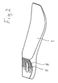
Figur 2- in schaubildlicher Darstellung die Fußinnenfeder
gemäß
Figur 1 jedoch in gegenüber derFigur 1 um 180° verdrehter Lage.
- Figure 1
- a vertical longitudinal section through a prosthetic foot part with attached prosthetic tube and
- Figure 2
- in a graphical representation, the inner foot spring according to FIG. 1, however, in a position rotated by 180 ° with respect to FIG. 1.
Das dargestellte Prothesenfußteil umfaßt im wesentlichen eine
sich vom Fersenbereich in den Vorfußbereich erstreckende Fußinnenfeder
1, die sich auf einem auswechselbaren Einlegekeil 2
abstützt, der formschlüssig zwischen der Fußinnenfeder 1 und
der Unterseite 3a einer Fußinnenfeder 1 und Einlegekeil 2 umschließenden
kosmetischen Verkleidung 3 gehalten ist. Letztere
kann als Schaumkosmetik, als Schaumkosmetik mit verstärkter
Sohle oder als Schuh bzw. Sandale ausgebildet sein. The prosthetic foot part shown comprises essentially one
inner spring extending from the heel area into the
Die Verbindung des Prothesenfußteils mit einem Prothesenrohr 4
einer Unterschenkelprothese erfolgt über einen Adapter 5 und
einen sich durch diesen hindurch erstreckenden Schraubbolzen
6.The connection of the prosthetic foot part with a prosthetic tube 4
a lower leg prosthesis takes place via an
Der Adapter 5 stützt sich mit seiner als Zylindersegment ausgebildeten
und mit einer Verzahnung 7 versehenen Unterseite
auf einer entsprechend ausgebildeten Anschlußfläche der Fußinnenfeder
1 ab, deren Verzahnung 8 formschlüssig in die Verzahnung
7 des Adapters 5 eingreift. Das obere Ende des Adapters
5 ist als Zapfen 9 ausgebildet, auf den das Prothesenrohr
4 gesteckt ist, das sich mit seinem unteren Ende auf einer
ringförmigen Anschlagfläche 10 des Adapters 5 abstützt. Der
Schraubbolzen 6 ist durch einen sich in Fußlängsrichtung erstreckenden,
eine dem Bolzendurchmesser d entsprechende Breite
b aufweisenden Schlitz 11 der Fußinnenfeder 1 gesteckt und
stützt sich mit seinem das untere Ende bildenden Bolzenkopf
über eine Scheibe 12 an der Unterseite 1a der Fußinnenfeder 1
ab, die in dem den Schlitz 11 umgebenden Bereich ebenfalls als
Zylindersegment ausgebildet ist, deren Kontur die Auflagefläche
der Scheibe 12 angepaßt ist.The
Das Prothesenrohr 4 umschließt zusammen mit dem Zapfen 9 des
Adapters 5 einen Ringspalt, der - gesehen von der Adapter-Anschlagfläche
10 nach oben - einen unteren, vorzugsweise aus
Kunststoff bestehenden Abschlußring 13, einen Elastomerring
14, einen Kunststoff-Zwischenring 15, einen weiteren Elastomerring
16 sowie einen oberen Kunststoff-Abschlußring 17 aufnimmt.
Letzterer wird von oben beaufschlagt von einem auf dem
Adapterzapfen 9 geführten, sich an der Innenwandung des aufgesteckten
Prothesenrohres 4 abstützenden Druckstück 18. Der
Schraubbolzen 6 ist mit seinem oberen Ende durch das Druckstück
18 sowie auf diesem aufliegende Tellerfedern 19 hindurchgesteckt
und mit einer Befestigungsmutter 20 bestückt,
die für die Tellerfedern 19 das zweite, dem Druckstück 18 gegenüberliegende
Widerlager bildet. Zwischen dem Druckstück 18
und der Befestigungsmutter 20 ist eine in der Zeichnung nicht
näher dargestellte Verdrehsicherung vorgesehen. Ferner ist
zwischen dem Druckstück 18 und dem Prothesenrohr 4 eine Verdrehsicherung
vorgesehen in Form eines dazwischen eingelegten
Elastomerringes 21.The prosthesis tube 4 encloses together with the
Nach dem (teilweise) Lösen des Schraubbolzens 6 besteht die
Möglichkeit, verschiedene Absatzhöhen durch Verschwenken des
Adapters 5 gegenüber der Fußinnenfeder 1 innerhalb der durch
den Schlitz 11 definierten lotrechten Ebene einzustellen. In
der gewünschten verschwenkten Stellung wird dann der Schraubbolzen
6 wieder angezogen, so daß die gewünschte Winkelstellung
über die ineinandergreifenden Verzahnungen 7, 8 formschlüssig
gesichert ist. Die für die Einstellung vorgenommene
Verschwenkung des Schraubbolzens 6 und damit des Adapters 5
erfolgt um eine gedachte horizontale Schwenkachse, die bei dem
Ausführungsbeispiel etwa im Bereich der Befestigungsmutter 20
liegt und senkrecht auf der Zeichenebene steht.After (partially) loosening the
Der Schraubbolzen 6 verbindet als zentrale Halterung alle Prothesenfußteile
miteinander und sichert deren Position in bezug
auf deren Verschiebbarkeit in Richtung der Beinlängsachse.
Gleichzeitig dient der Schraubbolzen 6 aber auch zum Aufbringen
der das aufgesteckte Prothesenrohr 4 kraftschlüssig mit
dem Adapterzapfen 9 verbindenden Kraft. Denn ein Anziehen des
Schraubbolzens 6 beaufschlagt das Druckstück 18 mit einer in
Bolzenlängsrichtung nach unten weisenden Kraft, durch die das
im Ringspalt zwischen Prothesenrohr 4 und Adapterzapfen 9 angeordnete
Ringpaket axial beaufschlagt wird. Diese Kraftbeaufschlagung
führt zu einer Verformung der Elastomerringe 14, 16,
die letztlich den genannten Kraftschluß hervorrufen. Hierdurch
wird das Prothesenrohr 4 gegenüber dem Adapterzapfen 9 hinsichtlich
der Längs- und Torsionskräfte gesichert. Zugleich
aber ergibt sich eine schnell und einfach lösbare Verbindung
zwischen dem Prothesenfußteil und dem Prothesenrohr 4. Das
durch die Tellerfedern 19 gebildete Federelement steuert -
ohne Verwendung eines Drehmomentenschlüssels - das notwendigerweise
aufzubringende Drehmoment zum Anziehen der Schraube. The
Vom Aufbau her kann das Prothesenfußteil links- und rechtsseitig verwendet werden.The prosthetic foot part can be constructed on the left and right sides be used.
Die Fußinnenfeder 1 dient zur Energiespeicherung beim Abrollen
und der dadurch bewirkten Biegung an dem sich verjüngenden
Ende gegenüber dem Adapter 5. Ein seitliches Verrutschen des
Adapters 5 wird durch die Formgebung des Schlitzes 11 verhindert.The
Der Einlegekeil 2 dient zum Anpassen des Fußteils an die Absatzhöhe;
durch entsprechende Wahl des Einlegekeils läßt sich
die Auftrittsdämpfung verändern. Die kosmetische Verkleidung 3
erlaubt eine einfache Anpassung an die Fußgröße.The
Das Prothesenrohr 4 dient zur Überleitung von Kräften entlang der Beinlängsachse auf das Prothesenfußteil; durch Kürzen des Prothesenrohres 4 ist in einfacher Weise eine individuelle Einstellung der Beinlänge möglich.The prosthesis tube 4 serves to transfer forces along the longitudinal axis of the leg on the prosthetic foot part; by shortening the Prosthetic tube 4 is an individual in a simple manner Leg length adjustment possible.
Claims (5)
- Joint-less prosthetic foot part with a foot internal tongue (1) which extends from the heel region into the metatarsal region, is surrounded by a cosmetic cladding (3) and is connected via a screw bolt (6) to an adapter (5) which has a clamping connection for the detachable connection of a prosthetic tube (4), comprising the following features:a) with its underside provided with a toothing (7) and formed as a cylinder segment, the adapter (5) is supported on a correspondingly formed connecting surface of the foot internal tongue (1), the toothing (8) of which positively engages into the toothing (7) of the adapter (5);b) the upper end of the adapter (5) is formed as peg (9) onto which the prosthetic tube (4) is placed;c) the screw bolt (6) is placed through a slit (11) of the foot internal tongue (1) extending in the longitudinal direction of the foot and having a width (b) corresponding to the bolt diameter (d) and with its lower end is supported on the underside (la) of the foot internal tongue (1) which is formed as a cylinder segment in the slit region also;d) the upper end of the screw bolt (6) extending beyond the adapter peg (9) acts upon the said clamping connection, which has a splaying element (14, 16) which is arranged in an annular gap between adapter peg (9) and prosthetic tube (4) and is acted upon by tightening the screw bolt (6) ;e) the splaying element has at least one elastomer ring (14, 16) which is supported with its underside directly or indirectly on a stop surface (10) of the adapter (5) and is acted upon on its upper side by a pressure piece (18) guided on the adapter peg (9), which pressure piece is acted upon in its turn by the screw bolt in the axial direction of the screw bolt (6).
- Prosthetic foot part according to Claim 1, characterized in that the elastomer ring (14, 16) is arranged between an intermediate and a terminal ring (15, 13, 17).
- Prosthetic foot part according to Claim 1 or 2, characterized in that the screw bolt (6) is supported on the pressure piece (18) by means of a spring element (19).
- Prosthetic foot part according to one of the preceding Claims, characterized in that the foot internal tongue (1) is supported on an interchangeable insert wedge (2) .
- Prosthetic foot part according to Claim 4, characterized in that the insert wedge (2) is positively held between the underside (3a) of the cosmetic cladding (3) and the foot internal tongue (1) .
Applications Claiming Priority (3)
| Application Number | Priority Date | Filing Date | Title |
|---|---|---|---|
| DE19521147 | 1995-06-09 | ||
| DE19521147A DE19521147C1 (en) | 1995-06-09 | 1995-06-09 | Articulated prosthetic foot part |
| PCT/DE1996/001031 WO1996041598A1 (en) | 1995-06-09 | 1996-06-05 | Jointless foot prosthesis |
Publications (2)
| Publication Number | Publication Date |
|---|---|
| EP0830117A1 EP0830117A1 (en) | 1998-03-25 |
| EP0830117B1 true EP0830117B1 (en) | 2000-03-08 |
Family
ID=7764059
Family Applications (1)
| Application Number | Title | Priority Date | Filing Date |
|---|---|---|---|
| EP96916002A Expired - Lifetime EP0830117B1 (en) | 1995-06-09 | 1996-06-05 | Jointless foot prosthesis |
Country Status (15)
| Country | Link |
|---|---|
| US (1) | US5888239A (en) |
| EP (1) | EP0830117B1 (en) |
| JP (1) | JPH11507282A (en) |
| CN (1) | CN1173812A (en) |
| AR (1) | AR002388A1 (en) |
| AU (1) | AU698110B2 (en) |
| BR (1) | BR9609199A (en) |
| DE (2) | DE19521147C1 (en) |
| ES (1) | ES2115570T1 (en) |
| PL (1) | PL181428B1 (en) |
| RU (1) | RU2151578C1 (en) |
| TR (1) | TR199701338T1 (en) |
| TW (1) | TW338720B (en) |
| WO (1) | WO1996041598A1 (en) |
| ZA (1) | ZA964843B (en) |
Families Citing this family (57)
| Publication number | Priority date | Publication date | Assignee | Title |
|---|---|---|---|---|
| US6206934B1 (en) * | 1998-04-10 | 2001-03-27 | Flex-Foot, Inc. | Ankle block with spring inserts |
| SE511893C2 (en) * | 1996-07-05 | 1999-12-13 | Pro Pel Ab | Customizable front foot portion for a foot prosthesis; use of such a front foot part in an adjustable foot prosthesis as well as systems for individually adaptable foot prostheses |
| DE19756635B4 (en) * | 1996-12-21 | 2005-12-15 | Knecht Maschinenbau Gmbh | Knife bolt for the rotationally fixed positioning of a cutter blade on a traction sheave |
| US6080197A (en) * | 1998-08-13 | 2000-06-27 | Teh Lin Prosthetic & Orthopaedic Inc. | Shock absorbing device for an artificial leg |
| FR2782262B1 (en) * | 1998-08-17 | 2001-02-09 | Michel Porte | TEST OR IMPLANTABLE COTYLE WITH ADJUSTABLE ORIENTATION |
| US6261324B1 (en) * | 1999-05-26 | 2001-07-17 | Crp, Inc. | Foot prosthesis |
| SE515958C2 (en) * | 1999-06-10 | 2001-11-05 | Gramtec Innovation Ab | Device for a leg prosthesis provided with a foot |
| EP1395209B1 (en) * | 2000-10-26 | 2010-06-23 | OSSUR North America, Inc. | Foot prosthesis having cushioned ankle |
| US7112340B2 (en) * | 2001-10-19 | 2006-09-26 | Baxter International Inc. | Compositions of and method for preparing stable particles in a frozen aqueous matrix |
| WO2004017872A1 (en) | 2002-08-22 | 2004-03-04 | Victhom Human Bionics Inc. | Actuated leg prosthesis for above-knee amputees |
| US7736394B2 (en) * | 2002-08-22 | 2010-06-15 | Victhom Human Bionics Inc. | Actuated prosthesis for amputees |
| US7097666B2 (en) * | 2003-07-25 | 2006-08-29 | American Prosthetic Components, Inc. | Device for angularly coupling prosthetic components |
| US20050027371A1 (en) * | 2003-08-01 | 2005-02-03 | Sen-Jung Chen | Artificial limb with relative position-adjustable upper and lower limb parts |
| US8007544B2 (en) * | 2003-08-15 | 2011-08-30 | Ossur Hf | Low profile prosthetic foot |
| US7815689B2 (en) | 2003-11-18 | 2010-10-19 | Victhom Human Bionics Inc. | Instrumented prosthetic foot |
| US20050107889A1 (en) | 2003-11-18 | 2005-05-19 | Stephane Bedard | Instrumented prosthetic foot |
| US20050137717A1 (en) * | 2003-12-18 | 2005-06-23 | Finn Gramnas | Prosthetic foot with rocker member |
| US20060184280A1 (en) * | 2005-02-16 | 2006-08-17 | Magnus Oddsson | System and method of synchronizing mechatronic devices |
| US7896927B2 (en) | 2004-02-12 | 2011-03-01 | össur hf. | Systems and methods for actuating a prosthetic ankle based on a relaxed position |
| US7431737B2 (en) * | 2004-02-12 | 2008-10-07 | össur hf. | System and method for motion-controlled foot unit |
| WO2005087144A2 (en) | 2004-03-10 | 2005-09-22 | össur hf | Control system and method for a prosthetic knee |
| US8128709B2 (en) * | 2004-05-28 | 2012-03-06 | össur hf | Functional foot cover |
| US7542876B2 (en) * | 2004-06-25 | 2009-06-02 | Johnson Controls Technology Company | Method of and apparatus for evaluating the performance of a control system |
| WO2006069264A1 (en) * | 2004-12-22 | 2006-06-29 | össur hf | Systems and methods for processing limb motion |
| US8048007B2 (en) | 2005-02-02 | 2011-11-01 | össur hf | Prosthetic and orthotic systems usable for rehabilitation |
| US8801802B2 (en) * | 2005-02-16 | 2014-08-12 | össur hf | System and method for data communication with a mechatronic device |
| SE528516C2 (en) | 2005-04-19 | 2006-12-05 | Lisa Gramnaes | Combined active and passive leg prosthesis system and a method for performing a movement cycle with such a system |
| DE102005031185A1 (en) * | 2005-07-01 | 2007-01-04 | Otto Bock Healthcare Ip Gmbh & Co. Kg | Orthopedic technical aid, in particular prosthesis for a limb |
| WO2007027808A2 (en) | 2005-09-01 | 2007-03-08 | össur hf | System and method for determining terrain transitions |
| US8048172B2 (en) | 2005-09-01 | 2011-11-01 | össur hf | Actuator assembly for prosthetic or orthotic joint |
| US7503937B2 (en) * | 2006-07-03 | 2009-03-17 | Ossur Hf | Prosthetic foot |
| CN101553191B (en) * | 2006-07-03 | 2013-03-13 | 奥苏尔公司 | Prosthetic foot |
| US7824446B2 (en) * | 2006-12-06 | 2010-11-02 | Freedom Innovations, Llc | Prosthetic foot with longer upper forefoot and shorter lower forefoot |
| US7727285B2 (en) * | 2007-01-30 | 2010-06-01 | Freedom Innovations, Llc | Prosthetic foot with variable medial/lateral stiffness |
| US11020248B2 (en) | 2007-09-19 | 2021-06-01 | Proteor USA, LLC | Vacuum system for a prosthetic foot |
| US10405998B2 (en) | 2007-09-19 | 2019-09-10 | Ability Dynamics Llc | Mounting bracket for connecting a prosthetic limb to a prosthetic foot |
| EP2257247B1 (en) | 2008-03-24 | 2018-04-25 | Ossur HF | Transfemoral prosthetic systems and methods for operating the same |
| US8685109B2 (en) * | 2008-07-01 | 2014-04-01 | össur hf | Smooth rollover insole for prosthetic foot |
| US9060884B2 (en) | 2011-05-03 | 2015-06-23 | Victhom Human Bionics Inc. | Impedance simulating motion controller for orthotic and prosthetic applications |
| EP2758009B1 (en) | 2011-09-20 | 2019-10-23 | Össur HF | Dorsi-plantar prosthetic ankle module |
| US8961618B2 (en) | 2011-12-29 | 2015-02-24 | össur hf | Prosthetic foot with resilient heel |
| US20130204397A1 (en) * | 2012-02-02 | 2013-08-08 | Elwin Isaac Nordman, JR. | Prosthetic foot covering enabling rapid conversion between shoe and barefoot walking |
| US9017419B1 (en) | 2012-03-09 | 2015-04-28 | össur hf | Linear actuator |
| EP2956094B1 (en) * | 2013-02-13 | 2017-10-11 | Össur hf | Overmould attachments for prosthetic foot |
| US9561118B2 (en) | 2013-02-26 | 2017-02-07 | össur hf | Prosthetic foot with enhanced stability and elastic energy return |
| DE102014006687A1 (en) * | 2014-05-09 | 2015-11-12 | Otto Bock Healthcare Gmbh | prosthetic |
| US20160175118A1 (en) * | 2014-12-18 | 2016-06-23 | Fountainhead, Llc | Prosthetic spacer devices, systems, and methods |
| EP3244841A4 (en) | 2015-01-15 | 2018-09-12 | Ability Dynamics, LLC | Prosthetic foot |
| CN105055053B (en) * | 2015-08-18 | 2017-06-13 | 陕西福音假肢有限责任公司 | Adjustable artificial limb anklebone joint |
| US9949850B2 (en) | 2015-09-18 | 2018-04-24 | Össur Iceland Ehf | Magnetic locking mechanism for prosthetic or orthotic joints |
| WO2018102609A1 (en) | 2016-12-01 | 2018-06-07 | Össur Iceland Ehf | Prosthetic feet having heel height adjustability |
| FR3063887B3 (en) * | 2017-03-17 | 2019-12-13 | Pm Ingenierie Et Design | FOOT-TO-BLADE PROSTHESIS |
| US10980648B1 (en) | 2017-09-15 | 2021-04-20 | Össur Iceland Ehf | Variable stiffness mechanism and limb support device incorporating the same |
| US11446164B1 (en) | 2017-09-15 | 2022-09-20 | Össur Iceland Ehf | Variable stiffness mechanisms |
| JP2021058318A (en) * | 2019-10-04 | 2021-04-15 | BionicM株式会社 | Foot part of artificial leg, and artificial leg |
| DE102019134984A1 (en) * | 2019-12-18 | 2021-06-24 | Ottobock Se & Co. Kgaa | Foot cosmetic system |
| DE102020120498B4 (en) * | 2020-08-04 | 2022-03-31 | Ottobock Se & Co. Kgaa | prosthetic foot |
Family Cites Families (10)
| Publication number | Priority date | Publication date | Assignee | Title |
|---|---|---|---|---|
| FR2148322B1 (en) * | 1971-07-22 | 1975-02-07 | Proteor Sa | |
| FR2410998A1 (en) * | 1977-12-08 | 1979-07-06 | Lebre Patrick | Tubular prosthesis adjusting mechanism - has wedge pieces and sliding plates with central locking screw fixed to coupling lug |
| GB2098072B (en) * | 1980-09-25 | 1984-03-21 | Blatchford & Sons Chas A Ltd | Improved endo-skeletal artificial limb |
| US4387472A (en) * | 1980-10-02 | 1983-06-14 | Medical Center Prosthetics, Inc. | Torque absorber with biofeedback |
| US4555817A (en) * | 1983-07-18 | 1985-12-03 | Mckendrick Roderick W | Prosthetic foot and ankle joint |
| US4645509A (en) * | 1984-06-11 | 1987-02-24 | Model & Instrument Development Corporation | Prosthetic foot having a cantilever spring keel |
| CA1305585C (en) * | 1986-07-28 | 1992-07-28 | Robert E. Arbogast | Prosthetic foot |
| US5112356A (en) * | 1988-03-04 | 1992-05-12 | Chas A. Blatchford & Sons Limited | Lower limb prosthesis with means for restricting dorsi-flexion |
| JPH01305803A (en) * | 1988-05-31 | 1989-12-11 | Daikin Ind Ltd | Purifying method for hydrochloric acid |
| DE4209974C1 (en) * | 1992-03-27 | 1993-04-15 | Otto Bock Orthopaedische Industrie Besitz- Und Verwaltungs-Kommanditgesellschaft, 3408 Duderstadt, De |
-
1995
- 1995-06-09 DE DE19521147A patent/DE19521147C1/en not_active Expired - Fee Related
-
1996
- 1996-06-05 RU RU97112184/14A patent/RU2151578C1/en active
- 1996-06-05 CN CN96191788A patent/CN1173812A/en active Pending
- 1996-06-05 DE DE59604607T patent/DE59604607D1/en not_active Expired - Fee Related
- 1996-06-05 ES ES96916002T patent/ES2115570T1/en active Pending
- 1996-06-05 WO PCT/DE1996/001031 patent/WO1996041598A1/en active IP Right Grant
- 1996-06-05 BR BR9609199A patent/BR9609199A/en not_active Application Discontinuation
- 1996-06-05 EP EP96916002A patent/EP0830117B1/en not_active Expired - Lifetime
- 1996-06-05 AU AU58923/96A patent/AU698110B2/en not_active Ceased
- 1996-06-05 TR TR97/01338T patent/TR199701338T1/en unknown
- 1996-06-05 PL PL96321658A patent/PL181428B1/en unknown
- 1996-06-05 JP JP9502497A patent/JPH11507282A/en active Pending
- 1996-06-05 US US08/894,693 patent/US5888239A/en not_active Expired - Fee Related
- 1996-06-07 ZA ZA964843A patent/ZA964843B/en unknown
- 1996-06-07 AR ARP960103031A patent/AR002388A1/en active IP Right Grant
- 1996-07-18 TW TW085106765A patent/TW338720B/en active
Also Published As
| Publication number | Publication date |
|---|---|
| WO1996041598A1 (en) | 1996-12-27 |
| ES2115570T1 (en) | 1998-07-01 |
| AU5892396A (en) | 1997-01-09 |
| DE59604607D1 (en) | 2000-04-13 |
| JPH11507282A (en) | 1999-06-29 |
| AU698110B2 (en) | 1998-10-22 |
| PL321658A1 (en) | 1997-12-22 |
| TW338720B (en) | 1998-08-21 |
| PL181428B1 (en) | 2001-07-31 |
| CN1173812A (en) | 1998-02-18 |
| ZA964843B (en) | 1997-01-07 |
| AR002388A1 (en) | 1998-03-11 |
| TR199701338T1 (en) | 1998-02-21 |
| BR9609199A (en) | 1999-05-11 |
| US5888239A (en) | 1999-03-30 |
| RU2151578C1 (en) | 2000-06-27 |
| EP0830117A1 (en) | 1998-03-25 |
| DE19521147C1 (en) | 1996-12-05 |
Similar Documents
| Publication | Publication Date | Title |
|---|---|---|
| EP0830117B1 (en) | Jointless foot prosthesis | |
| EP0938872B1 (en) | Pivotable attachment system for a bone screw | |
| EP0011258B1 (en) | Device for the external fixation of the fragments of a broken bone | |
| EP0243298B1 (en) | Construction kit for a stem prosthesis | |
| DE3245330C2 (en) | Artificial body part | |
| DE2605644C3 (en) | Lockable prosthetic joint | |
| DE3104353A1 (en) | JOINT TRIPOD | |
| EP0603114A1 (en) | Clamping device | |
| WO1992020298A1 (en) | Implant with pressure surface | |
| DE3837228A1 (en) | DEVICE FOR EXTERNAL DETERMINATION OF BONE FRAGMENTS | |
| DE3441417C1 (en) | Horse hoof shoe | |
| EP0260671B1 (en) | Racket, especially for tennis, and a device for stringing it | |
| DE2726963C3 (en) | Device for pulling off a cylinder part from a screw extruder | |
| DE2433358C2 (en) | Dental attachment for the detachable attachment of dentures to the rest of the dentition | |
| DE102012012173B4 (en) | Device for adjusting a prosthetic leg and method for creating such a device | |
| EP0564889A1 (en) | Connecting device, in particular for a tubular member | |
| EP0298909B1 (en) | Extracoronal activatable slide attachment | |
| EP2491888B1 (en) | Anchoring device for fixing orthodontic wires for a corrective orthodontic device | |
| EP0937546B1 (en) | Clamping and separating device, especially device for pulling off bearings | |
| DE4139700A1 (en) | Surgical bone fragment anchor ball joints - has recesses across faces of T-shaped top jaw and vertical bottom jaw, for securing anchorage screws | |
| EP0893057B1 (en) | Open plastic horseshoe | |
| DE2507468A1 (en) | Fully adjustable athletic starting block - moves forward backwards and in width with tiltable block surfaces | |
| EP0236551B1 (en) | Centrifuge | |
| EP0215771A2 (en) | Foldable walking-stick | |
| DE3203031A1 (en) | Variable length adjusting rod |
Legal Events
| Date | Code | Title | Description |
|---|---|---|---|
| PUAI | Public reference made under article 153(3) epc to a published international application that has entered the european phase |
Free format text: ORIGINAL CODE: 0009012 |
|
| 17P | Request for examination filed |
Effective date: 19970710 |
|
| AK | Designated contracting states |
Kind code of ref document: A1 Designated state(s): DE ES FR GB IT |
|
| ITCL | It: translation for ep claims filed |
Representative=s name: MODIANO & ASSOCIATI S.R.L. |
|
| GBC | Gb: translation of claims filed (gb section 78(7)/1977) | ||
| EL | Fr: translation of claims filed | ||
| REG | Reference to a national code |
Ref country code: ES Ref legal event code: BA2A Ref document number: 2115570 Country of ref document: ES Kind code of ref document: T1 |
|
| GRAG | Despatch of communication of intention to grant |
Free format text: ORIGINAL CODE: EPIDOS AGRA |
|
| GRAG | Despatch of communication of intention to grant |
Free format text: ORIGINAL CODE: EPIDOS AGRA |
|
| GRAH | Despatch of communication of intention to grant a patent |
Free format text: ORIGINAL CODE: EPIDOS IGRA |
|
| 17Q | First examination report despatched |
Effective date: 19990811 |
|
| GRAH | Despatch of communication of intention to grant a patent |
Free format text: ORIGINAL CODE: EPIDOS IGRA |
|
| GRAA | (expected) grant |
Free format text: ORIGINAL CODE: 0009210 |
|
| AK | Designated contracting states |
Kind code of ref document: B1 Designated state(s): DE ES FR GB IT |
|
| PG25 | Lapsed in a contracting state [announced via postgrant information from national office to epo] |
Ref country code: IT Free format text: LAPSE BECAUSE OF FAILURE TO SUBMIT A TRANSLATION OF THE DESCRIPTION OR TO PAY THE FEE WITHIN THE PRE;WARNING: LAPSES OF ITALIAN PATENTS WITH EFFECTIVE DATE BEFORE 2007 MAY HAVE OCCURRED AT ANY TIME BEFORE 2007. THE CORRECT EFFECTIVE DATE MAY BE DIFFERENT FROM THE ONE RECORDED.SCRIBED TIME-LIMIT Effective date: 20000308 |
|
| REF | Corresponds to: |
Ref document number: 59604607 Country of ref document: DE Date of ref document: 20000413 |
|
| GBT | Gb: translation of ep patent filed (gb section 77(6)(a)/1977) |
Effective date: 20000330 |
|
| ET | Fr: translation filed | ||
| PG25 | Lapsed in a contracting state [announced via postgrant information from national office to epo] |
Ref country code: ES Free format text: LAPSE BECAUSE OF FAILURE TO SUBMIT A TRANSLATION OF THE DESCRIPTION OR TO PAY THE FEE WITHIN THE PRESCRIBED TIME-LIMIT Effective date: 20000919 |
|
| PLBE | No opposition filed within time limit |
Free format text: ORIGINAL CODE: 0009261 |
|
| STAA | Information on the status of an ep patent application or granted ep patent |
Free format text: STATUS: NO OPPOSITION FILED WITHIN TIME LIMIT |
|
| 26N | No opposition filed | ||
| PGFP | Annual fee paid to national office [announced via postgrant information from national office to epo] |
Ref country code: DE Payment date: 20010615 Year of fee payment: 6 |
|
| PGFP | Annual fee paid to national office [announced via postgrant information from national office to epo] |
Ref country code: FR Payment date: 20010628 Year of fee payment: 6 |
|
| REG | Reference to a national code |
Ref country code: GB Ref legal event code: IF02 |
|
| PGFP | Annual fee paid to national office [announced via postgrant information from national office to epo] |
Ref country code: GB Payment date: 20020522 Year of fee payment: 7 |
|
| PG25 | Lapsed in a contracting state [announced via postgrant information from national office to epo] |
Ref country code: DE Free format text: LAPSE BECAUSE OF NON-PAYMENT OF DUE FEES Effective date: 20030101 |
|
| PG25 | Lapsed in a contracting state [announced via postgrant information from national office to epo] |
Ref country code: FR Free format text: LAPSE BECAUSE OF NON-PAYMENT OF DUE FEES Effective date: 20030228 |
|
| REG | Reference to a national code |
Ref country code: FR Ref legal event code: ST |
|
| PG25 | Lapsed in a contracting state [announced via postgrant information from national office to epo] |
Ref country code: GB Free format text: LAPSE BECAUSE OF NON-PAYMENT OF DUE FEES Effective date: 20030605 |
|
| GBPC | Gb: european patent ceased through non-payment of renewal fee |
Effective date: 20030605 |