EP0814397B1 - Portable board computer system with control units for working machines - Google Patents
Portable board computer system with control units for working machines Download PDFInfo
- Publication number
- EP0814397B1 EP0814397B1 EP97107757A EP97107757A EP0814397B1 EP 0814397 B1 EP0814397 B1 EP 0814397B1 EP 97107757 A EP97107757 A EP 97107757A EP 97107757 A EP97107757 A EP 97107757A EP 0814397 B1 EP0814397 B1 EP 0814397B1
- Authority
- EP
- European Patent Office
- Prior art keywords
- board computer
- computer system
- portable case
- display
- working machine
- Prior art date
- Legal status (The legal status is an assumption and is not a legal conclusion. Google has not performed a legal analysis and makes no representation as to the accuracy of the status listed.)
- Revoked
Links
- 238000003032 molecular docking Methods 0.000 claims description 24
- 238000004891 communication Methods 0.000 claims description 14
- 230000006870 function Effects 0.000 claims description 11
- 238000003780 insertion Methods 0.000 claims description 4
- 230000037431 insertion Effects 0.000 claims description 4
- 230000005540 biological transmission Effects 0.000 claims description 3
- 238000013500 data storage Methods 0.000 claims description 3
- 230000015654 memory Effects 0.000 claims description 3
- 230000003936 working memory Effects 0.000 claims 1
- 238000009434 installation Methods 0.000 description 2
- 238000000034 method Methods 0.000 description 2
- 230000007935 neutral effect Effects 0.000 description 2
- 238000003825 pressing Methods 0.000 description 2
- 230000002411 adverse Effects 0.000 description 1
- 230000000712 assembly Effects 0.000 description 1
- 238000000429 assembly Methods 0.000 description 1
- 150000001875 compounds Chemical class 0.000 description 1
- 238000013461 design Methods 0.000 description 1
- 238000007689 inspection Methods 0.000 description 1
- 230000003993 interaction Effects 0.000 description 1
- 238000012545 processing Methods 0.000 description 1
Images

Classifications
-
- B—PERFORMING OPERATIONS; TRANSPORTING
- B60—VEHICLES IN GENERAL
- B60R—VEHICLES, VEHICLE FITTINGS, OR VEHICLE PARTS, NOT OTHERWISE PROVIDED FOR
- B60R16/00—Electric or fluid circuits specially adapted for vehicles and not otherwise provided for; Arrangement of elements of electric or fluid circuits specially adapted for vehicles and not otherwise provided for
- B60R16/02—Electric or fluid circuits specially adapted for vehicles and not otherwise provided for; Arrangement of elements of electric or fluid circuits specially adapted for vehicles and not otherwise provided for electric constitutive elements
-
- A—HUMAN NECESSITIES
- A01—AGRICULTURE; FORESTRY; ANIMAL HUSBANDRY; HUNTING; TRAPPING; FISHING
- A01B—SOIL WORKING IN AGRICULTURE OR FORESTRY; PARTS, DETAILS, OR ACCESSORIES OF AGRICULTURAL MACHINES OR IMPLEMENTS, IN GENERAL
- A01B79/00—Methods for working soil
- A01B79/005—Precision agriculture
-
- G—PHYSICS
- G05—CONTROLLING; REGULATING
- G05B—CONTROL OR REGULATING SYSTEMS IN GENERAL; FUNCTIONAL ELEMENTS OF SUCH SYSTEMS; MONITORING OR TESTING ARRANGEMENTS FOR SUCH SYSTEMS OR ELEMENTS
- G05B19/00—Programme-control systems
- G05B19/02—Programme-control systems electric
- G05B19/04—Programme control other than numerical control, i.e. in sequence controllers or logic controllers
- G05B19/042—Programme control other than numerical control, i.e. in sequence controllers or logic controllers using digital processors
- G05B19/0426—Programming the control sequence
-
- G—PHYSICS
- G05—CONTROLLING; REGULATING
- G05B—CONTROL OR REGULATING SYSTEMS IN GENERAL; FUNCTIONAL ELEMENTS OF SUCH SYSTEMS; MONITORING OR TESTING ARRANGEMENTS FOR SUCH SYSTEMS OR ELEMENTS
- G05B19/00—Programme-control systems
- G05B19/02—Programme-control systems electric
- G05B19/18—Numerical control [NC], i.e. automatically operating machines, in particular machine tools, e.g. in a manufacturing environment, so as to execute positioning, movement or co-ordinated operations by means of programme data in numerical form
- G05B19/409—Numerical control [NC], i.e. automatically operating machines, in particular machine tools, e.g. in a manufacturing environment, so as to execute positioning, movement or co-ordinated operations by means of programme data in numerical form characterised by using manual data input [MDI] or by using control panel, e.g. controlling functions with the panel; characterised by control panel details or by setting parameters
-
- G—PHYSICS
- G06—COMPUTING; CALCULATING OR COUNTING
- G06F—ELECTRIC DIGITAL DATA PROCESSING
- G06F1/00—Details not covered by groups G06F3/00 - G06F13/00 and G06F21/00
- G06F1/16—Constructional details or arrangements
- G06F1/1613—Constructional details or arrangements for portable computers
- G06F1/1632—External expansion units, e.g. docking stations
-
- G—PHYSICS
- G05—CONTROLLING; REGULATING
- G05B—CONTROL OR REGULATING SYSTEMS IN GENERAL; FUNCTIONAL ELEMENTS OF SUCH SYSTEMS; MONITORING OR TESTING ARRANGEMENTS FOR SUCH SYSTEMS OR ELEMENTS
- G05B2219/00—Program-control systems
- G05B2219/20—Pc systems
- G05B2219/23—Pc programming
- G05B2219/23414—Pc as detachable program, debug, monitor device for control system
-
- G—PHYSICS
- G05—CONTROLLING; REGULATING
- G05B—CONTROL OR REGULATING SYSTEMS IN GENERAL; FUNCTIONAL ELEMENTS OF SUCH SYSTEMS; MONITORING OR TESTING ARRANGEMENTS FOR SUCH SYSTEMS OR ELEMENTS
- G05B2219/00—Program-control systems
- G05B2219/30—Nc systems
- G05B2219/36—Nc in input of data, input key till input tape
- G05B2219/36159—Detachable or portable programming unit, display, pc, pda
Definitions
- the invention relates to a mobile on-board computer system with operating units for working machines, the work machine being adjustable, controllable and / or controllable via the on-board computer system by means of the set values stored and / or entered in the on-board computer system and the data stored in the on-board computer system can be supplemented and / or changed via input devices and a replaceable control panel that includes display and input devices.
- Such a generic on-board computer system is for example from the DE 40 16 603 known. Although such an on-board computer system allows improved control and control of the machine equipped with it, but it has the disadvantage that it is relatively expensive.
- an on-board computer system allows improved control and control of the machine equipped with it, but it has the disadvantage that it is relatively expensive.
- the DE 36 12 767 discloses a remote control device consisting of a command generator, a coding device, a transmission path, a decoding device and a switching level.
- the interaction of these elements enables the transmission of machine-specific signals from a tractor to a working machine adapted thereto.
- individual elements such as the encoder and decoder can be removed and used on other machines here, but the commander and the switching level on the tractor are applicable only to the respective machine.
- a universal mobile application possibility on each type of machine is just not possible, but would have to be purchased and used separately for different machine types, the respective command generator and switching levels. This increases the cost and also the confusion due to the increasing number of different elements within the machine. Thus, the driver must always familiarize himself with new switching levels. It is therefore not possible to simply insert a complete system to ensure the readiness of different machines.
- the object of the invention is achieved by the on-board computer system installed in a portable case, the portable case with the working machine detachably connected and the portable case can be mounted on various machines.
- the inventive arrangement of an on-board computer system this can be easily dismantled from a machine and built on another machine, such as a farm tractor on a telescopic loader, from there on a SUV, in the office or for inspection on the field in a holding belt.
- a complete on-board computer system including a central computer unit with control and display part and possibly associated software and possibly other components by the features of the invention is easily replaceable, it can be used for several machines, making a significant cost reduction is possible for the machine user.
- the on-board computer system should have at least one flat screen display device to be adaptable to the displays in various work machines.
- the on-board computer system can be equipped with different components.
- one or more communication units, navigation / position determination units, and / or data storage units can be permanently or interchangeably installed in the portable casing.
- the connection and installation of the additional modules can be done via standardized interfaces (for example PCMCIA slots) and slots for the module housing.
- a communication unit for example, several different modems for different communication methods, such as Modacom, GSM, radio service, etc., be exchanged and used.
- a data storage unit for example, floppy or CD-ROM drives, magnetic card reader or PCMCIA cards can be used modularly interchangeable.
- the accumulated data can also be saved or read in online or alternatively online by third-party data stores via telecommunication means.
- one or more external operating units can be connected to the on-board computer system, such as a joystick, a multi-function handle or a keyboard.
- the operating options can be extended beyond the extent made possible by the on-board computer system installed in the portable casing.
- intelligent software between the external operating unit and on-board computer system it is possible that, for example, operating functions of the external operating unit can be learned or there is an active feedback of the state of a switched work machine unit.
- the portable case should be constructed so that additional units are modular on with the least possible effort on, on and off. Due to the modular structure, it is possible to use more sophisticated on-board computer units, for example, equipped with navigation systems on-board computer on different machines on which just the navigation function is needed. For this purpose, either the complete portable case is replaced, or the navigation modules are plugged into the portable case of the other work machine. Such an exchange is of course possible with or because of other module modules.
- the on-board computer system is placed in the portable case on a fixedly connected to the machine docking station.
- the docking station can be firmly connected via an additional holder with the working machine.
- On the machine can also be provided an insertion or storage compartment into which the portable case can be inserted or adjusted.
- the connections between the on-board computer system and the working machine can be produced via plug contacts which are located on the portable casing on the one hand and the docking station or the insertion or adjustment compartment on the other hand and which can be connected to one another by inserting or adjusting the portable casing in the working position.
- the docking station itself as a terminal unit may contain other modules, for example, RAM and / or ROM memory, plug contacts for machine interfacing, electronics for detecting and Vorauslus of electrical signals, warning horns, printers, standardized interfaces or connection options for handheld scanner. Also, in a docking station arranged in the EEPROM or EPROM a specific machine identifier for certain calibration values, settings, etc. may be stored. In addition, the portable case with the on-board computer and possibly other modules via standardized interfaces and connectors for connecting other devices to the on-board computer or the additional modules have.
- the versatile applicability of a built-in portable case on-board computer system is made possible by at least partially display images are displayed on the display devices of the on-board computer system containing specific elements of that machine with which the onboard computer system is currently connected.
- the work machine-specific functionality is thus achieved via at least partially work machine-specific display images.
- Individual or multiple functional states of the machine to be controlled by the on-board computer as a whole or in assemblies can be graphically displayed on at least one display device of the on-board computer system, for example via pictograms or a pictorial representation of the working machine that the functional or switching state is optically recognizable.
- one or more of the display images of a display device of the on-board computer system may be stored in the terminal and selected via a display menu or a communication of the onboard computer system with the docking station or the electronics of the work machine.
- one or more of the display images of a display device of the on-board computer system may be stored in the docking station or elsewhere of the work machine and via an automated or menu-driven communication of the onboard computer system with the docking station or downstream electronic elements of the work machine after docking in the Main memory of the on-board computer system is loaded.
- the on-board computer system compares the current statement value of one or more display images of a display device of the onboard computer system with the respective actual state of the displayed function of the work machine via a data bus system and corrects for deviations between the meaningfulness of the display image and the actual state of the displayed function Significance of the display image.
- Such a comparison can be made by a suitable software that evaluates the signals of a corresponding sensor.
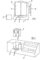
- FIG. 1 the schematic structure of an on-board computer system according to the invention can be seen.
- the computer unit A and the communication unit B are arranged.
- plugs 4 which must be plugged into the connector 6 located at the docking station C in order to establish a connection between the portable case 2 and the docking station C.
- the docking station C is in turn connected to the vehicle mount E.
- the portable case 2 the computer unit A or the communication unit B can additionally be connected to a control unit D, depending on which function the control unit D has and to which module it is usefully connected.
- FIG. 2 is a control panel 8 can be seen in a Einstellfach 10 is located, which fits to the dimensions of the portable case of the on-board computer system approximately.
- An operator console 8 may be present on a combine harvester, tractor, or other work machine.
- Well recognizable are the terminal base 12, to which corresponding counterparts are located on the underside of the portable case 2 of the on-board computer system and which fall into operative connection with each other when adjusting the portable case 2 in the adjustment compartment 10.
- the portable case 2 a clamp or similar device that prevents unintentional release of the connection to the plug contacts.
- FIG. 3 is a possible user interface of a computer unit A with control and display units shown in a portable case 2, which is assembled with a communication unit B and attached to a docking station C.
- control buttons 16 which usually correspond to a display image of the flat panel 14 and switch a function of an associated work machine assigned to the flat screen in the display image of an operating button.
- Keys are arranged in the control panel 18 which the machine user can use for menu guidance in the display screen of the flat screen 14 and for inputting commands or data.
- the user interface is generic and does not contain any machine-specific keyboard labels. The work machine-specific user interfaces are created only when the neutral keyboard of the user interface interacts with the work machine-specific display images of the flat screen 14.
- FIG. 4 shows an exemplary work machine-specific display image of the flat panel display 14.
- the display image 20 shows a round baler 26 with a round bale just ejected 28 that is currently controlled by the onboard computer system.
- symbolic representations 22 On the left side of the display image 20 are symbolic representations 22, which represent certain menu commands that are executed by pressing the next adjacent to the respective symbol fields buttons 16 of the control panel of the software and generate new menu images.
- symbolic representations 24 On the right side of the display image 20 are symbolic representations 24, with which by pressing the adjacent to the respective symbol fields adjacent buttons 16 of the control panel, the symbolically indicated functions of the machine are switched on or off, for example, the cutting device of the round baler, the yarn or network binding , the bale ejection or other functions.
- the display image 20 shown here is only an example, it can also be chosen completely different with different symbolism and spatial arrangement.
- the display devices of an on-board computer system can also display machine-independent data, for example when the on-board computer system is used as a laptop with word processing, spreadsheets and graphics and a display device serves as a screen for the laptop or if via the Display device, the processes of communication of the communication unit B with external communication partners or communicated files are displayed.
Landscapes
- Engineering & Computer Science (AREA)
- Physics & Mathematics (AREA)
- General Physics & Mathematics (AREA)
- Life Sciences & Earth Sciences (AREA)
- Mechanical Engineering (AREA)
- Theoretical Computer Science (AREA)
- Human Computer Interaction (AREA)
- Automation & Control Theory (AREA)
- Computer Hardware Design (AREA)
- Environmental Sciences (AREA)
- General Engineering & Computer Science (AREA)
- Soil Sciences (AREA)
- Manufacturing & Machinery (AREA)
- Digital Computer Display Output (AREA)
- Testing And Monitoring For Control Systems (AREA)
- Supply And Installment Of Electrical Components (AREA)
- Control By Computers (AREA)
- Numerical Control (AREA)
Description
Die Erfindung betrifft ein mobiles Bordcomputersystem mit Bedieneinheiten für Arbeitsmaschinen, wobei über das Bordcomputersystem die Arbeitsmaschine mittels der im Bordcomputersystem eingespeicherten und/oder eingegebenen Einstellwerte einstell-, steuer- und/oder regelbar ist und die im Bordcomputersystem eingespeicherten Daten über Eingabevorrichtungen ergänz- und oder veränderbar sind, sowie einer austauschbaren Bedienplatte, die Anzeige- und Eingabevorrichtungen aufweiset.The invention relates to a mobile on-board computer system with operating units for working machines, the work machine being adjustable, controllable and / or controllable via the on-board computer system by means of the set values stored and / or entered in the on-board computer system and the data stored in the on-board computer system can be supplemented and / or changed via input devices and a replaceable control panel that includes display and input devices.
Ein solches gattungsgemäßes Bordcomputersystem ist beispielsweise aus der
Demgemäß ist es die Aufgabe der vorliegenden Erfindung, ein Bordcomputersystem zu schaffen, das möglichst auf einer Vielzahl von Arbeitsmaschinen einsetzbar ist und dadurch eine Kostenentlastung der Maschinennutzer ermöglicht.Accordingly, it is the object of the present invention to provide an on-board computer system create, which is possible to use on a variety of machines and thereby allows a cost reduction of the machine users.
Die erfindungsgemäße Aufgabe wird gelöst, indem das Bordcomputersytem in einer tragbaren Hülle eingebaut, die tragbare Hülle mit der Arbeitsmaschine lösbar verbunden und die tragbare Hülle auf verschiedenen Arbeitsmaschinen montierbar ist. Durch die erfindungsgemäße Anordnung eines Bordcomputersystems kann dieses leicht von einer Maschine abgebaut und auf einer anderen Maschine aufgebaut werden, beispielsweise von einem Ackerschlepper auf einen Teleskoplader, von dort auf einen Geländewagen, ins Büro oder auch für Kontrollgänge auf dem Feld in einem Haltegürtel. Dadurch, daß ein komplettes Bordcomputersystem einschließlich einer zentralen Rechnereinheit mit Bedien- und Anzeigeteil und eventuell mit zugehöriger Software und möglicherweise anderen Komponenten durch die erfindungsgemäßen Merkmale leicht austauschbar ist, kann es für mehrere Arbeitsmaschinen eingesetzt werden, wodurch für den Maschinennutzer eine spürbare Kostenentlastung möglich wird.The object of the invention is achieved by the on-board computer system installed in a portable case, the portable case with the working machine detachably connected and the portable case can be mounted on various machines. The inventive arrangement of an on-board computer system, this can be easily dismantled from a machine and built on another machine, such as a farm tractor on a telescopic loader, from there on a SUV, in the office or for inspection on the field in a holding belt. Characterized in that a complete on-board computer system including a central computer unit with control and display part and possibly associated software and possibly other components by the features of the invention is easily replaceable, it can be used for several machines, making a significant cost reduction is possible for the machine user.
Das Bordcomputersystem sollte über zumindest einen Flachbildschirm als Anzeigevorrichtung verfügen, um für die Anzeigen in verschiedenen Arbeitsmaschinen anpaßbar zu sein. Das Bordcomputersystem kann mit unterschiedlichen Komponenten ausgestattet sein. Zusätzlich zur Recheneinheit mit Bedien- und Anzeigeteil können zusätzlich beispielsweise eine oder mehrere Kommunikationseinheiten, Navigations-/Positionsermittlungseinheiten, und oder Datenspeichereinheiten fest oder austauschbar in der tragbaren Hülle eingebaut sein. Der Anschluß und Einbau der zusätzlichen Module kann über genormte Schnittstellen (beispielsweise PCMCIA-Slots) und Einschubfächer für die Modulgehäuse erfolgen. Für eine Kommunikationseinheit können beispielsweise mehrere unterschiedliche Modems für unterschiedliche Kommunikationsverfahren, wie beispielsweise Modacom, GSM, Betriebsfunk etc. austausch- und einsetzbar sein. Als Datenspeichereinheit können beispielsweise Disketten- oder CD-ROM-Laufwerke, Magnetkartenleser oder PCMCIA-Karten modular austauschbar eingesetzt werden. Die anfallenden Daten können jedoch auch alternativ oder additiv online von Dritten Datenspeichern über Telekommunikationsmittel abgesichert abgespeichert oder eingelesen werden. Zudem können an das Bordcomputersystem ein oder mehrere externe Bedieneinheiten angeschlossen werden, wie beispielsweise ein Joystick, ein Multifunktionsgriff oder eine Tastatur. Durch solche externe Bedieneinheiten können die Bedienmöglichkeiten über den durch das in der tragbaren Hülle eingebaute Bordcomputersystem ermöglichte Maß hinaus erweitert werden. Durch eine intelligente Software zwischen externer Bedieneinheit und Bordcomputersystem ist es möglich, daß beispielsweise Bedienfunktionen der externen Bedieneinheit gelernt werden können oder es eine aktive Rückmeldung des Zustandes einer geschalteten Arbeitsmaschineneinheit gibt. Insgesamt sollte die tragbare Hülle so aufgebaut sein, daß zusätzliche Einheiten modular mit möglichst geringem Aufwand ein-, an- und ausbaubar sind. Durch den modularen Aufbau ist es möglich, aufwendiger ausgestattete Bordcomputereinheiten, beispielsweise mit Navigationssystemen ausgestattete Bordcomputer, auf unterschiedlichen Maschinen zu nutzen, auf denen gerade die Navigationsfunktion benötigt wird. Dazu wird dann entweder die komplette tragbare Hülle ausgetauscht, oder die Navigationsmodule werden in die tragbare Hülle der anderen Arbeitsmaschine eingesteckt. Ein solcher Austausch ist selbstverständlich auch mit oder wegen anderer Modulbausteine möglich.The on-board computer system should have at least one flat screen display device to be adaptable to the displays in various work machines. The on-board computer system can be equipped with different components. In addition to the arithmetic unit with control and display part, for example, one or more communication units, navigation / position determination units, and / or data storage units can be permanently or interchangeably installed in the portable casing. The connection and installation of the additional modules can be done via standardized interfaces (for example PCMCIA slots) and slots for the module housing. For a communication unit, for example, several different modems for different communication methods, such as Modacom, GSM, radio service, etc., be exchanged and used. As a data storage unit, for example, floppy or CD-ROM drives, magnetic card reader or PCMCIA cards can be used modularly interchangeable. However, the accumulated data can also be saved or read in online or alternatively online by third-party data stores via telecommunication means. In addition, one or more external operating units can be connected to the on-board computer system, such as a joystick, a multi-function handle or a keyboard. By means of such external operating units, the operating options can be extended beyond the extent made possible by the on-board computer system installed in the portable casing. By intelligent software between the external operating unit and on-board computer system, it is possible that, for example, operating functions of the external operating unit can be learned or there is an active feedback of the state of a switched work machine unit. Overall, the portable case should be constructed so that additional units are modular on with the least possible effort on, on and off. Due to the modular structure, it is possible to use more sophisticated on-board computer units, for example, equipped with navigation systems on-board computer on different machines on which just the navigation function is needed. For this purpose, either the complete portable case is replaced, or the navigation modules are plugged into the portable case of the other work machine. Such an exchange is of course possible with or because of other module modules.
Bevorzugt wird das Bordcomputersystem in der tragbaren Hülle auf eine mit der Arbeitsmaschine fest verbundene Dockingstation aufgesetzt. Die Dockingstation kann über einen zusätzlichen Halter mit der Arbeitsmaschine fest verbunden sein. Auf der Arbeitsmaschine kann auch ein Einschub- oder Stellfach vorgesehen sein, in das die tragbare Hülle einschieb- oder einstellbar ist. Die Anschlüsse zwischen dem Bordcomputersystem und der Arbeitsmaschine sind über Steckkontakte herstellbar, die sich an der tragbaren Hülle einerseits und der Dockingstation oder dem Einschub- oder Einstellfach andererseits befinden und welche durch Einschieben oder Einstellen der tragbaren Hülle in die Arbeitsposition miteinander verbindbar sind. Die Dockingstation selbst als Anschlußeinheit kann weitere Baugruppen enthalten, beispielsweise RAM- und/oder ROM-Speicher, Steckkontakte für die Maschinenanbindung, Elektronik zum Erfassen und Vorauswerten von elektrischen Signalen, Warnhupen, Drucker, genormte Schnittstellen oder auch Anschlußmöglichkeiten für Handscanner. Auch kann in einem in der Dockingstation angeordneten EEPROM oder EPROM eine bestimmte Maschinenkennung für bestimmte Kalibrierwerte, Einstellgrößen etc. abgelegt sein. Zusätzlich kann auch die tragbare Hülle mit dem Bordcomputer und eventuell noch weiteren Modulen über genormte Schnittstellen und Anschlußstecker zum Anschluß von weiteren Geräten an den Bordcomputer oder die zusätzlichen Module verfügen.Preferably, the on-board computer system is placed in the portable case on a fixedly connected to the machine docking station. The docking station can be firmly connected via an additional holder with the working machine. On the machine can also be provided an insertion or storage compartment into which the portable case can be inserted or adjusted. The connections between the on-board computer system and the working machine can be produced via plug contacts which are located on the portable casing on the one hand and the docking station or the insertion or adjustment compartment on the other hand and which can be connected to one another by inserting or adjusting the portable casing in the working position. The docking station itself as a terminal unit may contain other modules, for example, RAM and / or ROM memory, plug contacts for machine interfacing, electronics for detecting and Vorauswerte of electrical signals, warning horns, printers, standardized interfaces or connection options for handheld scanner. Also, in a docking station arranged in the EEPROM or EPROM a specific machine identifier for certain calibration values, settings, etc. may be stored. In addition, the portable case with the on-board computer and possibly other modules via standardized interfaces and connectors for connecting other devices to the on-board computer or the additional modules have.
Die vielseitige Einsetzbarkeit eines in einer tragbaren Hülle eingebauten Bordcomputersystems wird erst ermöglicht, indem auf den Anzeigevorrichtungen des Bordcomputersystems zumindest teilweise Anzeigebilder darstellbar sind, die spezifische Elemente derjenigen Maschine enthalten, mit der das Bordcomputersystem aktuell verbunden ist. Neben einer neutralen Ausgestaltung der Bedienelemente des Bordcomputersystems wird die arbeitsmaschinenindividuelle Funktionalität also über zumindest teilweise arbeitsmaschinenspezifische Anzeigebilder erreicht. Einzelne oder mehrere Funktionszustände der vom Bordcomputer zu steuernden Maschine im Ganzen oder in Baugruppen können auf zumindest einer Anzeigevorrichtung des Bordcomputersystems graphisch so dargestellt werden, beispielsweise über Piktogramme oder eine bildliche Darstellung der Arbeitsmaschine, daß der Funktions- oder Schaltzustand optisch erkennbar ist. Um die jeweiligen Anzeigebilder verfügbar zu haben, können eines oder mehrere der Anzeigebilder einer Anzeigevorrichtung des Bordcomputersystems im Terminal gespeichert sein und über ein Anzeigemenue oder eine Kommunikation des Bordcomputersystems mit der Dockingstation oder der Elektronik der Arbeitsmaschine ausgewählt werden. Es können aber auch anstatt oder zusätzlich eines oder mehrere der Anzeigebilder einer Anzeigevorrichtung des Bordcomputersystems in der Dockingstation oder an anderer Stelle der Arbeitsmaschine gespeichert sein und über eine automatisierte oder menuegeführte Kommunikation des Bordcomputersystems mit der Dockingstation oder nachgeordneten elektronischen Elementen der Arbeitsmaschine nach dem Andocken in den Arbeitsspeicher des Bordcomputersystems geladen ist. Um eine richtige Aussage des Anzeigebildes sicherzustellen, vergleicht das Bordcomputersystem den aktuellen Aussagewert eines oder mehrerer Anzeigebilder einer Anzeigevorrichtung des Bordcomputersystems mit dem jeweiligen Istzustand der angezeigten Funktion der Arbeitsmaschine über ein Datenbussystem und berichtigt bei Abweichungen zwischen dem Aussagewert des Anzeigebildes und des Istzustandes der angezeigten Funktion den Aussagewert des Anzeigebildes. Ein solcher Vergleich kann durch eine geeignete Software vorgenommen werden, die die Signale einer entsprechenden Sensorik auswertet.The versatile applicability of a built-in portable case on-board computer system is made possible by at least partially display images are displayed on the display devices of the on-board computer system containing specific elements of that machine with which the onboard computer system is currently connected. In addition to a neutral design of the controls of the on-board computer system, the work machine-specific functionality is thus achieved via at least partially work machine-specific display images. Individual or multiple functional states of the machine to be controlled by the on-board computer as a whole or in assemblies can be graphically displayed on at least one display device of the on-board computer system, for example via pictograms or a pictorial representation of the working machine that the functional or switching state is optically recognizable. In order to have the respective display images available, one or more of the display images of a display device of the on-board computer system may be stored in the terminal and selected via a display menu or a communication of the onboard computer system with the docking station or the electronics of the work machine. However, instead of or additionally one or more of the display images of a display device of the on-board computer system may be stored in the docking station or elsewhere of the work machine and via an automated or menu-driven communication of the onboard computer system with the docking station or downstream electronic elements of the work machine after docking in the Main memory of the on-board computer system is loaded. In order to ensure a correct statement of the display image, the on-board computer system compares the current statement value of one or more display images of a display device of the onboard computer system with the respective actual state of the displayed function of the work machine via a data bus system and corrects for deviations between the meaningfulness of the display image and the actual state of the displayed function Significance of the display image. Such a comparison can be made by a suitable software that evaluates the signals of a corresponding sensor.
Die Erfindung wird im folgenden anhand eines Ausführungsbeispiels näher beschrieben. Es zeigen:
- Figur 1
- einen schematischen Querschnitt durch einen erfindungsgemäßen Bordcomputer in einer tragbaren Hülle,
Figur 2- eine schematisch dargestellte Einbausituation in einer Arbeitsmaschine mit Einstellfach,
- Figur 3
- eine mögliche Bedienoberfläche eines Bordcomputers in einer tragbren Hülle,
Figur 4- ein Beispiel für ein Bedienbild, das auf dem Anzeigemonitor des Bordcomputersystems angezeigt ist.
- FIG. 1
- a schematic cross section through an on-board computer according to the invention in a portable case,
- FIG. 2
- a schematically illustrated installation situation in a work machine with Einstellfach,
- FIG. 3
- a possible user interface of an on-board computer in a portable envelope,
- FIG. 4
- an example of a control screen displayed on the display monitor of the on-board computer system.
In
In
In
Claims (17)
- An on-board computer system with operating units for working machines, wherein the working machine is adjustable, controllable and/or regulatable by way of the on-board computer system by means of the adjusting values which are stored in and/or inputted into the on-board computer system and the data stored in the on-board computer system can be supplemented and/or modified by way of input devices, and an exchangeable operating board having display and input devices,
characterised in that
the on-board computer system is installed in a portable case (2), the portable case (2) is releasably connected to the working machine and the portable case (2) can be mounted on different working machines. - An on-board computer system according to claim 1 characterised in that the on-board computer system has at least one flat display screen (14) as the display device.
- An on-board computer system according to claim 1 or claim 2 characterised in that at least one computing unit (A) with operating portion (18) and display portion (20) is installed in the portable case (2) and selectively in addition one or more communication units (18), navigation/position-determining units and/or data storage units are installed in the portable case (2).
- An on-board computer system according to one of claims 1 to 3 characterised in that one or more external operating units (D) can be connected to the on-board computer system.
- An on-board computer system according to one of claims 1 to 4 characterised in that the portable case (2) is so designed that additional units (A, B) can be fitted in or on or removed from same in modular fashion.
- An on-board computer system according to one of claims 1 to 5 characterised in that the on-board computer system is placed in the portable case (2) on a docking station (C) fixedly connected to the working machine.
- An on-board computer system according to claim 6 characterised in that the docking station (C) is fixedly connected to the working machine by way of an additional holder (E).
- An on-board computer system according to one of claims 1 to 7 characterised in that provided on the working machine is an insertion or push-in compartment (10) into which the portable case (2) can be inserted or pushed in.
- An on-board computer system according to one of claims 1 to 8 characterised in that the connections between the on-board computer system and the working machine can be made by way of plug contacts (4, 6) which are disposed on the portable case (2) on the one hand and the docking station (C) or the insertion compartment (10) on the other hand and which can be connected together by the portable case (2) being pushed into or inserted into the working position.
- An on-board computer system according to one of claims 1 to 9 characterised in that the portable case (2) with the on-board computer has standardised interfaces and connecting plugs (4, 6) for the connection of further units to the on-board computer.
- An on-board computer system according to one of claims 1 to 10 characterised in that the docking station (C) as a connecting unit has RAM and/or ROM memories, the content of which it holds in readiness entirely or partially for transmission to the on-board computer system after docking of the portable case (2).
- An on-board computer system according to claim 11 characterised in that the docking station (C) can detect and pre-evaluate electrical signals.
- An on-board computer system according to one of claims 1 to 12 characterised in that at least one display device of the on-board computer system at least partially shows display images (20) which contain specific elements of that machine to which the on-board computer system is connected.
- An on-board computer system according to claim 13 characterised in that individual ones or a plurality of functional states of the machine to be controlled by the on-board computer are graphically represented as a whole or in structural groups on at least one display device of the on-board computer in such a way that the functional or switching state can be visually recognised.
- An on-board computer system according to claim 12 or claim 14 characterised in that one or more of the display images (20) of a display device of the on-board computer is stored in a computing unit (A) and selected by way of a display menu or by way of a communication of the on-board system with the electronics of the docking station (C) or the working machine.
- An on-board computer system according to one of claims 1 to 15 characterised in that one or more of the display images (20) of a display device of the on-board computer is stored in the docking station (C) or at another location of the working machine and is loaded into the working memory of the on-board computer system by way of a communication of the on-board computer system with the docking station (C) or downstream-arranged electronic elements of the working machine after docking.
- An on-board computer system according to one of claims 1 to 16 characterised in that the on-board computer system compares the prevailing information value of one or more display images (20) of a display device of the on-board computer system to the respective actual state of the displayed function of the working machine by way of a databus system and in the event of deviations between the information value of the display image (20) and the actual state of the displayed function corrects the information value of the display image (20).
Applications Claiming Priority (2)
| Application Number | Priority Date | Filing Date | Title |
|---|---|---|---|
| DE19624027 | 1996-06-17 | ||
| DE19624027A DE19624027A1 (en) | 1996-06-17 | 1996-06-17 | Mobile on-board computer system with control units for work machines |
Publications (3)
| Publication Number | Publication Date |
|---|---|
| EP0814397A2 EP0814397A2 (en) | 1997-12-29 |
| EP0814397A3 EP0814397A3 (en) | 1998-04-29 |
| EP0814397B1 true EP0814397B1 (en) | 2008-03-05 |
Family
ID=7797106
Family Applications (1)
| Application Number | Title | Priority Date | Filing Date |
|---|---|---|---|
| EP97107757A Revoked EP0814397B1 (en) | 1996-06-17 | 1997-05-13 | Portable board computer system with control units for working machines |
Country Status (3)
| Country | Link |
|---|---|
| US (1) | US5889671A (en) |
| EP (1) | EP0814397B1 (en) |
| DE (2) | DE19624027A1 (en) |
Families Citing this family (62)
| Publication number | Priority date | Publication date | Assignee | Title |
|---|---|---|---|---|
| EP1009216A4 (en) * | 1997-09-02 | 2002-07-03 | Farm Technology L L C | Agricultural bale accumulator having a load bed extension module |
| US5961040A (en) * | 1998-03-13 | 1999-10-05 | Dickey-John Corporation | Material application system with programming security |
| JP2000027236A (en) * | 1998-07-07 | 2000-01-25 | Komatsu Ltd | Data storage and data processor for construction machine |
| DE19935893B4 (en) * | 1999-07-30 | 2004-01-29 | Robert Bosch Gmbh | vehicle electronics |
| US6615130B2 (en) * | 2000-03-17 | 2003-09-02 | Makor Issues And Rights Ltd. | Real time vehicle guidance and traffic forecasting system |
| US6330502B1 (en) | 2000-05-23 | 2001-12-11 | Caterpillar Inc. | Method and system for selecting desired response of an electronic-controlled sub-system |
| DE10105858A1 (en) * | 2001-02-08 | 2002-08-14 | Deere & Co | Communication system of a vehicle |
| US6975911B2 (en) * | 2001-07-31 | 2005-12-13 | L&P Property Management Company | Operator input interface for baling machine |
| US20030105535A1 (en) * | 2001-11-05 | 2003-06-05 | Roman Rammler | Unit controller with integral full-featured human-machine interface |
| DE10157578B4 (en) * | 2001-11-23 | 2005-01-20 | Audi Ag | System for programming one or more electronic control units of a motor vehicle |
| US20030114942A1 (en) * | 2001-12-17 | 2003-06-19 | Varone John J. | Remote display module |
| DE10203653A1 (en) * | 2002-01-30 | 2003-07-31 | Deere & Co | Agricultural or construction machine with a portable hand-held operating device that enables control of the vehicle from outside the cabin so that faulty operation can be easily detected |
| US6726559B2 (en) * | 2002-05-14 | 2004-04-27 | Deere & Company | Harvester with control system considering operator feedback |
| DE10227834A1 (en) * | 2002-06-21 | 2004-01-29 | Fujitsu Siemens Computers Gmbh | Mobile computer arrangement e.g. suitable for use at docking-station, has graphics terminal to allow independent use of computer display |
| US6928353B2 (en) | 2002-08-01 | 2005-08-09 | Caterpillar Inc. | System and method for providing data to a machine control system |
| AT412776B (en) * | 2002-12-09 | 2005-07-25 | Rosenbauer Int Ag | CONFIGURABLE ELECTRONIC MODULE FOR USE IN FIREMAN VEHICLES |
| US7254481B2 (en) * | 2002-12-27 | 2007-08-07 | Fujitsu Limited | Action support method and apparatus |
| DE10308897A1 (en) * | 2003-02-28 | 2004-10-14 | Adam Opel Ag | Motor vehicle with interface for data exchange with PDA, has docking station between interface and PDA with input/output coupled to vehicle electronics |
| DE102004029760A1 (en) * | 2004-06-19 | 2005-07-07 | Zf Friedrichshafen Ag | Vehicle communication system has electronic connections for a mobile operating element by which various vehicle systems can be adjusted by the occupant |
| US7632179B2 (en) * | 2005-08-01 | 2009-12-15 | Cnh America Llc | System and method for detecting combine rotor slugging |
| DK1954889T3 (en) | 2005-11-14 | 2020-01-27 | Leica Geosystems Tech A/S | Control panel and holder for an earth moving equipment |
| DE102006010586B4 (en) * | 2006-03-06 | 2013-03-21 | Rheinmetall Landsysteme Gmbh | Display and operating system |
| DE102006045280A1 (en) * | 2006-09-22 | 2008-04-03 | Claas Selbstfahrende Erntemaschinen Gmbh | Device and method for coordinating a machine park |
| US7452267B2 (en) * | 2007-03-20 | 2008-11-18 | Cnh America Llc | System and method for automatically deslugging an agricultural combine |
| DE102007041201A1 (en) | 2007-08-31 | 2009-05-14 | GM Global Technology Operations, Inc., Detroit | Motor vehicle has control device for different functions, and interface for communication with external device, and individual adjustments of different functions are transferred from external device to motor vehicle through interface |
| US7725294B2 (en) * | 2007-12-04 | 2010-05-25 | Clark Equipment Company | Power machine diagnostic system and method |
| EP2674581A1 (en) * | 2012-06-15 | 2013-12-18 | Siemens Aktiengesellschaft | Machine component for a drive train as well as method for designing and/or for starting-up and/or for operating such a drive train |
| DE102012014655A1 (en) * | 2012-07-24 | 2014-03-06 | Bomag Gmbh | Operating unit for a construction machine and method for operating the operating unit |
| US10682720B2 (en) * | 2012-09-07 | 2020-06-16 | Illinois Tool Works Inc. | Welding systems and devices having a configurable personal computer user interface |
| DE102012217572A1 (en) * | 2012-09-27 | 2014-03-27 | Krones Ag | Operating system for machine |
| US9045871B2 (en) | 2012-12-27 | 2015-06-02 | Caterpillar Paving Products Inc. | Paving machine with operator directed saving and recall of machine operating parameters |
| USD730394S1 (en) | 2013-05-28 | 2015-05-26 | Deere & Company | Display screen or portion thereof with icon |
| USD729839S1 (en) | 2013-05-28 | 2015-05-19 | Deere & Company | Display screen or portion thereof with icon |
| USD730401S1 (en) | 2013-05-28 | 2015-05-26 | Deere & Company | Display screen or portion thereof with icon |
| USD730400S1 (en) | 2013-05-28 | 2015-05-26 | Deere & Company | Display screen or portion thereof with icon |
| USD730393S1 (en) | 2013-05-28 | 2015-05-26 | Deere & Company | Display screen or portion thereof with icon |
| USD735755S1 (en) | 2013-05-28 | 2015-08-04 | Deere & Company | Display screen or portion thereof with icon |
| USD729843S1 (en) | 2013-05-28 | 2015-05-19 | Deere & Company | Display screen or portion thereof with icon |
| USD761312S1 (en) * | 2013-10-15 | 2016-07-12 | Deere & Company | Display screen or portion thereof with icon |
| ITRA20130025U1 (en) * | 2013-12-11 | 2015-06-12 | Tecnoelettra S R L | ELECTRONIC EQUIPMENT FOR THE MANAGEMENT OF AN INDUSTRIAL AUTOMATION SYSTEM |
| NL2012639B1 (en) * | 2014-04-16 | 2016-06-27 | Forage Innovations Bv | Method and Arrangement for Controlling a Vehicle. |
| US10291597B2 (en) | 2014-08-14 | 2019-05-14 | Cisco Technology, Inc. | Sharing resources across multiple devices in online meetings |
| US11103948B2 (en) | 2014-08-18 | 2021-08-31 | Illinois Tool Works Inc. | Systems and methods for a personally allocated interface for use in a welding system |
| DE102014016434B3 (en) | 2014-11-03 | 2016-03-17 | Audi Ag | Method for operating a recording device, recording device and motor vehicle with a recording device |
| US10542126B2 (en) | 2014-12-22 | 2020-01-21 | Cisco Technology, Inc. | Offline virtual participation in an online conference meeting |
| US9948786B2 (en) | 2015-04-17 | 2018-04-17 | Cisco Technology, Inc. | Handling conferences using highly-distributed agents |
| USD780771S1 (en) * | 2015-07-27 | 2017-03-07 | Microsoft Corporation | Display screen with icon |
| DE102015118930A1 (en) | 2015-11-04 | 2017-05-04 | Josef Kotte Landtechnik Gmbh & Co. Kg | Device for controlling a mobile working device |
| US10291762B2 (en) | 2015-12-04 | 2019-05-14 | Cisco Technology, Inc. | Docking station for mobile computing devices |
| US9628597B1 (en) * | 2015-12-04 | 2017-04-18 | Cisco Technology, Inc. | Docking station for mobile computing devices |
| GB201617031D0 (en) | 2016-10-07 | 2016-11-23 | Agco International Gmbh | An agricultural vehicle having reconfigurable controls |
| US10592867B2 (en) | 2016-11-11 | 2020-03-17 | Cisco Technology, Inc. | In-meeting graphical user interface display using calendar information and system |
| US10516707B2 (en) | 2016-12-15 | 2019-12-24 | Cisco Technology, Inc. | Initiating a conferencing meeting using a conference room device |
| US10440073B2 (en) | 2017-04-11 | 2019-10-08 | Cisco Technology, Inc. | User interface for proximity based teleconference transfer |
| US11337474B2 (en) * | 2017-04-17 | 2022-05-24 | Interactive Skin, Inc. | Interactive skin for vehicle |
| US10375125B2 (en) | 2017-04-27 | 2019-08-06 | Cisco Technology, Inc. | Automatically joining devices to a video conference |
| US10375474B2 (en) | 2017-06-12 | 2019-08-06 | Cisco Technology, Inc. | Hybrid horn microphone |
| US10477148B2 (en) | 2017-06-23 | 2019-11-12 | Cisco Technology, Inc. | Speaker anticipation |
| US10516709B2 (en) | 2017-06-29 | 2019-12-24 | Cisco Technology, Inc. | Files automatically shared at conference initiation |
| US10706391B2 (en) | 2017-07-13 | 2020-07-07 | Cisco Technology, Inc. | Protecting scheduled meeting in physical room |
| US10091348B1 (en) | 2017-07-25 | 2018-10-02 | Cisco Technology, Inc. | Predictive model for voice/video over IP calls |
| DE102018118135A1 (en) * | 2018-07-26 | 2020-01-30 | Thomas Haug | Remote control arrangement and method for operating the remote control arrangement |
Family Cites Families (20)
| Publication number | Priority date | Publication date | Assignee | Title |
|---|---|---|---|---|
| DE3318410C2 (en) * | 1983-05-20 | 1996-07-18 | Bosch Gmbh Robert | Process for changing and optimizing data and program sequences for programmed control devices in motor vehicles |
| EP0183288A3 (en) * | 1984-10-22 | 1987-01-14 | C. van der Lely N.V. | Versatilely applicable computer |
| US4630773A (en) * | 1984-11-06 | 1986-12-23 | Soil Teq., Inc. | Method and apparatus for spreading fertilizer |
| DE3612767A1 (en) * | 1986-04-16 | 1987-10-22 | Claas Saulgau Gmbh | Remote controller between tractor and implement - has quick-change connector to keyboard and to implement controller to allow for functions of different implements |
| US5331580A (en) * | 1989-01-31 | 1994-07-19 | Norand Corporation | Data capture system with communicating and recharging docking apparatus, and modular printer and hand-held data terminal means cooperable therewith |
| DE4042672C2 (en) * | 1990-05-23 | 2002-08-08 | Amazonen Werke Dreyer H | On-board computer system for agricultural machine and / or implement combinations |
| US5408382A (en) * | 1992-01-10 | 1995-04-18 | Norand Corporation | Terminal and docking mechanism with open channel members and guide rollers |
| JPH051566A (en) * | 1991-03-25 | 1993-01-08 | Mazda Motor Corp | V-type engine with supercharger |
| US5184314A (en) * | 1991-07-31 | 1993-02-02 | Kelly Edward J | Mobile data processing and communcations system with removable portable computer |
| DE4219669B4 (en) * | 1992-06-16 | 2007-08-09 | Robert Bosch Gmbh | Control unit for calculating control variables for repetitive control operations |
| DE4220051C2 (en) * | 1992-06-20 | 1996-12-05 | Selig Erik | Communication briefcase |
| JPH07129204A (en) * | 1993-10-29 | 1995-05-19 | Komatsu Ltd | Control unit |
| FI934865A (en) * | 1993-11-03 | 1995-05-04 | Computec Oy | Computer before vehicle |
| DE4403712B4 (en) * | 1994-02-07 | 2005-04-21 | Bayerische Motoren Werke Ag | On-board computer for motor vehicles |
| US5566069A (en) * | 1994-03-07 | 1996-10-15 | Monsanto Company | Computer network for collecting and analyzing agronomic data |
| DE9404515U1 (en) * | 1994-03-17 | 1994-05-26 | Herbert Karl Walter | Adjustable holding device for on-board computers in motor vehicles, especially for laptop or notebook computers |
| EP0674255B1 (en) * | 1994-03-25 | 2000-02-23 | Advanced Micro Devices, Inc. | Dockable computer systems |
| FR2723792B1 (en) * | 1994-08-22 | 1996-10-25 | Renault | ASSISTANCE DEVICE FOR DRIVING AN AGRICULTURAL TRACTOR. |
| DE19505845A1 (en) * | 1995-02-21 | 1995-09-07 | Beilhack Sued Vertriebs Gmbh | Control unit for ancillaries on municipal or winter service vehicles |
| DE19514223B4 (en) * | 1995-04-15 | 2005-06-23 | Claas Kgaa Mbh | Method for optimizing the use of agricultural machinery |
-
1996
- 1996-06-17 DE DE19624027A patent/DE19624027A1/en not_active Ceased
-
1997
- 1997-05-13 DE DE59712921T patent/DE59712921D1/en not_active Expired - Lifetime
- 1997-05-13 EP EP97107757A patent/EP0814397B1/en not_active Revoked
- 1997-06-17 US US08/877,043 patent/US5889671A/en not_active Expired - Lifetime
Also Published As
| Publication number | Publication date |
|---|---|
| EP0814397A2 (en) | 1997-12-29 |
| US5889671A (en) | 1999-03-30 |
| DE19624027A1 (en) | 1997-12-18 |
| EP0814397A3 (en) | 1998-04-29 |
| DE59712921D1 (en) | 2008-04-17 |
Similar Documents
| Publication | Publication Date | Title |
|---|---|---|
| EP0814397B1 (en) | Portable board computer system with control units for working machines | |
| DE3927921C1 (en) | ||
| WO2003022503A1 (en) | Remote controller and control unit for a welding device | |
| DE19706536C2 (en) | Mounting arrangement for an electrical module | |
| WO2007082516A1 (en) | Method and device for remote-controlling vehicle functions and/or for carrying out diagnostic functions on vehicles | |
| EP1156148B1 (en) | Device for communicating data between a sewing machine and a central computer | |
| DE102005043232A1 (en) | Device for starting the engine of a motor vehicle | |
| EP1627774B1 (en) | Construction machine with control desk | |
| EP0888580B2 (en) | Hand-held control device for a programmable electronic control unit | |
| EP0373387B1 (en) | Input unit for an information system in a motor vehicle | |
| WO2009056637A2 (en) | Method and apparatus for operating a device in a vehicle with a voice controller | |
| DE4306467B4 (en) | Control device, in particular for a machine tool | |
| EP0447934B1 (en) | Method for entering switching related customer and operational data into communication exchanges and/or programmable communication terminals | |
| EP1859568B1 (en) | Method for authorizing external devices | |
| EP1000810B1 (en) | Vehicle computer system | |
| DE10259415A1 (en) | Technology board with modular PLC integration and expansion | |
| DE3935889C2 (en) | Radio telecontrol system for a vehicle auxiliary heater | |
| DE102008060118A1 (en) | Printing machine, has operating device provided for operating machine, and operating part comprising actuating element, where communication connection is established between operating part and base part | |
| DE10315526A1 (en) | Safe switching of operating mode of industrial controller for machine tool or production machine, by transmitting binary enable signal to operating panel after user identification | |
| EP1518430B1 (en) | Radio module | |
| WO2011000007A1 (en) | Electronic open-loop or closed-loop control device for electrically powered furniture | |
| EP1665740B1 (en) | Connection system, base part and adapter part for connecting mobile radio terminals | |
| DE3403414A1 (en) | Electronic typewriter | |
| DE19609026C2 (en) | Telecommunication terminal | |
| DE19711902C1 (en) | Card reading operating arrangement for motor vehicle |
Legal Events
| Date | Code | Title | Description |
|---|---|---|---|
| PUAI | Public reference made under article 153(3) epc to a published international application that has entered the european phase |
Free format text: ORIGINAL CODE: 0009012 |
|
| AK | Designated contracting states |
Kind code of ref document: A2 Designated state(s): BE DE DK FR GB IT |
|
| PUAL | Search report despatched |
Free format text: ORIGINAL CODE: 0009013 |
|
| AK | Designated contracting states |
Kind code of ref document: A3 Designated state(s): BE DE DK FR GB IT |
|
| 17P | Request for examination filed |
Effective date: 19981029 |
|
| 17Q | First examination report despatched |
Effective date: 20021007 |
|
| GRAP | Despatch of communication of intention to grant a patent |
Free format text: ORIGINAL CODE: EPIDOSNIGR1 |
|
| GRAS | Grant fee paid |
Free format text: ORIGINAL CODE: EPIDOSNIGR3 |
|
| GRAA | (expected) grant |
Free format text: ORIGINAL CODE: 0009210 |
|
| AK | Designated contracting states |
Kind code of ref document: B1 Designated state(s): BE DE DK FR GB IT |
|
| REG | Reference to a national code |
Ref country code: GB Ref legal event code: FG4D Free format text: NOT ENGLISH |
|
| REF | Corresponds to: |
Ref document number: 59712921 Country of ref document: DE Date of ref document: 20080417 Kind code of ref document: P |
|
| ET | Fr: translation filed | ||
| PLBI | Opposition filed |
Free format text: ORIGINAL CODE: 0009260 |
|
| 26 | Opposition filed |
Opponent name: DEERE & COMPANY Effective date: 20081204 |
|
| PLAX | Notice of opposition and request to file observation + time limit sent |
Free format text: ORIGINAL CODE: EPIDOSNOBS2 |
|
| PG25 | Lapsed in a contracting state [announced via postgrant information from national office to epo] |
Ref country code: DK Free format text: LAPSE BECAUSE OF FAILURE TO SUBMIT A TRANSLATION OF THE DESCRIPTION OR TO PAY THE FEE WITHIN THE PRESCRIBED TIME-LIMIT Effective date: 20080305 |
|
| PLBB | Reply of patent proprietor to notice(s) of opposition received |
Free format text: ORIGINAL CODE: EPIDOSNOBS3 |
|
| PG25 | Lapsed in a contracting state [announced via postgrant information from national office to epo] |
Ref country code: IT Free format text: LAPSE BECAUSE OF FAILURE TO SUBMIT A TRANSLATION OF THE DESCRIPTION OR TO PAY THE FEE WITHIN THE PRESCRIBED TIME-LIMIT Effective date: 20080305 |
|
| RDAF | Communication despatched that patent is revoked |
Free format text: ORIGINAL CODE: EPIDOSNREV1 |
|
| APBM | Appeal reference recorded |
Free format text: ORIGINAL CODE: EPIDOSNREFNO |
|
| APBP | Date of receipt of notice of appeal recorded |
Free format text: ORIGINAL CODE: EPIDOSNNOA2O |
|
| APAH | Appeal reference modified |
Free format text: ORIGINAL CODE: EPIDOSCREFNO |
|
| APBQ | Date of receipt of statement of grounds of appeal recorded |
Free format text: ORIGINAL CODE: EPIDOSNNOA3O |
|
| REG | Reference to a national code |
Ref country code: FR Ref legal event code: PLFP Year of fee payment: 19 |
|
| PGFP | Annual fee paid to national office [announced via postgrant information from national office to epo] |
Ref country code: GB Payment date: 20150521 Year of fee payment: 19 |
|
| PGFP | Annual fee paid to national office [announced via postgrant information from national office to epo] |
Ref country code: FR Payment date: 20150521 Year of fee payment: 19 Ref country code: BE Payment date: 20150520 Year of fee payment: 19 |
|
| REG | Reference to a national code |
Ref country code: DE Ref legal event code: R084 Ref document number: 59712921 Country of ref document: DE |
|
| REG | Reference to a national code |
Ref country code: DE Ref legal event code: R103 Ref document number: 59712921 Country of ref document: DE Ref country code: DE Ref legal event code: R064 Ref document number: 59712921 Country of ref document: DE |
|
| APBU | Appeal procedure closed |
Free format text: ORIGINAL CODE: EPIDOSNNOA9O |
|
| RDAG | Patent revoked |
Free format text: ORIGINAL CODE: 0009271 |
|
| STAA | Information on the status of an ep patent application or granted ep patent |
Free format text: STATUS: PATENT REVOKED |
|
| 27W | Patent revoked |
Effective date: 20160519 |
|
| GBPR | Gb: patent revoked under art. 102 of the ep convention designating the uk as contracting state |
Effective date: 20160519 |
|
| PGFP | Annual fee paid to national office [announced via postgrant information from national office to epo] |
Ref country code: DE Payment date: 20160407 Year of fee payment: 20 |