EP0807367B1 - Heating element with a diffusing plate, and method for assembling same - Google Patents
Heating element with a diffusing plate, and method for assembling same Download PDFInfo
- Publication number
- EP0807367B1 EP0807367B1 EP96902320A EP96902320A EP0807367B1 EP 0807367 B1 EP0807367 B1 EP 0807367B1 EP 96902320 A EP96902320 A EP 96902320A EP 96902320 A EP96902320 A EP 96902320A EP 0807367 B1 EP0807367 B1 EP 0807367B1
- Authority
- EP
- European Patent Office
- Prior art keywords
- assembling
- diffusing plate
- stamping
- electric heater
- plate
- Prior art date
- Legal status (The legal status is an assumption and is not a legal conclusion. Google has not performed a legal analysis and makes no representation as to the accuracy of the status listed.)
- Expired - Lifetime
Links
Images

Classifications
-
- H—ELECTRICITY
- H05—ELECTRIC TECHNIQUES NOT OTHERWISE PROVIDED FOR
- H05B—ELECTRIC HEATING; ELECTRIC LIGHT SOURCES NOT OTHERWISE PROVIDED FOR; CIRCUIT ARRANGEMENTS FOR ELECTRIC LIGHT SOURCES, IN GENERAL
- H05B3/00—Ohmic-resistance heating
- H05B3/40—Heating elements having the shape of rods or tubes
- H05B3/42—Heating elements having the shape of rods or tubes non-flexible
- H05B3/48—Heating elements having the shape of rods or tubes non-flexible heating conductor embedded in insulating material
- H05B3/50—Heating elements having the shape of rods or tubes non-flexible heating conductor embedded in insulating material heating conductor arranged in metal tubes, the radiating surface having heat-conducting fins
-
- H—ELECTRICITY
- H05—ELECTRIC TECHNIQUES NOT OTHERWISE PROVIDED FOR
- H05B—ELECTRIC HEATING; ELECTRIC LIGHT SOURCES NOT OTHERWISE PROVIDED FOR; CIRCUIT ARRANGEMENTS FOR ELECTRIC LIGHT SOURCES, IN GENERAL
- H05B3/00—Ohmic-resistance heating
- H05B3/68—Heating arrangements specially adapted for cooking plates or analogous hot-plates
- H05B3/688—Fabrication of the plates
Definitions
- the present invention relates to the field of heating assemblies electrical in general and applies more particularly to assemblies electric heaters comprising at least one diffusing plate and at least a heating element fixed against said plate. According to an advantageous variant of the invention, a cover plate is also provided.
- Electric heating assemblies with diffusing plates are already known.
- One of the drawbacks of these sets lies in the complexity of the method of assembling the various constituent elements. Indeed, in the in most cases the heating elements are attached to another element such as a support, for example by welding. The realization of such a weld requires sophisticated tools and involves a long and costly procedure. This operation greatly affects the aesthetic appearance of the attached elements, and, is the source of many quality problems.
- the object of the invention is precisely to remedy the drawbacks and / or the aforementioned limitations, and proposes a method making it possible to produce an assembly electric heater comprising at least one diffusing plate and at least one heating element fixed against said plate, said assembly being produced by hot stamping.
- the invention also provides the electric heating assembly assembled by hot stamping resulting.
- a groove is then preformed in the plate or plates in question.
- the path of the throat is advantageously similar to that of the corresponding heating element.
- the material of the diffusing plate interferes at least partially around the elements heating by creep of this material.
- the material of the diffusing plate fills the portion of the groove initially left free by the heating element, so as to surround at least partially this one. In this way, a resistant and durable fixing is obtained.
- the striking tool is advantageously shaped according to the profile of the heating element, in particular for the purpose of minimize the stresses suffered by the latter during typing.
- Another object of the invention is to propose an electric heating assembly which is perfectly waterproof.
- electric heater comprising the features of claim 1.
- An electric heating assembly is also provided, assembled according to the process described above, comprising at least one diffusing plate of material metallic, and at least one heating element placed against said plate, characterized in that the assembly is maintained by an intimate mechanical connection between the diffusing plate and the heating element (s).
- this electric heating assembly is innumerable.
- steam generators for ironing, cleaning, etc.
- coffee makers for ironing, cleaning, etc.
- kettles for steaming vessels
- steaming vessels pressure or no
- all kinds of cooking vessels heaters such as frying pans, pots, wok, fryers, hotplates, hobs of particular shapes
- meat grills waffle irons, crepe makers, ovens, radiant panels for electric heating, soles of iron, and in general, any device comprising a crimped or overmolded heating element, etc.
- the electric heater assembly comprises a diffusing plate 1, preferably produced using a metallic material with good malleability when heated to moderate temperature. It may for example be an alloy plate aluminum or copper whose shape can vary according to a very wide range of possibilities depending on the intended use of the set.
- One (or more) heating element 4 is disposed against the diffusing plate 1 (the singular used in the rest of this application for reasons of simplification actually means either possibility). It is preferably an armored heating element of known type.
- the radial section of the element heater may be substantially circular, triangular or the like.
- the path followed by the heating element in the plane varies according to the modes of execution. It can be a circular path, a path in serpentine, oval or any shape. It is also possible to provide several heating elements, arranged for example side by side or still in concentric circles.
- plates are used not preformed.
- the strike then has the effect of causing a partial movement material around the heating element and / or to penetrate at least partially the heating element in the diffusing plate.
- one or more grooves 3 are then preformed in the plates in question, so as to form a housing in which rests at minus a portion of the radial section of the corresponding heating element.
- the groove path is advantageously similar to that of the element corresponding heater.
- the striking dies 10 are advantageously shaped as a function of the desired final outline of the whole. It is therefore advantageous to preform the grooves in the diffusing plate according to the desired final contour. Under the effect of striking, the material of the diffusing plate fills the portion of the groove initially left free by the heating element, so as to surround at at least partially this one.
- the striking tool is advantageously shaped with a groove whose shape advantageously corresponds to the profile of the element heating.
- the grooves 3 or 3 ' are shaped and arranged so as to minimize the deformations undergone by the casing 5 (fig. 1 and 1 ') of the heating element 4 so that these deformations remain within acceptable limits, in particular in the purpose of avoiding any short circuit between the casing 5 and the core 6 of the element heating 4.
- the diffusing plate 1 plays in particular a role of conduction and distribution of thermal energy. In this way, thanks to a larger surface of transmission, avoiding unfavorable local overheating zones. For this reason, it is advantageous to use a material having good thermal conductivity characteristics.
- the diffusing plate can fulfill a multiplicity of other functions. So it can be a plate substantially flat serving for example as a support on which a object intended to be heated, such as for example a cooking vessel. he can also be the bottom of a container. In this case, the outline of the plate can be shaped to serve as walls for the container.
- the plate can also be juxtaposed to another element, itself serving as the bottom of a container.
- This variant allows to adapt with a great ease the heating assembly according to the invention to a multiplicity elements, in particular in order to obtain heating characteristics optimal.
- the diffusing plate makes it possible in particular to transmit the thermal energy generated by the heating element from it towards the free surface 9 of the diffusing plate 1.
- the electric heating unit can also be configured according to other types of applications, to serve for example as a heating panel. In such a case, it is advantageous to isolate the external face of the plate 2 and provide a support means allowing the assembly to be arranged vertically.
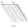
- the free face 9 of the diffusing plate 1 is then advantageously configured to in order to optimize the heat transmission surface, for example with a profile with a series of fins, as illustrated in Figure 3.
- the assembly electric heater is configured to form the body of an iron soleplate to redo.
- the conductive material for example a aluminum alloy
- the conductive material for example a aluminum alloy
- Plate 20 arranged against the free face 12 of the diffusing plate and struck simultaneously with the other elements of the whole serves as a sole.
- the ends 7 (fig. 1) of the heating element can be folded in a direction opposite to plate 1 and thus move away from the assembly.
- the tips thus arranged can be used for a standard type connection.
- the tips 7 can also extend in the plane of the assembly for exit by the side of it.
- the hitting dies are then provided with clearances to avoid any damage that could be caused to said tips.
- sensors in particular temperature sensors, enabling regulation and / or the safety of the heating assembly.
- sensors of known type, can be inserted between plates 1 and 2, for example near the heating element.
- Figure 2 illustrates the process used to assemble the different elements constituents of the electric heating assembly according to the invention.
- an assembly consisting of a plate 1 is used and at least a heating element 4, the plate whether or not comprising one or more grooves 3 preformed.
- the hot stamping is then carried out.
- This hot stamping is advantageously carried out at a temperature allowing optimal creep of the material constituting the diffusing plate 1.
- this temperature is between 400 ° C and 500 ° C and preferably around 455 ° C.
- the assembly of the different elements by hot stamping allows the whole is maintained by an intimate mechanical connection between the diffusing plate 1 and the adjoining portion of the heating elements 4.
- Figure 1 illustrates the result obtained with an element heater of substantially triangular section. In this case, the material of the plate 1, after creep, partially surrounds the edges of the heating element.
- Figure 4 illustrates the result obtained with a heating element of substantially circular section arranged against a plate forming a sole of iron.
- Hot stamping therefore has a multiple effect: strong cohesion between the heating element 4 and the adjacent portion of the diffusing plate 1, in particular the portion of the groove 3 filled by creep of the material of the diffusing plate.
- the resulting electric heating assembly therefore has a very large cohesion. It is also strong, stable and durable.
- the simplicity and the speed of the hot stamping process allows a wide range to be obtained of different embodiments, at a very advantageous cost.
- the process of hot typing also lends itself well to automation.
- a second advantageous embodiment of the invention is illustrated in Figures 1 'to 5'.
- the elements corresponding to those of Figures 1 to 5 have the same reference numbers.
- a cover plate 2 is arranged against the first plate, so as to cover the heating element. It is a plate made of a harder alloy than that of the plate diffusing 1, so as to promote the creep of the plate 1 during assembly, as described below. So we use a metal plate 2 advantageously made of steel.
- the cover plate advantageously occupies the entire covered area by the diffusing plate. It can extend more or less over the sides, as shown in Figure 1 ', so as to allow the formation of an edge 11 by example. It can also cover a smaller area and / or present openings or clearances where the plate 1 is free. We obtain then only a partial covering of the plate 1. According to various modes of realization, it is also possible to provide several plates of cover 2 arranged on the side of the heating element and / or even against the free face 9 of the diffusing plate 1 as described later in the example of an iron soleplate.
- one or more grooves 3 are then preformed in the or the plates in question, so as to form a housing in which rests at least a portion of the radial section of the corresponding heating element.
- the path of the groove is advantageously similar to that of the element corresponding heater. If you use a rather rigid cover plate and thick, the preformed grooves have the advantage of protecting the heating element placed in this groove during striking.
- the striking dies 10 are advantageously shaped as a function of the desired final contour of the cover plate and of the whole assembly. It is therefore advantageous to preform the grooves 3 'in the image of the desired final contour.
- the heating element benefits from a protection minimizing the deformations it could undergo during typing, since the plate of covering is for all practical purposes not distorted during typing.
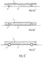
- non-preformed plates are used. It is then advantageous to use a thinner and / or more cover plate flexible, so as to allow this plate to follow the contour of the element heating and / or the one provided on the impact die, avoiding deterioration the heating element when typing. So, especially in the case of the figure 5a ', where no groove is preformed in the plates of the assembly, the strike 10 is advantageously shaped with a groove 3 'whose shape advantageously corresponds to the profile of the heating element.
- the groove is provided in the diffusing plate.
- the grooves 3 or 3 ' are shaped and arranged so as to minimize the deformations undergone by the casing 5 of the heating element 4 so that these deformations remain within acceptable limits, in particular for the purpose avoid any short circuit between the casing 5 and the core 6 of the heating element 4.
- the material of the diffusing plate fills the portion of the groove initially left free by the heating element, so as to surround at at least partially this one.
- the diffusing plate 1 plays in particular a role of conduction and distribution of thermal energy. In this way, thanks to a larger surface of transmission, avoiding unfavorable local overheating zones. For this reason, it is advantageous to use a material having good thermal conductivity characteristics. Given the holding effect provided by the addition of at least one attached plate, it is possible to make a heating assembly comprising several diffusing plates 1 juxtaposed to each other. The plates are then preferably placed close immediately relative to each other, or so as to be in contact with each other with the other.
- the electric heating assembly is configured so as to form the body of an iron soleplate.
- the material conductor for example an aluminum alloy, is advantageously arranged between two cover plates 2 and 20, for example made of stainless steel.
- the plate 2 plays a role similar to that described above.
- a sole plate of a known type whose sliding properties and wear resistance are advantageous. It is also possible to fix the plate 20 after striking, for example by gluing, riveting or screwing.
- the ends 7 of the heating element can be folded in a direction opposite plate 1 and exit from the assembly through holes or grooves specially provided for this purpose in the cover plate.
- the tips thus arranged can be used for a standard type connection.
- the tips 7 can also extend in the plane of the assembly for exit by the side of it.
- the hitting dies are provided with clearances to avoid any damage that could be caused to said tips.
- sensors in particular temperature sensors, enabling regulation and / or the safety of the heating assembly.
- sensors of known type, can be inserted between plates 1 and 2, for example near the element heating.
- Figure 2 Illustrates the process used for assembling the different elements constituents of the electric heating assembly according to the invention.
- a set of plates 1 and 2 is used and at least one heating element 4, the plates optionally comprising one or more grooves 3 preformed.
- the hot stamping is then carried out.
- This hot stamping is advantageously carried out at a temperature allowing optimal creep of the material constituting the diffusing plate 1.
- this temperature is between 400 ° C and 500 ° C and preferably around 455 ° C.
- the minimum pressure exerted during striking is advantageously around 250 N / mm 2 and the striking speed is generally at least 0.30 m / s.
- the assembly of the different elements by hot stamping allows the whole either maintained by an intimate mechanical connection between on the one hand the plate diffusing 1 and the cover plate 2 and on the other hand between the portion adjacent to the plate 1 and the heating element (s) 4.
- Hot stamping therefore has a multiple effect: on the one hand, strong cohesion between the diffusing plates 1 and the covering plates 2 and / or 20 reported; on the other hand, strong cohesion between the heating element 4 and the adjacent portion of the diffusing plate 1, in particular the portion of the groove 3 filled by creep of the material of the diffusing plate.
- This cohesive force also provides an additional clamping effect on the element heater 4 fixedly held between the portion of the cover plate 2 partially surrounding it and the adjacent portion of the diffusing plate 1.
- the resulting electric heating assembly therefore has a very large cohesion. It is also strong, stable and durable.
- the simplicity and the speed of the hot stamping process allows a wide range to be obtained of different embodiments, at a very advantageous cost.
- the process of hot typing also lends itself well to automation.
- the assembly process and the electric heating assembly according to the invention therefore make it possible to obtain, for example, a heating base or a thermal diffuser which can be regulated according to several heating stages, offering high thermal efficiency and optimal heat distribution and able to support significant powers without decohesion of the assembly long-term.
- the shapes and dimensions of the heating assembly may vary depending on of the whole range of corresponding applications.
- the invention finds its application in the production of heating assemblies electric.
Description
La présente invention concerne le domaine des ensembles chauffants électriques en général et s'applique plus particulièrement aux ensembles chauffants électriques comprenant au moins une plaque diffusante et au moins un élément chauffant fixé contre ladite plaque. Selon une variante avantageuse de l'invention, une plaque de recouvrement est également prévue.The present invention relates to the field of heating assemblies electrical in general and applies more particularly to assemblies electric heaters comprising at least one diffusing plate and at least a heating element fixed against said plate. According to an advantageous variant of the invention, a cover plate is also provided.
Elle concerne par ailleurs le procédé d'assemblage d'un tel ensemble chauffant électrique.It also relates to the method of assembling such a heating assembly electric.
Des ensembles chauffants électriques avec plaques diffusantes sont déjà connus. L'un des inconvénients de ces ensembles réside dans la complexité du mode d'assemblage des différents éléments constituants. En effet, dans la plupart des cas, les éléments chauffants sont fixés à un autre élément tel un support, par exemple par soudure. La réalisation d'une telle soudure nécessite un outillage sophistiqué et implique un mode opératoire long et coûteux. Cette opération affecte grandement l'aspect esthétique des éléments joints, et, est la source de nombreux problèmes de qualité.Electric heating assemblies with diffusing plates are already known. One of the drawbacks of these sets lies in the complexity of the method of assembling the various constituent elements. Indeed, in the in most cases the heating elements are attached to another element such as a support, for example by welding. The realization of such a weld requires sophisticated tools and involves a long and costly procedure. This operation greatly affects the aesthetic appearance of the attached elements, and, is the source of many quality problems.
On connaít également des éléments chauffants qui sont fixés par sertissage, collage, ou au moyen de fixations rivetées, vissées, soudées, etc. Dans de tels cas, l'assemblage résultant présente souvent certaines faiblesses au niveau de la cohésion entre les éléments pouvant affecter considérablement la durabilité du produit. De plus, les nombreuses pièces nécessaires à l'assemblage compliquent souvent celui-ci et le rendent coûteux. There are also known heating elements which are fixed by crimping, bonding, or by means of riveted, screwed, welded fasteners, etc. In such In this case, the resulting assembly often has certain weaknesses in terms of the cohesion between the elements which can considerably affect the durability of the product. In addition, the many parts required for assembly Often complicate it and make it expensive.
Il est également connu, par le document US-2,851,572 un procédé
d'assemblage d'un ensemble chauffant selon le préambule de la revendication 1. Ce dernier est cependant réalisé par frittage. Cette technique de mise en oeuvre, où les matériaux,
initialement sous la forme de poudre compactée, subissent un cycle long de
transformation sous pression et température, est complexe et nécessite un
temps d'élaboration conséquent, induisant des coûts importants pour réaliser
cette fonction d'assemblage.It is also known from document US-2,851,572 a process
assembly of a heating assembly according to the preamble of
L'invention a précisément pour but de remédier aux inconvénients et/ou aux limitations précités, et propose un procédé permettant de réaliser un ensemble chauffant électrique comprenant au moins une plaque diffusante et au moins un élément chauffant fixé contre ladite plaque, ledit ensemble étant réalisé par frappe à chaud. L'invention propose également l'ensemble chauffant électrique assemblé par frappe à chaud résultant.The object of the invention is precisely to remedy the drawbacks and / or the aforementioned limitations, and proposes a method making it possible to produce an assembly electric heater comprising at least one diffusing plate and at least one heating element fixed against said plate, said assembly being produced by hot stamping. The invention also provides the electric heating assembly assembled by hot stamping resulting.
Selon les formes d'exécution de l'invention, on peut utiliser des plaques diffusantes dans lesquelles le profil de l'élément chauffant :
- n'est pas préformé
ou - est préformé dans au moins une portion de la plaque diffusante et/ou, selon une forme avantageuse de l'invention,
- est préformé dans au moins une portion de la plaque de recouvrement.
- is not preformed
or - is preformed in at least a portion of the diffusing plate and / or, according to an advantageous form of the invention,
- is preformed in at least a portion of the cover plate.
Dans ces deux derniers cas, on préforme alors une gorge dans la ou les plaques en question. Le cheminement de la gorge est avantageusement similaire à celui de l'élément chauffant correspondant. Sous l'effet de la frappe, le matériau de la plaque diffusante s'immisce au moins partiellement autour des éléments chauffants par fluage de ce matériau. Dans les cas particuliers où une gorge est préformée, le matériau de la plaque diffusante remplit la portion de la gorge laissée initialement libre par l'élément chauffant, de façon à entourer au moins partiellement celui-ci. On obtient de la sorte une fixation résistante et durable. In the latter two cases, a groove is then preformed in the plate or plates in question. The path of the throat is advantageously similar to that of the corresponding heating element. Under the effect of striking, the material of the diffusing plate interferes at least partially around the elements heating by creep of this material. In special cases where a throat is preformed, the material of the diffusing plate fills the portion of the groove initially left free by the heating element, so as to surround at least partially this one. In this way, a resistant and durable fixing is obtained.
Par ailleurs, tel que décrit ultérieurement, l'outil de frappe est avantageusement conformé en fonction du profil de l'élément chauffant, notamment dans le but de minimiser les contraintes subies par ce dernier lors de la frappe.Furthermore, as described later, the striking tool is advantageously shaped according to the profile of the heating element, in particular for the purpose of minimize the stresses suffered by the latter during typing.
Un autre but de l'invention est de proposer un ensemble chauffant électrique qui soit parfaitement étanche.Another object of the invention is to propose an electric heating assembly which is perfectly waterproof.
Afin d'atteindre ces buts, il est prévu un procédé d'assemblage d'un ensemble
chauffant électrique comportant les caractéristiques de la revendication 1.In order to achieve these goals, a method of assembling an assembly is provided.
electric heater comprising the features of
Il est également prévu un ensemble chauffant électrique assemblé suivant le procédé décrit ci-haut, comprenant au moins une plaque diffusante en matériau métallique, et au moins un élément chauffant disposé contre ladite plaque, caractérisé en ce que l'ensemble est maintenu par une liaison mécanique intime entre la plaque diffusante et le ou les éléments chauffants.An electric heating assembly is also provided, assembled according to the process described above, comprising at least one diffusing plate of material metallic, and at least one heating element placed against said plate, characterized in that the assembly is maintained by an intimate mechanical connection between the diffusing plate and the heating element (s).
Les applications de cet ensemble chauffant électrique sont innombrables. Par exemple, dans le domaine des appareils électroménagers, il peut être utilisé notamment avec les générateurs de vapeur (pour repassage, nettoyage, etc), les cafetières, bouilloires, les récipients de cuisson à vapeur (sous pression ou non) tels les autocuiseurs, ainsi que tous genres de récipients de cuisson chauffants tels poêles, casseroles, wok, les friteuses, les plaques de cuisson, les plans de cuisson de formes particulières tels les grille-viandes, gaufriers, crêpiers, les fours, les panneaux radiants pour chauffage électrique, les semelles de fer à repasser, et de manière générale, tout dispositif comprenant un élément chauffant serti ou surmoulé, etc.The applications of this electric heating assembly are innumerable. Through example, in the field of household appliances, it can be used in particular with steam generators (for ironing, cleaning, etc.), coffee makers, kettles, steaming vessels (pressure or no) such as pressure cookers, as well as all kinds of cooking vessels heaters such as frying pans, pots, wok, fryers, hotplates, hobs of particular shapes such as meat grills, waffle irons, crepe makers, ovens, radiant panels for electric heating, soles of iron, and in general, any device comprising a crimped or overmolded heating element, etc.
D'autres caractéristiques et avantages de l'invention apparaítront plus clairement à la lumière de la description et des dessins qui suivent, illustrant, à titre d'exemples non limitatifs, des modes de mise en oeuvre de l'invention. Ainsi, référence est faite aux figures 1 à 5, où:
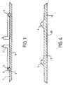
- la figure 1 représente une vue en coupe d'un exemple d'un ensemble chauffant électrique selon l'invention, après assemblage par frappe à chaud; la figure 1' représente le même exemple comprenant en plus une plaque de recouvrement.
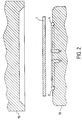
- la figure 2 représente un ensemble similaire ainsi que les matrices de la presse avant assemblage final par frappe à chaud; la figure 2' représente le même ensemble comprenant en plus une plaque de recouvrement.
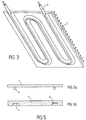
- la figure 3 illustre un panneau radiant réalisé à l'aide d'un ensemble chauffant électrique selon l'invention dont l'élément chauffant est en forme de serpentin; la figure 3' représente le même panneau comprenant en plus une plaque de recouvrement.
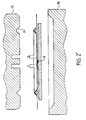
- la figure 4 illustre une semelle de fer à repasser réalisée à l'aide d'un ensemble chauffant électrique selon l'invention; la figure 4' illustre la même semelle, comprenant en plus une plaque de recouvrement.
- les figures 5a et 5b illustrent un ensemble chauffant électrique selon l'invention
avant assemblage par frappe à chaud, où au moins une gorge dont la forme
correspond avantageusement au profil de l'élément chauffant:
- à la figure 5a, n'est pas préformée dans la plaque diffusante;
- à la figure 5b, est préformée dans au moins une portion de la plaque diffusante.
- les figures 5a', 5b', 5c' illustrent un ensemble chauffant électrique selon
l'invention, avec plaque de recouvrement, avant assemblage par frappe à
chaud, où au moins une gorge dont la forme correspond avantageusement au
profil de l'élément chauffant :
- à la figure 5a', n'est pas préformée dans les plaques de l'ensemble;
- à la figure 5b', est préformée dans au moins une portion de la plaque diffusante;
- à la figure 5c', est préformée dans au moins une portion de la plaque de recouvrement.
- Figure 1 shows a sectional view of an example of an electric heating assembly according to the invention, after assembly by hot stamping; Figure 1 'shows the same example further comprising a cover plate.
- FIG. 2 represents a similar assembly as well as the dies of the press before final assembly by hot stamping; Figure 2 'shows the same assembly further comprising a cover plate.
- FIG. 3 illustrates a radiant panel produced using an electric heating assembly according to the invention, the heating element of which is in the form of a coil; Figure 3 'shows the same panel further comprising a cover plate.
- FIG. 4 illustrates an iron soleplate produced using an electric heating assembly according to the invention; Figure 4 'illustrates the same sole, further comprising a cover plate.
- FIGS. 5a and 5b illustrate an electric heating assembly according to the invention before assembly by hot striking, where at least one groove whose shape advantageously corresponds to the profile of the heating element:
- in Figure 5a, is not preformed in the diffusing plate;
- in Figure 5b, is preformed in at least a portion of the diffusing plate.
- FIGS. 5a ', 5b', 5c 'illustrate an electric heating assembly according to the invention, with cover plate, before assembly by hot stamping, where at least one groove whose shape advantageously corresponds to the profile of the heating element:
- in Figure 5a ', is not preformed in the plates of the assembly;
- in Figure 5b ', is preformed in at least a portion of the diffusing plate;
- in Figure 5c ', is preformed in at least a portion of the cover plate.
En faisant référence à la figure 1, l'ensemble chauffant électrique selon
l'invention comprend une plaque diffusante 1, réalisée de préférence à l'aide d'un
matériau métallique possédant une bonne malléabilité lorsqu'on le chauffe à
température modérée. Il peut s'agir par exemple d'une plaque en alliage
d'aluminium ou de cuivre dont la forme peut varier selon un très vaste éventail de
possibilités en fonction de l'utilisation prévue pour l'ensemble.Referring to Figure 1, the electric heater assembly according to
the invention comprises a diffusing
Un (ou plusieurs) élément chauffant 4 est disposé contre la plaque diffusante 1
(le singulier utilisé dans le reste de la présente demande pour des raisons de
simplification désigne en fait l'une ou l'autre possibilité). Il s'agit de préférence
d'un élément chauffant blindé de type connu. La section radiale de l'élément
chauffant peut être sensiblement circulaire, triangulaire ou autre. Le
cheminement suivi par l'élément chauffant dans le plan varie selon les modes
d'exécution. Il peut s'agir d'un cheminement circulaire, d'un cheminement en
forme de serpentin, de forme ovale ou quelconque. Il est également possible de
prévoir plusieurs éléments chauffants, disposés par exemple côte à côte ou
encore en cercles concentriques.One (or more)
Selon une forme d'exécution avantageuse de l'invention, on utilise des plaques non préformées. La frappe a alors pour effet de provoquer un mouvement partiel de la matière autour de l'élément chauffant et/ou de faire pénétrer au moins partiellement l'élément chauffant dans la plaque diffusante. According to an advantageous embodiment of the invention, plates are used not preformed. The strike then has the effect of causing a partial movement material around the heating element and / or to penetrate at least partially the heating element in the diffusing plate.
Selon une forme d'exécution avantageuse de l'invention, on peut utiliser des plaques diffusantes dans lesquelles au moins une gorge dont la forme correspond avantageusement au profil de l'élément chauffant:
- n'est pas préformée, tel qu'illustré à la figure 5a;
ou - est préformée dans au moins une portion de la plaque diffusante tel qu'illustré à la figure 5b;
- is not preformed, as shown in Figure 5a;
or - is preformed in at least a portion of the diffusing plate as illustrated in FIG. 5b;
Dans ce dernier cas, on préforme alors une ou plusieurs gorges 3 dans la ou les
plaques en question, de façon à former un logement dans lequel repose au
moins une portion de la section radiale de l'élément chauffant correspondant. Le
cheminement de la gorge est avantageusement similaire à celui de l'élément
chauffant correspondant.In the latter case, one or
Les matrices de frappe 10 sont avantageusement conformées en fonction du contour final souhaité de l'ensemble. Il est donc avantageux de préformer les gorges dans la plaque diffusante en fonction du contour final souhaité. Sous l'effet de la frappe, le matériau de la plaque diffusante remplit la portion de la gorge laissée initialement libre par l'élément chauffant, de façon à entourer au moins partiellement celui-ci.The striking dies 10 are advantageously shaped as a function of the desired final outline of the whole. It is therefore advantageous to preform the grooves in the diffusing plate according to the desired final contour. Under the effect of striking, the material of the diffusing plate fills the portion of the groove initially left free by the heating element, so as to surround at at least partially this one.
Ainsi, en particulier dans le cas de la figure 5a, où aucune gorge n'est préformée dans les plaques de l'ensemble, l'outil de frappe est avantageusement conformé avec une gorge dont la forme correspond avantageusement au profil de l'élément chauffant.Thus, in particular in the case of FIG. 5a, where no groove is preformed in the plates of the assembly, the striking tool is advantageously shaped with a groove whose shape advantageously corresponds to the profile of the element heating.
On peut évidemment combiner les diverses variantes afin de préformer les gorges à l'endroit le plus convenable, selon l'utilisation prévue de l'ensemble chauffant électrique résultant.We can obviously combine the various variants in order to preform the grooves in the most suitable place, according to the intended use of the set resulting electric heater.
Les gorges 3 ou 3' sont conformées et disposées de façon à minimiser les
déformations subies par l'enveloppe 5 (fig. 1 et 1') de l'élément chauffant 4 afin
que ces déformations demeurent dans des limites acceptables, notamment dans
le but d'éviter tout court-circuit entre l'enveloppe 5 et l'âme 6 de l'élément
chauffant 4.The
La plaque diffusante 1 joue notamment un rôle de conduction et répartition de
l'énergie thermique. De cette façon, grâce à une plus grande surface de
transmission, on évite les zones de surchauffe locale défavorables. Pour cette
raison, on utilise avantageusement un matériau présentant de bonnes
caractéristiques de conductibilité thermique.The diffusing
Selon l'utilisation prévue de l'ensemble thermique chauffant, la plaque diffusante peut remplir une multiplicité d'autres fonctions. Ainsi, il peut s'agir d'une plaque sensiblement plane servant par exemple de support sur lequel on dépose un objet destiné à être chauffé, comme par exemple un récipient de cuisson. Il peut également s'agir du fond d'un récipient. Dans ce cas, le contour de la plaque peut être conformé de façon à servir de parois pour le récipient.Depending on the intended use of the heating thermal assembly, the diffusing plate can fulfill a multiplicity of other functions. So it can be a plate substantially flat serving for example as a support on which a object intended to be heated, such as for example a cooking vessel. he can also be the bottom of a container. In this case, the outline of the plate can be shaped to serve as walls for the container.
Autrement, plutôt que de servir directement de fond d'un récipient comme dans le cas précédent, la plaque peut également être juxtaposée à un autre élément, servant lui-même de fond d'un récipient. Cette variante permet d'adapter avec une grande aisance l'ensemble chauffant selon l'invention à une multiplicité d'éléments, notamment dans le but d'obtenir des caractéristiques de chauffe optimales.Otherwise, rather than serving directly as the bottom of a container as in the previous case, the plate can also be juxtaposed to another element, itself serving as the bottom of a container. This variant allows to adapt with a great ease the heating assembly according to the invention to a multiplicity elements, in particular in order to obtain heating characteristics optimal.
Dans tous ces exemples, la plaque diffusante permet en particulier de
transmettre l'énergie thermique générée par l'élément chauffant depuis celui-ci
vers la surface libre 9 de la plaque diffusante 1.In all of these examples, the diffusing plate makes it possible in particular to
transmit the thermal energy generated by the heating element from it
towards the
L'ensemble chauffant électrique peut également être configuré en fonction
d'autres types d'applications, pour servir par exemple de panneau chauffant.
Dans un tel cas, il est avantageux d'isoler la face externe de la plaque 2 et de
prévoir un moyen de support permettant de disposer verticalement l'ensemble. The electric heating unit can also be configured according to
other types of applications, to serve for example as a heating panel.
In such a case, it is advantageous to isolate the external face of the
La face libre 9 de la plaque diffusante 1 est alors avantageusement configurée de
façon à optimiser la surface de transmission de chaleur, par exemple avec un
profil présentant une série d'ailettes, comme illustré à la figure 3.The
Une fois la frappe effectuée, on souhaitera souvent protéger et/ou isoler la face libre de l'élément chauffant, notamment pour des raisons de sécurité. Il est alors avantageux de disposer un élément rapporté de façon à recouvrir cette face libre.Once the strike is made, we will often want to protect and / or isolate the face free of the heating element, in particular for safety reasons. So he is advantageous to have an added element so as to cover this free face.
Par ailleurs, selon une autre forme d'exécution illustrée à la figure 4, l'ensemble
chauffant électrique est configuré de façon à former le corps d'une semelle de fer
à repasser. Selon ce mode d'exécution, le matériau conducteur, par exemple un
alliage d'aluminium, est avantageusement disposé contre une plaque rapportée
20 par exemple en acier inoxydable. La plaque 20, disposée contre la face libre
12 de la plaque diffusante et frappée simultanément avec les autres éléments de
l'ensemble, sert de semelle. Pour cette raison, on utilise de préférence une
plaque de semelle de type connu dont les propriétés de glisse et de résistance à
l'usure sont avantageuses. Il est également possible de fixer la plaque 20 après
la frappe, par exemple par collage, rivetage ou vissage.Furthermore, according to another embodiment illustrated in Figure 4, the assembly
electric heater is configured to form the body of an iron soleplate
to redo. According to this embodiment, the conductive material, for example a
aluminum alloy, is advantageously placed against an attached
Les embouts 7 (fig. 1) de l'élément chauffant peuvent être repliés suivant une
direction opposée à la plaque 1 et ainsi s'éloigner de l'ensemble. Les embouts
ainsi disposés peuvent être utilisés pour un branchement de type standard. Les
embouts 7 peuvent également se prolonger dans le plan de l'ensemble pour
sortir par le côté de celui-ci. Les matrices de frappe sont alors prévues avec des
dégagements pour éviter tout dommage qui pourrait être causé auxdits embouts.The ends 7 (fig. 1) of the heating element can be folded in a
direction opposite to
Par ailleurs, selon diverses variantes, il est prévu d'insérer des capteurs,
notamment des capteurs de température, permettant d'assurer la régulation et/ou
la sécurité de l'ensemble chauffant. Ces capteurs, de type connu, peuvent être
insérés entre les plaques 1 et 2, par exemple à proximité de l'élément chauffant. Furthermore, according to various variants, it is planned to insert sensors,
in particular temperature sensors, enabling regulation and / or
the safety of the heating assembly. These sensors, of known type, can be
inserted between
La figure 2 illustre le procédé utilisé pour l'assemblage des différents éléments constituants de l'ensemble chauffant électrique selon l'invention.Figure 2 illustrates the process used to assemble the different elements constituents of the electric heating assembly according to the invention.
Tel que déjà décrit, on utilise un ensemble constitué d'une plaque 1 et au moins
un élément chauffant 4, la plaque comprenant ou non une ou plusieurs gorges 3
préformées.As already described, an assembly consisting of a
Selon une variante d'exécution avantageuse, il est prévu de prépositionner ou de préassembler les éléments chauffants contre la plaque par tout moyen approprié de type connu, comme par exemple par soudage 8 (fig. 2'), par collage, sertissage, etc, afin de faciliter la réalisation de la frappe.According to an advantageous alternative embodiment, provision is made for prepositioning or pre-assemble the heating elements against the plate by any suitable means of known type, such as by welding 8 (fig. 2 '), by gluing, crimping, etc., to facilitate the striking process.
Il peut s'avérer avantageux d'utiliser un lubrifiant approprié de type connu afin d'éviter tout problème d'adhérence de l'un ou l'autre des éléments de l'ensemble contre les outils de frappe.It may be advantageous to use an appropriate lubricant of known type in order to to avoid any problem of adhesion of one or other of the elements of the assembly against striking tools.
On effectue ensuite la frappe à chaud.The hot stamping is then carried out.
Cette frappe à chaud est avantageusement réalisée à une température
permettant un fluage optimal du matériau constituant la plaque diffusante 1. Pour
l'aluminium et ses alliages, cette température se situe entre 400°C et 500°C et de
préférence autour de 455° C.This hot stamping is advantageously carried out at a temperature
allowing optimal creep of the material constituting the diffusing
L'assemblage des différents éléments par frappe à chaud permet que l'ensemble
soit maintenu par une liaison mécanique intime entre la plaque diffusante 1 et la
portion attenante des éléments chauffants 4.The assembly of the different elements by hot stamping allows the whole
is maintained by an intimate mechanical connection between the diffusing
Tel qu'illustré à la figure 1, sous l'effet de la frappe, le matériau de la plaque
diffusante s'immisce au moins partiellement autour de l'élément chauffant par
fluage de ce matériau. La figure 1 illustre le résultat obtenu avec un élément
chauffant de section sensiblement triangulaire. Dans ce cas, le matériau de la
plaque 1, après fluage, entoure partiellement les rebords de l'élément chauffant. As illustrated in Figure 1, under the effect of striking, the material of the plate
diffusing at least partially interferes around the heating element by
creep of this material. Figure 1 illustrates the result obtained with an element
heater of substantially triangular section. In this case, the material of the
La figure 4 illustre quant à elle le résultat obtenu avec un élément chauffant de section sensiblement circulaire agencé contre une plaque formant une semelle de fer à repasser.Figure 4 illustrates the result obtained with a heating element of substantially circular section arranged against a plate forming a sole of iron.
La frappe à chaud procure donc un effet multiple: une forte cohésion entre
l'élément chauffant 4 et la portion adjacente de la plaque diffusante 1, notamment
la portion de la gorge 3 remplie par fluage du matériau de la plaque diffusante.
L'ensemble chauffant électrique résultant présente donc une très grande
cohésion. Il est également résistant, stable et durable. Par ailleurs, la simplicité et
la rapidité du procédé de frappe à chaud permettent d'obtenir une vaste gamme
de formes d'exécution différentes, à un coût très avantageux. Le procédé de
frappe à chaud se prête par ailleurs bien à l'automatisation.Hot stamping therefore has a multiple effect: strong cohesion between
the
Un deuxième mode de réalisation avantageux de l'invention, est illustré aux
figures 1' à 5'. Dans ces figures, les éléments correspondant à ceux des figures 1
à 5 portent les mêmes références numériques. Une plaque de recouvrement 2
est disposée contre la première plaque, de façon à recouvrir l'élément chauffant.
Il s'agit d'une plaque réalisée en un alliage plus dur que celui de la plaque
diffusante 1, de façon à favoriser le fluage de la plaque 1 lors de l'assemblage,
tel que décrit ci-après. Ainsi, on utilise une plaque 2 métallique
avantageusement en acier.A second advantageous embodiment of the invention is illustrated in
Figures 1 'to 5'. In these figures, the elements corresponding to those of Figures 1
to 5 have the same reference numbers. A
La plaque de recouvrement occupe avantageusement toute la surface couverte
par la plaque diffusante. Elle peut déborder plus ou moins sur les côtés, comme
le montre la figure 1', de façon à permettre la formation d'un bord 11 par
exemple. Elle peut également couvrir une surface moins importante et/ou
présenter des ouvertures ou dégagements où la plaque 1 est libre. On obtient
alors un recouvrement uniquement partiel de la plaque 1. Selon divers modes de
réalisation, il est également possible de prévoir plusieurs plaques de
recouvrement 2 disposées du côté de l'élément chauffant et/ou même contre la
face libre 9 de la plaque diffusante 1 tel que cela est décrit ultérieurement dans
l'exemple d'une semelle de fer à repasser. The cover plate advantageously occupies the entire covered area
by the diffusing plate. It can extend more or less over the sides, as
shown in Figure 1 ', so as to allow the formation of an edge 11 by
example. It can also cover a smaller area and / or
present openings or clearances where the
Selon les multiples variantes de ce deuxième mode de réalisation de l'invention, on peut utiliser des plaques diffusantes et de recouvrement dans lesquelles au moins une gorge dont la forme correspond avantageusement au profil de l'élément chauffant:
- n'est pas préformée, tel qu'illustré à la figure 5a';
- est préformée dans au moins une portion de la plaque diffusante tel qu'illustré
à la figure 5b';
et/ou - est préformée dans au moins une portion de la plaque de recouvrement, tel qu'illustré à la figure 5c';
- is not preformed, as illustrated in Figure 5a ';
- is preformed in at least a portion of the diffusing plate as illustrated in FIG. 5b ';
and or - is preformed in at least a portion of the cover plate, as illustrated in FIG. 5c ';
Dans les deux derniers cas, on préforme alors une ou plusieurs gorges 3 dans la
ou les plaques en question, de façon à former un logement dans lequel repose
au moins une portion de la section radiale de l'élément chauffant correspondant.
Le cheminement de la gorge est avantageusement similaire à celui de l'élément
chauffant correspondant. Si on utilise une plaque de recouvrement plutôt rigide et
d'épaisseur importante, les gorges préformées présentent l'avantage de protéger
l'élément chauffant disposé dans cette gorge lors de la frappe.In the latter two cases, one or
Les matrices de frappe 10 sont avantageusement conformées en fonction du contour final souhaité de la plaque de recouvrement et de tout l'ensemble. Il est donc avantageux de préformer les gorges 3' à l'image du contour final souhaité. Dans ce cas, l'élément chauffant bénéficie d'une protection minimisant les déformations qu'il pourrait subir lors de la frappe, puisque la plaque de recouvrement n'est à toutes fins pratiques pas déformée lors de la frappe.The striking dies 10 are advantageously shaped as a function of the desired final contour of the cover plate and of the whole assembly. It is therefore advantageous to preform the grooves 3 'in the image of the desired final contour. In this case, the heating element benefits from a protection minimizing the deformations it could undergo during typing, since the plate of covering is for all practical purposes not distorted during typing.
Selon une variante du procédé, on utilise des plaques non préformées. Il est
alors avantageux d'utiliser une plaque de recouvrement plus mince et/ou plus
souple, de façon à permettre à cette plaque d'épouser le contour de l'élément
chauffant et/ou celui prévu sur la matrice de frappe en évitant de détériorer
l'élément chauffant lors de la frappe. Ainsi, en particulier dans le cas de la figure
5a', où aucune gorge n'est préformée dans les plaques de l'ensemble, l'outil de
frappe 10 est avantageusement conformé avec une gorge 3' dont la forme
correspond avantageusement au profil de l'élément chauffant.According to a variant of the method, non-preformed plates are used. It is
then advantageous to use a thinner and / or more cover plate
flexible, so as to allow this plate to follow the contour of the element
heating and / or the one provided on the impact die, avoiding deterioration
the heating element when typing. So, especially in the case of the figure
5a ', where no groove is preformed in the plates of the assembly, the
Selon une autre variante, la gorge est prévue dans la plaque diffusante.According to another variant, the groove is provided in the diffusing plate.
On peut évidemment combiner ces diverses variantes afin de préformer les gorges à l'endroit le plus convenable, selon l'utilisation prévue de l'ensemble chauffant électrique résultant.We can obviously combine these various variants in order to preform the grooves in the most suitable place, according to the intended use of the set resulting electric heater.
Les gorges 3 ou 3' sont conformées et disposées de façon à minimiser les
déformations subies par l'enveloppe 5 de l'élément chauffant 4 afin que ces
déformations demeurent dans des limites acceptables, notamment dans le but
d'éviter tout court-circuit entre l'enveloppe 5 et l'âme 6 de l'élément chauffant 4.The
Sous l'effet de la frappe, le matériau de la plaque diffusante remplit la portion de la gorge laissée initialement libre par l'élément chauffant, de façon à entourer au moins partiellement celui-ci.Under the effect of striking, the material of the diffusing plate fills the portion of the groove initially left free by the heating element, so as to surround at at least partially this one.
La plaque diffusante 1 joue notamment un rôle de conduction et répartition de
l'énergie thermique. De cette façon, grâce à une plus grande surface de
transmission, on évite les zones de surchauffe locale défavorables. Pour cette
raison, on utilise avantageusement un matériau présentant de bonnes
caractéristiques de conductibilité thermique. Etant donné l'effet de maintien
procuré par l'ajout d'au moins une plaque rapportée, il est possible de réaliser un
ensemble de chauffage comportant plusieurs plaques diffusantes 1 juxtaposées
l'une à l'autre. Les plaques sont alors préférablement disposées à proximité
immédiate l'une par rapport à l'autre, ou encore de façon à être en contact l'une
avec l'autre. The diffusing
Par ailleurs, selon une autre variante de ce second mode de réalisation illustrée à
la figure 4', l'ensemble chauffant électrique est configuré de façon à former le
corps d'une semelle de fer à repasser. Selon ce mode d'exécution, le matériau
conducteur, par exemple un alliage d'aluminium, est avantageusement disposé
entre deux plaques de recouvrement 2 et 20 par exemple en acier inoxydable. La
plaque 2 joue un rôle similaire à celui décrit plus haut. La plaque 20, disposée
contre la face libre 12 de la plaque diffusante et frappée simultanément avec les
autres éléments de l'ensemble, sert de semelle. Pour cette raison, on utilise de
préférence une plaque de semelle de type connu dont les propriétés de glisse et
de résistance à l'usure sont avantageuses. Il est également possible de fixer la
plaque 20 après la frappe, par exemple par collage, rivetage ou vissage.Furthermore, according to another variant of this second embodiment illustrated in
FIG. 4 ′, the electric heating assembly is configured so as to form the
body of an iron soleplate. According to this embodiment, the material
conductor, for example an aluminum alloy, is advantageously arranged
between two
Les embouts 7 de l'élément chauffant peuvent être repliés suivant une direction
opposée à la plaque 1 et sortir hors de l'ensemble par des orifices ou rainures
spécialement prévus à cette fin dans la plaque de recouvrement. Les embouts
ainsi disposés peuvent être utilisés pour un branchement de type standard. Les
embouts 7 peuvent également se prolonger dans le plan de l'ensemble pour
sortir par le côté de celui-ci. Les matrices de frappe sont prévues avec des
dégagements pour éviter tout dommage qui pourrait être causé auxdits embouts.The ends 7 of the heating element can be folded in a direction
opposite
Par ailleurs, selon diverses variantes, il est prévu d'insérer des capteurs,
notamment des capteurs de température, permettant d'assurer la régulation
et/ou la sécurité de l'ensemble chauffant. Ces capteurs, de type connu, peuvent
être insérés entre les plaques 1 et 2, par exemple à proximité de l'élément
chauffant.Furthermore, according to various variants, it is planned to insert sensors,
in particular temperature sensors, enabling regulation
and / or the safety of the heating assembly. These sensors, of known type, can
be inserted between
La figure 2' illustre le procédé utilisé pour l'assemblage des différents éléments constituants de l'ensemble chauffant électrique selon l'invention.Figure 2 'illustrates the process used for assembling the different elements constituents of the electric heating assembly according to the invention.
Tel que déjà décrit, on utilise un ensemble de plaques 1 et 2 et au moins un
élément chauffant 4, les plaques comprenant ou non une ou plusieurs gorges 3
préformées. As already described, a set of
Selon une variante d'exécution avantageuse, il est prévu de prépositionner ou de préassembler les plaques par tout moyen approprié de type connu, comme par exemple par soudage 8, par collage, sertissage, etc., afin de faciliter la réalisation de la frappe.According to an advantageous alternative embodiment, provision is made for prepositioning or pre-assemble the plates by any suitable means of known type, such as example by welding 8, by bonding, crimping, etc., in order to facilitate the realization of the strike.
Il peut s'avérer avantageux d'utiliser un lubrifiant approprié de type connu afin
d'éviter tout problème d'adhérence de l'un ou l'autre des éléments de l'ensemble
contre les outils de frappe 10.It may be advantageous to use an appropriate lubricant of known type in order to
to avoid any problem of adhesion of one or other of the elements of the assembly
against
On effectue ensuite la frappe à chaud.The hot stamping is then carried out.
Cette frappe à chaud est avantageusement réalisée à une température
permettant un fluage optimal du matériau constituant la plaque diffusante 1. Pour
l'aluminium et ses alliages, cette température se situe entre 400°C et 500°C et de
préférence autour de 455° C.This hot stamping is advantageously carried out at a temperature
allowing optimal creep of the material constituting the diffusing
Dans le cas où la plaque diffusante est en aluminium, la pression minimale exercée lors de la frappe se situe avantageusement autour de 250 N/mm2 et la vitesse de frappe est en général d'au moins 0.30 m/s.In the case where the diffusing plate is made of aluminum, the minimum pressure exerted during striking is advantageously around 250 N / mm 2 and the striking speed is generally at least 0.30 m / s.
L'assemblage des différents éléments par frappe à chaud permet que l'ensemble
soit maintenu par une liaison mécanique intime entre d'une part la plaque
diffusante 1 et la plaque de recouvrement 2 et d'autre part entre la portion
attenante de la plaque 1 et le ou les éléments chauffants 4.The assembly of the different elements by hot stamping allows the whole
either maintained by an intimate mechanical connection between on the one hand the plate
diffusing 1 and the
Dans le cas avantageux où une gorge est formée dans la plaque de recouvrement, celle-ci étant la plus rigide des deux plaques, on obtient des conditions permettant à la fois une protection de l'élément chauffant et un fluage facilité lors de la frappe à chaud de la plaque diffusante en matériau plus mou. Tel qu'illustré à la figure 1', sous l'effet de la frappe, le matériau de la plaque diffusante s'immisce au moins partiellement autour de l'élément chauffant par fluage de ce matériau. En effet, le matériau de la plaque diffusante remplit la portion de la gorge laissée libre par l'élément chauffant. La figure 1' illustre le résultat obtenu avec un élément chauffant de section sensiblement triangulaire. Dans ce cas, le matériau qui s'est immiscé partiellement dans la gorge entoure partiellement les rebords de l'élément chauffant. La figure 4' illustre quant à elle le résultat obtenu avec un élément chauffant de section sensiblement circulaire agencé entre un ensemble de plaques de façon à former une semelle de fer à repasser.In the advantageous case where a groove is formed in the plate overlap, the latter being the more rigid of the two plates, conditions allowing both protection of the heating element and creep ease when hot stamping the diffusing plate made of softer material. As illustrated in Figure 1 ', under the effect of striking, the material of the plate diffusing at least partially interferes around the heating element by creep of this material. Indeed, the material of the diffusing plate fills the portion of the throat left free by the heating element. Figure 1 'illustrates the result obtained with a heating element of substantially triangular section. In this case, the material that has partially interfered in the groove surrounds partially the edges of the heating element. Figure 4 'illustrates the result obtained with a heating element of substantially circular section arranged between a set of plates so as to form an iron sole iron.
La frappe à chaud procure donc un effet multiple: d'une part, une forte cohésion
entre les plaques diffusantes 1 et les plaques de recouvrement 2 et/ou 20
rapportées; d'autre part, une forte cohésion entre l'élément chauffant 4 et la
portion adjacente de la plaque diffusante 1, notamment la portion de la gorge 3
remplie par fluage du matériau de la plaque diffusante. Cette force de cohésion
procure également un effet additionnel de maintien par serrage de l'élément
chauffant 4 maintenu de façon fixe entre la portion de la plaque de recouvrement
2 l'entourant partiellement et la portion adjacente de la plaque diffusante 1.
L'ensemble chauffant électrique résultant présente donc une très grande
cohésion. Il est également résistant, stable et durable. Par ailleurs, la simplicité et
la rapidité du procédé de frappe à chaud permettent d'obtenir une vaste gamme
de formes d'exécution différentes, à un coût très avantageux. Le procédé de
frappe à chaud se prête par ailleurs bien à l'automatisation.Hot stamping therefore has a multiple effect: on the one hand, strong cohesion
between the diffusing
Il est à noter que contrairement à ce que l'on aurait pu prédire, la frappe à chaud n'endommage aucunement l'élément chauffant. En effet, les forces et les vitesses impliquées dans ce type de procédés sont telles que tout aurait porté à croire que l'élément chauffant n'en sortirait pas indemne.It should be noted that contrary to what one could have predicted, the hot typing does not damage the heating element. Indeed, the forces and speeds involved in this type of process are such that everything would have led to believe that the heating element would not come out unscathed.
Le procédé d'assemblage ainsi que l'ensemble chauffant électrique selon l'invention permettent donc d'obtenir par exemple un fond chauffant ou un diffuseur thermique pouvant être régulé suivant plusieurs allures de chauffe, offrant un rendement thermique élevé ainsi qu'une répartition calorifique optimale et pouvant supporter des puissances importantes sans décohésion de l'ensemble à long terme.The assembly process and the electric heating assembly according to the invention therefore make it possible to obtain, for example, a heating base or a thermal diffuser which can be regulated according to several heating stages, offering high thermal efficiency and optimal heat distribution and able to support significant powers without decohesion of the assembly long-term.
Les formes et les dimensions de l'ensemble chauffant peuvent varier en fonction de toute la panoplie d'application correspondante.The shapes and dimensions of the heating assembly may vary depending on of the whole range of corresponding applications.
L'invention n'est pas limitée aux exemples décrits et représentés. Diverses modifications peuvent y être apportées sans sortir du cadre de l'invention.The invention is not limited to the examples described and shown. Various modifications can be made without departing from the scope of the invention.
L'invention trouve son application dans la réalisation d'ensembles chauffants électriques.The invention finds its application in the production of heating assemblies electric.
Claims (17)
- A method of assembling an electric heater assembly comprising at least one diffusing plate (1) of metal material and at least one heater element (4) disposed against said diffusing plate(s) (1), the method being characterized in that it includes, after the heater elements have been placed against the diffusing plate(s) (1), hot-stamping the electric heater assembly, said hot-stamping being performed at a temperature, a pressure, and a speed of stamping that enable the material of the diffusing plate (1) to flow plastically, thereby providing cohesion between the heater elements and said diffusing plate (1).
- A method of assembling an electric heater assembly according to claim 1, in which said temperature for plastic flow lies in the range 400°C to 500°C, and preferably around 455°C.
- A method of assembling an electric heater assembly according to claim 1 or 2, in which the hot-stamping is performed with a minimum pressure situated around 250 N/mm2.
- A method of assembling an electric heater assembly according to any one of claims 1 to 3, in which the hot-stamping is performed at a minimum speed of 0.30 m/s.
- A method of assembling an electric heater assembly according to any one of claims 1 to 4, in which at least two of the component elements of the assembly are pre-positioned or pre-assembled, prior to hot-stamping, by welding (8), adhesive, or crimping.
- A method of assembling an electric heater assembly according to any one of claims 1 to 5, the method including the following preliminary steps:at lest one groove (3, 3') for associating with said at least one heater element (4) is pre-formed in at least a portion of said diffusing plate(s) (1) and/or in the stamping tool (10); andeach heater element (4) associated with a given groove (3, 3') is disposed against the corresponding diffusing plates (1) so as to follow a path substantially similar to that of the corresponding groove.
- A method of assembling an electric heater assembly according to any one of claims 1 to 5, said assembly further comprising at least one cover plate (2; 20), the method including the following steps:the heater elements (4) are disposed between the diffusing plates (1) and the cover plates (2); andthe assembly is subjected to hot-stamping.
- A method of assembling an electric heater assembly according to claim 7, including the following preliminary steps:at least one groove (3, 3') for associating with said at least one heater element (4) is pre-formed in at least a portion of said cover plate(s) (2) and/or in at least a portion of said diffusing plate(s) (1) and/or in the stamping tool (10); andeach heater element (4) associated with a given groove (3, 3') is disposed between the cover plates (2) and the corresponding diffusing plates (1) so as to follow a path substantially similar to that of the corresponding groove (3, 3').
- A method of assembling an electric heater assembly according to any one of claims 1, 2, 3, 4, 5, or 7, in which, under the effect of the stamping, the material of the diffusing plate (1) is moved at least in part around the heater elements (4) by said material being subject to plastic flow.
- A method of assembling an electric heater assembly according to claim 6 or 8, in which, under the effect of stamping, the material of the diffusing plate fills the portion of the groove (3, 3') left empty by the heater element (4) so as to surround it at least in part.
- A method of assembling an electric heater assembly according to claim 6 or 8, in which said grooves (3, 3') are shaped so as to present a shape corresponding substantially to the outline of the associated heater element (4).
- An electric heater assembly obtained by the method according to any one of claims 1 to 11.
- An electric domestic appliance including an electric heater assembly according to claim 12.
- An electric domestic appliance according to claim 13, constituting a cooking appliance.
- An electric domestic appliance according to claim 13, constituting a device for heating a fluid, in particular water.
- An electric domestic appliance according to claim 13, constituting a radiant heater panel.
- An electric domestic appliance according to claim 13, constituting a smoothing device, in particular a soleplate for a smoothing iron.
Applications Claiming Priority (5)
| Application Number | Priority Date | Filing Date | Title |
|---|---|---|---|
| FR9501348 | 1995-02-01 | ||
| FR9501347 | 1995-02-01 | ||
| FR9501347A FR2730119B1 (en) | 1995-02-01 | 1995-02-01 | ELECTRIC HEATING ASSEMBLY |
| FR9501348A FR2730120B1 (en) | 1995-02-01 | 1995-02-01 | HEATING ELEMENT WITH DIFFUSING PLATE |
| PCT/FR1996/000167 WO1996024233A1 (en) | 1995-02-01 | 1996-01-31 | Heating element with a diffusing plate, and method for assembling same |
Publications (2)
| Publication Number | Publication Date |
|---|---|
| EP0807367A1 EP0807367A1 (en) | 1997-11-19 |
| EP0807367B1 true EP0807367B1 (en) | 2000-04-26 |
Family
ID=26231740
Family Applications (1)
| Application Number | Title | Priority Date | Filing Date |
|---|---|---|---|
| EP96902320A Expired - Lifetime EP0807367B1 (en) | 1995-02-01 | 1996-01-31 | Heating element with a diffusing plate, and method for assembling same |
Country Status (10)
| Country | Link |
|---|---|
| EP (1) | EP0807367B1 (en) |
| JP (1) | JPH10513303A (en) |
| KR (1) | KR19980701703A (en) |
| CN (1) | CN1172574A (en) |
| AU (1) | AU4667696A (en) |
| BR (1) | BR9607163A (en) |
| DE (1) | DE69607939T2 (en) |
| ES (1) | ES2147916T3 (en) |
| GR (1) | GR3033778T3 (en) |
| WO (1) | WO1996024233A1 (en) |
Families Citing this family (7)
| Publication number | Priority date | Publication date | Assignee | Title |
|---|---|---|---|---|
| FR2762531B1 (en) * | 1997-04-28 | 1999-08-13 | Superba Sa | OMNIDIRECTIONAL PORTABLE VAPOR CLEANING DEVICE FOR HARD OR SOFT SURFACES |
| US7121024B1 (en) | 2005-10-17 | 2006-10-17 | Suzanne T Clevenberg | Creaser steam iron |
| EP2213784B1 (en) * | 2009-01-30 | 2015-03-11 | Polne, S.L. | Soleplate and iron comprising such a soleplate |
| CN104080213A (en) * | 2013-03-29 | 2014-10-01 | 宁波吉毅电器有限公司 | Aluminum plate type electric heater capable of radiating rapidly |
| CN104219801A (en) * | 2013-05-29 | 2014-12-17 | 宁波吉毅电器有限公司 | Novel rapid heat-dissipation electric heater |
| WO2015106054A1 (en) | 2014-01-09 | 2015-07-16 | Herrild Natalie | Ironing device |
| FR3033679A1 (en) | 2015-03-11 | 2016-09-16 | Fanien Hubert Jean Louis Henri Delelis | METHOD OF ASSEMBLING PLATE-TYPE HEATING ELEMENT AND HEATING ARTICLE THEREFOR |
Family Cites Families (7)
| Publication number | Priority date | Publication date | Assignee | Title |
|---|---|---|---|---|
| US2851572A (en) * | 1957-05-13 | 1958-09-09 | Raybestos Manhattan Inc | Heating unit |
| US3221396A (en) * | 1960-07-15 | 1965-12-07 | Gen Motors Corp | Method of forming a solid plate cooking unit |
| US3581144A (en) * | 1969-03-27 | 1971-05-25 | Gen Electric | Metal-clad insulated electrical heater |
| GB1395011A (en) * | 1973-08-24 | 1975-05-21 | Suhl Elektrogeraete Veb K | Fastening of tubes containing heating elements on a carrier plate |
| DE2461249A1 (en) * | 1974-12-23 | 1976-06-24 | Elpag Ag Chur | Joining metal parts of domestic ware etc by connecting elements - latter pressed into one component which undergoes plastic deformation and anchors element |
| US4045653A (en) * | 1976-06-28 | 1977-08-30 | National Presto Industries, Inc. | Electric cooker with press-staked heating element and method of making the same |
| GB1590836A (en) * | 1977-11-21 | 1981-06-10 | Ass Eng Ltd | Electrically heated apparatus |
-
1996
- 1996-01-31 EP EP96902320A patent/EP0807367B1/en not_active Expired - Lifetime
- 1996-01-31 WO PCT/FR1996/000167 patent/WO1996024233A1/en not_active Application Discontinuation
- 1996-01-31 CN CN96191728A patent/CN1172574A/en active Pending
- 1996-01-31 JP JP8523318A patent/JPH10513303A/en active Pending
- 1996-01-31 AU AU46676/96A patent/AU4667696A/en not_active Abandoned
- 1996-01-31 DE DE69607939T patent/DE69607939T2/en not_active Expired - Fee Related
- 1996-01-31 BR BR9607163A patent/BR9607163A/en not_active Application Discontinuation
- 1996-01-31 ES ES96902320T patent/ES2147916T3/en not_active Expired - Lifetime
- 1996-01-31 KR KR1019970705099A patent/KR19980701703A/en not_active Application Discontinuation
-
2000
- 2000-06-23 GR GR20000401475T patent/GR3033778T3/en not_active IP Right Cessation
Also Published As
| Publication number | Publication date |
|---|---|
| JPH10513303A (en) | 1998-12-15 |
| CN1172574A (en) | 1998-02-04 |
| ES2147916T3 (en) | 2000-10-01 |
| AU4667696A (en) | 1996-08-21 |
| EP0807367A1 (en) | 1997-11-19 |
| WO1996024233A1 (en) | 1996-08-08 |
| MX9705805A (en) | 1998-07-31 |
| DE69607939T2 (en) | 2000-11-09 |
| KR19980701703A (en) | 1998-06-25 |
| DE69607939D1 (en) | 2000-05-31 |
| BR9607163A (en) | 1997-11-11 |
| GR3033778T3 (en) | 2000-10-31 |
Similar Documents
| Publication | Publication Date | Title |
|---|---|---|
| FR2718936A1 (en) | Kitchen utensil with multiple bottom structure and method of making said kitchen utensil. | |
| FR2711051A1 (en) | Cooking container with controlled bottom deformation. | |
| EP0807367B1 (en) | Heating element with a diffusing plate, and method for assembling same | |
| EP0668040A1 (en) | Cooking vessel with bottom reinforcement and the manufacturing thereof | |
| EP1033929B1 (en) | Electrical cooking appliance, in particular deep fryer, comprising a flat heating element with screen-printed resistor | |
| EP1496778B1 (en) | Cooking utensil the covering of which comprises an ornamental piece and corresponding production method | |
| CA2244503C (en) | Electric household appliance parts fastener | |
| EP0035456B1 (en) | Heating top, in particular for cooking, comprising an electric heating resistance and process for its manufacture | |
| FR2730120A1 (en) | Assembly heating element and heat diffusing plate | |
| FR2730119A1 (en) | Assembly heating element and heat diffusing plate | |
| FR2741553A1 (en) | Metal cooking vessel manufacturing method | |
| WO2007006978A1 (en) | Cooking utensil | |
| EP1557120B1 (en) | Hood of an electrical waffle cooker | |
| FR2628283A1 (en) | FLAT HEATING COMPONENT WITH ELECTRICALLY RESISTANT HEATING ELEMENT AND METHOD FOR MANUFACTURING THE SAME | |
| EP1400194B1 (en) | Heating subassembly of an electrical apparatus of the waffle iron type | |
| EP0713937B1 (en) | Iron soleplate | |
| WO2006040476A1 (en) | Heating element, designed in particular for kettles | |
| EP0739153B1 (en) | Heating element brazed onto a support | |
| EP0323348A1 (en) | Process for manufacturing a heating plate, and related heating article | |
| FR2713464A1 (en) | Structure and arrangement of constituent parts of a plastic shell meat grill. | |
| FR2705374A1 (en) | Sole for an electric iron. | |
| FR2711050A1 (en) | Cooking vessel with nondeformable base | |
| FR2705218A3 (en) | Electrically heated cooking appliance, in particular a fryer. | |
| EP3068188A1 (en) | Method for assembling a heating element such as a plate and related heating items | |
| CH246444A (en) | Heating plate for cookers and other electric heating apparatus, and method for its manufacture. |
Legal Events
| Date | Code | Title | Description |
|---|---|---|---|
| PUAI | Public reference made under article 153(3) epc to a published international application that has entered the european phase |
Free format text: ORIGINAL CODE: 0009012 |
|
| 17P | Request for examination filed |
Effective date: 19970718 |
|
| AK | Designated contracting states |
Kind code of ref document: A1 Designated state(s): BE DE ES FR GB GR IT NL PT |
|
| 17Q | First examination report despatched |
Effective date: 19971128 |
|
| GRAG | Despatch of communication of intention to grant |
Free format text: ORIGINAL CODE: EPIDOS AGRA |
|
| GRAG | Despatch of communication of intention to grant |
Free format text: ORIGINAL CODE: EPIDOS AGRA |
|
| GRAH | Despatch of communication of intention to grant a patent |
Free format text: ORIGINAL CODE: EPIDOS IGRA |
|
| GRAH | Despatch of communication of intention to grant a patent |
Free format text: ORIGINAL CODE: EPIDOS IGRA |
|
| GRAA | (expected) grant |
Free format text: ORIGINAL CODE: 0009210 |
|
| AK | Designated contracting states |
Kind code of ref document: B1 Designated state(s): BE DE ES FR GB GR IT NL PT |
|
| PG25 | Lapsed in a contracting state [announced via postgrant information from national office to epo] |
Ref country code: NL Free format text: LAPSE BECAUSE OF FAILURE TO SUBMIT A TRANSLATION OF THE DESCRIPTION OR TO PAY THE FEE WITHIN THE PRESCRIBED TIME-LIMIT Effective date: 20000426 |
|
| REF | Corresponds to: |
Ref document number: 69607939 Country of ref document: DE Date of ref document: 20000531 |
|
| GBT | Gb: translation of ep patent filed (gb section 77(6)(a)/1977) |
Effective date: 20000615 |
|
| ITF | It: translation for a ep patent filed |
Owner name: MAROSCIA & ASSOCIATI S.R.L. |
|
| PG25 | Lapsed in a contracting state [announced via postgrant information from national office to epo] |
Ref country code: PT Free format text: LAPSE BECAUSE OF FAILURE TO SUBMIT A TRANSLATION OF THE DESCRIPTION OR TO PAY THE FEE WITHIN THE PRESCRIBED TIME-LIMIT Effective date: 20000726 |
|
| REG | Reference to a national code |
Ref country code: ES Ref legal event code: FG2A Ref document number: 2147916 Country of ref document: ES Kind code of ref document: T3 |
|
| NLV1 | Nl: lapsed or annulled due to failure to fulfill the requirements of art. 29p and 29m of the patents act | ||
| PGFP | Annual fee paid to national office [announced via postgrant information from national office to epo] |
Ref country code: GR Payment date: 20001130 Year of fee payment: 6 |
|
| PGFP | Annual fee paid to national office [announced via postgrant information from national office to epo] |
Ref country code: BE Payment date: 20001204 Year of fee payment: 6 |
|
| PGFP | Annual fee paid to national office [announced via postgrant information from national office to epo] |
Ref country code: GB Payment date: 20010131 Year of fee payment: 6 |
|
| PLBE | No opposition filed within time limit |
Free format text: ORIGINAL CODE: 0009261 |
|
| STAA | Information on the status of an ep patent application or granted ep patent |
Free format text: STATUS: NO OPPOSITION FILED WITHIN TIME LIMIT |
|
| 26N | No opposition filed | ||
| REG | Reference to a national code |
Ref country code: GB Ref legal event code: IF02 |
|
| PG25 | Lapsed in a contracting state [announced via postgrant information from national office to epo] |
Ref country code: GB Free format text: LAPSE BECAUSE OF NON-PAYMENT OF DUE FEES Effective date: 20020131 Ref country code: BE Free format text: LAPSE BECAUSE OF NON-PAYMENT OF DUE FEES Effective date: 20020131 |
|
| BERE | Be: lapsed |
Owner name: S.A. SEB Effective date: 20020131 |
|
| PG25 | Lapsed in a contracting state [announced via postgrant information from national office to epo] |
Ref country code: GR Free format text: LAPSE BECAUSE OF NON-PAYMENT OF DUE FEES Effective date: 20020812 |
|
| GBPC | Gb: european patent ceased through non-payment of renewal fee |
Effective date: 20020131 |
|
| PGFP | Annual fee paid to national office [announced via postgrant information from national office to epo] |
Ref country code: ES Payment date: 20030115 Year of fee payment: 8 |
|
| PGFP | Annual fee paid to national office [announced via postgrant information from national office to epo] |
Ref country code: DE Payment date: 20030331 Year of fee payment: 8 |
|
| PGFP | Annual fee paid to national office [announced via postgrant information from national office to epo] |
Ref country code: FR Payment date: 20031216 Year of fee payment: 9 |
|
| PG25 | Lapsed in a contracting state [announced via postgrant information from national office to epo] |
Ref country code: ES Free format text: LAPSE BECAUSE OF NON-PAYMENT OF DUE FEES Effective date: 20040202 |
|
| PG25 | Lapsed in a contracting state [announced via postgrant information from national office to epo] |
Ref country code: DE Free format text: LAPSE BECAUSE OF NON-PAYMENT OF DUE FEES Effective date: 20040803 |
|
| PG25 | Lapsed in a contracting state [announced via postgrant information from national office to epo] |
Ref country code: IT Free format text: LAPSE BECAUSE OF NON-PAYMENT OF DUE FEES Effective date: 20050131 |
|
| REG | Reference to a national code |
Ref country code: ES Ref legal event code: FD2A Effective date: 20040202 |
|
| PG25 | Lapsed in a contracting state [announced via postgrant information from national office to epo] |
Ref country code: FR Free format text: LAPSE BECAUSE OF NON-PAYMENT OF DUE FEES Effective date: 20050930 |
|
| REG | Reference to a national code |
Ref country code: FR Ref legal event code: ST |