EP0807367B1 - Heizelement mit streuscheibe und verfahren zum zusammenbauen der beiden - Google Patents
Heizelement mit streuscheibe und verfahren zum zusammenbauen der beiden Download PDFInfo
- Publication number
- EP0807367B1 EP0807367B1 EP96902320A EP96902320A EP0807367B1 EP 0807367 B1 EP0807367 B1 EP 0807367B1 EP 96902320 A EP96902320 A EP 96902320A EP 96902320 A EP96902320 A EP 96902320A EP 0807367 B1 EP0807367 B1 EP 0807367B1
- Authority
- EP
- European Patent Office
- Prior art keywords
- assembling
- diffusing plate
- stamping
- electric heater
- plate
- Prior art date
- Legal status (The legal status is an assumption and is not a legal conclusion. Google has not performed a legal analysis and makes no representation as to the accuracy of the status listed.)
- Expired - Lifetime
Links
Images

Classifications
-
- H—ELECTRICITY
- H05—ELECTRIC TECHNIQUES NOT OTHERWISE PROVIDED FOR
- H05B—ELECTRIC HEATING; ELECTRIC LIGHT SOURCES NOT OTHERWISE PROVIDED FOR; CIRCUIT ARRANGEMENTS FOR ELECTRIC LIGHT SOURCES, IN GENERAL
- H05B3/00—Ohmic-resistance heating
- H05B3/40—Heating elements having the shape of rods or tubes
- H05B3/42—Heating elements having the shape of rods or tubes non-flexible
- H05B3/48—Heating elements having the shape of rods or tubes non-flexible heating conductor embedded in insulating material
- H05B3/50—Heating elements having the shape of rods or tubes non-flexible heating conductor embedded in insulating material heating conductor arranged in metal tubes, the radiating surface having heat-conducting fins
-
- H—ELECTRICITY
- H05—ELECTRIC TECHNIQUES NOT OTHERWISE PROVIDED FOR
- H05B—ELECTRIC HEATING; ELECTRIC LIGHT SOURCES NOT OTHERWISE PROVIDED FOR; CIRCUIT ARRANGEMENTS FOR ELECTRIC LIGHT SOURCES, IN GENERAL
- H05B3/00—Ohmic-resistance heating
- H05B3/68—Heating arrangements specially adapted for cooking plates or analogous hot-plates
- H05B3/688—Fabrication of the plates
Definitions
- the present invention relates to the field of heating assemblies electrical in general and applies more particularly to assemblies electric heaters comprising at least one diffusing plate and at least a heating element fixed against said plate. According to an advantageous variant of the invention, a cover plate is also provided.
- Electric heating assemblies with diffusing plates are already known.
- One of the drawbacks of these sets lies in the complexity of the method of assembling the various constituent elements. Indeed, in the in most cases the heating elements are attached to another element such as a support, for example by welding. The realization of such a weld requires sophisticated tools and involves a long and costly procedure. This operation greatly affects the aesthetic appearance of the attached elements, and, is the source of many quality problems.
- the object of the invention is precisely to remedy the drawbacks and / or the aforementioned limitations, and proposes a method making it possible to produce an assembly electric heater comprising at least one diffusing plate and at least one heating element fixed against said plate, said assembly being produced by hot stamping.
- the invention also provides the electric heating assembly assembled by hot stamping resulting.
- a groove is then preformed in the plate or plates in question.
- the path of the throat is advantageously similar to that of the corresponding heating element.
- the material of the diffusing plate interferes at least partially around the elements heating by creep of this material.
- the material of the diffusing plate fills the portion of the groove initially left free by the heating element, so as to surround at least partially this one. In this way, a resistant and durable fixing is obtained.
- the striking tool is advantageously shaped according to the profile of the heating element, in particular for the purpose of minimize the stresses suffered by the latter during typing.
- Another object of the invention is to propose an electric heating assembly which is perfectly waterproof.
- electric heater comprising the features of claim 1.
- An electric heating assembly is also provided, assembled according to the process described above, comprising at least one diffusing plate of material metallic, and at least one heating element placed against said plate, characterized in that the assembly is maintained by an intimate mechanical connection between the diffusing plate and the heating element (s).
- this electric heating assembly is innumerable.
- steam generators for ironing, cleaning, etc.
- coffee makers for ironing, cleaning, etc.
- kettles for steaming vessels
- steaming vessels pressure or no
- all kinds of cooking vessels heaters such as frying pans, pots, wok, fryers, hotplates, hobs of particular shapes
- meat grills waffle irons, crepe makers, ovens, radiant panels for electric heating, soles of iron, and in general, any device comprising a crimped or overmolded heating element, etc.
- the electric heater assembly comprises a diffusing plate 1, preferably produced using a metallic material with good malleability when heated to moderate temperature. It may for example be an alloy plate aluminum or copper whose shape can vary according to a very wide range of possibilities depending on the intended use of the set.
- One (or more) heating element 4 is disposed against the diffusing plate 1 (the singular used in the rest of this application for reasons of simplification actually means either possibility). It is preferably an armored heating element of known type.
- the radial section of the element heater may be substantially circular, triangular or the like.
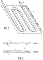
- the path followed by the heating element in the plane varies according to the modes of execution. It can be a circular path, a path in serpentine, oval or any shape. It is also possible to provide several heating elements, arranged for example side by side or still in concentric circles.
- plates are used not preformed.
- the strike then has the effect of causing a partial movement material around the heating element and / or to penetrate at least partially the heating element in the diffusing plate.
- one or more grooves 3 are then preformed in the plates in question, so as to form a housing in which rests at minus a portion of the radial section of the corresponding heating element.
- the groove path is advantageously similar to that of the element corresponding heater.
- the striking dies 10 are advantageously shaped as a function of the desired final outline of the whole. It is therefore advantageous to preform the grooves in the diffusing plate according to the desired final contour. Under the effect of striking, the material of the diffusing plate fills the portion of the groove initially left free by the heating element, so as to surround at at least partially this one.
- the striking tool is advantageously shaped with a groove whose shape advantageously corresponds to the profile of the element heating.
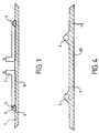
- the grooves 3 or 3 ' are shaped and arranged so as to minimize the deformations undergone by the casing 5 (fig. 1 and 1 ') of the heating element 4 so that these deformations remain within acceptable limits, in particular in the purpose of avoiding any short circuit between the casing 5 and the core 6 of the element heating 4.
- the diffusing plate 1 plays in particular a role of conduction and distribution of thermal energy. In this way, thanks to a larger surface of transmission, avoiding unfavorable local overheating zones. For this reason, it is advantageous to use a material having good thermal conductivity characteristics.
- the diffusing plate can fulfill a multiplicity of other functions. So it can be a plate substantially flat serving for example as a support on which a object intended to be heated, such as for example a cooking vessel. he can also be the bottom of a container. In this case, the outline of the plate can be shaped to serve as walls for the container.
- the plate can also be juxtaposed to another element, itself serving as the bottom of a container.
- This variant allows to adapt with a great ease the heating assembly according to the invention to a multiplicity elements, in particular in order to obtain heating characteristics optimal.
- the diffusing plate makes it possible in particular to transmit the thermal energy generated by the heating element from it towards the free surface 9 of the diffusing plate 1.
- the electric heating unit can also be configured according to other types of applications, to serve for example as a heating panel. In such a case, it is advantageous to isolate the external face of the plate 2 and provide a support means allowing the assembly to be arranged vertically.
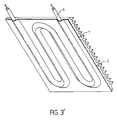
- the free face 9 of the diffusing plate 1 is then advantageously configured to in order to optimize the heat transmission surface, for example with a profile with a series of fins, as illustrated in Figure 3.
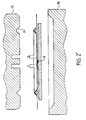
- the assembly electric heater is configured to form the body of an iron soleplate to redo.
- the conductive material for example a aluminum alloy
- the conductive material for example a aluminum alloy
- Plate 20 arranged against the free face 12 of the diffusing plate and struck simultaneously with the other elements of the whole serves as a sole.
- the ends 7 (fig. 1) of the heating element can be folded in a direction opposite to plate 1 and thus move away from the assembly.
- the tips thus arranged can be used for a standard type connection.
- the tips 7 can also extend in the plane of the assembly for exit by the side of it.
- the hitting dies are then provided with clearances to avoid any damage that could be caused to said tips.
- sensors in particular temperature sensors, enabling regulation and / or the safety of the heating assembly.
- sensors of known type, can be inserted between plates 1 and 2, for example near the heating element.
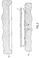
- Figure 2 illustrates the process used to assemble the different elements constituents of the electric heating assembly according to the invention.
- an assembly consisting of a plate 1 is used and at least a heating element 4, the plate whether or not comprising one or more grooves 3 preformed.
- the hot stamping is then carried out.
- This hot stamping is advantageously carried out at a temperature allowing optimal creep of the material constituting the diffusing plate 1.
- this temperature is between 400 ° C and 500 ° C and preferably around 455 ° C.
- the assembly of the different elements by hot stamping allows the whole is maintained by an intimate mechanical connection between the diffusing plate 1 and the adjoining portion of the heating elements 4.
- Figure 1 illustrates the result obtained with an element heater of substantially triangular section. In this case, the material of the plate 1, after creep, partially surrounds the edges of the heating element.
- Figure 4 illustrates the result obtained with a heating element of substantially circular section arranged against a plate forming a sole of iron.
- Hot stamping therefore has a multiple effect: strong cohesion between the heating element 4 and the adjacent portion of the diffusing plate 1, in particular the portion of the groove 3 filled by creep of the material of the diffusing plate.
- the resulting electric heating assembly therefore has a very large cohesion. It is also strong, stable and durable.
- the simplicity and the speed of the hot stamping process allows a wide range to be obtained of different embodiments, at a very advantageous cost.
- the process of hot typing also lends itself well to automation.
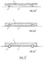
- a second advantageous embodiment of the invention is illustrated in Figures 1 'to 5'.
- the elements corresponding to those of Figures 1 to 5 have the same reference numbers.
- a cover plate 2 is arranged against the first plate, so as to cover the heating element. It is a plate made of a harder alloy than that of the plate diffusing 1, so as to promote the creep of the plate 1 during assembly, as described below. So we use a metal plate 2 advantageously made of steel.
- the cover plate advantageously occupies the entire covered area by the diffusing plate. It can extend more or less over the sides, as shown in Figure 1 ', so as to allow the formation of an edge 11 by example. It can also cover a smaller area and / or present openings or clearances where the plate 1 is free. We obtain then only a partial covering of the plate 1. According to various modes of realization, it is also possible to provide several plates of cover 2 arranged on the side of the heating element and / or even against the free face 9 of the diffusing plate 1 as described later in the example of an iron soleplate.
- one or more grooves 3 are then preformed in the or the plates in question, so as to form a housing in which rests at least a portion of the radial section of the corresponding heating element.
- the path of the groove is advantageously similar to that of the element corresponding heater. If you use a rather rigid cover plate and thick, the preformed grooves have the advantage of protecting the heating element placed in this groove during striking.
- the striking dies 10 are advantageously shaped as a function of the desired final contour of the cover plate and of the whole assembly. It is therefore advantageous to preform the grooves 3 'in the image of the desired final contour.
- the heating element benefits from a protection minimizing the deformations it could undergo during typing, since the plate of covering is for all practical purposes not distorted during typing.
- non-preformed plates are used. It is then advantageous to use a thinner and / or more cover plate flexible, so as to allow this plate to follow the contour of the element heating and / or the one provided on the impact die, avoiding deterioration the heating element when typing. So, especially in the case of the figure 5a ', where no groove is preformed in the plates of the assembly, the strike 10 is advantageously shaped with a groove 3 'whose shape advantageously corresponds to the profile of the heating element.
- the groove is provided in the diffusing plate.
- the grooves 3 or 3 ' are shaped and arranged so as to minimize the deformations undergone by the casing 5 of the heating element 4 so that these deformations remain within acceptable limits, in particular for the purpose avoid any short circuit between the casing 5 and the core 6 of the heating element 4.
- the material of the diffusing plate fills the portion of the groove initially left free by the heating element, so as to surround at at least partially this one.
- the diffusing plate 1 plays in particular a role of conduction and distribution of thermal energy. In this way, thanks to a larger surface of transmission, avoiding unfavorable local overheating zones. For this reason, it is advantageous to use a material having good thermal conductivity characteristics. Given the holding effect provided by the addition of at least one attached plate, it is possible to make a heating assembly comprising several diffusing plates 1 juxtaposed to each other. The plates are then preferably placed close immediately relative to each other, or so as to be in contact with each other with the other.
- the electric heating assembly is configured so as to form the body of an iron soleplate.
- the material conductor for example an aluminum alloy, is advantageously arranged between two cover plates 2 and 20, for example made of stainless steel.
- the plate 2 plays a role similar to that described above.
- a sole plate of a known type whose sliding properties and wear resistance are advantageous. It is also possible to fix the plate 20 after striking, for example by gluing, riveting or screwing.
- the ends 7 of the heating element can be folded in a direction opposite plate 1 and exit from the assembly through holes or grooves specially provided for this purpose in the cover plate.
- the tips thus arranged can be used for a standard type connection.
- the tips 7 can also extend in the plane of the assembly for exit by the side of it.
- the hitting dies are provided with clearances to avoid any damage that could be caused to said tips.
- sensors in particular temperature sensors, enabling regulation and / or the safety of the heating assembly.
- sensors of known type, can be inserted between plates 1 and 2, for example near the element heating.
- Figure 2 Illustrates the process used for assembling the different elements constituents of the electric heating assembly according to the invention.
- a set of plates 1 and 2 is used and at least one heating element 4, the plates optionally comprising one or more grooves 3 preformed.
- the hot stamping is then carried out.
- This hot stamping is advantageously carried out at a temperature allowing optimal creep of the material constituting the diffusing plate 1.
- this temperature is between 400 ° C and 500 ° C and preferably around 455 ° C.
- the minimum pressure exerted during striking is advantageously around 250 N / mm 2 and the striking speed is generally at least 0.30 m / s.
- the assembly of the different elements by hot stamping allows the whole either maintained by an intimate mechanical connection between on the one hand the plate diffusing 1 and the cover plate 2 and on the other hand between the portion adjacent to the plate 1 and the heating element (s) 4.
- Hot stamping therefore has a multiple effect: on the one hand, strong cohesion between the diffusing plates 1 and the covering plates 2 and / or 20 reported; on the other hand, strong cohesion between the heating element 4 and the adjacent portion of the diffusing plate 1, in particular the portion of the groove 3 filled by creep of the material of the diffusing plate.
- This cohesive force also provides an additional clamping effect on the element heater 4 fixedly held between the portion of the cover plate 2 partially surrounding it and the adjacent portion of the diffusing plate 1.
- the resulting electric heating assembly therefore has a very large cohesion. It is also strong, stable and durable.
- the simplicity and the speed of the hot stamping process allows a wide range to be obtained of different embodiments, at a very advantageous cost.
- the process of hot typing also lends itself well to automation.
- the assembly process and the electric heating assembly according to the invention therefore make it possible to obtain, for example, a heating base or a thermal diffuser which can be regulated according to several heating stages, offering high thermal efficiency and optimal heat distribution and able to support significant powers without decohesion of the assembly long-term.
- the shapes and dimensions of the heating assembly may vary depending on of the whole range of corresponding applications.
- the invention finds its application in the production of heating assemblies electric.
Claims (17)
- Verfahren zur Montage einer elektrischen Heizgruppe mit wenigstens einer Verteilerplatte (1) aus metallischem Material und wenigstens einem Heizelement (4), das an der oder den besagten Verteilerplatte(n) (1) angeordnet ist, dadurch gekennzeichnet, daß es eine Warmstauchung umfaßt, die auf die elektrische Heizgruppe ausgeübt wird, nachdem die Heizelemente an der oder den Verteilerplatte(n) (1) angeordnet wurden, wobei diese Warmstauchung bei einer Temperatur, einem Druck und mit einer Stauchgeschwindigkeit durchgeführt wird, die ein plastisches Fließen des Materials der Verteilerplatte (1) ermöglichen, was einen Zusammenhalt zwischen dem Heizelement und der besagten Verteilerplatte (1) bewirkt.
- Verfahren zur Montage einer elektrischen Heizgruppe nach Anspruch 1, bei dem besagte Fließtemperatur zwischen 400°C und 500°C und vorzugsweise um 455°C liegt.
- Verfahren zur Montage einer elektrischen Heizgruppe nach einem der Ansprüche 1 und 2, bei dem die Warmstauchung mit einem Mindestdruck durchgeführt wird, der um 250 N/mm2 liegt.
- Verfahren zur Montage einer elektrischen Heizgruppe nach einem der Ansprüche 1 bis 3, bei dem die Warmstauchung mit einer Mindestgeschwindigkeit von 0.30 m/s durchgeführt wird.
- Verfahren zur Montage einer elektrischen Heizgruppe nach einem der Ansprüche 1 bis 4, bei dem wenigstens zwei der wesentlichen Elemente der Gruppe vor der Warmstauchung durch Löten (8), Kleben oder Quetschverbinden vorpositioniert oder vormontiert sind.
- Verfahren zur Montage einer elektrischen Heizgruppe nach einem der Ansprüche 1 bis 5, das die folgenden vorbereitenden Schritte umfaßt:wenigstens eine Rille (3,3'), der wenigstens eines der besagten Heizelemente (4) zugeordnet ist, wird in wenigstens einem Abschnitt der besagten Verteilerplatte(n) (1) und/oder im Stauchwerkzeug (10) vorgeformt,jedes einer gegebenen Rille (3,3') zugeordnete Heizelement (4) ist an den entsprechenden Verteilerplatten (1) angeordnet, so daß es entlang einer Bahn verläuft, die im wesentlichen derjenigen der entsprechenden Rille gleicht.
- Verfahren zur Montage einer elektrischen Heizgruppe nach einem der Ansprüche 1 bis 5, wobei die besagte Gruppe ebenfalls wenigstens eine Abdeckplatte (2;20) enthält, das die folgenden Schritte umfaßt:die Heizelemente (4) sind zwischen zum einen den Verteilerplatten (1) und zum anderen den Abdeckplatten (2) angeordnet,die Gruppe wird einer Warmstauchung unterzogen.
- Verfahren zur Montage einer elektrischen Heizgruppe nach Anspruch 7, das die folgenden vorbereitenden Schritte umfaßt:wenigstens eine Rille (3,3'), der wenigstens eines der besagten Heizelemente (4) zugeordnet ist, wird in wenigstens einem Abschnitt der besagten Abdeckplatte(n) (2) und/oder in wenigstens einem Abschnitt der besagten Verteilerplatte(n) (1) und/oder im Stauchwerkzeug (10) vorgeformt,jedes einer gegebenen Rille (3,3') zugeordnete Heizelement (4) ist zwischen den Abdeckplatten (2) und den entsprechenden Verteilerplatten (1) so angeordnet, daß es entlang einer Bahn verläuft, die im wesentlichen derjenigen der entsprechenden Rille (3,3') gleicht.
- Verfahren zur Montage einer elektrischen Heizgruppe nach einem der Ansprüche 1, 2, 3, 4, 5 und 7, bei dem das Material der Verteilerplatte (1) unter der Wirkung der Stauchung wenigstens teilweise durch plastisches Fließen dieses Materials um die Heizelemente (4) herum gelangt.
- Verfahren zur Montage einer elektrischen Heizgruppe nach einem der Ansprüche 6 und 8, bei dem das Material der Verteilerplatte unter der Wirkung der Stauchung den Teil der Rille (3,3'), der vom Heizelement (4) frei gelassen wurde, so auffüllt, daß es dieses wenigstens teilweise umgibt.
- Verfahren zur Montage einer elektrischen Heizgruppe nach einem der Ansprüche 6 und 8, bei dem die besagten Rillen (3,3') so gestaltet sind, daß sie eine Form aufweisen, die im wesentlichen dem Profil des zugeordneten Heizelements (4) entspricht.
- Elektrische Heizgruppe, die durch ein Verfahren nach einem der Ansprüche 1 bis 11 erhalten wird.
- Elektrisches Haushaltsgerät, das eine elektrische Heizgruppe nach Anspruch 12 enthält.
- Elektrisches Haushaltsgerät nach Anspruch 13, das aus einem Kochgerät besteht.
- Elektrisches Haushaltsgerät nach Anspruch 13, das aus einer Vorrichtung besteht, die zum Heizen einer Flüssigkeit, insbesondere von Wasser, bestimmt ist.
- Elektrisches Haushaltsgerät nach Anspruch 13, das aus einem Strahlungsheizkörper besteht.
- Elektrisches Haushaltsgerät nach Anspruch 13, das aus einer Vorrichtung zum Bügeln, insbesondere einer Sohle eines Bügeleisens, besteht.
Applications Claiming Priority (5)
| Application Number | Priority Date | Filing Date | Title |
|---|---|---|---|
| FR9501348 | 1995-02-01 | ||
| FR9501348A FR2730120B1 (fr) | 1995-02-01 | 1995-02-01 | Element chauffant avec plaque diffusante |
| FR9501347A FR2730119B1 (fr) | 1995-02-01 | 1995-02-01 | Ensemble chauffant electrique |
| FR9501347 | 1995-10-13 | ||
| PCT/FR1996/000167 WO1996024233A1 (fr) | 1995-02-01 | 1996-01-31 | Element chauffant avec plaque diffusante et procede d'assemblage dudit ensemble |
Publications (2)
| Publication Number | Publication Date |
|---|---|
| EP0807367A1 EP0807367A1 (de) | 1997-11-19 |
| EP0807367B1 true EP0807367B1 (de) | 2000-04-26 |
Family
ID=26231740
Family Applications (1)
| Application Number | Title | Priority Date | Filing Date |
|---|---|---|---|
| EP96902320A Expired - Lifetime EP0807367B1 (de) | 1995-02-01 | 1996-01-31 | Heizelement mit streuscheibe und verfahren zum zusammenbauen der beiden |
Country Status (10)
| Country | Link |
|---|---|
| EP (1) | EP0807367B1 (de) |
| JP (1) | JPH10513303A (de) |
| KR (1) | KR19980701703A (de) |
| CN (1) | CN1172574A (de) |
| AU (1) | AU4667696A (de) |
| BR (1) | BR9607163A (de) |
| DE (1) | DE69607939T2 (de) |
| ES (1) | ES2147916T3 (de) |
| GR (1) | GR3033778T3 (de) |
| WO (1) | WO1996024233A1 (de) |
Families Citing this family (7)
| Publication number | Priority date | Publication date | Assignee | Title |
|---|---|---|---|---|
| FR2762531B1 (fr) * | 1997-04-28 | 1999-08-13 | Superba Sa | Appareil portable omnidirectionnel de nettoyage a la vapeur de surfaces dures ou souples |
| US7121024B1 (en) | 2005-10-17 | 2006-10-17 | Suzanne T Clevenberg | Creaser steam iron |
| EP2213784B1 (de) * | 2009-01-30 | 2015-03-11 | Polne, S.L. | Grundplatte und Eisen, das eine solche Grundplatte umfasst |
| CN104080213A (zh) * | 2013-03-29 | 2014-10-01 | 宁波吉毅电器有限公司 | 一种铝板式快速散热电加热器 |
| CN104219801A (zh) * | 2013-05-29 | 2014-12-17 | 宁波吉毅电器有限公司 | 一种新型快速散热电加热器 |
| US10081905B2 (en) | 2014-01-09 | 2018-09-25 | Modiron, LLC | Ironing device |
| FR3033679A1 (fr) | 2015-03-11 | 2016-09-16 | Fanien Hubert Jean Louis Henri Delelis | Procede d'assemblage d'element chauffant de type plaque et article chauffant s'y rapportant |
Family Cites Families (7)
| Publication number | Priority date | Publication date | Assignee | Title |
|---|---|---|---|---|
| US2851572A (en) * | 1957-05-13 | 1958-09-09 | Raybestos Manhattan Inc | Heating unit |
| US3221396A (en) * | 1960-07-15 | 1965-12-07 | Gen Motors Corp | Method of forming a solid plate cooking unit |
| US3581144A (en) * | 1969-03-27 | 1971-05-25 | Gen Electric | Metal-clad insulated electrical heater |
| GB1395011A (en) * | 1973-08-24 | 1975-05-21 | Suhl Elektrogeraete Veb K | Fastening of tubes containing heating elements on a carrier plate |
| DE2461249A1 (de) * | 1974-12-23 | 1976-06-24 | Elpag Ag Chur | Verfahren zum befestigen von verbindungsgliedern mit einem metallteil |
| US4045653A (en) * | 1976-06-28 | 1977-08-30 | National Presto Industries, Inc. | Electric cooker with press-staked heating element and method of making the same |
| GB1590836A (en) * | 1977-11-21 | 1981-06-10 | Ass Eng Ltd | Electrically heated apparatus |
-
1996
- 1996-01-31 JP JP8523318A patent/JPH10513303A/ja active Pending
- 1996-01-31 WO PCT/FR1996/000167 patent/WO1996024233A1/fr not_active Application Discontinuation
- 1996-01-31 BR BR9607163A patent/BR9607163A/pt not_active Application Discontinuation
- 1996-01-31 AU AU46676/96A patent/AU4667696A/en not_active Abandoned
- 1996-01-31 CN CN96191728A patent/CN1172574A/zh active Pending
- 1996-01-31 KR KR1019970705099A patent/KR19980701703A/ko not_active Application Discontinuation
- 1996-01-31 ES ES96902320T patent/ES2147916T3/es not_active Expired - Lifetime
- 1996-01-31 DE DE69607939T patent/DE69607939T2/de not_active Expired - Fee Related
- 1996-01-31 EP EP96902320A patent/EP0807367B1/de not_active Expired - Lifetime
-
2000
- 2000-06-23 GR GR20000401475T patent/GR3033778T3/el not_active IP Right Cessation
Also Published As
| Publication number | Publication date |
|---|---|
| KR19980701703A (ko) | 1998-06-25 |
| WO1996024233A1 (fr) | 1996-08-08 |
| AU4667696A (en) | 1996-08-21 |
| BR9607163A (pt) | 1997-11-11 |
| JPH10513303A (ja) | 1998-12-15 |
| MX9705805A (es) | 1998-07-31 |
| CN1172574A (zh) | 1998-02-04 |
| DE69607939D1 (de) | 2000-05-31 |
| EP0807367A1 (de) | 1997-11-19 |
| GR3033778T3 (en) | 2000-10-31 |
| DE69607939T2 (de) | 2000-11-09 |
| ES2147916T3 (es) | 2000-10-01 |
Similar Documents
| Publication | Publication Date | Title |
|---|---|---|
| EP0648459B1 (de) | Kochtopf mit beherrschter Verformung des Topfbodens | |
| FR2718936A1 (fr) | Ustensile de cuisine avec structure à fond multiple et méthode de fabrication dudit ustensile de cuisine. | |
| EP0807367B1 (de) | Heizelement mit streuscheibe und verfahren zum zusammenbauen der beiden | |
| EP0668040A1 (de) | Kochgefäss mit verstärktem Boden und dessen Herstellung | |
| EP1033929B1 (de) | Elektrisches kochgerät, insbesondere ein fritiergerät, mit einem flachen heizelement mit durch siebdruck hergestelltem widerstand | |
| EP1496778B1 (de) | Kochgerät bei dem der mantel des behälterbodens ein verzierungselement umfasst und dazugehörendes herstellungsverfahren | |
| CA2244503C (fr) | Dispositif de fixation de pieces d'un appareil electromenager | |
| EP0035456B1 (de) | Heizfläche, insbesondere zum Kochen, mit einem elektrischen Heizwiderstand, Verfahren zu ihrer Herstellung | |
| FR2730120A1 (fr) | Element chauffant avec plaque diffusante | |
| FR2730119A1 (fr) | Ensemble chauffant electrique | |
| FR2741553A1 (fr) | Procede de fabrication d'un recipient de cuisson et recipient obtenu | |
| WO2007006978A1 (fr) | Ustensile de cuisson | |
| EP1557120B1 (de) | Haube von einem elektronischen Waffeleisen | |
| FR2628283A1 (fr) | Composant chauffant plat a element chauffant electriquement resistant et son procede de fabrication | |
| EP1400194B1 (de) | Heizbaugruppe eines elektrischen Apparates vom Typ eines Waffeleisens | |
| EP0713937B1 (de) | Bügeleisen Sohle | |
| WO2006040476A1 (fr) | Element chauffant, notamment destine aux bouilloires | |
| EP0739153B1 (de) | Auf einem Träger hartaufgelötetes Heizelement | |
| FR2705374A1 (fr) | Semelle pour un fer à repasser électrique. | |
| FR2711050A1 (fr) | Récipient à cuisson à fond indéformable. | |
| FR2705218A3 (fr) | Appareil de cuisson à chauffage électrique, en particulier friteuse. | |
| EP3068188A1 (de) | Verfahren zum zusammenbau von heizelementen vom typ heizplatte und dazugehörigen heizartikeln | |
| CH246444A (fr) | Plaque chauffante pour cuisinière et autres appareils de chauffage électrique, et procédé pour sa fabrication. | |
| BE529094A (de) |
Legal Events
| Date | Code | Title | Description |
|---|---|---|---|
| PUAI | Public reference made under article 153(3) epc to a published international application that has entered the european phase |
Free format text: ORIGINAL CODE: 0009012 |
|
| 17P | Request for examination filed |
Effective date: 19970718 |
|
| AK | Designated contracting states |
Kind code of ref document: A1 Designated state(s): BE DE ES FR GB GR IT NL PT |
|
| 17Q | First examination report despatched |
Effective date: 19971128 |
|
| GRAG | Despatch of communication of intention to grant |
Free format text: ORIGINAL CODE: EPIDOS AGRA |
|
| GRAG | Despatch of communication of intention to grant |
Free format text: ORIGINAL CODE: EPIDOS AGRA |
|
| GRAH | Despatch of communication of intention to grant a patent |
Free format text: ORIGINAL CODE: EPIDOS IGRA |
|
| GRAH | Despatch of communication of intention to grant a patent |
Free format text: ORIGINAL CODE: EPIDOS IGRA |
|
| GRAA | (expected) grant |
Free format text: ORIGINAL CODE: 0009210 |
|
| AK | Designated contracting states |
Kind code of ref document: B1 Designated state(s): BE DE ES FR GB GR IT NL PT |
|
| PG25 | Lapsed in a contracting state [announced via postgrant information from national office to epo] |
Ref country code: NL Free format text: LAPSE BECAUSE OF FAILURE TO SUBMIT A TRANSLATION OF THE DESCRIPTION OR TO PAY THE FEE WITHIN THE PRESCRIBED TIME-LIMIT Effective date: 20000426 |
|
| REF | Corresponds to: |
Ref document number: 69607939 Country of ref document: DE Date of ref document: 20000531 |
|
| GBT | Gb: translation of ep patent filed (gb section 77(6)(a)/1977) |
Effective date: 20000615 |
|
| ITF | It: translation for a ep patent filed |
Owner name: MAROSCIA & ASSOCIATI S.R.L. |
|
| PG25 | Lapsed in a contracting state [announced via postgrant information from national office to epo] |
Ref country code: PT Free format text: LAPSE BECAUSE OF FAILURE TO SUBMIT A TRANSLATION OF THE DESCRIPTION OR TO PAY THE FEE WITHIN THE PRESCRIBED TIME-LIMIT Effective date: 20000726 |
|
| REG | Reference to a national code |
Ref country code: ES Ref legal event code: FG2A Ref document number: 2147916 Country of ref document: ES Kind code of ref document: T3 |
|
| NLV1 | Nl: lapsed or annulled due to failure to fulfill the requirements of art. 29p and 29m of the patents act | ||
| PGFP | Annual fee paid to national office [announced via postgrant information from national office to epo] |
Ref country code: GR Payment date: 20001130 Year of fee payment: 6 |
|
| PGFP | Annual fee paid to national office [announced via postgrant information from national office to epo] |
Ref country code: BE Payment date: 20001204 Year of fee payment: 6 |
|
| PGFP | Annual fee paid to national office [announced via postgrant information from national office to epo] |
Ref country code: GB Payment date: 20010131 Year of fee payment: 6 |
|
| PLBE | No opposition filed within time limit |
Free format text: ORIGINAL CODE: 0009261 |
|
| STAA | Information on the status of an ep patent application or granted ep patent |
Free format text: STATUS: NO OPPOSITION FILED WITHIN TIME LIMIT |
|
| 26N | No opposition filed | ||
| REG | Reference to a national code |
Ref country code: GB Ref legal event code: IF02 |
|
| PG25 | Lapsed in a contracting state [announced via postgrant information from national office to epo] |
Ref country code: GB Free format text: LAPSE BECAUSE OF NON-PAYMENT OF DUE FEES Effective date: 20020131 Ref country code: BE Free format text: LAPSE BECAUSE OF NON-PAYMENT OF DUE FEES Effective date: 20020131 |
|
| BERE | Be: lapsed |
Owner name: S.A. SEB Effective date: 20020131 |
|
| PG25 | Lapsed in a contracting state [announced via postgrant information from national office to epo] |
Ref country code: GR Free format text: LAPSE BECAUSE OF NON-PAYMENT OF DUE FEES Effective date: 20020812 |
|
| GBPC | Gb: european patent ceased through non-payment of renewal fee |
Effective date: 20020131 |
|
| PGFP | Annual fee paid to national office [announced via postgrant information from national office to epo] |
Ref country code: ES Payment date: 20030115 Year of fee payment: 8 |
|
| PGFP | Annual fee paid to national office [announced via postgrant information from national office to epo] |
Ref country code: DE Payment date: 20030331 Year of fee payment: 8 |
|
| PGFP | Annual fee paid to national office [announced via postgrant information from national office to epo] |
Ref country code: FR Payment date: 20031216 Year of fee payment: 9 |
|
| PG25 | Lapsed in a contracting state [announced via postgrant information from national office to epo] |
Ref country code: ES Free format text: LAPSE BECAUSE OF NON-PAYMENT OF DUE FEES Effective date: 20040202 |
|
| PG25 | Lapsed in a contracting state [announced via postgrant information from national office to epo] |
Ref country code: DE Free format text: LAPSE BECAUSE OF NON-PAYMENT OF DUE FEES Effective date: 20040803 |
|
| PG25 | Lapsed in a contracting state [announced via postgrant information from national office to epo] |
Ref country code: IT Free format text: LAPSE BECAUSE OF NON-PAYMENT OF DUE FEES Effective date: 20050131 |
|
| REG | Reference to a national code |
Ref country code: ES Ref legal event code: FD2A Effective date: 20040202 |
|
| PG25 | Lapsed in a contracting state [announced via postgrant information from national office to epo] |
Ref country code: FR Free format text: LAPSE BECAUSE OF NON-PAYMENT OF DUE FEES Effective date: 20050930 |
|
| REG | Reference to a national code |
Ref country code: FR Ref legal event code: ST |