EP0789360A2 - Data recording and reproduction - Google Patents
Data recording and reproduction Download PDFInfo
- Publication number
- EP0789360A2 EP0789360A2 EP97300629A EP97300629A EP0789360A2 EP 0789360 A2 EP0789360 A2 EP 0789360A2 EP 97300629 A EP97300629 A EP 97300629A EP 97300629 A EP97300629 A EP 97300629A EP 0789360 A2 EP0789360 A2 EP 0789360A2
- Authority
- EP
- European Patent Office
- Prior art keywords
- data
- recording medium
- buffer memory
- reproduced
- reproduction
- Prior art date
- Legal status (The legal status is an assumption and is not a legal conclusion. Google has not performed a legal analysis and makes no representation as to the accuracy of the status listed.)
- Granted
Links
Images


Classifications
-
- G—PHYSICS
- G11—INFORMATION STORAGE
- G11B—INFORMATION STORAGE BASED ON RELATIVE MOVEMENT BETWEEN RECORD CARRIER AND TRANSDUCER
- G11B20/00—Signal processing not specific to the method of recording or reproducing; Circuits therefor
- G11B20/10—Digital recording or reproducing
- G11B20/12—Formatting, e.g. arrangement of data block or words on the record carriers
-
- G—PHYSICS
- G11—INFORMATION STORAGE
- G11B—INFORMATION STORAGE BASED ON RELATIVE MOVEMENT BETWEEN RECORD CARRIER AND TRANSDUCER
- G11B19/00—Driving, starting, stopping record carriers not specifically of filamentary or web form, or of supports therefor; Control thereof; Control of operating function ; Driving both disc and head
- G11B19/02—Control of operating function, e.g. switching from recording to reproducing
-
- G—PHYSICS
- G11—INFORMATION STORAGE
- G11B—INFORMATION STORAGE BASED ON RELATIVE MOVEMENT BETWEEN RECORD CARRIER AND TRANSDUCER
- G11B20/00—Signal processing not specific to the method of recording or reproducing; Circuits therefor
- G11B20/00086—Circuits for prevention of unauthorised reproduction or copying, e.g. piracy
- G11B20/00572—Circuits for prevention of unauthorised reproduction or copying, e.g. piracy involving measures which change the format of the recording medium
- G11B20/00615—Circuits for prevention of unauthorised reproduction or copying, e.g. piracy involving measures which change the format of the recording medium said format change concerning the logical format of the recording medium, e.g. the structure of sectors, blocks, or frames
-
- G—PHYSICS
- G11—INFORMATION STORAGE
- G11B—INFORMATION STORAGE BASED ON RELATIVE MOVEMENT BETWEEN RECORD CARRIER AND TRANSDUCER
- G11B20/00—Signal processing not specific to the method of recording or reproducing; Circuits therefor
- G11B20/10—Digital recording or reproducing
- G11B20/10527—Audio or video recording; Data buffering arrangements
-
- G—PHYSICS
- G11—INFORMATION STORAGE
- G11B—INFORMATION STORAGE BASED ON RELATIVE MOVEMENT BETWEEN RECORD CARRIER AND TRANSDUCER
- G11B20/00—Signal processing not specific to the method of recording or reproducing; Circuits therefor
- G11B20/10—Digital recording or reproducing
- G11B20/12—Formatting, e.g. arrangement of data block or words on the record carriers
- G11B20/1217—Formatting, e.g. arrangement of data block or words on the record carriers on discs
- G11B20/1254—Formatting, e.g. arrangement of data block or words on the record carriers on discs for mixed data, i.e. continuous and discontinuous data
-
- G—PHYSICS
- G11—INFORMATION STORAGE
- G11B—INFORMATION STORAGE BASED ON RELATIVE MOVEMENT BETWEEN RECORD CARRIER AND TRANSDUCER
- G11B20/00—Signal processing not specific to the method of recording or reproducing; Circuits therefor
- G11B20/10—Digital recording or reproducing
- G11B20/18—Error detection or correction; Testing, e.g. of drop-outs
- G11B20/1866—Error detection or correction; Testing, e.g. of drop-outs by interleaving
-
- G—PHYSICS
- G11—INFORMATION STORAGE
- G11B—INFORMATION STORAGE BASED ON RELATIVE MOVEMENT BETWEEN RECORD CARRIER AND TRANSDUCER
- G11B27/00—Editing; Indexing; Addressing; Timing or synchronising; Monitoring; Measuring tape travel
- G11B27/02—Editing, e.g. varying the order of information signals recorded on, or reproduced from, record carriers
- G11B27/031—Electronic editing of digitised analogue information signals, e.g. audio or video signals
- G11B27/034—Electronic editing of digitised analogue information signals, e.g. audio or video signals on discs
-
- G—PHYSICS
- G11—INFORMATION STORAGE
- G11B—INFORMATION STORAGE BASED ON RELATIVE MOVEMENT BETWEEN RECORD CARRIER AND TRANSDUCER
- G11B27/00—Editing; Indexing; Addressing; Timing or synchronising; Monitoring; Measuring tape travel
- G11B27/10—Indexing; Addressing; Timing or synchronising; Measuring tape travel
- G11B27/102—Programmed access in sequence to addressed parts of tracks of operating record carriers
- G11B27/105—Programmed access in sequence to addressed parts of tracks of operating record carriers of operating discs
-
- H—ELECTRICITY
- H04—ELECTRIC COMMUNICATION TECHNIQUE
- H04N—PICTORIAL COMMUNICATION, e.g. TELEVISION
- H04N9/00—Details of colour television systems
- H04N9/79—Processing of colour television signals in connection with recording
- H04N9/80—Transformation of the television signal for recording, e.g. modulation, frequency changing; Inverse transformation for playback
- H04N9/804—Transformation of the television signal for recording, e.g. modulation, frequency changing; Inverse transformation for playback involving pulse code modulation of the colour picture signal components
- H04N9/8042—Transformation of the television signal for recording, e.g. modulation, frequency changing; Inverse transformation for playback involving pulse code modulation of the colour picture signal components involving data reduction
-
- G—PHYSICS
- G11—INFORMATION STORAGE
- G11B—INFORMATION STORAGE BASED ON RELATIVE MOVEMENT BETWEEN RECORD CARRIER AND TRANSDUCER
- G11B20/00—Signal processing not specific to the method of recording or reproducing; Circuits therefor
- G11B20/00086—Circuits for prevention of unauthorised reproduction or copying, e.g. piracy
- G11B20/00137—Circuits for prevention of unauthorised reproduction or copying, e.g. piracy involving measures which result in a restriction to contents recorded on or reproduced from a record carrier to authorised users
- G11B20/00159—Parental control systems
-
- G—PHYSICS
- G11—INFORMATION STORAGE
- G11B—INFORMATION STORAGE BASED ON RELATIVE MOVEMENT BETWEEN RECORD CARRIER AND TRANSDUCER
- G11B20/00—Signal processing not specific to the method of recording or reproducing; Circuits therefor
- G11B20/10—Digital recording or reproducing
- G11B20/10527—Audio or video recording; Data buffering arrangements
- G11B2020/1062—Data buffering arrangements, e.g. recording or playback buffers
- G11B2020/10629—Data buffering arrangements, e.g. recording or playback buffers the buffer having a specific structure
- G11B2020/10666—Ring buffers, e.g. buffers wherein an iteratively progressing read or write pointer moves back to the beginning of the buffer when reaching the last storage cell
-
- G—PHYSICS
- G11—INFORMATION STORAGE
- G11B—INFORMATION STORAGE BASED ON RELATIVE MOVEMENT BETWEEN RECORD CARRIER AND TRANSDUCER
- G11B20/00—Signal processing not specific to the method of recording or reproducing; Circuits therefor
- G11B20/10—Digital recording or reproducing
- G11B20/10527—Audio or video recording; Data buffering arrangements
- G11B2020/1062—Data buffering arrangements, e.g. recording or playback buffers
- G11B2020/10805—Data buffering arrangements, e.g. recording or playback buffers involving specific measures to prevent a buffer overflow
-
- G—PHYSICS
- G11—INFORMATION STORAGE
- G11B—INFORMATION STORAGE BASED ON RELATIVE MOVEMENT BETWEEN RECORD CARRIER AND TRANSDUCER
- G11B20/00—Signal processing not specific to the method of recording or reproducing; Circuits therefor
- G11B20/10—Digital recording or reproducing
- G11B20/10527—Audio or video recording; Data buffering arrangements
- G11B2020/1062—Data buffering arrangements, e.g. recording or playback buffers
- G11B2020/10814—Data buffering arrangements, e.g. recording or playback buffers involving specific measures to prevent a buffer underrun
-
- G—PHYSICS
- G11—INFORMATION STORAGE
- G11B—INFORMATION STORAGE BASED ON RELATIVE MOVEMENT BETWEEN RECORD CARRIER AND TRANSDUCER
- G11B20/00—Signal processing not specific to the method of recording or reproducing; Circuits therefor
- G11B20/10—Digital recording or reproducing
- G11B20/12—Formatting, e.g. arrangement of data block or words on the record carriers
- G11B20/1217—Formatting, e.g. arrangement of data block or words on the record carriers on discs
- G11B2020/1218—Formatting, e.g. arrangement of data block or words on the record carriers on discs wherein the formatting concerns a specific area of the disc
- G11B2020/1222—ECC block, i.e. a block of error correction encoded symbols which includes all parity data needed for decoding
-
- G—PHYSICS
- G11—INFORMATION STORAGE
- G11B—INFORMATION STORAGE BASED ON RELATIVE MOVEMENT BETWEEN RECORD CARRIER AND TRANSDUCER
- G11B2220/00—Record carriers by type
- G11B2220/20—Disc-shaped record carriers
-
- H—ELECTRICITY
- H04—ELECTRIC COMMUNICATION TECHNIQUE
- H04N—PICTORIAL COMMUNICATION, e.g. TELEVISION
- H04N5/00—Details of television systems
- H04N5/76—Television signal recording
- H04N5/84—Television signal recording using optical recording
- H04N5/85—Television signal recording using optical recording on discs or drums
-
- H—ELECTRICITY
- H04—ELECTRIC COMMUNICATION TECHNIQUE
- H04N—PICTORIAL COMMUNICATION, e.g. TELEVISION
- H04N9/00—Details of colour television systems
- H04N9/79—Processing of colour television signals in connection with recording
- H04N9/80—Transformation of the television signal for recording, e.g. modulation, frequency changing; Inverse transformation for playback
- H04N9/804—Transformation of the television signal for recording, e.g. modulation, frequency changing; Inverse transformation for playback involving pulse code modulation of the colour picture signal components
- H04N9/806—Transformation of the television signal for recording, e.g. modulation, frequency changing; Inverse transformation for playback involving pulse code modulation of the colour picture signal components with processing of the sound signal
- H04N9/8063—Transformation of the television signal for recording, e.g. modulation, frequency changing; Inverse transformation for playback involving pulse code modulation of the colour picture signal components with processing of the sound signal using time division multiplex of the PCM audio and PCM video signals
-
- H—ELECTRICITY
- H04—ELECTRIC COMMUNICATION TECHNIQUE
- H04N—PICTORIAL COMMUNICATION, e.g. TELEVISION
- H04N9/00—Details of colour television systems
- H04N9/79—Processing of colour television signals in connection with recording
- H04N9/80—Transformation of the television signal for recording, e.g. modulation, frequency changing; Inverse transformation for playback
- H04N9/808—Transformation of the television signal for recording, e.g. modulation, frequency changing; Inverse transformation for playback involving pulse code modulation of the composite colour video-signal
- H04N9/8085—Transformation of the television signal for recording, e.g. modulation, frequency changing; Inverse transformation for playback involving pulse code modulation of the composite colour video-signal with processing of the sound signal
- H04N9/8087—Transformation of the television signal for recording, e.g. modulation, frequency changing; Inverse transformation for playback involving pulse code modulation of the composite colour video-signal with processing of the sound signal using time division multiplex of the PCM audio and PCM video signals
-
- H—ELECTRICITY
- H04—ELECTRIC COMMUNICATION TECHNIQUE
- H04N—PICTORIAL COMMUNICATION, e.g. TELEVISION
- H04N9/00—Details of colour television systems
- H04N9/79—Processing of colour television signals in connection with recording
- H04N9/80—Transformation of the television signal for recording, e.g. modulation, frequency changing; Inverse transformation for playback
- H04N9/82—Transformation of the television signal for recording, e.g. modulation, frequency changing; Inverse transformation for playback the individual colour picture signal components being recorded simultaneously only
- H04N9/8205—Transformation of the television signal for recording, e.g. modulation, frequency changing; Inverse transformation for playback the individual colour picture signal components being recorded simultaneously only involving the multiplexing of an additional signal and the colour video signal
- H04N9/8227—Transformation of the television signal for recording, e.g. modulation, frequency changing; Inverse transformation for playback the individual colour picture signal components being recorded simultaneously only involving the multiplexing of an additional signal and the colour video signal the additional signal being at least another television signal
-
- H—ELECTRICITY
- H04—ELECTRIC COMMUNICATION TECHNIQUE
- H04N—PICTORIAL COMMUNICATION, e.g. TELEVISION
- H04N9/00—Details of colour television systems
- H04N9/79—Processing of colour television signals in connection with recording
- H04N9/87—Regeneration of colour television signals
- H04N9/877—Regeneration of colour television signals by assembling picture element blocks in an intermediate memory
-
- Y—GENERAL TAGGING OF NEW TECHNOLOGICAL DEVELOPMENTS; GENERAL TAGGING OF CROSS-SECTIONAL TECHNOLOGIES SPANNING OVER SEVERAL SECTIONS OF THE IPC; TECHNICAL SUBJECTS COVERED BY FORMER USPC CROSS-REFERENCE ART COLLECTIONS [XRACs] AND DIGESTS
- Y10—TECHNICAL SUBJECTS COVERED BY FORMER USPC
- Y10S—TECHNICAL SUBJECTS COVERED BY FORMER USPC CROSS-REFERENCE ART COLLECTIONS [XRACs] AND DIGESTS
- Y10S706/00—Data processing: artificial intelligence
- Y10S706/902—Application using ai with detail of the ai system
- Y10S706/927—Education or instruction
Definitions
- This invention relates to data recording and reproduction.
- An encoder as a recording data production apparatus which produces data to be recorded onto a recording medium typically has such a construction as shown in FIG. 16.
- a storage apparatus 10 stores video data to be recorded onto a recording medium such as an optical disk 20.
- the video data are read out from the storage apparatus 10 and inputted to a video encoder 11, by which the video data are encoded in accordance with the MPEG2 video standards.
- audio data to be recorded onto a recording medium are stored in another storage apparatus 13.
- the audio data are read out from the storage apparatus 13 and supplied to an audio encoder 14, by which the audio data are encoded in accordance with the MPEG audio standards.
- a multiplexer 12 multiplexes the video data inputted thereto from the video encoder 11 and the audio data inputted thereto from the audio encoder 14 and outputs the multiplexed data.
- a sector unit 16 divides the multiplexed data inputted thereto from the multiplexer 12 in units of data of 2,048 bytes into sectors, adds sector addresses to the sectors and outputs the sectors to an ECC encoder 17.
- the ECC encoder 17 collects the data in units of a sector supplied thereto from the sector unit 16 for 16 sectors to form an ECC block, adds redundancy data (ECC) for error correction to the ECC block and outputs the ECC block to a modulator 18.
- ECC redundancy data
- the modulator 18 modulates the data inputted thereto from the ECC encoder 17 and outputs them to a cutting machine 19.
- the cutting machine 19 cuts an optical disk 20 in accordance with the data inputted thereto.
- video data stored in advance in the storage apparatus 10 are inputted to the video encoder 11, by which they are encoded in accordance with the MPEG2 video standards.
- the video data undergo DCT (discrete cosine transform) processing, quantization processing, VLC (variable length coding) processing and other necessary processing and are then outputted to the multiplexer 12.
- audio data stored in advance in the storage apparatus 13 are inputted to the audio encoder 14, by which they are encoded in accordance with the MPEG audio standards.
- the audio data undergo DCT processing, quantization processing, VLC processing and other necessary processing and are then inputted to the multiplexer 12.
- the multiplexer 12 time division multiplexes the video data inputted thereto from the video encoder 11 and the audio data inputted thereto from the audio encoder 14 in accordance with the MPEG2 system standards to produce data in the form of a multiplexed stream.
- the data outputted from the multiplexer 12 are inputted to the sector unit 16, by which they are divided into sectors each including data of 2,048 bytes and a sector address is added to each of the sectors.
- the resulting sectors are inputted to the ECC encoder 17.
- the ECC encoder 17 adds redundancy data for error correction to the data inputted thereto and outputs resulting data to the modulator 18.
- the modulator 18 modulates the data inputted thereto from the ECC encoder 17 and supplies the modulated data to the cutting machine 19.
- the cutting machine 19 modulates light to be irradiated upon the optical disk 20 in accordance with the data inputted thereto from the modulator 18 to record the data onto the optical disk 20.
- the optical disk 20 is developed, and a stamper is produced using the optical disk 20 as an original disk. Then, a large number of replica disks are produced from the stamper.
- FIG. 17 shows a typical construction of an optical disk apparatus for reproducing a replica disk produced in this manner.
- a pickup 51 irradiates a laser beam upon an optical disk (replica disk) 50 and reproduces data recorded on the optical disk 50 from reflected light from the optical disk 50. Consequently, a reproduction signal in the form of a radio frequency (RF) signal is outputted from the pickup 51 and inputted to a demodulation circuit 52, by which it is demodulated.
- the demodulation circuit 52 outputs a demodulation output to a sector detection circuit 53 and an ECC circuit 56.
- the sector detection circuit 53 detects a sector address from within the demodulation output inputted thereto from the demodulation circuit 52 and outputs the detected sector address to a control circuit 54 which may be formed from a microcomputer or a like element.
- the control circuit 54 receives a state signal designating a stored amount from a ring buffer memory 57.
- the control circuit 54 suitably controls a tracking servo circuit 55 in response to an output of the sector detection circuit 53 and an output of the ring buffer memory 57 so that the pickup 51 may be fed to a predetermined track position of the optical disk 50.
- An inputting section 61 is manually operated in order to input a predetermined instruction to the control circuit 54.
- the ECC circuit 56 effects error correction processing of the demodulation output inputted thereto from the demodulation circuit 52 and outputs resulting data to the ring buffer memory 57.
- the ring buffer memory 57 temporarily stores the data inputted thereto from the ECC circuit 56 and outputs a state signal designating a stored amount of the data therein to the control circuit 54.
- a demultiplexer 58 demultiplexes data read out from the ring buffer memory 57 in accordance with the MPEG system standards and outputs audio data to an audio decoder 59 while it outputs video data to a video decoder 60.
- the audio decoder 59 decodes (that is, performs inverse VLC processing, dequantization processing, inverse DCT processing and so forth of) the audio data inputted thereto in accordance with the MPEG audio standards and outputs resulting data to a loudspeaker or the like not shown.
- the video decoder 60 decodes (that is, performs inverse VLC processing, dequantization processing, inverse DCT processing and so forth of) the video data inputted thereto in accordance with the MPEG2 video standards and outputs resulting data to a monitor apparatus not shown.
- the pickup 51 irradiates a laser beam upon the optical disk 50 and reproduces data recorded on the optical disk 50 from reflected light of the laser beam from the optical disk 50.
- a reproduction signal outputted from the pickup 51 is inputted to the demodulation circuit 52, by which it is demodulated.
- the data demodulated by the demodulation circuit 52 are inputted to the sector detection circuit 53, by which a sector address is detected.
- the control circuit 54 discriminates a current position of the pickup 51 from the sector address supplied thereto from the sector detection circuit 53 and controls, when the current position is not a desired position, the tracking servo circuit 55 so that the pickup 51 is fed to a predetermined sector address position. Consequently, the data recorded at the predetermined position of the optical disk 50 are reproduced by the pickup 51.
- the data outputted from the demodulation circuit 52 are inputted to the ECC circuit 56, by which detection and correction of errors of them are performed, and resulting data from the ECC circuit 56 are inputted to and stored into the ring buffer memory 57.
- the data stored in the ring buffer memory 57 are read out therefrom and inputted to the demultiplexer 58.
- the demultiplexer 58 demultiplexes the data inputted thereto into audio data and video data, and outputs the audio data to the audio decoder 59 and outputs the video data to the video decoder 60.
- the audio decoder 59 decodes the audio data inputted thereto and outputs resulting data to the loudspeaker not shown.
- the video decoder 60 decodes the video data inputted thereto and outputs resulting data to the monitor apparatus not shown.
- Each of the audio decoder 59 and the video decoder 60 outputs a code request signal to the control circuit 54 when decoding processing thereof is completed.
- the control circuit 54 controls the ring buffer memory 57 in response to the code request signals to read out data stored in the ring buffer memory 57 and output the thus read out data to the audio decoder 59 and the video decoder 60 via the demultiplexer 58.
- the control circuit 54 monitors a state signal inputted thereto from the ring buffer memory 57 and controls the position of the pickup 51 via the tracking servo circuit 55 so that the ring buffer memory 57 may not overflow or underflow.
- the input rate of data to the ring buffer memory 57 is set so that it has a value sufficiently higher than the output rate from the ring buffer memory 57.
- the ring buffer memory 57 has a capacity at least corresponding to a maximum latency time of the optical disk 50 (where the optical disk 50 is a constant linear velocity (CLV) disk, a capacity for one circumference on the outermost circumference) so that data of a variable rate inputted to the ring buffer memory 57 can be outputted continuously at a predetermined output rate.
- CLV constant linear velocity
- Video data and audio data can be recorded and reproduced digitally onto and from the optical disk 50 in such a manner as described above.
- images of the video data recorded in the block C include some image which is not very preferable to viewers of a predetermined age group.
- images of the video data recorded in the block C include some image which is not very preferable to viewers of a predetermined age group.
- viewers of the age group it is preferable to effect reproduction in the reproduction order 1 so that images of the block C may not be reproduced.
- the optical disk 50 is a digital video disk
- a parental rate (ages for which enjoyment is permitted (inhibited)
- predetermined images may not be enjoyed by viewers of a predetermined age group in this manner.
- the system can inhibit reproduction of images which are not preferable to the age group of the age.
- Embodiments of the present invention can provide a recording data production apparatus and method, a recording medium reproduction apparatus and method and a recording medium by which interruption of data can be prevented even when reproduction of data is performed in a different order from the order in which the data are recorded.
- This invention provides a recording data production apparatus for producing data to be recorded onto a recording medium to be reproduced by a reproduction apparatus, comprising storage means for storing a capacity of a buffer memory of the reproduction apparatus for storing the data, input/output rates to and from the buffer memory, a speed in track jumping of a pickup of the reproduction apparatus when the data are reproduced from the recording medium, a latency time of the recording medium and a processing time relation information of an ECC, and sectioning means for sectioning the data in response to the storage of the storage means so that the reproduction apparatus may reproduce the data in an order different from an order in which the data are recorded on the recording medium.
- a recording data production method for producing data to be recorded onto a recording medium to be reproduced by a reproduction apparatus, comprising the steps of storing in advance a capacity of a buffer memory of the reproduction apparatus for storing the data, input/output rates to and from the buffer memory, a speed in track jumping of a pickup of the reproduction apparatus when the data are reproduced from the recording medium, a latency time of the recording medium and a processing time relation information of an ECC, and sectioning the data in response to the stored information so that the reproduction apparatus may reproduce the data in an order different from an order in which the data are recorded on the recording medium.
- data are sectioned in response to stored information such as the capacity of the buffer memory of the reproduction apparatus for storing data, the input/output rates to and from the buffer memory, the speed in track jumping of the pickup when the data are reproduced from a recording medium, the latency time of the recording medium and the processing time relation information of the ECC. Consequently, the data can be reproduced in an order different from an order in which the data are recorded on the recording medium without suffering from interruption.
- a recording data production apparatus which sections data into a plurality of sections and produces data to be recorded onto a recording medium to be reproduced by a reproduction apparatus so that the data of the sections may be reproduced by the reproduction apparatus in an order different from an order in which the data are recorded on the recording medium, comprising first calculation means for calculating a length of the sections necessary to prevent a buffer memory of the reproduction apparatus for storing the data from becoming empty within an interval within which a reproduction point is jumped to a next section, second calculation means for calculating a length of the sections necessary for data reproduced from the recording medium to be stored by a predetermined amount into the buffer memory, and determination means for determining a length of the sections from a result of the calculation of the first calculation means and a result of the calculation of the second calculation means.
- a recording data production method wherein data are sectioned into a plurality of sections and data to be recorded onto a recording medium to be reproduced by a reproduction apparatus so that the data of the sections may be reproduced by the reproduction apparatus in an order different from an order in which the data are recorded on the recording medium are produced, comprising the steps of calculating a length of the sections necessary to prevent a buffer memory of the reproduction apparatus for storing the data from becoming empty within an interval within which a reproduction point is jumped to a next section, calculating a length of the sections necessary for data reproduced from the recording medium to be stored by a predetermined amount into the buffer memory, and determining a length of the sections from results of the two calculations.
- a length of sections for prevention of the capacity of the buffer memory from becoming empty is calculated and another length of the sections is calculated from the capacity by which data are stored by a predetermined amount into the buffer memory, and then the length of the sections is determined from results of the two calculations. Consequently, the length of the sections can be determined rapidly with certainty.
- recording medium having recorded thereon data which are sectioned in a plurality of sections such that the data of the sections can be reproduced by a reproduction apparatus in an order different from an order in which the data are recorded on the recording medium, the sections having a length determined corresponding to one of a value required to prevent a buffer memory of the reproduction apparatus for storing the data from becoming empty within an interval within which a reproduction point is jumped to a next section and another value necessary for data reproduced from the recording medium to be stored by a predetermined amount into the buffer memory.
- data are recorded thereon with a length of sections which is determined in response to one of a value calculated in order to prevent the buffer memory from becoming empty and another value calculated from a capacity which allows data to be stored by a predetermined amount into the buffer memory. Consequently, even where the order of reproduction is different from that in which the sections are recorded thereon, the recording medium assures prevention of otherwise possible missing of data upon reproduction.
- a recording medium reproduction apparatus for reproducing a recording medium on which data sectioned in a plurality of sections are recorded such that the data of the sections can be reproduced in an order different from an order in which the data are recorded on the recording medium, comprising reproduction means for reproducing the data recorded on the recording medium, storage means for storing the data reproduced by the reproduction means, and control means for controlling the reproduction means so that the reproduction means jumps to a position corresponding to a value necessary to prevent the storage means from becoming empty within a period within which the reproduction means jumps to a next section or to another position corresponding to a value necessary for data reproduced from the recording medium to be stored by a predetermined amount into the storage means.
- a recording medium reproduction method for reproducing a recording medium on which data sectioned in a plurality of sections are recorded such that the data of the sections can be reproduced in an order different from an order in which the data are recorded on the recording medium, comprising the steps of reproducing the data recorded on the recording medium by means of a pickup, storing the reproduced data into a buffer memory, and causing the pickup to jump to a position corresponding to a value necessary to prevent the buffer memory from becoming empty within a period within which the pickup jumps to a next section or to another position corresponding to a value necessary for data reproduced from the recording medium to be stored by a predetermined amount into the buffer memory.
- jumping is performed to a position corresponding to a value calculated in order to prevent the storage means or buffer memory from becoming empty or another position corresponding to another value calculated from a capacity which allows data to be stored by a predetermined amount into the storage means or buffer memory. Consequently, the data recorded on the recording medium can be reproduced in an order different from the order in which the data are recorded on the recording medium without suffering from interruption.
- a recording medium reproduction apparatus for reproducing a recording medium on which data sectioned in a plurality of sections are recorded such that the data of the sections can be reproduced in an order different from an order in which the data are recorded on the recording medium, comprising reproduction means for reproducing the data recorded on the recording medium, storage means for storing the data reproduced by the reproduction means and inputted thereto at an input rate and outputting the data at an output rate lower than the input rate, and control means for causing the reproduction means to jump to a predetermined position, the storage means having a capacity at least corresponding to a sum of a time required for the jumping of the reproduction means and a data waiting time corresponding to a processing unit for error correction of the data.
- a recording medium reproduction method for reproducing a recording medium on which data sectioned in a plurality of sections are recorded such that the data of the sections can be reproduced in an order different from an order in which the data are recorded on the recording medium, comprising the steps of reproducing the data recorded on the recording medium by means of a pickup, storing the data reproduced from the recording medium and inputted thereto at an input rate once into a buffer memory which has a capacity at least corresponding to a sum of a time required for the jumping of the pickup and a data waiting time corresponding to a processing unit for error correction of the data, and outputting the data stored in the buffer memory at an output rate lower than the input rate.
- the capacity of the storage means or buffer memory is set in response to a sum of a time required for jumping of the reproduction means or pickup and a data waiting time corresponding to a processing unit for error correction, and reproduced data are stored once into the buffer memory having the capacity thus set. Then, the stored data are outputted at the output rate lower than the input rate. Consequently, the data recorded on the recording medium can be reproduced in an order different from an order in which the data are recorded on the recording medium without suffering from interruption.
- a data production apparatus for producing data to be reproduced by a reproduction apparatus, comprising first means for calculating a maximum length of data with which a buffer memory of the reproduction apparatus for temporarily storing the data reproduced by the reproduction apparatus does not become empty within a period within which no data are inputted to the buffer memory, second means for sectioning the data into a plurality of units in response to the first means, and third means for interleaving the data unit by unit and outputting the interleaved data.
- a data production method for producing data to be reproduced by a reproduction apparatus comprising the first step of calculating a maximum length of data with which a buffer memory of the reproduction apparatus for temporarily storing the data reproduced by the reproduction apparatus does not become empty within a period within which no data are inputted to the buffer memory, the second step of sectioning the data into a plurality of units in response to the calculated maximum length of data, and the third step of interleaving the data unit by unit and outputting the interleaved data.
- data are sectioned into a plurality of units in response to the maximum length of data with which the buffer memory of the reproduction apparatus does not become empty within a period within which no data are inputted to the buffer memory. Then, the data are interleaved unit by unit and outputted in the interleaved condition so that they may be recorded on a recording medium. Consequently, the data can be reproduced in an order different from the order in which the data are recorded on the recording medium without suffering from interruption.
- FIG. 1 shows an encoder to which a recording data production apparatus according to an embodiment of the present invention is applied.
- the encoder shown includes all of the components of the encoder described hereinabove with reference to FIG. 16. Overlapping description of the common components is omitted here to avoid redundancy.
- the present encoder is different from the encoder of FIG. 16 in that a multiplexed stream of video data and audio data produced by and outputted from the multiplexer 12 is suitably stored into a storage apparatus 15.
- the multiplexed stream stored in the storage apparatus 15 is suitably read out therefrom and inputted to a scheduler 30 serving as sectioning means.
- a memory 32 serving as storage means is connected to the scheduler 30, and player information such as a capacity of a ring buffer memory 57 of an optical disk apparatus which will be hereinafter described with reference to FIG. 14, a speed of a pickup 51 upon track jumping, an input rate of data when data reproduced from an optical disk 50 are inputted to the ring buffer memory 57, a maximum value of a latency time of the optical disk 50, and a reproduction time per one sector and signal processing information such as a construction of an ECC block formed by the ECC encoder 17 of the encoder are stored in advance in the memory 32.
- Such information is read out from the memory 32 and supplied to the scheduler 30. Further, a storage apparatus 31 is connected to the scheduler 30, and instruction data which indicate a reproduction order of video data to be recorded are stored in the storage apparatus 31.
- the stored information of the memory 32 and the storage apparatus 31 is stored in advance by a person who manually operates the encoder.
- the scheduler 30 performs scheduling processing for a multiplexed stream inputted thereto from the storage apparatus 15 in response to the stored information of the memory 32 and the storage apparatus 31, and outputs resulting data to the sector unit 16.
- video data read out from the storage apparatus 10 are inputted to the video encoder 11, by which they are encoded in accordance with the MPEG2 video standards, whereafter they are inputted to the multiplexer 12.
- audio data corresponding to the video data are read out from the storage apparatus 13 and inputted to the audio encoder 14, by which they are encoded in accordance with the MPEG audio standards, whereafter they are inputted to the multiplexer 12.
- the multiplexer 12 time division multiplexes the video data inputted thereto from the video encoder 11 and the audio data inputted thereto from the audio encoder 14 to produce data in the form of a multiplexed stream and supplies and stores the multiplexed stream to and into the storage apparatus 15.
- instructions are inputted to the video encoder 11 and the audio encoder 14 so that the bit rate ⁇ of the multiplexed stream may be sufficiently lower than the input rate ⁇ at which data are reproduced from the optical disk 50 of the optical disk apparatus and inputted to the ring buffer memory 57.
- the multiplexed stream read out from the storage apparatus 15 is inputted to the scheduler 30.
- the scheduler 30 sections the multiplexed stream inputted thereto in response to the instruction data inputted thereto from the storage apparatus 31. Then, the scheduler 30 effects processing of determining the length of the sections in response to the information stored in the memory 32.
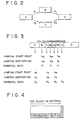
- the scheduler 30 sections the block B into a predetermined number of blocks B 1 to B 3 and sections the block C into a predetermined number of blocks C 1 to C 3 as shown in FIG. 3, and arranges, in the bit stream, the blocks in the order of the blocks B 1 , C 1 , B 2 , C 2 , B 3 and C 3 following the block A and arranges the block D following them.
- the bit stream when it is reproduced after it is recorded onto the optical disk 50 (optical disk 20), either it is reproduced in the order of the block A and the blocks B 1 , B 2 , B 3 and D or in the other order of the blocks A, C 1 , C 2 , C 3 and D.
- the sector addresses at start points at the boundaries between the blocks A, B 1 , C 1 , B 2 , C 2 , B 3 , C 3 and D are a s , b 1s , c 1s , b 2s , c 2s , b 3s , c 3s and d s and the sector addresses of end points at the boundaries are a e , b 1e , c 1e , b 2e , c 2e , b 3e , c 3e and d e
- jumping is performed from the address b 1e to the address b 2s and the block B 2 is reproduced.
- jumping from the address b 2e of the end point of the block B 2 to the address b 3s of the start point of the block B 3 is performed and the block B 3 is reproduced. Thereafter, jumping from the address b 3e of the end point of the block B 3 to the address d s of the start point of the block D is performed and the block D is reproduced.
- jumping from the address a e of the end point of the block A to the address c 1s of the start point of the block C 1 is performed and the block C 1 is reproduced.
- jumping from the address c 1e of the end point of the block C 1 to the address c 2s of the start point of the block C 2 is performed and the block C 2 is reproduced.
- jumping from the address c 2e of the end point of the block C2 to the address c 3s of the start point of the block C 3 is performed and reproduction is performed in order of the blocks C 3 and D.
- the parental rate P 2 is recorded, and as a sector address of a start point of jumping, a e is recorded, and then as a sector address of a destination of jumping, c 1s is recorded, all by the scheduler 30.
- the parental rate P 1 , a jumping start point address b 1e and a jumping destination address b 2s are recorded into the block B 1 ;
- the parental rate P 2 , a jumping start point address c 1e and a jumping destination address c 2s are recorded into the block C 1 ;
- the parental rate P 1 , a jumping start point address b 2e and a jumping destination address b 3s are recorded into the block B 2 ;
- the parental rate P 2 , a jumping start point address c 2e and a jumping destination address c 3s are recorded into the block C 2 ;
- the parental rate P 1 , a jumping start point address b 3e and a jumping destination address d s are recorded into the block B 3 ; and the parental rate P 2 is recorded into the block C 3 .
- the sector unit 16 sections the data inputted thereto from the scheduler 30 (data sectioned in a predetermined number of sections and arranged in a predetermined order as shown in FIG. 3) into sectors each including data of 2,048 bytes and adds a sector address to each of the sectors.
- the ECC encoder 17 forms, in response to data inputted thereto from the sector unit 16, 16 sectors of the data into one ECC block and adds parity codes for detection and correction of errors to the ECC block.
- the ECC encoder 17 adds an ECC (redundancy) section including inner codes and outer codes to the data of 16 sectors. Then, as shown in FIG. 5, data of each ECC block (data of 16 sectors indicated by the number 1 to the number 16) are outputted in order to the modulator 18.
- ECC redundancy
- the modulator 18 modulates the data inputted thereto and outputs the modulated data to the cutting machine 19.
- the cutting machine 19 cuts the optical disk 20 in response to the data inputted thereto.
- the optical disk 20 is developed, and a stamper is produced using the optical disk 20 as an original disk. Then, a large number of replica disks which may be used for the optical disk 50 are produced from the stamper.
- the length of the block B 1 is determined. As seen in FIG. 9, the block B 1 is skipped after the block A is reproduced. If skipping is performed, then the data can not be reproduced during the skipping. Accordingly, during the skipping, data stored in the ring buffer memory 57 (jump buffer memory 91) are read out. However, in order to prevent missing of data during the skipping, the length of the block B 1 must be set to a length with which the skipping is completed before the stored data of the jump buffer memory 91 are used up. Therefore, the maximum length of the block B 1 for preventing the ring buffer memory 57 from becoming empty is calculated first.
- the ring buffer memory 57 of the optical disk apparatus which will be hereinafter described in detail with reference to FIG. 14 includes, as shown in FIG. 15, a jump buffer memory 91 and a latency buffer memory 92.
- the jump buffer memory 91 is provided to prevent interruption of data even when sectioned data are skipped as described hereinabove with reference to FIG. 3.
- the latency buffer memory 92 has a capacity for a maximum one track (maximum value of ⁇ x latency time). Consequently, even when one track jumping is performed in the optical disk apparatus, data are prevented from missing.
- the capacity of the jump buffer memory 91 can be calculated from the expression (1) given hereinabove. It is to be noted that ⁇ in the expression (1) above represents the output rate of a beat stream read out from the ring buffer memory 57 (latency buffer memory 92).
- the capacity of the ring buffer memory 57 and the maximum value of the latency time are stored in advance in the memory 32 as described hereinabove.
- the scheduler 30 can read out the stored values and calculate the capacity of the jump buffer memory 91 from the expression (1) given hereinabove.
- step S1 While the capacity of the jump buffer memory is calculated from the expression (1) above in step S1, where the capacity of the jump buffer memory is defined in advance, this may alternatively be stored in the memory 32 and read out from it.
- the block B 1 is skipped immediately after the block A is reproduced. Since the block A has a sufficiently large length, it can be considered that the jump buffer memory 91 immediately after the block A is reproduced has data stored fully therein.
- the time (compensation time) in which the fully stored data are used up can be calculated from the expression (2) above.
- step S3 a maximum time which can be used to skip the block B 1 (to perform jumping from the block A to the block C 1 ) is calculated from the following expression (3):
- T ECC represents a time required to process an ECC block (more accurately, a time required to perform processing for 15 sectors as hereinafter described), and Ts represents a time required to reproduce data for one sector.
- error correction is performed in units of an ECC block formed from 16 sectors.
- the last sector of the block A is a sector of the number 1 from within the 16 sectors of the number 1 to the number 16 of the ECC block as shown in FIG. 10
- the data of the other 15 sectors of the ECC block of the number 2 to the number 16 following the sector of the number 1. Accordingly, jumping cannot be performed until after the data of the following 15 sectors are fetched.
- step S4 in which the maximum time which can be used for skipping of the section B 1 calculated in step S3 is converted into a corresponding distance (sector number). This conversion can be performed from a minimum jumping speed determined as a standard for the pickup of the optical disk apparatus.
- a sector number corresponding to the maximum skipping time for the section B 1 can be calculated.
- the relationship between the time t required for jumping and the sector number exhibits such a stepwise variation as shown in FIG. 11.
- the corresponding sector number is a sector number N 2 which can be skipped in a time t 12 shorter than the time t 21 .
- a maximum length is calculated which can be used as a length of the section B 1 from the point of view of preventing the data having been stored immediately prior to jumping into the jump buffer memory 91 from being used up.
- the jump buffer memory 91 is full of the data of the section B 1 when jumping is to be performed (because the skipping time for the section C 1 can be set longer as much).
- the length of the section B 1 necessary to make the jump buffer memory 91 full is calculated subsequently.
- the time T 1 in which the jump buffer memory 91 becomes full can be calculated from the expression (4) above.
- the length calculated in steps S5 and S6 is a maximum value not only for the section B 1 but common to the sections and is used also to determine the length of any section other than the section B 1 .
- a length required to store data by a predetermined amount (for example, by an amount equal to 90 % the full amount) into the jump buffer memory 91 may be calculated in steps S5 and S6.
- step S7 a smaller one of the maximum length of the section B 1 required to prevent the jump buffer memory 91 calculated in step S4 from becoming empty and the length of the section B 1 calculated in step S6 for making the jump buffer memory 91 full is selected and the selected length is finally determined as the length of the section B 1 .
- step S12 in which the sector number corresponding to the maximum skipping time for the section C 1 calculated in step S11 is calculated.
- the maximum length of the section C 2 for preventing the jump buffer memory 91 from becoming empty can be calculated.
- step S13 the maximum length of the section C 1 calculated in step S12 and the maximum length of the section C 1 (common to the sections) calculated in step S6 are compared with each other and a smaller one of the lengths is finally determined as the length of the section C 1 .
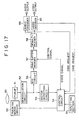
- FIG. 14 shows an optical disk apparatus which reproduces the optical disk 50 formed in such a manner as described above.
- the optical disk apparatus includes all of the components of the optical disk apparatus described hereinabove with reference to FIG. 17. Overlapping description of the common components is omitted here to avoid redundancy.
- an output of the ECC circuit 56 is inputted to a control information extractor 70.
- the control information extractor 70 extracts control information (jump information and parental rate information) described hereinabove with reference to FIG. 3 from the data inputted thereto and outputs the extracted control information to the control circuit 54 which serves as control means.
- the control information extractor 70 outputs data of the information inputted thereto from the ECC circuit 56 except the control information to the ring buffer memory 57 so that the data may be stored into the ring buffer memory 57.
- the ring buffer memory 57 is formed from, as shown in FIG. 15, a jump buffer memory 91 serving as storage means and a latency buffer memory 92 serving as the storage means.
- the pickup 51 serving as reproduction means irradiates a laser beam upon the optical disk 50 and reproduces data recorded on the optical disk 50 from reflected light of the laser beam from the optical disk 50.
- a reproduction signal outputted from the pickup 51 is inputted to and demodulated by the demodulation circuit 52.
- the data demodulated by the demodulation circuit 52 are inputted to the sector detection circuit 53, by which a sector address is detected.
- the control circuit 54 discriminates a current position of the pickup 51 from the sector address supplied thereto from the sector detection circuit 53. If the current position is not a desired position, the control circuit 54 controls the tracking servo circuit 55 to feed the pickup 51 to a predetermined sector address position. Consequently, data recorded at the predetermined position of the optical disk 50 are reproduced by the pickup 51.
- the data outputted from the demodulation circuit 52 are inputted to the ECC circuit 56, by which detection and correction of errors of them are performed, whereafter they are inputted to and stored into the ring buffer memory 57.
- the data stored in the ring buffer memory 57 are read out again from the ring buffer memory 57 and inputted to the demultiplexer 58.
- the demultiplexer 58 demultiplexes the data inputted thereto into audio data and video data, and outputs the audio data to the audio decoder 59 and outputs the video data to the video decoder 60.
- the audio decoder 59 decodes the audio data inputted thereto and outputs the decoded audio data to the loudspeaker not shown.
- the video decoder 60 decodes the video data inputted thereto and outputs the decoded video data to the monitor apparatus not shown.
- Each of the audio decoder 59 and the video decoder 60 outputs a code request signal to the control circuit 54 when its decoding processing is completed.
- the control circuit 54 controls the latency buffer memory 92 in response to the code request signals to read out data stored in the latency buffer memory 92 and output the thus read out data to the audio decoder 59 and the video decoder 60 via the demultiplexer 58.
- the control circuit 54 monitors the state signal inputted thereto from the latency buffer memory 92 and controls the position of the pickup 51 via the tracking servo circuit 55 so that the latency buffer memory 92 may not overflow or underflow.
- the input rate of data to the latency buffer memory 92 is set so as to have a value sufficiently higher than the output rate.
- the latency buffer memory 92 has a capacity at least corresponding to a maximum latency time of the optical disk 50 (where the optical disk 50 is a CLV disk, a capacity for one rotation on an outermost circumference) so that data of a variable rate inputted to the latency buffer memory 92 may be outputted continuously at a predetermined output rate.
- the tracking servo circuit 55 causes the reproduction position by the pickup 51 to a position on the inner circumference side by one track distance. Then, the control circuit 54 inhibits writing of new data into the ring buffer memory 57 (latency buffer memory 92) for a time until the optical disk 50 makes one rotation again so that the reproduction position returns to the position prior to the jumping, that is, for a time until the sector number obtained from the sector detection circuit 53 returns to the number of the sector from which the track jumping has been performed. Then, data stored already in the latency buffer memory 92 are transferred to the audio decoder 59 and the video decoder 60 via the demultiplexer 58 in accordance with the necessity.
- the average transfer rate ⁇ to the latency buffer memory 92 fluctuates at values lower than the maximum average transfer rate ⁇ m.
- the latency buffer memory 92 at least has a capacity with which it can store data at least for one track (one rotation) of the optical disk 50, that is, a storage capacity of (maximum rotation period of optical disk 50) x ⁇ m. Consequently, where the optical disk 50 is, for example, a CLV disk, since the period of rotation exhibits a maximum value at an outermost circumference thereof, the latency buffer memory 92 at least has a storage capacity for one track (one rotation) on the outermost circumference, that is, the storage capacity of (period of rotation of outermost circumference) x ⁇ m.
- ⁇ m is set to a value equal to or lower than ⁇ m ( ⁇ m ⁇ ⁇ m).
- ⁇ m is set to a value equal to or lower than ⁇ m ( ⁇ m ⁇ ⁇ m).
- ⁇ m is considerably lower than ⁇ m, for example, equal to approximately one half the value ⁇ m
- the amount of data reproduced when the optical disk 50 makes one rotation is considerably different between an inner circumference and an outer circumference thereof. If the storage amount of the latency buffer memory 92 is adjusted to an outermost circumference of the optical disk 50 with which the data amount is largest as described above, then the storage capacity of the latency buffer memory 92 has a considerable room at an inner circumference of the optical disk 50. Accordingly, when an uncorrectable error is detected by the ECC circuit 56, the possibility in which recovery against the error can be performed is increased by performing jumping back to fetch the same data again and performing error detection and correction processing again.
- the latency buffer memory 92 has the same function as that of a ring buffer memory proposed by the present applicant in Japanese Patent Laid-Open No. Hei 4-92223.
- control information extractor 70 extracts control information from information outputted from the ECC circuit 56 and outputs the control information to the control circuit 54.
- the control circuit 54 controls, if the sector address inputted from the sector detection circuit 53 (the address of a sector being accessed at present by the pickup 51) becomes coincident with the sector address of the jumping start point extracted by the control information extractor 70, the pickup 51 via the tracking servo circuit 55 to cause the pickup 51 to jump to the sector address of the jumping destination defined in the control information extracted by the control information extractor 70.
- the control circuit 54 automatically selects a reproduction order corresponding to the input. For example, if the parental rate inputted from and set by the inputting section 61 is P 1 as shown in FIG. 3, the block A, then the block B 1 , the block B 2 , the block B 3 and the block D are successively reproduced in response to addresses of jumping start points and jumping destinations set corresponding to the parental rate. On the other hand, if the parental rate inputted from the inputting section 61 is P 2 , then reproduction is performed in the order of the block A, the block C 1 , the block C 2 , the block C 3 and the block D.
Landscapes
- Engineering & Computer Science (AREA)
- Signal Processing (AREA)
- Multimedia (AREA)
- Computer Security & Cryptography (AREA)
- Signal Processing For Digital Recording And Reproducing (AREA)
- Holo Graphy (AREA)
- Television Signal Processing For Recording (AREA)
- Optical Recording Or Reproduction (AREA)
Abstract
Description
- This invention relates to data recording and reproduction.
- An encoder as a recording data production apparatus which produces data to be recorded onto a recording medium typically has such a construction as shown in FIG. 16. Referring to FIG. 16, a
storage apparatus 10 stores video data to be recorded onto a recording medium such as anoptical disk 20. The video data are read out from thestorage apparatus 10 and inputted to avideo encoder 11, by which the video data are encoded in accordance with the MPEG2 video standards. Meanwhile, audio data to be recorded onto a recording medium are stored in anotherstorage apparatus 13. The audio data are read out from thestorage apparatus 13 and supplied to anaudio encoder 14, by which the audio data are encoded in accordance with the MPEG audio standards. Amultiplexer 12 multiplexes the video data inputted thereto from thevideo encoder 11 and the audio data inputted thereto from theaudio encoder 14 and outputs the multiplexed data. - A
sector unit 16 divides the multiplexed data inputted thereto from themultiplexer 12 in units of data of 2,048 bytes into sectors, adds sector addresses to the sectors and outputs the sectors to anECC encoder 17. TheECC encoder 17 collects the data in units of a sector supplied thereto from thesector unit 16 for 16 sectors to form an ECC block, adds redundancy data (ECC) for error correction to the ECC block and outputs the ECC block to amodulator 18. Themodulator 18 modulates the data inputted thereto from theECC encoder 17 and outputs them to acutting machine 19. Thecutting machine 19 cuts anoptical disk 20 in accordance with the data inputted thereto. - In operation, video data stored in advance in the
storage apparatus 10 are inputted to thevideo encoder 11, by which they are encoded in accordance with the MPEG2 video standards. In particular, the video data undergo DCT (discrete cosine transform) processing, quantization processing, VLC (variable length coding) processing and other necessary processing and are then outputted to themultiplexer 12. Meanwhile, audio data stored in advance in thestorage apparatus 13 are inputted to theaudio encoder 14, by which they are encoded in accordance with the MPEG audio standards. In particular, the audio data undergo DCT processing, quantization processing, VLC processing and other necessary processing and are then inputted to themultiplexer 12. Themultiplexer 12 time division multiplexes the video data inputted thereto from thevideo encoder 11 and the audio data inputted thereto from theaudio encoder 14 in accordance with the MPEG2 system standards to produce data in the form of a multiplexed stream. - The data outputted from the
multiplexer 12 are inputted to thesector unit 16, by which they are divided into sectors each including data of 2,048 bytes and a sector address is added to each of the sectors. The resulting sectors are inputted to theECC encoder 17. TheECC encoder 17 adds redundancy data for error correction to the data inputted thereto and outputs resulting data to themodulator 18. Themodulator 18 modulates the data inputted thereto from theECC encoder 17 and supplies the modulated data to thecutting machine 19. - The
cutting machine 19 modulates light to be irradiated upon theoptical disk 20 in accordance with the data inputted thereto from themodulator 18 to record the data onto theoptical disk 20. - Then, the
optical disk 20 is developed, and a stamper is produced using theoptical disk 20 as an original disk. Then, a large number of replica disks are produced from the stamper. - FIG. 17 shows a typical construction of an optical disk apparatus for reproducing a replica disk produced in this manner. Referring to FIG. 17, a
pickup 51 irradiates a laser beam upon an optical disk (replica disk) 50 and reproduces data recorded on theoptical disk 50 from reflected light from theoptical disk 50. Consequently, a reproduction signal in the form of a radio frequency (RF) signal is outputted from thepickup 51 and inputted to ademodulation circuit 52, by which it is demodulated. Thedemodulation circuit 52 outputs a demodulation output to asector detection circuit 53 and anECC circuit 56. - The
sector detection circuit 53 detects a sector address from within the demodulation output inputted thereto from thedemodulation circuit 52 and outputs the detected sector address to acontrol circuit 54 which may be formed from a microcomputer or a like element. Thecontrol circuit 54 receives a state signal designating a stored amount from aring buffer memory 57. Thecontrol circuit 54 suitably controls atracking servo circuit 55 in response to an output of thesector detection circuit 53 and an output of thering buffer memory 57 so that thepickup 51 may be fed to a predetermined track position of theoptical disk 50. Aninputting section 61 is manually operated in order to input a predetermined instruction to thecontrol circuit 54. - The
ECC circuit 56 effects error correction processing of the demodulation output inputted thereto from thedemodulation circuit 52 and outputs resulting data to thering buffer memory 57. Thering buffer memory 57 temporarily stores the data inputted thereto from theECC circuit 56 and outputs a state signal designating a stored amount of the data therein to thecontrol circuit 54. - A
demultiplexer 58 demultiplexes data read out from thering buffer memory 57 in accordance with the MPEG system standards and outputs audio data to anaudio decoder 59 while it outputs video data to avideo decoder 60. Theaudio decoder 59 decodes (that is, performs inverse VLC processing, dequantization processing, inverse DCT processing and so forth of) the audio data inputted thereto in accordance with the MPEG audio standards and outputs resulting data to a loudspeaker or the like not shown. Meanwhile, thevideo decoder 60 decodes (that is, performs inverse VLC processing, dequantization processing, inverse DCT processing and so forth of) the video data inputted thereto in accordance with the MPEG2 video standards and outputs resulting data to a monitor apparatus not shown. - In operation, the
pickup 51 irradiates a laser beam upon theoptical disk 50 and reproduces data recorded on theoptical disk 50 from reflected light of the laser beam from theoptical disk 50. A reproduction signal outputted from thepickup 51 is inputted to thedemodulation circuit 52, by which it is demodulated. The data demodulated by thedemodulation circuit 52 are inputted to thesector detection circuit 53, by which a sector address is detected. Thecontrol circuit 54 discriminates a current position of thepickup 51 from the sector address supplied thereto from thesector detection circuit 53 and controls, when the current position is not a desired position, thetracking servo circuit 55 so that thepickup 51 is fed to a predetermined sector address position. Consequently, the data recorded at the predetermined position of theoptical disk 50 are reproduced by thepickup 51. - The data outputted from the
demodulation circuit 52 are inputted to theECC circuit 56, by which detection and correction of errors of them are performed, and resulting data from theECC circuit 56 are inputted to and stored into thering buffer memory 57. The data stored in thering buffer memory 57 are read out therefrom and inputted to thedemultiplexer 58. Thedemultiplexer 58 demultiplexes the data inputted thereto into audio data and video data, and outputs the audio data to theaudio decoder 59 and outputs the video data to thevideo decoder 60. Theaudio decoder 59 decodes the audio data inputted thereto and outputs resulting data to the loudspeaker not shown. Meanwhile, thevideo decoder 60 decodes the video data inputted thereto and outputs resulting data to the monitor apparatus not shown. - Each of the
audio decoder 59 and thevideo decoder 60 outputs a code request signal to thecontrol circuit 54 when decoding processing thereof is completed. Thecontrol circuit 54 controls thering buffer memory 57 in response to the code request signals to read out data stored in thering buffer memory 57 and output the thus read out data to theaudio decoder 59 and thevideo decoder 60 via thedemultiplexer 58. - The
control circuit 54 monitors a state signal inputted thereto from thering buffer memory 57 and controls the position of thepickup 51 via thetracking servo circuit 55 so that thering buffer memory 57 may not overflow or underflow. - The input rate of data to the
ring buffer memory 57 is set so that it has a value sufficiently higher than the output rate from thering buffer memory 57. Thering buffer memory 57 has a capacity at least corresponding to a maximum latency time of the optical disk 50 (where theoptical disk 50 is a constant linear velocity (CLV) disk, a capacity for one circumference on the outermost circumference) so that data of a variable rate inputted to thering buffer memory 57 can be outputted continuously at a predetermined output rate. - Video data and audio data can be recorded and reproduced digitally onto and from the
optical disk 50 in such a manner as described above. - With the system described above, however, data recorded on the
optical disk 50 are successively reproduced in order, and there is a subject to be solved in that, in order to reproduce the data recorded on theoptical disk 50 in a different order from the order in which the data are recorded on theoptical disk 50, theinputting section 61 must be manually operated to designate an order of reproduction every time into thecontrol circuit 54 of the optical disk apparatus. - Where video data are recorded, for example, as seen in FIG. 18, in the order of blocks A, B, C and D, it is sometimes desired to reproduce the block D skipping the block C after the block A and the block B are reproduced (reproduction order 1) or to successively reproduce the block C and the block D skipping the block B after the block A is reproduced (reproduction order 2).
- It is assumed that, for example, images of the video data recorded in the block C include some image which is not very preferable to viewers of a predetermined age group. In such an instance, for viewers of the age group, it is preferable to effect reproduction in the
reproduction order 1 so that images of the block C may not be reproduced. - Similarly, in such a case wherein it is not preferable to viewers of another age group to allow them to enjoy images of the block B, reproduction must be performed in the
reproduction order 2 skipping the block B. Where theoptical disk 50 is a digital video disk, a parental rate (ages for which enjoyment is permitted (inhibited)) can be recorded so that predetermined images may not be enjoyed by viewers of a predetermined age group in this manner. In particular, when the digital video disk is to be reproduced, if a viewer manually operates theinputting section 61 to input the age of the viewer itself, the system can inhibit reproduction of images which are not preferable to the age group of the age. - However,with the system, while a parental rate which represents that it is not preferable, for example, for the block C or B to be enjoyed by viewers of a predetermined age group can be recorded, since the length of the block C or B is an arbitrary length, if reproduction is performed skipping the block C or the block B as seen in FIG. 18, then the
ring buffer memory 57 will underflow. Consequently, data are not temporarily supplied to theaudio decoder 59 or thevideo decoder 60, and such a situation that some images are missed possibly occurs. - Various respective aspects of the invention are defined in the appended claims.
- Embodiments of the present invention can provide a recording data production apparatus and method, a recording medium reproduction apparatus and method and a recording medium by which interruption of data can be prevented even when reproduction of data is performed in a different order from the order in which the data are recorded.
- This invention provides a recording data production apparatus for producing data to be recorded onto a recording medium to be reproduced by a reproduction apparatus, comprising storage means for storing a capacity of a buffer memory of the reproduction apparatus for storing the data, input/output rates to and from the buffer memory, a speed in track jumping of a pickup of the reproduction apparatus when the data are reproduced from the recording medium, a latency time of the recording medium and a processing time relation information of an ECC, and sectioning means for sectioning the data in response to the storage of the storage means so that the reproduction apparatus may reproduce the data in an order different from an order in which the data are recorded on the recording medium.
- According to another aspect of the present invention, there is provided a recording data production method for producing data to be recorded onto a recording medium to be reproduced by a reproduction apparatus, comprising the steps of storing in advance a capacity of a buffer memory of the reproduction apparatus for storing the data, input/output rates to and from the buffer memory, a speed in track jumping of a pickup of the reproduction apparatus when the data are reproduced from the recording medium, a latency time of the recording medium and a processing time relation information of an ECC, and sectioning the data in response to the stored information so that the reproduction apparatus may reproduce the data in an order different from an order in which the data are recorded on the recording medium.
- In embodiments of the recording data production apparatus and the recording data production method, data are sectioned in response to stored information such as the capacity of the buffer memory of the reproduction apparatus for storing data, the input/output rates to and from the buffer memory, the speed in track jumping of the pickup when the data are reproduced from a recording medium, the latency time of the recording medium and the processing time relation information of the ECC. Consequently, the data can be reproduced in an order different from an order in which the data are recorded on the recording medium without suffering from interruption.
- According to a further aspect of the present invention, there is provided a recording data production apparatus which sections data into a plurality of sections and produces data to be recorded onto a recording medium to be reproduced by a reproduction apparatus so that the data of the sections may be reproduced by the reproduction apparatus in an order different from an order in which the data are recorded on the recording medium, comprising first calculation means for calculating a length of the sections necessary to prevent a buffer memory of the reproduction apparatus for storing the data from becoming empty within an interval within which a reproduction point is jumped to a next section, second calculation means for calculating a length of the sections necessary for data reproduced from the recording medium to be stored by a predetermined amount into the buffer memory, and determination means for determining a length of the sections from a result of the calculation of the first calculation means and a result of the calculation of the second calculation means.
- According to a still further aspect of the present invention, there is provided a recording data production method wherein data are sectioned into a plurality of sections and data to be recorded onto a recording medium to be reproduced by a reproduction apparatus so that the data of the sections may be reproduced by the reproduction apparatus in an order different from an order in which the data are recorded on the recording medium are produced, comprising the steps of calculating a length of the sections necessary to prevent a buffer memory of the reproduction apparatus for storing the data from becoming empty within an interval within which a reproduction point is jumped to a next section, calculating a length of the sections necessary for data reproduced from the recording medium to be stored by a predetermined amount into the buffer memory, and determining a length of the sections from results of the two calculations.
- In embodiments of the recording data production apparatus and the recording data production method, a length of sections for prevention of the capacity of the buffer memory from becoming empty is calculated and another length of the sections is calculated from the capacity by which data are stored by a predetermined amount into the buffer memory, and then the length of the sections is determined from results of the two calculations. Consequently, the length of the sections can be determined rapidly with certainty.
- According to a yet further aspect of the present invention, there is provided recording medium, having recorded thereon data which are sectioned in a plurality of sections such that the data of the sections can be reproduced by a reproduction apparatus in an order different from an order in which the data are recorded on the recording medium, the sections having a length determined corresponding to one of a value required to prevent a buffer memory of the reproduction apparatus for storing the data from becoming empty within an interval within which a reproduction point is jumped to a next section and another value necessary for data reproduced from the recording medium to be stored by a predetermined amount into the buffer memory.
- In embodiments of the recording medium, data are recorded thereon with a length of sections which is determined in response to one of a value calculated in order to prevent the buffer memory from becoming empty and another value calculated from a capacity which allows data to be stored by a predetermined amount into the buffer memory. Consequently, even where the order of reproduction is different from that in which the sections are recorded thereon, the recording medium assures prevention of otherwise possible missing of data upon reproduction.
- According to a yet further aspect of the present invention, there is provided a recording medium reproduction apparatus for reproducing a recording medium on which data sectioned in a plurality of sections are recorded such that the data of the sections can be reproduced in an order different from an order in which the data are recorded on the recording medium, comprising reproduction means for reproducing the data recorded on the recording medium, storage means for storing the data reproduced by the reproduction means, and control means for controlling the reproduction means so that the reproduction means jumps to a position corresponding to a value necessary to prevent the storage means from becoming empty within a period within which the reproduction means jumps to a next section or to another position corresponding to a value necessary for data reproduced from the recording medium to be stored by a predetermined amount into the storage means.
- According to a yet further aspect of the present invention, there is provided a recording medium reproduction method for reproducing a recording medium on which data sectioned in a plurality of sections are recorded such that the data of the sections can be reproduced in an order different from an order in which the data are recorded on the recording medium, comprising the steps of reproducing the data recorded on the recording medium by means of a pickup, storing the reproduced data into a buffer memory, and causing the pickup to jump to a position corresponding to a value necessary to prevent the buffer memory from becoming empty within a period within which the pickup jumps to a next section or to another position corresponding to a value necessary for data reproduced from the recording medium to be stored by a predetermined amount into the buffer memory.
- In embodiments of the recording medium reproduction apparatus and the recording medium reproduction method, jumping is performed to a position corresponding to a value calculated in order to prevent the storage means or buffer memory from becoming empty or another position corresponding to another value calculated from a capacity which allows data to be stored by a predetermined amount into the storage means or buffer memory. Consequently, the data recorded on the recording medium can be reproduced in an order different from the order in which the data are recorded on the recording medium without suffering from interruption.
- According to a yet further aspect of the present invention, there is provided a recording medium reproduction apparatus for reproducing a recording medium on which data sectioned in a plurality of sections are recorded such that the data of the sections can be reproduced in an order different from an order in which the data are recorded on the recording medium, comprising reproduction means for reproducing the data recorded on the recording medium, storage means for storing the data reproduced by the reproduction means and inputted thereto at an input rate and outputting the data at an output rate lower than the input rate, and control means for causing the reproduction means to jump to a predetermined position, the storage means having a capacity at least corresponding to a sum of a time required for the jumping of the reproduction means and a data waiting time corresponding to a processing unit for error correction of the data.
- According to a yet further aspect of the present invention, there is provided a recording medium reproduction method for reproducing a recording medium on which data sectioned in a plurality of sections are recorded such that the data of the sections can be reproduced in an order different from an order in which the data are recorded on the recording medium, comprising the steps of reproducing the data recorded on the recording medium by means of a pickup, storing the data reproduced from the recording medium and inputted thereto at an input rate once into a buffer memory which has a capacity at least corresponding to a sum of a time required for the jumping of the pickup and a data waiting time corresponding to a processing unit for error correction of the data, and outputting the data stored in the buffer memory at an output rate lower than the input rate.
- In embodiments of the recording medium reproduction apparatus and the recording medium reproduction method, the capacity of the storage means or buffer memory is set in response to a sum of a time required for jumping of the reproduction means or pickup and a data waiting time corresponding to a processing unit for error correction, and reproduced data are stored once into the buffer memory having the capacity thus set. Then, the stored data are outputted at the output rate lower than the input rate. Consequently, the data recorded on the recording medium can be reproduced in an order different from an order in which the data are recorded on the recording medium without suffering from interruption.
- According to a yet further aspect of the present invention, there is provided a data production apparatus for producing data to be reproduced by a reproduction apparatus, comprising first means for calculating a maximum length of data with which a buffer memory of the reproduction apparatus for temporarily storing the data reproduced by the reproduction apparatus does not become empty within a period within which no data are inputted to the buffer memory, second means for sectioning the data into a plurality of units in response to the first means, and third means for interleaving the data unit by unit and outputting the interleaved data.
- According to a yet further aspect of the present invention, there is provided a data production method for producing data to be reproduced by a reproduction apparatus, comprising the first step of calculating a maximum length of data with which a buffer memory of the reproduction apparatus for temporarily storing the data reproduced by the reproduction apparatus does not become empty within a period within which no data are inputted to the buffer memory, the second step of sectioning the data into a plurality of units in response to the calculated maximum length of data, and the third step of interleaving the data unit by unit and outputting the interleaved data.
- In embodiments of the data production apparatus and the data production method, data are sectioned into a plurality of units in response to the maximum length of data with which the buffer memory of the reproduction apparatus does not become empty within a period within which no data are inputted to the buffer memory. Then, the data are interleaved unit by unit and outputted in the interleaved condition so that they may be recorded on a recording medium. Consequently, the data can be reproduced in an order different from the order in which the data are recorded on the recording medium without suffering from interruption.
- The invention will now be described by way of example with reference to the accompanying drawings, throughout which like parts are referred to by like references, and in which:
- FIG. 1 is a block diagram of an encoder to which a recording data production apparatus according to an embodiment of the present invention is applied;
- FIG. 2 is a diagrammatic view illustrating orders in which data may be reproduced;
- FIG. 3 is a diagrammatic view illustrating a method of sectioning and recording data by the encoder of FIG. 1;
- FIG. 4 is a diagrammatic view illustrating an ECC block;
- FIG. 5 is a diagrammatic view illustrating a bit stream wherein an ECC block is used as a unit.
- FIGS. 6a, 6b, 7a, 7b and 8 are flow charts illustrating operation of a scheduler shown in FIG. 1;
- FIG. 9 is a diagrammatic view illustrating an order in which data are reproduced;
- FIG. 10 is a diagrammatic view illustrating a relationship between an ECC block and a jumping operation of the recording data production apparatus of FIG. 1;
- FIG. 11 is a diagram illustrating a relationship between a time required for jumping and a sector number;
- FIG. 12 is a diagrammatic view illustrating operation of skipping a sectioned block;
- FIG. 13 is a diagrammatic view illustrating a storage capacity of a jump buffer memory of the recording data reproduction apparatus of FIG. 1 in a jumping operation;
- FIG. 14 is a block diagram of an optical disk apparatus to which a recording medium reproduction apparatus according to the present invention is applied;
- FIG. 15 is a block diagram of a ring buffer memory shown in FIG. 14;
- FIG. 16 is a block diagram showing of a previously proposed encoder;
- FIG. 17 is a block diagram showing a previously proposed optical disk apparatus;
- FIG. 18 is a view illustrating a manner in which blocks are reproduced in a different order from the order in which they are recorded.
- FIG. 1 shows an encoder to which a recording data production apparatus according to an embodiment of the present invention is applied. Referring to FIG. 1, the encoder shown includes all of the components of the encoder described hereinabove with reference to FIG. 16. Overlapping description of the common components is omitted here to avoid redundancy. The present encoder is different from the encoder of FIG. 16 in that a multiplexed stream of video data and audio data produced by and outputted from the
multiplexer 12 is suitably stored into astorage apparatus 15. - The multiplexed stream stored in the
storage apparatus 15 is suitably read out therefrom and inputted to ascheduler 30 serving as sectioning means. Also amemory 32 serving as storage means is connected to thescheduler 30, and player information such as a capacity of aring buffer memory 57 of an optical disk apparatus which will be hereinafter described with reference to FIG. 14, a speed of apickup 51 upon track jumping, an input rate of data when data reproduced from anoptical disk 50 are inputted to thering buffer memory 57, a maximum value of a latency time of theoptical disk 50, and a reproduction time per one sector and signal processing information such as a construction of an ECC block formed by theECC encoder 17 of the encoder are stored in advance in thememory 32. Such information is read out from thememory 32 and supplied to thescheduler 30. Further, astorage apparatus 31 is connected to thescheduler 30, and instruction data which indicate a reproduction order of video data to be recorded are stored in thestorage apparatus 31. The stored information of thememory 32 and thestorage apparatus 31 is stored in advance by a person who manually operates the encoder. - The
scheduler 30 performs scheduling processing for a multiplexed stream inputted thereto from thestorage apparatus 15 in response to the stored information of thememory 32 and thestorage apparatus 31, and outputs resulting data to thesector unit 16. - In operation, video data read out from the
storage apparatus 10 are inputted to thevideo encoder 11, by which they are encoded in accordance with the MPEG2 video standards, whereafter they are inputted to themultiplexer 12. Meanwhile, audio data corresponding to the video data are read out from thestorage apparatus 13 and inputted to theaudio encoder 14, by which they are encoded in accordance with the MPEG audio standards, whereafter they are inputted to themultiplexer 12. Themultiplexer 12 time division multiplexes the video data inputted thereto from thevideo encoder 11 and the audio data inputted thereto from theaudio encoder 14 to produce data in the form of a multiplexed stream and supplies and stores the multiplexed stream to and into thestorage apparatus 15. - It is to be noted that instructions are inputted to the
video encoder 11 and theaudio encoder 14 so that the bit rate β of the multiplexed stream may be sufficiently lower than the input rate α at which data are reproduced from theoptical disk 50 of the optical disk apparatus and inputted to thering buffer memory 57. - The multiplexed stream read out from the
storage apparatus 15 is inputted to thescheduler 30. Thescheduler 30 sections the multiplexed stream inputted thereto in response to the instruction data inputted thereto from thestorage apparatus 31. Then, thescheduler 30 effects processing of determining the length of the sections in response to the information stored in thememory 32. - For example, where the instruction data inputted from the
storage apparatus 31 indicate an instruction order to reproduce, as shown in FIG. 2, the blocks in the order of the block A, the block B and the block D (where the parental rate is P1) and another instruction order to reproduce the blocks in the order of the block A, the block C and the block D (where the parental rate is P2), thescheduler 30 sections the block B into a predetermined number of blocks B1 to B3 and sections the block C into a predetermined number of blocks C1 to C3 as shown in FIG. 3, and arranges, in the bit stream, the blocks in the order of the blocks B1, C1, B2, C2, B3 and C3 following the block A and arranges the block D following them. - Thus, when the bit stream is reproduced after it is recorded onto the optical disk 50 (optical disk 20), either it is reproduced in the order of the block A and the blocks B1, B2, B3 and D or in the other order of the blocks A, C1, C2, C3 and D. In particular, where the sector addresses at start points at the boundaries between the blocks A, B1, C1, B2, C2, B3, C3 and D are as, b1s, c1s, b2s, c2s, b3s, c3s and ds and the sector addresses of end points at the boundaries are ae, b1e, c1e, b2e, c2e, b3e, c3e and de, when reproduction is to be effected in the order of the blocks A, B and D, after reproduction of the blocks A and B1 is effected, jumping is performed from the address b1e to the address b2s and the block B2 is reproduced. Then, jumping from the address b2e of the end point of the block B2 to the address b3s of the start point of the block B3 is performed and the block B3 is reproduced. Thereafter, jumping from the address b3e of the end point of the block B3 to the address ds of the start point of the block D is performed and the block D is reproduced.
- On the other hand, when reproduction is to be performed in the order of the block A, the block C and the block D, jumping from the address ae of the end point of the block A to the address c1s of the start point of the block C1 is performed and the block C1 is reproduced. Then, jumping from the address c1e of the end point of the block C1 to the address c2s of the start point of the block C2 is performed and the block C2 is reproduced. Further, jumping from the address c2e of the end point of the block C2 to the address c3s of the start point of the block C3 is performed and reproduction is performed in order of the blocks C3 and D.
- In order to make it possible for such reproduction to be performed automatically in response to a parental rate with the optical disk apparatus, as the data of the block A, for example, as control information such as entry point information, the parental rate P2 is recorded, and as a sector address of a start point of jumping, ae is recorded, and then as a sector address of a destination of jumping, c1s is recorded, all by the
scheduler 30. Thereafter, the parental rate P1, a jumping start point address b1e and a jumping destination address b2s are recorded into the block B1; the parental rate P2, a jumping start point address c1e and a jumping destination address c2s are recorded into the block C1; the parental rate P1, a jumping start point address b2e and a jumping destination address b3s are recorded into the block B2; the parental rate P2, a jumping start point address c2e and a jumping destination address c3s are recorded into the block C2; the parental rate P1, a jumping start point address b3e and a jumping destination address ds are recorded into the block B3; and the parental rate P2 is recorded into the block C3. In the optical disk apparatus, it is possible to control, based on the information, so that jumping is performed to a jumping destination address when a current address reaches a jumping start point address. - It is to be noted that a method of determining the length of sections when a data block is sectioned into a plurality of sections will be hereinafter described with reference to the flow charts of FIGS. 6 to 8.
- The
sector unit 16 sections the data inputted thereto from the scheduler 30 (data sectioned in a predetermined number of sections and arranged in a predetermined order as shown in FIG. 3) into sectors each including data of 2,048 bytes and adds a sector address to each of the sectors. TheECC encoder 17 forms, in response to data inputted thereto from thesector unit - In particular, as shown in FIG. 4, the
ECC encoder 17 adds an ECC (redundancy) section including inner codes and outer codes to the data of 16 sectors. Then, as shown in FIG. 5, data of each ECC block (data of 16 sectors indicated by thenumber 1 to the number 16) are outputted in order to themodulator 18. - The
modulator 18 modulates the data inputted thereto and outputs the modulated data to the cuttingmachine 19. The cuttingmachine 19 cuts theoptical disk 20 in response to the data inputted thereto. - Then, the
optical disk 20 is developed, and a stamper is produced using theoptical disk 20 as an original disk. Then, a large number of replica disks which may be used for theoptical disk 50 are produced from the stamper. - Subsequently, a method of determining a length of sections of data will be described with reference to the flow charts of FIGS. 6 to 8.
- First, the length of the block B1 is determined. As seen in FIG. 9, the block B1 is skipped after the block A is reproduced. If skipping is performed, then the data can not be reproduced during the skipping. Accordingly, during the skipping, data stored in the ring buffer memory 57 (jump buffer memory 91) are read out. However, in order to prevent missing of data during the skipping, the length of the block B1 must be set to a length with which the skipping is completed before the stored data of the
jump buffer memory 91 are used up. Therefore, the maximum length of the block B1 for preventing thering buffer memory 57 from becoming empty is calculated first. - To this end, in step S1, the
scheduler 30 calculates a capacity of the jump buffer memory from the following expression (1):
- In particular, in the present embodiment, the
ring buffer memory 57 of the optical disk apparatus which will be hereinafter described in detail with reference to FIG. 14 includes, as shown in FIG. 15, ajump buffer memory 91 and alatency buffer memory 92. Thejump buffer memory 91 is provided to prevent interruption of data even when sectioned data are skipped as described hereinabove with reference to FIG. 3. Meanwhile, thelatency buffer memory 92 has a capacity for a maximum one track (maximum value of β x latency time). Consequently, even when one track jumping is performed in the optical disk apparatus, data are prevented from missing. - Accordingly, the capacity of the
jump buffer memory 91 can be calculated from the expression (1) given hereinabove. It is to be noted that β in the expression (1) above represents the output rate of a beat stream read out from the ring buffer memory 57 (latency buffer memory 92). - The capacity of the
ring buffer memory 57 and the maximum value of the latency time are stored in advance in thememory 32 as described hereinabove. Thescheduler 30 can read out the stored values and calculate the capacity of thejump buffer memory 91 from the expression (1) given hereinabove. - While the capacity of the jump buffer memory is calculated from the expression (1) above in step S1, where the capacity of the jump buffer memory is defined in advance, this may alternatively be stored in the
memory 32 and read out from it. - The block B1 is skipped immediately after the block A is reproduced. Since the block A has a sufficiently large length, it can be considered that the
jump buffer memory 91 immediately after the block A is reproduced has data stored fully therein. - Thus, the control advances to step S2, in which a time (compensation time) in which the data stored fully in the
jump buffer memory 91 are read out until thejump buffer memory 91 becomes empty is calculated from the following expression (2):
- Since the block A is sufficiently long, if the data of the block A are reproduced and stored into the
jump buffer memory 91, then the data are stored into thejump buffer memory 91 until thejump buffer memory 91 becomes full. If it is assumed that the data are read out at the output rate β, then the time (compensation time) in which the fully stored data are used up can be calculated from the expression (2) above. - Then, the control advances to step S3, in which a maximum time which can be used to skip the block B1 (to perform jumping from the block A to the block C1) is calculated from the following expression (3):

- Here, TECC represents a time required to process an ECC block (more accurately, a time required to perform processing for 15 sectors as hereinafter described), and Ts represents a time required to reproduce data for one sector.
- In particular, as shown in FIG. 4, error correction is performed in units of an ECC block formed from 16 sectors. As a result, if, for example, the last sector of the block A is a sector of the
number 1 from within the 16 sectors of thenumber 1 to thenumber 16 of the ECC block as shown in FIG. 10, then in order to effect error correction of the data of the 1 sector, also the data of the other 15 sectors of the ECC block of thenumber 2 to thenumber 16 following the sector of thenumber 1. Accordingly, jumping cannot be performed until after the data of the following 15 sectors are fetched. - On the other hand, when, as shown in FIG. 10, the top sector of the sectioned block C1 of the destination of the jumping is the last sector of the
number 16 from within the sectors of thenumber 1 to thenumber 16 of the ECC block, in order to effect error correction of the sector, also the data of the 15 sectors of thenumber 1 to thenumber 15 preceding to the sector of thenumber 16 are required. Accordingly, the time which can be used for skipping of the section B1 is a value obtained by subtracting a value twice the time TECC (= 15 x Ts) required to read data for 15 sectors from the compensation time. - Thereafter, the control advances to step S4, in which the maximum time which can be used for skipping of the section B1 calculated in step S3 is converted into a corresponding distance (sector number). This conversion can be performed from a minimum jumping speed determined as a standard for the pickup of the optical disk apparatus.
- In particular, by dividing the maximum skipping time of the section B1 calculated in step S3 by the minimum jumping speed (time required to jump by one track distance) determined as a standard for the pickup of the optical disk apparatus, a sector number corresponding to the maximum skipping time for the section B1 can be calculated.
- Actually, however, since a plurality of sectors are arranged in one track (one rotation), if one track jumping is performed, then a plurality of sectors are skipped at a time.
- For example, if it is assumed that N0 sectors are provided for one rotation and a time T0 is required to effect jumping by one track distance, then the relationship between the time t required for jumping and the sector number exhibits such a stepwise variation as shown in FIG. 11. Thus, for example, where the maximum skipping time for the section B1 calculated in step S3 is t21, the corresponding sector number is a sector number N2 which can be skipped in a time t12 shorter than the time t21.
- By the processing in steps S1 to S4 (which serves as first calculation means) described above, a maximum length is calculated which can be used as a length of the section B1 from the point of view of preventing the data having been stored immediately prior to jumping into the
jump buffer memory 91 from being used up. - When the sectioned block C1 is to be skipped as seen in FIG. 12, stored data of the section B1 are read out from the
jump buffer memory 91. In order to make the length of the section C1 long, preferably thejump buffer memory 91 is full of the data of the section B1 when jumping is to be performed (because the skipping time for the section C1 can be set longer as much). Thus, the length of the section B1 necessary to make thejump buffer memory 91 full is calculated subsequently. - To this end, the control advances to step S5, in which the time T1 (= t1 - t0) in which the
jump buffer memory 91 becomes full is calculated from the following expression (4):
- In particular, since the input rate of the
jump buffer memory 91 is α and the output rate is β, the time T1 in which thejump buffer memory 91 becomes full can be calculated from the expression (4) above. - Thereafter, the control advances to step S6, in which the capacity for data (the number of sectors of the section B1) inputted to the
jump buffer memory 91 for the time T1 is calculated from the following expression (5):
- In particular, when the data of the section B1 are inputted to the
jump buffer memory 91 as seen in FIG. 13, since the input rate is α and the output rate is β, writing into thejump buffer memory 91 is performed at the rate of α - β from time t0, and the writing of the data of the section B1 is completed at time t1. Thereafter, data of the section B1 are read out at the output rate β, and thejump buffer memory 91 becomes empty at time t2. Skipping of the section C1 must be performed within a period from time t1 to time t2, and the data amount of the section B1 to assure this period is calculated from the expression (5) above. - By the processing in steps S5 and S6 (which serve as second calculation means) described above, the length of the section B1 required to make the
jump buffer memory 91 full is calculated. - It is to be noted that the length calculated in steps S5 and S6 is a maximum value not only for the section B1 but common to the sections and is used also to determine the length of any section other than the section B1.
- Further, where the length of each section need not be set very long, a length required to store data by a predetermined amount (for example, by an amount equal to 90 % the full amount) into the
jump buffer memory 91 may be calculated in steps S5 and S6. - Subsequently, the control advances to step S7, in which a smaller one of the maximum length of the section B1 required to prevent the
jump buffer memory 91 calculated in step S4 from becoming empty and the length of the section B1 calculated in step S6 for making thejump buffer memory 91 full is selected and the selected length is finally determined as the length of the section B1. Then, the control advances to step S8, in which the sector address b1e of the end point of the section B1 is calculated from the following expression (6):
- Since the length of the section B1 is determined in such a manner as described above, processing for determining the length of the section C1 is executed subsequently. First, a maximum length which will not cause missing of data when the section C1 is skipped is calculated.
- To this end, in step S9, data stored in the
jump buffer memory 91 at time t1 of FIG. 13 is calculated from the following expression (7):
- Then, in step S10, T2 (= t2 - t1) is calculated from the stored data calculated in step S9 based on the following expression (8):

- Subsequently, the control advances to step S11, in which the time which can be used for skipping of the section C1 (jumping from the section B1 to the section B2) is calculated based on the following expression (9):

- Further, the control advances to step S12, in which the sector number corresponding to the maximum skipping time for the section C1 calculated in step S11 is calculated.
- By the processing in steps S9 to S12 above, the maximum length of the section C2 for preventing the
jump buffer memory 91 from becoming empty can be calculated. - As described hereinabove, the maximum value of the length of a section defined from the data amount for making the
jump buffer memory 91 full has been calculated already in steps S5 and S6. Therefore, the control subsequently advances to step S13, in which the maximum length of the section C1 calculated in step S12 and the maximum length of the section C1 (common to the sections) calculated in step S6 are compared with each other and a smaller one of the lengths is finally determined as the length of the section C1. - Further, in step S14, the sector address C1e of the end point of the section C is calculated from the following expression (10):

- Thereafter, the lengths of the sections from the section B2 to the section C3 are calculated in a similar manner. Description of the calculation is omitted here to avoid redundancy.
- FIG. 14 shows an optical disk apparatus which reproduces the
optical disk 50 formed in such a manner as described above. Referring to FIG. 14, the optical disk apparatus includes all of the components of the optical disk apparatus described hereinabove with reference to FIG. 17. Overlapping description of the common components is omitted here to avoid redundancy. - In the present optical disk apparatus, an output of the
ECC circuit 56 is inputted to acontrol information extractor 70. Thecontrol information extractor 70 extracts control information (jump information and parental rate information) described hereinabove with reference to FIG. 3 from the data inputted thereto and outputs the extracted control information to thecontrol circuit 54 which serves as control means. Thecontrol information extractor 70 outputs data of the information inputted thereto from theECC circuit 56 except the control information to thering buffer memory 57 so that the data may be stored into thering buffer memory 57. Thering buffer memory 57 is formed from, as shown in FIG. 15, ajump buffer memory 91 serving as storage means and alatency buffer memory 92 serving as the storage means. - The
jump buffer memory 91 has a capacity represented by the following expression (11) where the jumping time of thepickup 51 is Tj:
- Meanwhile, the
latency buffer memory 92 is set to a capacity represented by the following expression (12):
- In operation, the
pickup 51 serving as reproduction means irradiates a laser beam upon theoptical disk 50 and reproduces data recorded on theoptical disk 50 from reflected light of the laser beam from theoptical disk 50. A reproduction signal outputted from thepickup 51 is inputted to and demodulated by thedemodulation circuit 52. The data demodulated by thedemodulation circuit 52 are inputted to thesector detection circuit 53, by which a sector address is detected. Meanwhile, thecontrol circuit 54 discriminates a current position of thepickup 51 from the sector address supplied thereto from thesector detection circuit 53. If the current position is not a desired position, thecontrol circuit 54 controls the trackingservo circuit 55 to feed thepickup 51 to a predetermined sector address position. Consequently, data recorded at the predetermined position of theoptical disk 50 are reproduced by thepickup 51. - The data outputted from the
demodulation circuit 52 are inputted to theECC circuit 56, by which detection and correction of errors of them are performed, whereafter they are inputted to and stored into thering buffer memory 57. The data stored in thering buffer memory 57 are read out again from thering buffer memory 57 and inputted to thedemultiplexer 58. Thedemultiplexer 58 demultiplexes the data inputted thereto into audio data and video data, and outputs the audio data to theaudio decoder 59 and outputs the video data to thevideo decoder 60. Theaudio decoder 59 decodes the audio data inputted thereto and outputs the decoded audio data to the loudspeaker not shown. Meanwhile, thevideo decoder 60 decodes the video data inputted thereto and outputs the decoded video data to the monitor apparatus not shown. - Each of the
audio decoder 59 and thevideo decoder 60 outputs a code request signal to thecontrol circuit 54 when its decoding processing is completed. Thecontrol circuit 54 controls thelatency buffer memory 92 in response to the code request signals to read out data stored in thelatency buffer memory 92 and output the thus read out data to theaudio decoder 59 and thevideo decoder 60 via thedemultiplexer 58. - The
control circuit 54 monitors the state signal inputted thereto from thelatency buffer memory 92 and controls the position of thepickup 51 via thetracking servo circuit 55 so that thelatency buffer memory 92 may not overflow or underflow. - The input rate of data to the
latency buffer memory 92 is set so as to have a value sufficiently higher than the output rate. Thelatency buffer memory 92 has a capacity at least corresponding to a maximum latency time of the optical disk 50 (where theoptical disk 50 is a CLV disk, a capacity for one rotation on an outermost circumference) so that data of a variable rate inputted to thelatency buffer memory 92 may be outputted continuously at a predetermined output rate. - Further, operation of the
latency buffer memory 92 will be described. - If, for example, a track jumping instruction to effect jumping back is outputted from the
control circuit 54, then the trackingservo circuit 55 causes the reproduction position by thepickup 51 to a position on the inner circumference side by one track distance. Then, thecontrol circuit 54 inhibits writing of new data into the ring buffer memory 57 (latency buffer memory 92) for a time until theoptical disk 50 makes one rotation again so that the reproduction position returns to the position prior to the jumping, that is, for a time until the sector number obtained from thesector detection circuit 53 returns to the number of the sector from which the track jumping has been performed. Then, data stored already in thelatency buffer memory 92 are transferred to theaudio decoder 59 and thevideo decoder 60 via thedemultiplexer 58 in accordance with the necessity. - Further, even if the sector number obtained from the
sector detection circuit 53 after the track jumping becomes coincident with the sector number from which the track jumping has been performed, when the amount of data stored in thelatency buffer memory 92 exceeds a predetermined reference value, that is, when thelatency buffer memory 92 may possibly overflow, writing of data into thelatency buffer memory 92 is not resumed, but tracking jumping is performed again. - For a time until the
optical disk 50 makes one rotation and the original reproduction position is restored after track jumping by one track distance is performed, writing of new data into thelatency buffer memory 92 is not performed. Consequently, a time longer only by the time of the track jumping is required to effect transfer of data to thelatency buffer memory 92, and accordingly, the average transfer rate α to thelatency buffer memory 92 fluctuates at values lower than the maximum average transfer rate αm. - Here, the
latency buffer memory 92 at least has a capacity with which it can store data at least for one track (one rotation) of theoptical disk 50, that is, a storage capacity of (maximum rotation period of optical disk 50) x αm. Consequently, where theoptical disk 50 is, for example, a CLV disk, since the period of rotation exhibits a maximum value at an outermost circumference thereof, thelatency buffer memory 92 at least has a storage capacity for one track (one rotation) on the outermost circumference, that is, the storage capacity of (period of rotation of outermost circumference) x αm. - Where the maximum transfer rate from the
latency buffer memory 92 to thedemultiplexer 58 is represented by βm, βm is set to a value equal to or lower than αm (βm ≦ αm). Where the maximum transfer rate is set in this manner, a code request for data transfer from theaudio decoder 59 or thevideo decoder 60 to the latency buffer memory 92 (via the control circuit 54) can be sent out freely irrespective of the timing of track jumping. - Where βm is considerably lower than αm, for example, equal to approximately one half the value αm, since the amount of data written into the
latency buffer memory 92 is larger than the amount of data read out from thelatency buffer memory 92, a condition wherein thelatency buffer memory 92 is almost full continues. On the other hand, where theoptical disk 50 is a CLV disk, the amount of data reproduced when theoptical disk 50 makes one rotation is considerably different between an inner circumference and an outer circumference thereof. If the storage amount of thelatency buffer memory 92 is adjusted to an outermost circumference of theoptical disk 50 with which the data amount is largest as described above, then the storage capacity of thelatency buffer memory 92 has a considerable room at an inner circumference of theoptical disk 50. Accordingly, when an uncorrectable error is detected by theECC circuit 56, the possibility in which recovery against the error can be performed is increased by performing jumping back to fetch the same data again and performing error detection and correction processing again. - It is to be noted that the
latency buffer memory 92 has the same function as that of a ring buffer memory proposed by the present applicant in Japanese Patent Laid-Open No. Hei 4-92223. - Meanwhile, the
control information extractor 70 extracts control information from information outputted from theECC circuit 56 and outputs the control information to thecontrol circuit 54. When the parental rate inputted from thecontrol information extractor 70 and the parental rate of a current viewer inputted from the inputtingsection 61 are coincident with each other, thecontrol circuit 54 controls, if the sector address inputted from the sector detection circuit 53 (the address of a sector being accessed at present by the pickup 51) becomes coincident with the sector address of the jumping start point extracted by thecontrol information extractor 70, thepickup 51 via thetracking servo circuit 55 to cause thepickup 51 to jump to the sector address of the jumping destination defined in the control information extracted by thecontrol information extractor 70. - In particular, when a predetermined parental rate is inputted from the inputting
section 61, thecontrol circuit 54 automatically selects a reproduction order corresponding to the input. For example, if the parental rate inputted from and set by the inputtingsection 61 is P1 as shown in FIG. 3, the block A, then the block B1, the block B2, the block B3 and the block D are successively reproduced in response to addresses of jumping start points and jumping destinations set corresponding to the parental rate. On the other hand, if the parental rate inputted from the inputtingsection 61 is P2, then reproduction is performed in the order of the block A, the block C1, the block C2, the block C3 and the block D. - While the present invention is described above by way of an example wherein data are recorded onto and reproduced from an optical disk, the present invention can be applied to a case wherein information is recorded onto and reproduced from any other recording medium.
- Having now fully described the invention, it will be apparent to one of ordinary skill in the art that many changes and modifications can be made thereto without departing from the scope of the invention as set forth herein.
Claims (23)
- A recording data production apparatus for producing data to be recorded onto a recording medium to be reproduced by a reproduction apparatus, comprising:storage means for storing a capacity of a buffer memory of said reproduction apparatus for storing the data, input/output rates to and from said buffer memory, a speed in track jumping of a pickup of said reproduction apparatus when the data are reproduced from the recording medium, a latency time of the recording medium and a processing time relation information of an ECC; andsectioning means for sectioning the data in response to the storage of said storage means so that said reproduction apparatus may reproduce the data in an order different from an order in which the data are recorded on the recording medium.
- A recording data production method for producing data to be recorded onto a recording medium to be reproduced by a reproduction apparatus, comprising the steps of:storing in advance a capacity of a buffer memory of said reproduction apparatus for storing the data, input/output rates to and from said buffer memory, a speed in track jumping of a pickup of said reproduction apparatus when the data are reproduced from the recording medium, a latency time of the recording medium and a processing time relation information of an ECC; andsectioning the data in response to the stored information so that said reproduction apparatus may reproduce the data in an order different from an order in which the data are recorded on the recording medium.
- A recording data production apparatus which sections data into a plurality of sections and produces data to be recorded onto a recording medium to be reproduced by a reproduction apparatus so that the data of the sections may be reproduced by said reproduction apparatus in an order different from an order in which the data are recorded on the recording medium, comprising:first calculation means for calculating a length of the sections necessary to prevent a buffer memory of said reproduction apparatus for storing the data from becoming empty within an interval within which a reproduction point is jumped to a next section;second calculation means for calculating a length of the sections necessary for data reproduced from the recording medium to be stored by a predetermined amount into said buffer memory; anddetermination means for determining a length of the sections from a result of the calculation of said first calculation means and a result of the calculation of said second calculation means.
- A recording data production method wherein data are sectioned into a plurality of sections and data to be recorded onto a recording medium to be reproduced by a reproduction apparatus so that the data of the sections may be reproduced by said reproduction apparatus in an order different from an order in which the data are recorded on the recording medium are produced, comprising the steps of:calculating a length of the sections necessary to prevent a buffer memory of said reproduction apparatus for storing the data from becoming empty within an interval within which a reproduction point is jumped to a next section;calculating a length of the sections necessary for data reproduced from the recording medium to be stored by a predetermined amount into said buffer memory; anddetermining a length of the sections from results of the two calculations.
- A recording medium, having recorded thereon data which are sectioned in a plurality of sections such that the data of the sections can be reproduced by a reproduction apparatus in an order different from an order in which the data are recorded on the recording medium, the sections having a length determined corresponding to one of a value required to prevent a buffer memory of said reproduction apparatus for storing the data from becoming empty within an interval within which a reproduction point is jumped to a next section and another value necessary for data reproduced from the recording medium to be stored by a predetermined amount into said buffer memory.
- A recording medium reproduction apparatus for reproducing a recording medium on which data sectioned in a plurality of sections are recorded such that the data of the sections can be reproduced in an order different from an order in which the data are recorded on the recording medium, comprising:reproduction means for reproducing the data recorded on the recording medium;storage means for storing the data reproduced by said reproduction means; andcontrol means for controlling said reproduction means so that said reproduction means jumps to a position corresponding to a value necessary to prevent said storage means from becoming empty within a period within which said reproduction means jumps to a next section or to another position corresponding to a value necessary for data reproduced from the recording medium to be stored by a predetermined amount into said storage means.
- A recording medium reproduction method for reproducing a recording medium on which data sectioned in a plurality of sections are recorded such that the data of the sections can be reproduced in an order different from an order in which the data are recorded on the recording medium, comprising the steps of:reproducing the data recorded on the recording medium by means of a pickup;storing the reproduced data into a buffer memory; andcausing said pickup to jump to a position corresponding to a value necessary to prevent said buffer memory from becoming empty within a period within which said pickup jumps to a next section or to another position corresponding to a value necessary for data reproduced from the recording medium to be stored by a predetermined amount into said buffer memory.
- A recording medium reproduction apparatus for reproducing a recording medium on which data sectioned in a plurality of sections are recorded such that the data of the sections can be reproduced in an order different from an order in which the data are recorded on the recording medium, comprising:reproduction means for reproducing the data recorded on the recording medium;storage means for storing the data reproduced by said reproduction means and inputted thereto at an input rate and outputting the data at an output rate lower than the input rate; andcontrol means for causing said reproduction means to jump to a predetermined position;said storage means having a capacity at least corresponding to a sum of a time required for the jumping of said reproduction means and a data waiting time corresponding to a processing unit for error correction of the data.
- A recording medium reproduction apparatus according to claim 8, wherein the capacity of said storage means further corresponds to a product of a maximum value of the output rate and a maximum value of a latency time of the recording medium upon jumping.
- A recording medium reproduction method for reproducing a recording medium on which data sectioned in a plurality of sections are recorded such that the data of the sections can be reproduced in an order different from an order in which the data are recorded on the recording medium, comprising the steps of:reproducing the data recorded on the recording medium by means of a pickup;storing the data reproduced from the recording medium and inputted thereto at an input rate once into a buffer memory which has a capacity at least corresponding to a sum of a time required for the jumping of said pickup and a data waiting time corresponding to a processing unit for error correction of the data; andoutputting the data stored in said buffer memory at an output rate lower than the input rate.
- A data production apparatus for producing data to be reproduced by a reproduction apparatus, comprising:first means for calculating a maximum length of data with which a buffer memory of said reproduction apparatus for temporarily storing the data reproduced by said reproduction apparatus does not become empty within a period within which no data are inputted to said buffer memory;second means for sectioning the data into a plurality of units in response to said first means; andthird means for interleaving the data unit by unit and outputting the interleaved data.
- A data production apparatus according to claim 11, wherein said first means includes means for calculating the maximum length of data with which said buffer memory does not become empty in response to a capacity of said buffer memory and an input rate of the data to said buffer memory.
- A data production apparatus according to claim 12, wherein said first means further includes means for calculating the maximum length of data with which said buffer memory does not become empty in response to a time required for jumping of a reproduction point.
- A data production apparatus according to claim 13, wherein said first means further includes means for calculating the maximum length of data with which said buffer memory does not become empty in response to a track jumping speed of said reproduction apparatus and a latency time of a recording medium.
- A data production apparatus according to claim 13, wherein said first means further includes means for calculating the maximum length of data with which said buffer memory does not become empty in response to a time required for said reproduction apparatus to effect error correction processing of the data.
- A data production apparatus according to claim 15, wherein the data has a parity added to each data block thereof of a predetermined length.
- A data production apparatus according to claim 11, wherein said third means includes means for interleaving a plurality of image data unit by unit.
- A data production method for producing data to be reproduced by a reproduction apparatus, comprising:the first step of calculating a maximum length of data with which a buffer memory of said reproduction apparatus for temporarily storing the data reproduced by said reproduction apparatus does not become empty within a period within which no data are inputted to said buffer memory;the second step of sectioning the data into a plurality of units in response to the calculated maximum length of data; andthe third step of interleaving the data unit by unit and outputting the interleaved data.
- A data production method according to claim 18, wherein the first step includes the step of calculating the maximum length of data with which said buffer memory does not become empty in response to a capacity of said buffer memory and an input rate of the data to said buffer memory.
- A data production method according to claim 19, wherein the first step further includes the step of calculating the maximum length of data with which said buffer memory does not become empty in response to a time required for jumping of a reproduction point.
- A data production method according to claim 20, wherein the first step further includes the step of calculating the maximum length of data with which said buffer memory does not become empty in response to a track jumping speed of said reproduction apparatus and a latency time of a recording medium.
- A data production method according to claim 20, wherein the first step further includes the step of calculating the maximum length of data with which said buffer memory does not become empty in response to a time required for said reproduction apparatus to effect error correction processing of the data.
- A data production method according to claim 18, wherein the third step includes the step of interleaving a plurality of image data unit by unit.
Priority Applications (2)
| Application Number | Priority Date | Filing Date | Title |
|---|---|---|---|
| EP00203706A EP1071090B1 (en) | 1996-02-09 | 1997-01-30 | Data recording and reproduction |
| EP00203414A EP1067541B1 (en) | 1996-02-09 | 1997-01-30 | Data recording and reproduction |
Applications Claiming Priority (3)
| Application Number | Priority Date | Filing Date | Title |
|---|---|---|---|
| JP2350096 | 1996-02-09 | ||
| JP23500/96 | 1996-02-09 | ||
| JP2350096 | 1996-02-09 |
Related Child Applications (2)
| Application Number | Title | Priority Date | Filing Date |
|---|---|---|---|
| EP00203414A Division EP1067541B1 (en) | 1996-02-09 | 1997-01-30 | Data recording and reproduction |
| EP00203706A Division EP1071090B1 (en) | 1996-02-09 | 1997-01-30 | Data recording and reproduction |
Publications (3)
| Publication Number | Publication Date |
|---|---|
| EP0789360A2 true EP0789360A2 (en) | 1997-08-13 |
| EP0789360A3 EP0789360A3 (en) | 1999-06-30 |
| EP0789360B1 EP0789360B1 (en) | 2002-09-11 |
Family
ID=12112207
Family Applications (3)
| Application Number | Title | Priority Date | Filing Date |
|---|---|---|---|
| EP97300629A Expired - Lifetime EP0789360B1 (en) | 1996-02-09 | 1997-01-30 | Data recording and reproduction |
| EP00203706A Expired - Lifetime EP1071090B1 (en) | 1996-02-09 | 1997-01-30 | Data recording and reproduction |
| EP00203414A Expired - Lifetime EP1067541B1 (en) | 1996-02-09 | 1997-01-30 | Data recording and reproduction |
Family Applications After (2)
| Application Number | Title | Priority Date | Filing Date |
|---|---|---|---|
| EP00203706A Expired - Lifetime EP1071090B1 (en) | 1996-02-09 | 1997-01-30 | Data recording and reproduction |
| EP00203414A Expired - Lifetime EP1067541B1 (en) | 1996-02-09 | 1997-01-30 | Data recording and reproduction |
Country Status (10)
| Country | Link |
|---|---|
| US (2) | US5721591A (en) |
| EP (3) | EP0789360B1 (en) |
| JP (2) | JP3975471B2 (en) |
| KR (1) | KR100495713B1 (en) |
| CN (4) | CN100364003C (en) |
| AT (3) | ATE445219T1 (en) |
| DE (3) | DE69739615D1 (en) |
| HK (2) | HK1035798A1 (en) |
| MY (1) | MY115523A (en) |
| TW (1) | TW332961B (en) |
Cited By (2)
| Publication number | Priority date | Publication date | Assignee | Title |
|---|---|---|---|---|
| EP0929068A2 (en) * | 1998-01-06 | 1999-07-14 | Pioneer Electronic Corporation | Method of and apparatus for reproducing a plurality of information pieces |
| CN101128878B (en) * | 2005-02-25 | 2011-11-16 | 索尼株式会社 | Information processing device, information recording medium, information processing method, and computer program |
Families Citing this family (20)
| Publication number | Priority date | Publication date | Assignee | Title |
|---|---|---|---|---|
| US5495552A (en) * | 1992-04-20 | 1996-02-27 | Mitsubishi Denki Kabushiki Kaisha | Methods of efficiently recording an audio signal in semiconductor memory |
| TW332961B (en) * | 1996-02-09 | 1998-06-01 | Sony Co Ltd | Recording media |
| US6212208B1 (en) * | 1996-11-11 | 2001-04-03 | Matsushita Electric Industrial Co., Ltd. | Method for coding and multiplexing multimedia data, apparatus for coding and multiplexing multimedia data, record media containing program for coding and multiplexing multimedia data |
| US6286061B1 (en) * | 1998-06-02 | 2001-09-04 | Philips Electronics North America Corporation | System for applying a tag to a frame based on certain characteristics of the frame and transferring the frame as a function of the tag |
| KR100604029B1 (en) * | 1999-12-22 | 2006-07-24 | 엘지전자 주식회사 | Method for writing data in an optical disk reader/writer |
| JP2002007073A (en) * | 2000-06-22 | 2002-01-11 | Pioneer Electronic Corp | Device and method for outputting information, device and method for recording information, information output recording system and information recording medium |
| US7369665B1 (en) | 2000-08-23 | 2008-05-06 | Nintendo Co., Ltd. | Method and apparatus for mixing sound signals |
| US6643744B1 (en) | 2000-08-23 | 2003-11-04 | Nintendo Co., Ltd. | Method and apparatus for pre-fetching audio data |
| DE10163152A1 (en) * | 2001-12-20 | 2003-07-03 | Thomson Brandt Gmbh | MPEG video recording medium and playback device |
| JP3939198B2 (en) * | 2002-05-20 | 2007-07-04 | 三洋電機株式会社 | Data output device |
| JP3783233B2 (en) * | 2002-12-18 | 2006-06-07 | ソニー株式会社 | Information processing apparatus, information processing method, and program |
| US7627230B2 (en) * | 2003-03-31 | 2009-12-01 | Samsung Electronics Co., Ltd. | Information storage medium containing enhanced AV (ENAV) buffer configuration information, reproducing method thereof and method for managing the buffer |
| KR100608051B1 (en) * | 2003-07-07 | 2006-08-02 | 삼성전자주식회사 | Information storage medium for multi angle data, and recording method and reproducing apparatus thereof |
| NZ545659A (en) * | 2003-09-04 | 2008-05-30 | Koninkl Philips Electronics Nv | Record carrier carrying a video signal and at least one additional information signal |
| CN100377249C (en) * | 2004-01-08 | 2008-03-26 | 财团法人工业技术研究院 | Optical disk recording device and its control method |
| CN101714385B (en) | 2004-05-11 | 2012-09-26 | 松下电器产业株式会社 | Reproducer, program, and reproducing method |
| CN100433166C (en) * | 2006-01-27 | 2008-11-12 | 肖辉 | MP3 file generating method and playing method for generated MP3 file |
| EP2209120A4 (en) * | 2007-11-09 | 2016-12-07 | Mitsubishi Electric Corp | Video information recording method and video information reproducing device |
| US9883156B2 (en) | 2011-11-30 | 2018-01-30 | Intel Corporation | Techniques to display multimedia data during operating system initialization |
| CN114584840B (en) * | 2022-02-28 | 2024-02-23 | 北京梧桐车联科技有限责任公司 | Audio and video playing method and device and storage medium |
Citations (7)
| Publication number | Priority date | Publication date | Assignee | Title |
|---|---|---|---|---|
| JPS626469A (en) * | 1985-07-02 | 1987-01-13 | Matsushita Electric Ind Co Ltd | Interpolating device for error correction |
| EP0522853A2 (en) * | 1991-07-12 | 1993-01-13 | Sony Corporation | Digital data reproducing apparatus and method |
| EP0590881A2 (en) * | 1992-09-30 | 1994-04-06 | Sony Corporation | Methods and apparatus for reproducing and decoding data recorded on a disk |
| JPH07153238A (en) * | 1993-11-30 | 1995-06-16 | Sharp Corp | Information recording and reproducing device |
| EP0700220A2 (en) * | 1994-09-05 | 1996-03-06 | Sony Corporation | Reproduction of data |
| WO1996020567A1 (en) * | 1994-12-23 | 1996-07-04 | Cirrus Logic, Inc. | Memory controller for decoding and displaying compressed video data |
| EP0729152A2 (en) * | 1995-02-22 | 1996-08-28 | Kabushiki Kaisha Toshiba | Data recording method, data recording medium, data reproducing method and data reproducing apparatus |
Family Cites Families (7)
| Publication number | Priority date | Publication date | Assignee | Title |
|---|---|---|---|---|
| US5418762A (en) * | 1992-12-09 | 1995-05-23 | Sony Corporation | Optical disk recording device having a pre-recording mode |
| JPH06231538A (en) * | 1992-12-09 | 1994-08-19 | Sony Corp | Disk recorder/reproducer |
| JP3128393B2 (en) * | 1993-05-31 | 2001-01-29 | 三洋電機株式会社 | Compressed video playback device |
| CN1115437A (en) * | 1994-07-20 | 1996-01-24 | 彭德雨 | Method for determining sunday |
| JPH08115570A (en) * | 1994-10-17 | 1996-05-07 | Hitachi Ltd | Optical disk reproducing system |
| TW303570B (en) * | 1995-09-29 | 1997-04-21 | Matsushita Electric Ind Co Ltd | |
| TW332961B (en) * | 1996-02-09 | 1998-06-01 | Sony Co Ltd | Recording media |
-
1997
- 1997-01-25 TW TW086100843A patent/TW332961B/en not_active IP Right Cessation
- 1997-01-30 DE DE69739615T patent/DE69739615D1/en not_active Expired - Lifetime
- 1997-01-30 AT AT00203706T patent/ATE445219T1/en active
- 1997-01-30 MY MYPI97000368A patent/MY115523A/en unknown
- 1997-01-30 DE DE69739614T patent/DE69739614D1/en not_active Expired - Lifetime
- 1997-01-30 EP EP97300629A patent/EP0789360B1/en not_active Expired - Lifetime
- 1997-01-30 EP EP00203706A patent/EP1071090B1/en not_active Expired - Lifetime
- 1997-01-30 US US08/791,231 patent/US5721591A/en not_active Expired - Lifetime
- 1997-01-30 DE DE69715269T patent/DE69715269T2/en not_active Expired - Lifetime
- 1997-01-30 EP EP00203414A patent/EP1067541B1/en not_active Expired - Lifetime
- 1997-01-30 AT AT00203414T patent/ATE445218T1/en active
- 1997-01-30 AT AT97300629T patent/ATE224090T1/en active
- 1997-02-09 CN CNB031038425A patent/CN100364003C/en not_active Expired - Lifetime
- 1997-02-09 CN CNB031038433A patent/CN100364004C/en not_active Expired - Lifetime
- 1997-02-09 CN CN97104717A patent/CN1121039C/en not_active Expired - Lifetime
- 1997-02-10 JP JP02623897A patent/JP3975471B2/en not_active Expired - Lifetime
- 1997-02-10 KR KR1019970004241A patent/KR100495713B1/en not_active IP Right Cessation
- 1997-12-18 US US08/993,675 patent/US5966182A/en not_active Expired - Lifetime
-
1998
- 1998-10-06 CN CN98118292A patent/CN1218247A/en active Pending
-
2001
- 2001-06-28 HK HK01104500.4A patent/HK1035798A1/en not_active IP Right Cessation
- 2001-07-09 HK HK01104720.8A patent/HK1035799A1/en not_active IP Right Cessation
-
2006
- 2006-11-13 JP JP2006306573A patent/JP4069951B2/en not_active Expired - Lifetime
Patent Citations (7)
| Publication number | Priority date | Publication date | Assignee | Title |
|---|---|---|---|---|
| JPS626469A (en) * | 1985-07-02 | 1987-01-13 | Matsushita Electric Ind Co Ltd | Interpolating device for error correction |
| EP0522853A2 (en) * | 1991-07-12 | 1993-01-13 | Sony Corporation | Digital data reproducing apparatus and method |
| EP0590881A2 (en) * | 1992-09-30 | 1994-04-06 | Sony Corporation | Methods and apparatus for reproducing and decoding data recorded on a disk |
| JPH07153238A (en) * | 1993-11-30 | 1995-06-16 | Sharp Corp | Information recording and reproducing device |
| EP0700220A2 (en) * | 1994-09-05 | 1996-03-06 | Sony Corporation | Reproduction of data |
| WO1996020567A1 (en) * | 1994-12-23 | 1996-07-04 | Cirrus Logic, Inc. | Memory controller for decoding and displaying compressed video data |
| EP0729152A2 (en) * | 1995-02-22 | 1996-08-28 | Kabushiki Kaisha Toshiba | Data recording method, data recording medium, data reproducing method and data reproducing apparatus |
Non-Patent Citations (2)
| Title |
|---|
| PATENT ABSTRACTS OF JAPAN vol. 011, no. 177 (P-583), 6 June 1987 & JP 62 006469 A (MATSUSHITA ELECTRIC IND CO LTD), 13 January 1987 * |
| PATENT ABSTRACTS OF JAPAN vol. 095, no. 009, 31 October 1995 & JP 07 153238 A (SHARP CORP), 16 June 1995 * |
Cited By (4)
| Publication number | Priority date | Publication date | Assignee | Title |
|---|---|---|---|---|
| EP0929068A2 (en) * | 1998-01-06 | 1999-07-14 | Pioneer Electronic Corporation | Method of and apparatus for reproducing a plurality of information pieces |
| EP0929068A3 (en) * | 1998-01-06 | 1999-10-06 | Pioneer Electronic Corporation | Method of and apparatus for reproducing a plurality of information pieces |
| US6807450B1 (en) | 1998-01-06 | 2004-10-19 | Pioneer Electronic Corporation | Method of and apparatus for reproducing a plurality of information pieces |
| CN101128878B (en) * | 2005-02-25 | 2011-11-16 | 索尼株式会社 | Information processing device, information recording medium, information processing method, and computer program |
Also Published As
| Publication number | Publication date |
|---|---|
| CN100364004C (en) | 2008-01-23 |
| KR970063196A (en) | 1997-09-12 |
| JPH09274769A (en) | 1997-10-21 |
| DE69715269D1 (en) | 2002-10-17 |
| CN1441429A (en) | 2003-09-10 |
| DE69739614D1 (en) | 2009-11-19 |
| EP1071090B1 (en) | 2009-10-07 |
| DE69739615D1 (en) | 2009-11-19 |
| EP1071090A3 (en) | 2007-07-04 |
| US5966182A (en) | 1999-10-12 |
| HK1035798A1 (en) | 2001-12-07 |
| CN1121039C (en) | 2003-09-10 |
| JP2007095293A (en) | 2007-04-12 |
| EP1067541A3 (en) | 2006-08-16 |
| CN1177171A (en) | 1998-03-25 |
| EP0789360A3 (en) | 1999-06-30 |
| KR100495713B1 (en) | 2005-12-16 |
| DE69715269T2 (en) | 2003-08-07 |
| EP1067541A2 (en) | 2001-01-10 |
| HK1035799A1 (en) | 2001-12-07 |
| TW332961B (en) | 1998-06-01 |
| ATE445218T1 (en) | 2009-10-15 |
| JP3975471B2 (en) | 2007-09-12 |
| CN1441428A (en) | 2003-09-10 |
| ATE445219T1 (en) | 2009-10-15 |
| CN100364003C (en) | 2008-01-23 |
| EP1067541B1 (en) | 2009-10-07 |
| CN1218247A (en) | 1999-06-02 |
| JP4069951B2 (en) | 2008-04-02 |
| ATE224090T1 (en) | 2002-09-15 |
| EP1071090A2 (en) | 2001-01-24 |
| MY115523A (en) | 2003-07-31 |
| US5721591A (en) | 1998-02-24 |
| EP0789360B1 (en) | 2002-09-11 |
Similar Documents
| Publication | Publication Date | Title |
|---|---|---|
| EP1071090B1 (en) | Data recording and reproduction | |
| EP0522853B1 (en) | Digital data reproducing apparatus | |
| JP3254924B2 (en) | Data reproducing method and data reproducing apparatus | |
| KR100653566B1 (en) | Method and apparatus for digital recording/reproduction of video with superimposed sub-information | |
| CA2167125C (en) | Data multiplexer, data multiplexing method, data recording medium, data recorder, data demultiplexer and data demultiplexing method | |
| JP3484834B2 (en) | Data encoding / decoding method and apparatus | |
| US5838872A (en) | Image information recording apparatus and image information recording method | |
| EP0727911B1 (en) | Apparatus and method for decoding data | |
| EP1102483B1 (en) | Data reproduction apparatus and methods | |
| JP2947395B2 (en) | Recording method of image recording medium | |
| KR100254612B1 (en) | Variable transmission rate buffer managing device of an optical disc reproducer and method for controlling the same | |
| JP3344607B2 (en) | Optical disc, reproducing apparatus and reproducing method | |
| JP2004173069A (en) | Image data recorder and recording method | |
| US7502379B2 (en) | Disk playback apparatus | |
| MXPA97000855A (en) | Apparatus and method of data production deregistro, apparatus and demand record method and medium of regis | |
| JP3239033B2 (en) | Optical disk and optical disk reading device | |
| JP2002010186A (en) | Discoidal data recording medium | |
| JP2883209B2 (en) | Image information recording apparatus and image information recording method | |
| JP3070572B2 (en) | Image recording medium reproducing apparatus and reproducing method | |
| JP3976045B2 (en) | Authoring system and method | |
| JP2001128119A (en) | Encoded data recording and reproducing device, encoded data reproducing device, and encoded data recording medium | |
| JPH09274772A (en) | Data processing method and device | |
| JPH0865670A (en) | Method and device for encoding image | |
| JPH10117325A (en) | Image-reproducing method | |
| JPH1032813A (en) | Image-encoding method and device therefor |
Legal Events
| Date | Code | Title | Description |
|---|---|---|---|
| PUAI | Public reference made under article 153(3) epc to a published international application that has entered the european phase |
Free format text: ORIGINAL CODE: 0009012 |
|
| AK | Designated contracting states |
Kind code of ref document: A2 Designated state(s): AT DE FR GB NL |
|
| PUAL | Search report despatched |
Free format text: ORIGINAL CODE: 0009013 |
|
| AK | Designated contracting states |
Kind code of ref document: A3 Designated state(s): AT DE FR GB NL |
|
| 17P | Request for examination filed |
Effective date: 19991202 |
|
| 17Q | First examination report despatched |
Effective date: 20001024 |
|
| GRAG | Despatch of communication of intention to grant |
Free format text: ORIGINAL CODE: EPIDOS AGRA |
|
| GRAG | Despatch of communication of intention to grant |
Free format text: ORIGINAL CODE: EPIDOS AGRA |
|
| GRAH | Despatch of communication of intention to grant a patent |
Free format text: ORIGINAL CODE: EPIDOS IGRA |
|
| GRAH | Despatch of communication of intention to grant a patent |
Free format text: ORIGINAL CODE: EPIDOS IGRA |
|
| GRAA | (expected) grant |
Free format text: ORIGINAL CODE: 0009210 |
|
| AK | Designated contracting states |
Kind code of ref document: B1 Designated state(s): AT DE FR GB NL |
|
| REF | Corresponds to: |
Ref document number: 224090 Country of ref document: AT Date of ref document: 20020915 Kind code of ref document: T |
|
| REG | Reference to a national code |
Ref country code: GB Ref legal event code: FG4D |
|
| REF | Corresponds to: |
Ref document number: 69715269 Country of ref document: DE Date of ref document: 20021017 |
|
| ET | Fr: translation filed | ||
| PLBE | No opposition filed within time limit |
Free format text: ORIGINAL CODE: 0009261 |
|
| STAA | Information on the status of an ep patent application or granted ep patent |
Free format text: STATUS: NO OPPOSITION FILED WITHIN TIME LIMIT |
|
| 26N | No opposition filed |
Effective date: 20030612 |
|
| PGFP | Annual fee paid to national office [announced via postgrant information from national office to epo] |
Ref country code: NL Payment date: 20140121 Year of fee payment: 18 |
|
| PGFP | Annual fee paid to national office [announced via postgrant information from national office to epo] |
Ref country code: AT Payment date: 20140113 Year of fee payment: 18 Ref country code: FR Payment date: 20140123 Year of fee payment: 18 |
|
| REG | Reference to a national code |
Ref country code: NL Ref legal event code: V1 Effective date: 20150801 |
|
| REG | Reference to a national code |
Ref country code: AT Ref legal event code: MM01 Ref document number: 224090 Country of ref document: AT Kind code of ref document: T Effective date: 20150130 |
|
| PG25 | Lapsed in a contracting state [announced via postgrant information from national office to epo] |
Ref country code: NL Free format text: LAPSE BECAUSE OF NON-PAYMENT OF DUE FEES Effective date: 20150801 |
|
| REG | Reference to a national code |
Ref country code: FR Ref legal event code: ST Effective date: 20150930 |
|
| PG25 | Lapsed in a contracting state [announced via postgrant information from national office to epo] |
Ref country code: AT Free format text: LAPSE BECAUSE OF NON-PAYMENT OF DUE FEES Effective date: 20150130 Ref country code: FR Free format text: LAPSE BECAUSE OF NON-PAYMENT OF DUE FEES Effective date: 20150202 |
|
| PGFP | Annual fee paid to national office [announced via postgrant information from national office to epo] |
Ref country code: DE Payment date: 20160120 Year of fee payment: 20 |
|
| PGFP | Annual fee paid to national office [announced via postgrant information from national office to epo] |
Ref country code: GB Payment date: 20160120 Year of fee payment: 20 |
|
| REG | Reference to a national code |
Ref country code: DE Ref legal event code: R071 Ref document number: 69715269 Country of ref document: DE |
|
| REG | Reference to a national code |
Ref country code: GB Ref legal event code: PE20 Expiry date: 20170129 |
|
| PG25 | Lapsed in a contracting state [announced via postgrant information from national office to epo] |
Ref country code: GB Free format text: LAPSE BECAUSE OF EXPIRATION OF PROTECTION Effective date: 20170129 |