EP0765095A2 - Method for allocating radio resources to different base station transmitting equipment in a radio communication system - Google Patents
Method for allocating radio resources to different base station transmitting equipment in a radio communication system Download PDFInfo
- Publication number
- EP0765095A2 EP0765095A2 EP96114289A EP96114289A EP0765095A2 EP 0765095 A2 EP0765095 A2 EP 0765095A2 EP 96114289 A EP96114289 A EP 96114289A EP 96114289 A EP96114289 A EP 96114289A EP 0765095 A2 EP0765095 A2 EP 0765095A2
- Authority
- EP
- European Patent Office
- Prior art keywords
- additional
- transmission
- frequency channel
- fkz
- base station
- Prior art date
- Legal status (The legal status is an assumption and is not a legal conclusion. Google has not performed a legal analysis and makes no representation as to the accuracy of the status listed.)
- Withdrawn
Links
Images


Classifications
-
- H—ELECTRICITY
- H04—ELECTRIC COMMUNICATION TECHNIQUE
- H04W—WIRELESS COMMUNICATION NETWORKS
- H04W88/00—Devices specially adapted for wireless communication networks, e.g. terminals, base stations or access point devices
- H04W88/08—Access point devices
-
- H—ELECTRICITY
- H04—ELECTRIC COMMUNICATION TECHNIQUE
- H04W—WIRELESS COMMUNICATION NETWORKS
- H04W16/00—Network planning, e.g. coverage or traffic planning tools; Network deployment, e.g. resource partitioning or cells structures
- H04W16/02—Resource partitioning among network components, e.g. reuse partitioning
- H04W16/06—Hybrid resource partitioning, e.g. channel borrowing
-
- H—ELECTRICITY
- H04—ELECTRIC COMMUNICATION TECHNIQUE
- H04W—WIRELESS COMMUNICATION NETWORKS
- H04W16/00—Network planning, e.g. coverage or traffic planning tools; Network deployment, e.g. resource partitioning or cells structures
- H04W16/24—Cell structures
-
- H—ELECTRICITY
- H04—ELECTRIC COMMUNICATION TECHNIQUE
- H04W—WIRELESS COMMUNICATION NETWORKS
- H04W28/00—Network traffic management; Network resource management
- H04W28/16—Central resource management; Negotiation of resources or communication parameters, e.g. negotiating bandwidth or QoS [Quality of Service]
- H04W28/26—Resource reservation
Definitions
- radio communication systems In radio communication systems, at least part of the communication between two communication terminals mediated by the radio communication system takes place via an air interface, i.e. over a radio link.
- an air interface has only limited radio resources.
- the radio resources such as the scope of the available frequency spectrum and the time available, must be allocated particularly efficiently, especially for the planning of a radio network.
- the GSM mobile radio network is such a radio communication system in which the air interface is located between fixed base stations and mobile stations and regulates the communication between them.
- a base station has several transmission devices, each of which supplies a radio area with radio resources and which are provided for communication with the mobile stations located in this radio area.
- the radio resources of a transmission device represent the frequency channels, of which at least one frequency channel is required to transmit the system information, and the time slots within a frequency channel, which can be distributed to several mobile stations, that is to say to several communication terminals.
- a GSM network coverage is usually sought, so that the radio areas of the transmission devices of a base station generally form a closed coverage area around the base station.
- the frequency channels used by the transmitters in a base station must differ from one another with regard to the frequency in order to prevent interference, just as the frequency channels must differ from the frequency channels of adjacent radio areas of other base stations, that is to say other radio cells. Since a network operator has only a certain bandwidth available in the frequency spectrum for the radio communication system, he is faced with the complex task of rationally distributing the available radio resources, usually the frequency channels, to the base stations and ultimately the transmission facilities, taking into account the market values.
- radio resources of a transmission facility fully utilized and a new resource request, e.g. for a further call setup
- additional spectral resources must be made available to this radio area.
- an additional frequency channel for this radio range means in the time division multiplex method that a considerable excess capacity of radio technical resources (here time positions) is offered for one call setup request, which is not used.
- This offered excess capacity for only one radio area leads in particular to base stations in areas where the radio network is not used, e.g. in rural areas, where only a few frequency channels have to be offered, to a significant reduction in the effectiveness of the utilization of the offered radio resources and thus to an inefficient distribution of the radio resources.
- the invention has for its object to divide the radio resources for base stations in radio systems on the transmission devices so that a high utilization of resources is made possible. This object is achieved by the method according to the features of claim 1.
- a base station according to the invention is specified in an independent claim.
- the aspect essential to the invention is to provide additional spectral resources which, in the event of a further resource request, if the previously available radio resources are not available for shared use by at least two of the transmission devices of the base station. This means that the additional spectral resources can be used more efficiently by their simultaneous use for several radio areas.
- the method according to the invention is suitable in particular for use in GSM or DECT mobile radio systems, in which the spectral resources are implemented by frequency channels, a frequency channel being divided into several time slots (time slot multiplex method), which in turn can be distributed over different communication links. It is thus possible for the division of an additional frequency channel into a plurality of radio areas to be realized in the simplest way by distributing time slots.
- the method according to the invention can be used particularly advantageously if only small radio resources are to be used. Since the connection of a second frequency channel brings about a considerable drop in the effectiveness of the use of the spectral resources, the drop in effectiveness can be reduced by allocating the one additional frequency channel to a plurality of radio ranges.
- a base station is specified in which the radio resources are distributed among the transmission devices in such a way that a high utilization of the resources is possible.
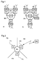
- FIG. 2 illustrates the sectoral division of the coverage area of a base station BS, which is part of the prior art, into, for example, three radio areas FB.
- the base station BS includes three transmission units UE, each of which provides a frequency channel FK for realizing the associated radio area FB.
- the base station is BS
- each frequency channel FK is divided into eight or 16 time slots (full rate or half rate) and each time slot can be assigned to another mobile station MS as the communication terminal of the radio system.
- the base station BS is connected to a mobile station MS via a transmission device UE and an air interface and thus enables the switching of a communication connection from the mobile station MS to other terminals in the communication network.
- FIG. 1 shows how a base station BS is expanded according to the invention by an additional transmission unit UEz in order to provide an additional frequency channel FK.
- the base station BS is controlled by a control device SE.
- the transmission devices UE each have a transmitting and receiving part TX / RX with the associated antenna elements for radiation and for receiving the transmitting or receiving energy.
- the additional transmission device UEz uses the transmitting and receiving parts TX / RX of the other transmission devices UE to implement the additional frequency channel FKz.
- the additional transmission device UEz according to FIG. 2 b) has its own transmitting and receiving part TX / RX for emitting the transmission energy or for receiving the reception energy of the additional frequency channel FKz.
- An additional frequency channel FKz can, as shown in FIG. 3, be divided into the radio areas FB in a wide variety of ways to supplement the already existing spectral resources FK.
- an additional frequency channel FKz according to FIG. 3 b) or 3 c) is assigned to several radio areas FB. This means that the additional frequency channel FKz realizes two or three radio areas FB.
- FIG 3 a indicates the case that one or Several frequency channels FK of a radio area FB, the guarantee of the function of the radio communication system in this radio area FB is jeopardized, so that the additional frequency channel FKz, which is basically provided for the supply of several radio areas FB, is used to replace the failed frequency channels FK in only one radio area FB becomes.
- FIG. 4 illustrates the problems of the effectiveness of the radio-technical use of resources when switching on additional frequency channels FKz.
- the market values plotted on the ordinate require the connection of an additional frequency channel FKz if a certain market value requirement is exceeded due to a further resource request.
- the additional frequency channel FKz is used for a single additional resource request, e.g. a request to start a call, underutilized.
- the effectiveness of resource utilization drops significantly, e.g. for a GSM system in time division multiplexing with a full rate utilization of the frequency channels FK, the connection of the second frequency channel FK leads to a deterioration in the effectiveness from approx.
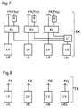
- the base station BS for example with three sectors and thus three radio areas FB, each implemented by a transmission device UE, are given below using block diagrams of the transmitting part TX in FIGS. 5 to 9 and the receiving part RX in FIGS. 10 and 11.
- the base station BS it is also possible for the base station BS to have only two or four or more radio areas FB; also the additional frequency channel FKz are only made available to a part of the radio areas FB.
- the solutions described below can be implemented both in full rate and in half rate mode.
- the power amplifiers LV of the transmission units UE and the additional transmission units UEz generate the transmission energy for the corresponding frequency channels FK.
- the power amplifier LV of the additional transmission unit UEz is connected to a magnetically controlled coaxial switch KoS.
- This coaxial switch KoS is controlled in time by a control device SE.
- the transmission energy of the additional frequency channel FKz is distributed by the coaxial switch KoS to the couplers Ko of the transmission devices UE for radiation on their antenna elements.
- Couplers Ko belonging to the transmission units UE are each connected on the input side to the power amplifiers LV and to a connection of the coaxial switch KoS.
- the couplers Ko can also be designed as a ring line. Part of the respective transmission energy is absorbed by a terminating resistor R.
- the combined transmission energies of the frequency channels FK and the additional frequency channel FKz are emitted by the antennas of the respective transmission units UE connected to the coupler Ko.
- the power amplifiers LV of the transmission units UE are connected directly to the corresponding antenna elements and implement the associated radio areas FB by making frequency channels FK available.
- a power amplifier LV of an additional transmission unit UEz is connected to a phase-controlled group antenna GA. Controlled by a control device SE, the transmission energy of the additional frequency channel FKz can be used by appropriate phase control of the individual antenna elements of the group antenna GA for several radio areas FB by switching over according to timing will.
- the radiation characteristic of the group antenna GA is aligned to a radio area FB for each time slot. According to this embodiment of the base station BS according to the invention, however (in contrast to the base station BS according to FIG. 5), no high-frequency transmission energy has to be switched.
- power amplifiers LV are each connected in the transmission unit TX in the transmission units UE to a coupler Ko, which can also be implemented by a ring line. Furthermore, the couplers Ko are each connected to a power amplifier LV of an additional transmission device UEz via a power divider LT. In the power divider LT, the transmission energy of the additional frequency channel FKz is divided between the three couplers Ko of the transmission units UE. Some of the transmission energies are each collected in a terminating resistor R and the combined transmission energy of the frequency channels FK of the transmission devices UE and of the additional frequency channel FKz of the additional transmission device UEz are each directed to the antenna elements for radiation. This solution does not require any control elements, however, in contrast to the base stations according to FIGS. 5 and 6, it is not possible to replace a frequency channel FK carrying the system information after failure in one of the radio areas FB.
- An additional transmission device UEz for generating an additional frequency channel FKz with power amplifier LV and antenna supplements the existing transmission devices UE for generating frequency channels FK with power amplifier LV and antenna in such a way that the antenna of the additional transmission device UEz emits omnidirectional or covers at least several radio areas FB Has radiation characteristics. Again, no controls or active elements are needed, but it's an additional one Antenna equipment is required and an organizational frequency channel replacement is not possible.
- the base station BS according to FIG. 9 is designed similarly to that according to FIG. However, the transmission energy of the frequency channels FK and the additional frequency channel FKz are combined before the final amplification.
- the transmission energy emitted by the modulators Mod of the transmission devices UE is in each case conducted to couplers Ko, which are also connected on the input side to a power divider LT.
- the power divider LT distributes the transmission energy of the frequency channel FKz generated in the modulator Mod of the additional transmission device UEz to the three transmission devices UE. Since the transmission energy before the final amplification is not so powerful, the power divider LT can also be replaced by a PIN diode PIN controlled by a control device SE.
- a part of the combined transmission energy of the frequency channels FK is absorbed in terminating resistors R and another part is amplified in linear power amplifiers LPA and routed to the corresponding antenna elements of the transmission part TX. If a PIN diode PIN is used, a replacement of a failed organization channel is also possible in this embodiment of the transmitting part TX.
- FIG. 10 shows a solution for the receiving part RX of a base station BS according to the invention.
- an additional transmission device UEz is provided, which is connected to an additional antenna A and carries out the evaluation of the additional frequency channel FKz.
- This solution is extremely simple, but it requires additional antenna equipment.
- An additional antenna is dispensed with in the base station BS according to FIG. 11.
- the reception energies of the frequency channels FK are received in the antennas of the respective transmission devices UE and are each routed to the broadband preamplifier RFE. Part of the received energy is led from the preamplifier into the corresponding receivers Rec of the transmission devices UE and additionally a further part of the received energy into a ring line RL.
- the filtering and amplification of the signals of the corresponding frequency channels FK, FKz takes place in the receiving devices Rec.
- the ring line RL can also be replaced by a PIN diode PIN controlled by a control device SE.
- the various solutions explained for the transmitting part TX and the receiving part RX can be combined as desired, they only have to be matched to the same radio areas FB.
- Particularly favorable combination possibilities are the implementation of a separate antenna in the transmitting and receiving part TX / RX for the additional frequency channel FKz, the transmission with power divider LT according to the solutions from FIG. 7 or FIG. 9 and reception with a receiving part RX according to FIG a PIN diode PIN.
Abstract
Description
In funktechnischen Kommunikationssystemen findet zumindestens ein Teil der Kommunikation zwischen zwei durch das funktechnische Kommunikationssystem vermittelten Kommunikationsendgeräte über eine Luftschnittstelle statt, d.h. über eine Funkverbindung. Eine solche Luftschnittstelle verfügt nur über begrenzte funktechnische Ressourcen. Die funktechnischen Ressourcen, wie der Umfang des zur Verfügung stehende Frequenzspektrum und die zur Verfügung stehende Zeit, müssen insbesondere für die Planung eines funktechnischen Netzes besonders rationell zugeteilt werden.In radio communication systems, at least part of the communication between two communication terminals mediated by the radio communication system takes place via an air interface, i.e. over a radio link. Such an air interface has only limited radio resources. The radio resources, such as the scope of the available frequency spectrum and the time available, must be allocated particularly efficiently, especially for the planning of a radio network.
Das GSM-Mobilfunknetz ist ein derartiges funktechnisches Kommunikationssystem, in dem sich die Luftschnittstelle zwischen ortsfesten Basisstationen und Mobilstationen befindet und die Kommunikation zwischen diesen regelt. Eine Basisstation verfügt dabei über mehrere Übertragungseinrichtungen, die jeweils einen Funkbereich mit funktechnischen Ressourcen versorgen und die für die Kommunikation mit den sich in diesem Funkbereich befindlichen Mobilstationen vorgesehen sind. Die funktechnischen Ressourcen einer Übertragungseinrichtung stellen die Frequenzkanäle dar, wovon zumindest ein Frequenzkanal zur Übertragung der Systeminformation erforderlich ist, und die Zeitlagen innerhalb eines Frequenzkanals, die auf mehrere Mobilstationen, also auf mehrere Kommunikationsendgeräte verteilt werden können.The GSM mobile radio network is such a radio communication system in which the air interface is located between fixed base stations and mobile stations and regulates the communication between them. A base station has several transmission devices, each of which supplies a radio area with radio resources and which are provided for communication with the mobile stations located in this radio area. The radio resources of a transmission device represent the frequency channels, of which at least one frequency channel is required to transmit the system information, and the time slots within a frequency channel, which can be distributed to several mobile stations, that is to say to several communication terminals.
In einem GSM-Netz wird zumeist Flächendeckung angestrebt, so daß die Funkbereiche der Übertragungseinrichtungen einer Basisstation in der Regel ein geschlossenes Versorgungsgebiet um die Basisstation herum bilden. Die durch die Übertragungseinrichtungen in einer Basisstation verwendeten Frequenzkanäle müssen sich hinsichtlich der Frequenz zur Verhinderung von Interferenzen voneinander unterscheiden, ebenso wie sich die Frequenzkanäle von den Frequenzkanälen benachbarter Funkbereiche anderer Basisstationen, also anderer Funkzellen, unterscheiden müssen. Da einem Netzbetreiber nur eine bestimmte Bandbreite im Frequenzspektrum für das funktechnische Kommunikationssystem zur Verfügung steht, steht er vor der komplexen Aufgabe, die zur Verfügung stehenden funktechnischen Ressourcen, zumeist die Frequenzkanäle, rationell unter Berücksichtigung der Verkehrswerte auf die Basisstationen und letztlich Übertragungseinrichtungen aufzuteilen.In a GSM network, coverage is usually sought, so that the radio areas of the transmission devices of a base station generally form a closed coverage area around the base station. The frequency channels used by the transmitters in a base station must differ from one another with regard to the frequency in order to prevent interference, just as the frequency channels must differ from the frequency channels of adjacent radio areas of other base stations, that is to say other radio cells. Since a network operator has only a certain bandwidth available in the frequency spectrum for the radio communication system, he is faced with the complex task of rationally distributing the available radio resources, usually the frequency channels, to the base stations and ultimately the transmission facilities, taking into account the market values.
Sind die funktechnischen Ressourcen einer Übertragungseinrichtung vollständig ausgelastet und eine neue Ressourcenanforderung, z.B. für einen weiteren Gesprächsaufbau, liegt vor, so müssen diesem Funkbereich zusätzliche spektrale Ressourcen zur Verfügung gestellt werden. Ein zusätzlicher Frequenzkanal für diesen Funkbereich bedeutet jedoch beim Zeitlagenmultiplexverfahren, daß für den einen Gesprächsaufbauwunsch eine erhebliche Überkapazität an funktechnischen Ressourcen (hier Zeitlagen) angeboten wird, die nicht genutzt wird. Diese angebotene Überkapazität für nur einen Funkbereich führt insbesondere für Basisstationen in Gebieten geringer Nutzung des Funknetzes z.B. in ländlichen Gebieten, wo nur wenige Frequenzkanäle angeboten werden müssen, zu einer deutlichen Verminderung der Effektivität der Auslastung der angebotenen funktechnischen Ressourcen und damit zu einer unrationellen Aufteilung der funktechnischen Ressourcen.Are the radio resources of a transmission facility fully utilized and a new resource request, e.g. for a further call setup, additional spectral resources must be made available to this radio area. However, an additional frequency channel for this radio range means in the time division multiplex method that a considerable excess capacity of radio technical resources (here time positions) is offered for one call setup request, which is not used. This offered excess capacity for only one radio area leads in particular to base stations in areas where the radio network is not used, e.g. in rural areas, where only a few frequency channels have to be offered, to a significant reduction in the effectiveness of the utilization of the offered radio resources and thus to an inefficient distribution of the radio resources.
Aus dem Motorola "BSS Equipment Planning Guide" von 1992 ist eine Lösung bekannt, die es ermöglicht, die eingesetzten Baugruppen effizienter zu nutzen. Dies geschieht, indem eine zusätzliche Übertragungseinrichtung einer Basisstation zugeordnet wird, die in der Lage ist, in alle durch die Basisstation und deren Übertragungseinrichtungen realisierte Funkbereiche zu senden oder von dort zu empfangen. Es wird jedoch für jeden Funkbereich der Basisstation eine neue zusätzliche Frequenz, also ein zusätzlicher Frequenzkanal, zugeteilt. Die zusätzliche Übertragungseinrichtung muß also zwischen den Frequenzkanälen zeitlagengetreu umschalten. Damit wird die zusätzliche Übertragungseinrichtung zwar effizienter ausgelastet, da Ressourcenanforderungen aus allen zur Basisstation gehörigen Funkbereichen bedient werden können, jedoch findet eine große Inanspruchnahme von zusätzlichen spektralen Ressourcen (drei zusätzliche Frequenzkanäle) statt. Die spektralen Ressourcen werden dadurch weiterhin ungenügend ausgelastet.A solution is known from the Motorola "BSS Equipment Planning Guide" from 1992, which makes it possible to use the modules used more efficiently. This is done by assigning an additional transmission device to a base station, which is able to transmit to or receive from all radio areas realized by the base station and its transmission devices. However, there is a new additional frequency for each radio area of the base station, an additional frequency channel. The additional transmission device must therefore switch between the frequency channels according to the time position. The additional transmission device is thus utilized more efficiently, since resource requests from all radio areas belonging to the base station can be served, but there is a great use of additional spectral resources (three additional frequency channels). As a result, the spectral resources are still underutilized.
Der Erfindung liegt die Aufgabe zugrunde, für Basisstationen in funktechnischen Systemen die funktechnischen Ressourcen so auf die Übertragungseinrichtungen aufzuteilen, daß eine hohe Auslastung der Ressourcen ermöglicht wird. Diese Aufgabe wird erfindungsgemäß durch das Verfahren nach den Merkmalen des Patentanspruches 1 gelöst. In einem unabhängigen Anspruch wird eine erfindungsgemäße Basisstation angegeben.The invention has for its object to divide the radio resources for base stations in radio systems on the transmission devices so that a high utilization of resources is made possible. This object is achieved by the method according to the features of
Der erfindungswesentliche Aspekt liegt darin, zusätzliche spektrale Ressourcen vorzusehen, die im Fall einer weiteren Ressourcenanforderung bei Nichtverfügbarkeit der bisher zur Verfügung stehenden funktechnischen Ressourcen für zumindest zwei der Übertragungseinrichtungen der Basisstation zur gemeinsamen Nutzung zugeteilt werden. Dies bedeutet, daß die zusätzlichen spektralen Ressourcen durch ihre gleichzeitige Nutzung für mehrere Funkbereiche effizienter ausgenutzt werden.The aspect essential to the invention is to provide additional spectral resources which, in the event of a further resource request, if the previously available radio resources are not available for shared use by at least two of the transmission devices of the base station. This means that the additional spectral resources can be used more efficiently by their simultaneous use for several radio areas.
Für einen Netzbetreiber z.B. in einem GSM-Netz bedeutet dies, daß er z.B. für ein Gebiet in seinem Funknetz, das durch eine Basisstation mit drei sektorisierten Übertragungseinrichtungen versorgt wird, die jeweils einen Frequenzkanal aufweisen, durch die Zuteilung eines zusätzlichen Frequenzkanals für alle drei Funkbereiche unter Zuhilfenahme eines Minimums an zusätzlichen spektralen Ressourcen geringe Überlastspitzen abfangen kann. Das erfindungsgemäße Verfahren eignet sich insbesondere für den Einsatz in GSM- oder DECT-Mobilfunksystemen, in dem die spektralen Ressourcen durch Frequenzkanäle realisiert sind, wobei ein Frequenzkanal in mehrere Zeitlagen unterteilt ist (Zeitlagenmultiplexverfahren), die wiederum auf verschiedene Kommunikationsverbindungen verteilt werden können. Somit ist es möglich, daß die Aufteilung eines zusätzlichen Frequenzkanals auf mehrere Funkbereiche durch Verteilen von Zeitlagen auf einfachste Weise realisiert werden kann.For a network operator, for example in a GSM network, this means that, for example, for an area in its radio network that is supplied by a base station with three sectored transmission devices, each having a frequency channel, by allocating an additional frequency channel for all three radio areas A minimum of additional spectral resources can intercept low overload peaks. The method according to the invention is suitable in particular for use in GSM or DECT mobile radio systems, in which the spectral resources are implemented by frequency channels, a frequency channel being divided into several time slots (time slot multiplex method), which in turn can be distributed over different communication links. It is thus possible for the division of an additional frequency channel into a plurality of radio areas to be realized in the simplest way by distributing time slots.
Nach einer weiteren vorteilhaften Ausprägung des erfindungsgemäßen Verfahrens wird ein ![]()
![]()
![]()
![]()
Die Möglichkeit, einen zusätzlichen Frequenzkanal für mehrere Funkbereiche nutzbar zu machen, kann auch dahingehend ausgenutzt werden, indem dieser zusätzliche Frequenzkanal beim Ausfall eines die Systeminformation tragenden Frequenzkanals einer der bereits vorhandenen Übertragungseinrichtungen als Ersatzkanal eingesetzt werden kann - Anspruch 5. Das funktechnische Kommunikationssystem gewinnt dadurch vorteilhafterweise an Funktionssicherheit.The possibility of making an additional frequency channel usable for several radio ranges can also be exploited to the extent that this additional frequency channel can be used as a replacement channel in the event of the failure of a frequency channel carrying the system information of one of the already existing transmission devices - claim 5. The radio communication system thereby advantageously wins in functional safety.
In einem unabhängigen Anspruch und den darauf rückbezogenen Unteransprüchen wird eine Basisstation angegeben, bei der die funktechnischen Ressourcen derart auf die Übertragungseinrichtungen aufgeteilt werden, daß eine hohe Auslastung der Ressourcen möglich ist.In an independent claim and the dependent claims referring to it, a base station is specified in which the radio resources are distributed among the transmission devices in such a way that a high utilization of the resources is possible.
Das erfindungsgemäße Verfahren und die erfindungsgemäße Basisstation werden im folgenden anhand von Ausführungsbeispielen näher erläutert.The method according to the invention and the base station according to the invention are explained in more detail below on the basis of exemplary embodiments.
Hierzu zeigen
- FIG 1
- Basisstationen mit zugehörigen Einrichtungen zur Realisierung der Funkbereiche, insbesondere einer zusätzlichen Übertragungseinrichtung,
- FIG 2
- eine Basisstation nach dem Stand der Technik mit zugehörigen Funkbereichen,
- FIG 3
- verschiedene Möglichkeiten zur Aufteilung einer zusätzlichen spektralen Ressource auf ein oder mehrere Funkbereiche,
- FIG 4
- die Effektivität der Auslastung der funktechnischen Ressourcen in Abhängigkeit von den zur Verfügung gestellten Frequenzkanälen und den Ressourcenanforderungen,
- FIG 5 bis 9
- Blockschaltbilder von Teilen des Sendeteils der Übertragungseinrichtungen der Basisstation und
- FIG 10 und 11
- Blockschaltbilder von Teilen des Empfangsteils der Übertragungseinrichtungen einer Basisstation.
- FIG. 1
- Base stations with associated devices for implementing the radio areas, in particular an additional transmission device,
- FIG 2
- a base station according to the prior art with associated radio areas,
- FIG 3
- various options for dividing an additional spectral resource into one or more radio areas,
- FIG 4
- the effectiveness of the utilization of the radio resources depending on the frequency channels made available and the resource requirements,
- 5 to 9
- Block diagrams of parts of the transmitting part of the transmission devices of the base station and
- 10 and 11
- Block diagrams of parts of the receiving part of the transmission devices of a base station.
In FIG 2 ist die zum Stand der Technik gehörende sektorisierende Aufteilung des Versorgungsbereiches einer Basisstation BS in z.B. drei Funkbereiche FB verdeutlicht. Zur Basisstation BS gehören drei Übertragungseinheiten UE, die zur Realisierung des zugehörigen Funkbereiches FB jeweils einen Frequenzkanal FK zur Verfügung stellen. Die Basisstation BS ist z.B. Teil eines GSM-Mobilfunksystems, bei dem jeder Frequenzkanal FK in acht bzw. 16 Zeitlagen unterteilt ist (Full-Rate bzw. Half-Rate) und jede Zeitlage einer anderen Mobilstation MS als Kommunikationsendgerät des funktechnischen Systems zugeteilt werden kann. Die Basisstation BS ist über eine Übertragungseinrichtung UE und eine Luftschnittstelle mit einer Mobilstation MS verbunden und ermöglicht so die Vermittlung einer Kommunikationsverbindung von Mobilstation MS zu anderen Endgeräten im Kommunikationsnetz.FIG. 2 illustrates the sectoral division of the coverage area of a base station BS, which is part of the prior art, into, for example, three radio areas FB. The base station BS includes three transmission units UE, each of which provides a frequency channel FK for realizing the associated radio area FB. The base station is BS For example, part of a GSM mobile radio system in which each frequency channel FK is divided into eight or 16 time slots (full rate or half rate) and each time slot can be assigned to another mobile station MS as the communication terminal of the radio system. The base station BS is connected to a mobile station MS via a transmission device UE and an air interface and thus enables the switching of a communication connection from the mobile station MS to other terminals in the communication network.
In FIG 1 ist angegeben, wie eine Basisstation BS erfindungsgemäß durch eine zusätzliche Übertragungseinheit UEz erweitert wird, um einen zusätzlichen Frequenzkanal FK zur Verfügung zu stellen. Die Basisstation BS wird dabei durch eine Steuereinrichtung SE gesteuert. Es gibt dabei zwei prinzipiell unterschiedliche Lösungen entsprechend den FIG 2 a) und 2 b). In FIG 2 a) verfügen die Übertragungseinrichtungen UE jeweils über einen Sende- und Empfangsteil TX/RX mit den zugehörigen Antennenelementen zur Abstrahlung und zum Empfang der Sende- bzw. Empfangsenergie. Die zusätzliche Übertragungseinrichtung UEz verwendet die Sende- und Empfangsteile TX/RX der anderen Übertragungseinrichtungen UE zur Realisierung des zusätzlichen Frequenzkanals FKz. Im Gegensatz dazu verfügt die zusätzliche Übertragungseinrichtung UEz gemäß FIG 2 b) über einen eigenen Sende- und Empfangsteil TX/RX zur Abstrahlung der Sendeenergie bzw. zum Empfang der Empfangsenergie des zusätzlichen Frequenzkanals FKz.1 shows how a base station BS is expanded according to the invention by an additional transmission unit UEz in order to provide an additional frequency channel FK. The base station BS is controlled by a control device SE. There are two fundamentally different solutions in accordance with FIGS. 2a) and 2b). 2 a), the transmission devices UE each have a transmitting and receiving part TX / RX with the associated antenna elements for radiation and for receiving the transmitting or receiving energy. The additional transmission device UEz uses the transmitting and receiving parts TX / RX of the other transmission devices UE to implement the additional frequency channel FKz. In contrast to this, the additional transmission device UEz according to FIG. 2 b) has its own transmitting and receiving part TX / RX for emitting the transmission energy or for receiving the reception energy of the additional frequency channel FKz.
Ein zusätzlicher Frequenzkanal FKz kann dabei, wie in FIG 3 dargestellt, auf unterschiedlichste Weise zur Ergänzung der bereits vorhandenen spektralen Ressourcen FK auf die Funkbereiche FB aufgeteilt werden. Für eine Basisstation BS mit drei Sektoren, also drei Funkbereichen FB, wird ein zusätzlicher Frequenzkanal FKz gemäß FIG 3 b) oder 3 c) mehreren Funkbereichen FB zugeteilt. Dies bedeutet, der zusätzliche Frequenzkanal FKz realisiert zwei oder drei Funkbereiche FB. FIG 3 a) gibt den Fall an, daß durch den Ausfall einer oder mehrerer Frequenzkanäle FK eines Funkbereiches FB die Gewährleistung der Funktion des funktechnischen Kommunikationssystems in diesem Funkbereich FB gefährdet ist, so daß der zusätzliche Frequenzkanal FKz, der prinzipiell für die Versorgung mehrerer Funkbereiche FB vorgesehen ist, zum Ersatz der ausgefallenen Frequenzkanäle FK in nur einem Funkbereich FB eingesetzt wird.An additional frequency channel FKz can, as shown in FIG. 3, be divided into the radio areas FB in a wide variety of ways to supplement the already existing spectral resources FK. For a base station BS with three sectors, ie three radio areas FB, an additional frequency channel FKz according to FIG. 3 b) or 3 c) is assigned to several radio areas FB. This means that the additional frequency channel FKz realizes two or three radio areas FB. FIG 3 a) indicates the case that one or Several frequency channels FK of a radio area FB, the guarantee of the function of the radio communication system in this radio area FB is jeopardized, so that the additional frequency channel FKz, which is basically provided for the supply of several radio areas FB, is used to replace the failed frequency channels FK in only one radio area FB becomes.
FIG 4 verdeutlicht die Probleme der Effektivität der funktechnischen Ressourcenausnutzung beim Zuschalten zusätzlicher Frequenzkanäle FKz. Die auf die Ordinate aufgetragenen Verkehrswerte erfordern beim Übersteigen eines gewissen Verkehrswertbedürfnisses durch eine weitere Ressourcenanforderung das Zuschalten eines zusätzlichen Frequenzkanals FKz. Der zusätzliche Frequenzkanal FKz wird jedoch bei einer einzigen zusätzlichen Ressourcenanforderung, z.B. einer Aufforderung zu einem Gesprächsaufbau, nur ungenügend ausgelastet. Dies führt dazu, daß die Effektivität der Ressourcenausnutzung erheblich zurückgeht, z.B. für ein GSM-System im Zeitlagenmultiplexverfahren mit einer Full-Rate-Ausnutzung der Frequenzkanäle FK führt das Zuschalten des zweiten Frequenzkanals FK bei einer weiteren Gesprächsanforderung zu einer Verschlechterung der Effektivität von ca. 45 % auf 20 % und für eine Ausnutzung der Frequenzkanäle in Half-Rate von ca. 60 % auf 25 %. Die in diesen Fällen ungenutzten sieben bzw. 15 Zeitlagen könnten im Sinne des erfindungsgemäßen Verfahrens auf weitere Funkbereiche FB, aus denen eventuell ebenfalls weitere Gesprächsaufforderungen vorliegen, aufgeteilt werden.4 illustrates the problems of the effectiveness of the radio-technical use of resources when switching on additional frequency channels FKz. The market values plotted on the ordinate require the connection of an additional frequency channel FKz if a certain market value requirement is exceeded due to a further resource request. However, the additional frequency channel FKz is used for a single additional resource request, e.g. a request to start a call, underutilized. As a result, the effectiveness of resource utilization drops significantly, e.g. for a GSM system in time division multiplexing with a full rate utilization of the frequency channels FK, the connection of the second frequency channel FK leads to a deterioration in the effectiveness from approx. 45% to 20% in the case of a further call request and for an utilization of the frequency channels in half Rate from around 60% to 25%. The seven or 15 time slots not used in these cases could, in the sense of the method according to the invention, be divided up into further radio areas FB, from which further call requests may also be present.
Verschiedene Realisierungsmöglichkeiten der erfindungsgemäßen Basisstation BS mit z.B. drei Sektoren und damit drei durch jeweils eine Übertragungseinrichtung UE realisierten Funkbereich FB werden im folgenden anhand von Blockschaltbildern des Sendeteils TX in den FIG 5 bis 9 und des Empfangsteils RX in den FIG 10 und 11 angegeben. Es ist jedoch auch möglich, daß die Basisstation BS über nur zwei bzw. vier oder mehr Funkbereiche FB verfügt; auch kann der zusätzliche Frequenzkanal FKz nur einem Teil der Funkbereiche FB zur Verfügung gestellt werden. Für Anwendungen innerhalb des GSM- Systems sind die im folgenden geschilderten Lösungen sowohl im Full-Rate als auch im Half-Rate Betrieb realisierbar.Various possible implementations of the base station BS according to the invention, for example with three sectors and thus three radio areas FB, each implemented by a transmission device UE, are given below using block diagrams of the transmitting part TX in FIGS. 5 to 9 and the receiving part RX in FIGS. 10 and 11. However, it is also possible for the base station BS to have only two or four or more radio areas FB; also the additional frequency channel FKz are only made available to a part of the radio areas FB. For applications within the GSM system, the solutions described below can be implemented both in full rate and in half rate mode.
In FIG 5 erzeugen die Leistungsverstärker LV der Übertragungseinheiten UE und der zusätzlichen Übertragungseinheiten UEz die Sendeenergie für die entsprechenden Frequenzkanäle FK. Der Leistungsverstärker LV der zusätzlichen Übertragungseinheit UEz ist mit einem magnetisch gesteuerten Koaxialschalter KoS verbunden. Dieser Koaxialschalter KoS wird durch eine Steuereinrichtung SE zeitlagengemäß gesteuert. Die Sendeenergie des zusätzlichen Frequenzkanals FKz wird durch den Koaxialschalter KoS auf die Koppler Ko der Übertragungseinrichtungen UE zur Abstrahlung auf deren Antennenelemente verteilt. Den Übertragungseinheiten UE zugehörige Koppler Ko sind jeweils mit den Leistungsverstärkern LV und einem Anschluß des Koaxialschalters KoS eingangsseitig verbunden. Die Koppler Ko können auch als Ringleitung ausgeprägt sein. Ein Teil der jeweiligen Sendeenergie wird jeweils durch einen Abschlußwiderstand R absorbiert. Die zusammengeführten Sendeenergien der Frequenzkanäle FK und des zusätzlichen Frequenzkanals FKz werden durch die jeweils mit dem Koppler Ko verbundenen Antennen der jeweiligen Übertragungseinheiten UE abgestrahlt.5, the power amplifiers LV of the transmission units UE and the additional transmission units UEz generate the transmission energy for the corresponding frequency channels FK. The power amplifier LV of the additional transmission unit UEz is connected to a magnetically controlled coaxial switch KoS. This coaxial switch KoS is controlled in time by a control device SE. The transmission energy of the additional frequency channel FKz is distributed by the coaxial switch KoS to the couplers Ko of the transmission devices UE for radiation on their antenna elements. Couplers Ko belonging to the transmission units UE are each connected on the input side to the power amplifiers LV and to a connection of the coaxial switch KoS. The couplers Ko can also be designed as a ring line. Part of the respective transmission energy is absorbed by a terminating resistor R. The combined transmission energies of the frequency channels FK and the additional frequency channel FKz are emitted by the antennas of the respective transmission units UE connected to the coupler Ko.
In der Basisstation BS gemäß FIG 6 sind die Leistungsverstärker LV der Übertragungseinheiten UE direkt mit den entsprechenden Antennenelementen verbunden und realisieren die zugehörigen Funkbereiche FB durch ein Zurverfügungstellen von Frequenzkanälen FK. Ein Leistungsverstärker LV einer zusätzlichen Übertragungseinheit UEz ist mit einer phasengesteuerten Gruppenantenne GA verbunden. Gesteuert durch eine Steuereinrichtung SE, kann die Sendeenergie des zusätzlichen Frequenzkanals FKz durch entsprechende Phasenansteuerung der einzelnen Antennenelemente der Gruppenantenne GA für mehrere Funkbereiche FB durch zeitlagengemäßes Umschalten genutzt werden. Die Abstrahlungscharakteristik der Gruppenantenne GA wird für jede Zeitlage auf jeweils einen Funkbereich FB ausgerichtet. Nach dieser Ausführungsform der erfindungsgemäßen Basisstation BS muß jedoch (im Gegensatz zur Basisstation BS nach FIG 5) keine hochfrequente Sendeenergie geschaltet werden.In the base station BS according to FIG. 6, the power amplifiers LV of the transmission units UE are connected directly to the corresponding antenna elements and implement the associated radio areas FB by making frequency channels FK available. A power amplifier LV of an additional transmission unit UEz is connected to a phase-controlled group antenna GA. Controlled by a control device SE, the transmission energy of the additional frequency channel FKz can be used by appropriate phase control of the individual antenna elements of the group antenna GA for several radio areas FB by switching over according to timing will. The radiation characteristic of the group antenna GA is aligned to a radio area FB for each time slot. According to this embodiment of the base station BS according to the invention, however (in contrast to the base station BS according to FIG. 5), no high-frequency transmission energy has to be switched.
Für die Basisstation BS gemäß FIG 7 sind im Sendeteil TX Leistungsverstärker LV in den Übertragungseinheiten UE jeweils mit einem Koppler Ko, der auch durch eine Ringleitung realisiert werden kann, verbunden. Des weiteren sind die Koppler Ko jeweils mit einem Leistungsverstärker LV einer zusätzlichen Übertragungseinrichtung UEz über einen Leistungsteiler LT verbunden. Im Leistungsteiler LT wird die Sendeenergie des zusätzlichen Frequenzkanals FKz auf die drei Koppler Ko der Übertragungseinheiten UE aufgeteilt. Ein Teil der Sendeenergien wird jeweils in einem Abschlußwiderstand R aufgefangen und die zusammengeführte Sendeenergie der Frequenzkanäle FK der Übertragungseinrichtungen UE und des zusätzlichen Frequenzkanals FKz der zusätzlichen Übertragungseinrichtung UEz jeweils auf die Antennenelemente zur Abstrahlung geführt. Diese Lösung erfordert keinerlei Steuerelemente, es ist jedoch im Gegensatz zu den Basisstationen nach den FIG 5 und 6 kein Ersatz eines die Systeminformation tragenden Frequenzkanals FK nach Ausfall in einem der Funkbereiche FB möglich.For the base station BS according to FIG. 7, power amplifiers LV are each connected in the transmission unit TX in the transmission units UE to a coupler Ko, which can also be implemented by a ring line. Furthermore, the couplers Ko are each connected to a power amplifier LV of an additional transmission device UEz via a power divider LT. In the power divider LT, the transmission energy of the additional frequency channel FKz is divided between the three couplers Ko of the transmission units UE. Some of the transmission energies are each collected in a terminating resistor R and the combined transmission energy of the frequency channels FK of the transmission devices UE and of the additional frequency channel FKz of the additional transmission device UEz are each directed to the antenna elements for radiation. This solution does not require any control elements, however, in contrast to the base stations according to FIGS. 5 and 6, it is not possible to replace a frequency channel FK carrying the system information after failure in one of the radio areas FB.
Eine weitere Möglichkeit zur Realisierung einer erfindungsgemäßen Basisstation BS ist in FIG 8 erläutert. Eine zusätzliche Übertragungseinrichtung UEz zur Erzeugung eines zusätzlichen Frequenzkanals FKz mit Leistungsverstärker LV und Antenne ergänzt die vorhandenen Übertragungseinrichtungen UE zur Erzeugung von Frequenzkanälen FK mit Leistungsverstärker LV und Antenne in der Art, daß die Antenne der zusätzlichen Übertragungseinrichtung UEz omnidirektional abstrahlt oder eine zumindest mehrere Funkbereiche FB abdeckende Abstrahlungscharakteristik aufweist. Auch hier werden keine Steuer- oder aktiven Elemente benötigt, doch es ist eine zusätzliche Antennenausrüstung erforderlich und ein Organisationsfrequenzkanalersatz ist nicht möglich.Another possibility for realizing a base station BS according to the invention is explained in FIG. An additional transmission device UEz for generating an additional frequency channel FKz with power amplifier LV and antenna supplements the existing transmission devices UE for generating frequency channels FK with power amplifier LV and antenna in such a way that the antenna of the additional transmission device UEz emits omnidirectional or covers at least several radio areas FB Has radiation characteristics. Again, no controls or active elements are needed, but it's an additional one Antenna equipment is required and an organizational frequency channel replacement is not possible.
Die Basisstation BS gemäß FIG 9 ist ähnlich der nach FIG 7 gestaltet. Es findet hierbei jedoch das Zusammenführen der Sendeenergie der Frequenzkanäle FK und des zusätzlichen Frequenzkanals FKz vor der Endverstärkung statt. Die von den Modulatoren Mod der Übertragungseinrichtungen UE abgegebene Sendeenergie wird jeweils auf Koppler Ko geführt, die weiterhin eingangsseitig mit einem Leistungsteiler LT verbunden sind. Der Leistungsteiler LT teilt die Sendeenergie des im Modulator Mod der zusätzlichen Übertragungseinrichtung UEz erzeugten Frequenzkanals FKz auf die drei Übertragungseinrichtungen UE auf. Da die Sendeenergie vor der Endverstärkung nicht so leistungsstark ist, kann der Leistungsteiler LT auch durch eine durch eine Steuereinrichtung SE gesteuerte PIN-Diode PIN ersetzt werden. Ausgangsseitig zu den Kopplern Ko wird jeweils ein Teil der zusammengeführten Sendeenergie der Frequenzkanäle FK in Abschlußwiderständen R absorbiert und ein weiterer Teil in linearen Leistungsverstärkern LPA endverstärkt und auf die entsprechenden Antennenelemente des Sendeteils TX geführt. Bei einem Einsatz einer PIN-Diode PIN ist auch bei dieser Ausführungsform des Sendeteils TX ein Ersatz eines ausgefallenen Organisationskanals möglich.The base station BS according to FIG. 9 is designed similarly to that according to FIG. However, the transmission energy of the frequency channels FK and the additional frequency channel FKz are combined before the final amplification. The transmission energy emitted by the modulators Mod of the transmission devices UE is in each case conducted to couplers Ko, which are also connected on the input side to a power divider LT. The power divider LT distributes the transmission energy of the frequency channel FKz generated in the modulator Mod of the additional transmission device UEz to the three transmission devices UE. Since the transmission energy before the final amplification is not so powerful, the power divider LT can also be replaced by a PIN diode PIN controlled by a control device SE. On the output side to the couplers Ko, a part of the combined transmission energy of the frequency channels FK is absorbed in terminating resistors R and another part is amplified in linear power amplifiers LPA and routed to the corresponding antenna elements of the transmission part TX. If a PIN diode PIN is used, a replacement of a failed organization channel is also possible in this embodiment of the transmitting part TX.
In FIG 10 ist eine Lösung für den Empfangsteil RX einer erfindungsgemäßen Basisstation BS dargestellt. Parallel zu den Empfangsteilen der Übertragungseinrichtungen UE zum Empfang der Frequenzkanäle FK mit den zugehörigen Antennenelementen ist eine zusätzliche Übertragungseinrichtung UEz vorgesehen, die mit einer zusätzlichen Antenne A verbunden ist und die Auswertung des zusätzlichen Frequenzkanals FKz vornimmt. Diese Lösung ist äußerst einfach, jedoch erfordert sie eine zusätzliche Antennenausrüstung.10 shows a solution for the receiving part RX of a base station BS according to the invention. In parallel to the receiving parts of the transmission devices UE for receiving the frequency channels FK with the associated antenna elements, an additional transmission device UEz is provided, which is connected to an additional antenna A and carries out the evaluation of the additional frequency channel FKz. This solution is extremely simple, but it requires additional antenna equipment.
Bei der Basisstation BS nach FIG 11 wird auf eine zusätzliche Antenne verzichtet. Die Empfangsenergien der Frequenzkanäle FK werden in den Antennen der jeweiligen Übertragungseinrichtungen UE empfangen und jeweils auf die breitbandigen Vorverstärker RFE geführt. Ein Teil der Empfangsenergie wird aus dem Vorverstärker in die entsprechenden Empfänger Rec der Übertragungseinrichtungen UE und zusätzlich ein weiterer Teil der Empfangsenergie in eine Ringleitung RL geführt. Die Ringleitung RL für die Empfangsenergien, die aus den verschiedenen Funkbereichen FB stammen, führt die zusammengeführten Empfangsenergien in den Empfangsteil Rec der zusätzlichen Übertragungseinrichtung UEz. In den Empfangseinrichtungen Rec findet jeweils die Filterung und Verstärkung der Signale der entsprechenden Frequenzkanäle FK, FKz statt. Die Ringleitung RL kann ebenfalls durch eine durch eine Steuereinrichtung SE gesteuerte PIN-Diode PIN ersetzt werden. Diese Lösungen benötigen keinen zusätzlichen Aufwand an Antennenausrüstung, es treten jedoch zusätzliche Verluste auf und eine geringere Sensibilität beim Empfang ist zu verzeichnen.An additional antenna is dispensed with in the base station BS according to FIG. 11. The reception energies of the frequency channels FK are received in the antennas of the respective transmission devices UE and are each routed to the broadband preamplifier RFE. Part of the received energy is led from the preamplifier into the corresponding receivers Rec of the transmission devices UE and additionally a further part of the received energy into a ring line RL. The ring line RL for the reception energies, which originate from the different radio areas FB, leads the merged reception energies into the reception part Rec of the additional transmission device UEz. The filtering and amplification of the signals of the corresponding frequency channels FK, FKz takes place in the receiving devices Rec. The ring line RL can also be replaced by a PIN diode PIN controlled by a control device SE. These solutions do not require additional antenna equipment, but there are additional losses and less sensitivity to reception.
Die verschiedenen erläuterten Lösungen für den Sendeteil TX und den Empfangsteil RX können beliebig kombiniert werden, sie müssen lediglich auf die gleichen Funkbereiche FB abgestimmt sein. Besonders günstige Kombinationsmöglichkeiten sind das Realisieren einer gesonderten Antenne jeweils im Sende- und Empfangsteil TX/RX für den zusätzlichen Frequenzkanal FKz, sowie das Senden mit Leistungsteiler LT nach den Lösungen aus FIG 7 ode FIG 9 und ein Empfang mit einem Empfangsteil RX nach FIG 11 mit einer PIN-Diode PIN.The various solutions explained for the transmitting part TX and the receiving part RX can be combined as desired, they only have to be matched to the same radio areas FB. Particularly favorable combination possibilities are the implementation of a separate antenna in the transmitting and receiving part TX / RX for the additional frequency channel FKz, the transmission with power divider LT according to the solutions from FIG. 7 or FIG. 9 and reception with a receiving part RX according to FIG a PIN diode PIN.
Claims (17)
bei dem
in which
dadurch gekennzeichnet,
daß das funktechnische Kommunikationssystem als ein im Zeitlangenmulitplexverfahren betriebenes Funksystem ausgeprägt ist und die vorgesehenen zusätzlichen spektralen Ressourcen (FKz) zumindest ein zusätzlicher Frequenzkanal sind.Method according to claim 1,
characterized,
that the radio communication system is designed as a radio system operated in time-length multiplexing and the additional spectral resources (FKz) provided are at least one additional frequency channel.
dadurch gekennzeichnet,
daß die Übertragungseinrichtungen (UE) im Zeitlagenmultiplexverfahren betrieben werden und die Zeitlagen des zumindest einen zusätzlichen Frequenzkanals (FKz) auf die zumindest zwei Übertragungseinrichtungen (UE) aufgeteilt werden.Method according to claim 2,
characterized,
that the transmission devices (UE) are operated in time slot multiplexing and the time slots of the at least one additional frequency channel (FKz) are divided between the at least two transmission devices (UE).
dadurch gekennzeichnet,
daß ein Frequenzkanal (FKz) zusätzlich verfügbar gemacht wird.Method according to claim 2 or 3,
characterized,
that a frequency channel (FKz) is also made available.
dadurch gekennzeichnet,
daß die Nutzung des zusätzlichen Frequenzkanals (FKz) durch die zumindest zwei Übertragungseinrichtungen (UE) eingeschränkt wird und der zusätzliche Frequenzkanal (FKz) zur Versorgung eines einzelnen Funkbereiches (FB) zur Verfügung gestellt wird.Method according to one of claims 1 to 4,
characterized,
that the use of the additional frequency channel (FKz) is restricted by the at least two transmission devices (UE) and the additional frequency channel (FKz) is provided to cover an individual radio area (FB).
wobei die Übertragungseinrichtungen (UE) jeweils einen Funkbereich (FB) realisieren, einen Sende- (TX) und Empfangsteil (RX) umfassen und von einer Steuereinrichtung (SE) gesteuert werden,
in der durch eine zusätzliche Übertragungseinrichtung (UEz) realisierte
wherein the transmission devices (UE) each implement a radio area (FB), comprise a transmitting (TX) and receiving section (RX) and are controlled by a control device (SE),
in the realized by an additional transmission facility (UEz)
in einem im Zeitlagenmultiplexverfahren betriebenen Funksystem,
wobei die zusätzlich vorgesehenen spektralen Ressourcen (FKz) zumindest einen zusätzlichen Frequenzkanal umfassen, dessen Zeitlagen (ZL) auf die zumindest zwei Übertragungseinrichtungen (UE) aufgeteilt werden.Base station according to claim 6,
in a time division multiplexed radio system,
the additionally provided spectral resources (FKz) include at least one additional frequency channel, the time slots (ZL) of which are divided between the at least two transmission devices (UE).
dadurch gekennzeichnet,
characterized,
dadurch gekennzeichnet,
daß eine zusätzliche, einen Frequenzkanal (FKz) generierende Übertragungseinrichtung (UEz) vorgesehen ist, die im Sendeteil (TX) mit einer zusätzlichen phasengesteuerten Gruppenantenne (GA) verbunden ist, so daß die Gruppenantenne (GA) gesteuert durch die Steuereinrichtung (SE) den zusätzlichen Frequenzkanal (FKz) zwischen den Funkbereichen (FB) zumindest zweier Übertragungseinrichtungen (UE) zeitlagengemäß umschalten kann.Base station according to claim 6 or 7,
characterized,
that an additional, a frequency channel (FKz) generating transmission device (UEz) is provided, which is connected in the transmitting part (TX) to an additional phase-controlled group antenna (GA), so that the group antenna (GA) controlled by the control device (SE) the additional Frequency channel (FKz) can switch between the radio areas (FB) of at least two transmission devices (UE) according to the timing.
dadurch gekennzeichnet,
daß eine zusätzliche, einen Frequenzkanal (FKz) generierende Übertragungseinrichtung (UEz) vorgesehen ist, die im Sendeteil (TX) jeweils mit einem Leistungsteiler (LT) verbunden sind, so daß die Sendeenergie des zusätzlichen Frequenzkanals (FKz) über den Leistungsteiler (LT) auf zumindest zwei weitere Übertragungseinrichtungen (UE) aufteilt und
mittels zusätzlicher in den weiteren Übertragungseinrichtungen (UE) angeordneter, mit dem Leistungsteiler (LT) verbundener Ringleitungen oder Koppler (Ko) die Sendeenergie des zusätzlichen Frequenzkanals (FKz) mit den Sendeenergien der jeweiligen Übertragungseinrichtungen (UE) zusammengeführt wird.Base station according to claim 6 or 7,
characterized,
that an additional, a frequency channel (FKz) generating transmission device (UEz) is provided, which are each connected to a power divider (LT) in the transmission part (TX), so that the transmission energy of the additional frequency channel (FKz) via the power divider (LT) divides at least two further transmission devices (UE) and
by means of additional ring lines or couplers (Ko) arranged in the further transmission devices (UE) and connected to the power divider (LT), the transmission energy of the additional frequency channel (FKz) is combined with the transmission energies of the respective transmission devices (UE).
dadurch gekennzeichnet,
daß eine zusätzliche, einen Frequenzkanal (FKz) generierende Übertragungseinrichtung (UEz) vorgesehen ist, die im Sendteil (TX) mit einer zusätzlichen, für die Funkbereiche (FB) der zumindest zwei Übertragungseinrichtungen (UE) vorgesehenen Antenne verbunden ist.Base station according to claim 6 or 7,
characterized,
that an additional, a frequency channel (FKz) generating transmission device (UEz) is provided, which in the transmission part (TX) is connected to an additional antenna provided for the radio areas (FB) of the at least two transmission devices (UE).
dadurch gekennzeichnet,
daß im Sendteil (TX) eine zusätzliche, einen Frequenzkanal (FK) generierende Übertragungseinrichtung (UEz) vorgesehen ist, die die Sendeenergie des zusätzlichen Frequenzkanals (FK) vor der Endverstärkung über einen Leistungsteiler (LT) oder eine PIN-Diode (PIN) auf zumindest zwei weitere Übertragungseinrichtungen (UE) aufteilt, und
daß in den übrigen Übertragungseinrichtungen (UE) mit dem Leistungsteiler (LT) oder der PIN-Diode (PIN) verbundene Ringleitungen oder Koppler (Ko) vorgesehen sind, in denen die Sendeenergie des zusätzlichen Frequenzkanals (FKz) mit den Sendeenergien der jeweiligen Übertragungseinrichtungen (UE) jeweils zusammengeführt wird, worauf die Sendeenergien jeweils in einem linearen Leistungsverstärker (LPA) endverstärkt werden.Base station according to claim 6 or 7,
characterized,
that in the transmitter part (TX) an additional, a frequency channel (FK) generating transmission device (UEz) is provided, which the transmission energy of the additional frequency channel (FK) before the final amplification via a power divider (LT) or a PIN diode (PIN) at least divides two further transmission facilities (UE), and
that in the other transmission devices (UE) with the power divider (LT) or the PIN diode (PIN) connected ring lines or couplers (Ko) are provided, in which the transmission energy of the additional frequency channel (FKz) with the transmission energies of the respective transmission devices (UE ) is brought together, whereupon the transmission energies are amplified in a linear power amplifier (LPA).
dadurch gekennzeichnet,
daß die Steuereinrichtung (SE) derart ausgebildet ist, daß von der Steuereinrichtung (SE) das Zuschalten des zumindest einen zusätzlichen Frequenzkanals (FKz) auf einen bestimmten Funkbereich (FB) gesteuert wird.Base station according to one of Claims 8, 9 or 12,
characterized,
that the control device (SE) is designed such that the control device (SE) controls the connection of the at least one additional frequency channel (FKz) to a specific radio area (FB).
dadurch gekennzeichnet,
daß durch die Steuereinrichtung (SE) ein zusätzlicher Frequenzkanal (FKz) als Ersatz für einen ausgefallenen, die Systeminformationen übertragenden Frequenzkanal (FK) geschaltet wird.Base station according to claim 13,
characterized,
that an additional frequency channel (FKz) is switched by the control device (SE) as a replacement for a failed frequency channel (FK) transmitting the system information.
dadurch gekennzeichnet,
daß eine zusätzliche Antenne (A) vorgesehen ist, so daß im Empfangsteil (RX) ein zusätzlicher Frequenzkanal (FKz) über die zusätzliche, die Funkbereiche (FB) von zumindest zwei Übertragungseinrichtungen (UE) realisierende Antenne (A) und eine entsprechende Auswerteschaltung ausgewertet wird.Base station according to one of claims 8 to 14,
characterized,
that an additional antenna (A) is provided so that in the receiving part (RX) an additional frequency channel (FKz) is evaluated via the additional antenna (A) realizing the radio areas (FB) of at least two transmission devices (UE) and a corresponding evaluation circuit .
dadurch gekennzeichnet,
daß im Empfangsteil (RX) eine auf die Frequenz des zusätzlichen Frequenzkanals (FKz) abgestimmte, mit den Übertragungseinrichtungen (UE) verbundene Ringleitung (RL) vorgesehen ist, in der die Empfangssignale eines zusätzlichen Frequenzkanals (FKz) nach dem breitbandigen Empfang in der jeweiligen Übertragungseinrichtung (UE) zusammengefaßt werden.Base station according to one of claims 8 to 14,
characterized,
that a ring line (RL) is provided in the receiving section (RX), which is tuned to the frequency of the additional frequency channel (FKz) and is connected to the transmission devices (UE), in which the received signals of an additional frequency channel (FKz) after broadband reception in the respective transmission device (UE) can be summarized.
dadurch gekennzeichnet,
daß im Empfangsteil (RX) eine PIN-Diode (PIN) vorgesehen ist, die die Empfangssignale eines zusätzlichen Frequenzkanals (FKz) nach dem breitbandigen Empfang in der jeweiligen Übertragungseinrichtung (UE) durch die Steuereinrichtung zeitlagengemäß gesteuert zur weiteren Auswertung zusammenführt.Base station according to one of claims 8 to 14,
characterized,
that a PIN diode (PIN) is provided in the receiving part (RX), which merges the received signals of an additional frequency channel (FKz) after the broadband reception in the respective transmission device (UE) in a time-controlled manner for further evaluation by the control device.
Applications Claiming Priority (2)
| Application Number | Priority Date | Filing Date | Title |
|---|---|---|---|
| DE19535360A DE19535360A1 (en) | 1995-09-22 | 1995-09-22 | Method for allocating radio resources to several transmission devices of a base station within a radio communication system |
| DE19535360 | 1995-09-22 |
Publications (2)
| Publication Number | Publication Date |
|---|---|
| EP0765095A2 true EP0765095A2 (en) | 1997-03-26 |
| EP0765095A3 EP0765095A3 (en) | 1999-07-28 |
Family
ID=7772952
Family Applications (1)
| Application Number | Title | Priority Date | Filing Date |
|---|---|---|---|
| EP96114289A Withdrawn EP0765095A3 (en) | 1995-09-22 | 1996-09-05 | Method for allocating radio resources to different base station transmitting equipment in a radio communication system |
Country Status (4)
| Country | Link |
|---|---|
| US (1) | US5956327A (en) |
| EP (1) | EP0765095A3 (en) |
| DE (1) | DE19535360A1 (en) |
| IN (1) | IN190203B (en) |
Families Citing this family (5)
| Publication number | Priority date | Publication date | Assignee | Title |
|---|---|---|---|---|
| EP1096817A1 (en) * | 1999-10-27 | 2001-05-02 | TELEFONAKTIEBOLAGET L M ERICSSON (publ) | Method and devices for the operation of a radio base station in a cellular system |
| GB9929375D0 (en) * | 1999-12-10 | 2000-02-09 | Nokia Networks Oy | An antenna system |
| US6519462B1 (en) * | 2000-05-11 | 2003-02-11 | Lucent Technologies Inc. | Method and apparatus for multi-user resource management in wireless communication systems |
| US9258743B2 (en) * | 2007-11-01 | 2016-02-09 | Qualcomm Incorporated | Resource scaling in wireless communication systems |
| US20230300661A1 (en) * | 2022-03-21 | 2023-09-21 | Charter Communications Operating, Llc | Multi-network wireless coverage management |
Citations (5)
| Publication number | Priority date | Publication date | Assignee | Title |
|---|---|---|---|---|
| EP0359535A2 (en) * | 1988-09-12 | 1990-03-21 | Motorola, Inc. | High capacity sectorized cellular communication system |
| DE4025466A1 (en) * | 1989-08-12 | 1991-02-14 | Samsung Electronics Co Ltd | RF transmitter-receiver for mobile telecommunication system - has signals processed via pin diode unit to improve sensitivity and power |
| EP0416872A2 (en) * | 1989-09-05 | 1991-03-13 | Motorola, Inc. | Antenna switching system |
| DE4134357A1 (en) * | 1991-10-17 | 1993-04-22 | Standard Elektrik Lorenz Ag | MESSAGE TRANSFER SYSTEM |
| WO1995006369A1 (en) * | 1993-08-24 | 1995-03-02 | Nokia Telecommunications Oy | A method for adding capacity of a base station |
Family Cites Families (15)
| Publication number | Priority date | Publication date | Assignee | Title |
|---|---|---|---|---|
| JPS5287904A (en) * | 1976-01-19 | 1977-07-22 | Nippon Telegr & Teleph Corp <Ntt> | Moving communication circuit assignment system |
| US5432780A (en) * | 1988-09-12 | 1995-07-11 | Motorola, Inc. | High capacity sectorized cellular communication system |
| US5048116A (en) * | 1989-05-24 | 1991-09-10 | Motorola, Inc. | Signal routing system |
| US5267262A (en) * | 1989-11-07 | 1993-11-30 | Qualcomm Incorporated | Transmitter power control system |
| US5357513A (en) * | 1990-12-06 | 1994-10-18 | Hughes Aircraft Company | Transmission power level adjustment in radio telephony |
| US5512884A (en) * | 1992-03-26 | 1996-04-30 | Motorola Inc. | User requested communication resource allocation |
| US5600706A (en) * | 1992-04-08 | 1997-02-04 | U S West, Inc. | Method and system for determining the position of a mobile receiver |
| EP0614598B1 (en) * | 1992-08-11 | 1999-03-17 | Telefonaktiebolaget Lm Ericsson | Rearranging channels |
| DE4302228C2 (en) * | 1993-01-27 | 1999-09-30 | Deutsche Telekom Mobil | Procedure for assigning frequencies to base stations of a mobile radio network |
| FR2708813B1 (en) * | 1993-07-30 | 1995-09-01 | Alcatel Mobile Comm France | Cellular radio system. |
| EP0647983A3 (en) * | 1993-08-12 | 1995-06-28 | Northern Telecom Ltd | Base station antenna arrangement. |
| DE4329010A1 (en) * | 1993-08-28 | 1995-03-02 | Sel Alcatel Ag | Radio system |
| US5506848A (en) * | 1994-06-22 | 1996-04-09 | At&T Corp. | Demand assignment system and method for mobile users in a community of interest |
| US5583869A (en) * | 1994-09-30 | 1996-12-10 | Motorola, Inc. | Method for dynamically allocating wireless communication resources |
| US5455821A (en) * | 1994-11-10 | 1995-10-03 | Motorola, Inc. | Communication system resource allocation method |
-
1995
- 1995-09-22 DE DE19535360A patent/DE19535360A1/en not_active Withdrawn
-
1996
- 1996-09-05 EP EP96114289A patent/EP0765095A3/en not_active Withdrawn
- 1996-09-22 IN IN1594CA1996 patent/IN190203B/en unknown
- 1996-09-23 US US08/717,600 patent/US5956327A/en not_active Expired - Fee Related
Patent Citations (5)
| Publication number | Priority date | Publication date | Assignee | Title |
|---|---|---|---|---|
| EP0359535A2 (en) * | 1988-09-12 | 1990-03-21 | Motorola, Inc. | High capacity sectorized cellular communication system |
| DE4025466A1 (en) * | 1989-08-12 | 1991-02-14 | Samsung Electronics Co Ltd | RF transmitter-receiver for mobile telecommunication system - has signals processed via pin diode unit to improve sensitivity and power |
| EP0416872A2 (en) * | 1989-09-05 | 1991-03-13 | Motorola, Inc. | Antenna switching system |
| DE4134357A1 (en) * | 1991-10-17 | 1993-04-22 | Standard Elektrik Lorenz Ag | MESSAGE TRANSFER SYSTEM |
| WO1995006369A1 (en) * | 1993-08-24 | 1995-03-02 | Nokia Telecommunications Oy | A method for adding capacity of a base station |
Also Published As
| Publication number | Publication date |
|---|---|
| US5956327A (en) | 1999-09-21 |
| DE19535360A1 (en) | 1997-03-27 |
| IN190203B (en) | 2003-06-28 |
| EP0765095A3 (en) | 1999-07-28 |
Similar Documents
| Publication | Publication Date | Title |
|---|---|---|
| DE69735724T2 (en) | Cellular system with optical connection between mobile telephone exchange and cell sites | |
| DE2844776C2 (en) | Transmitter system for a communication system with moving participants | |
| DE69534730T2 (en) | Radio port assignment in a mobile radio communication system | |
| DE69632052T2 (en) | DIGITALLY PROGRAMMABLE MULTIFUNCTIONAL RADIO SYSTEM SETUP | |
| DE69921207T2 (en) | Multi-carrier CDMA transmission system with frequency and space diversity | |
| DE60036208T2 (en) | METHOD AND DEVICE FOR MULTI-BAND AND MULTIMODE RADIO RECEPTION WITH COMMON CIRCUIT ELEMENTS | |
| DE69908166T2 (en) | ARCHITECTURE OF A BROADBAND BASE STATION FOR ADVANCED RESOURAN MANAGEMENT | |
| EP0951788B1 (en) | Arrangement for radio transmission of digital data in a radio network | |
| DE4322863C2 (en) | Cellular antenna system | |
| DE19731475A1 (en) | Communication network node with channeling switching matrix architecture | |
| DE3640556A1 (en) | COMPLETELY CONNECTED POINT-RAY SATELLITE CONNECTION SYSTEM | |
| DE3820454A1 (en) | AREA MESSAGE TRANSMISSION SYSTEM | |
| DE69829101T2 (en) | Method and apparatus for establishing global data rate link in a satellite communications network | |
| DE112020002450T5 (en) | Systems and methods for uplink noise reduction for a distributed antenna system | |
| EP0765095A2 (en) | Method for allocating radio resources to different base station transmitting equipment in a radio communication system | |
| DE4034979C2 (en) | Mobile communications system for bidirectional message transmission between ground stations using a communications satellite | |
| DE19901755A1 (en) | Frequency band allocation to radio communication systems | |
| EP0480187B1 (en) | Communication system, especially for communication satellites | |
| DE60031225T2 (en) | Routing in a satellite communication system | |
| EP0770314B1 (en) | Base station system for a digital cellular mobile radiotelephone network | |
| DE3824338C2 (en) | ||
| EP1024607B1 (en) | Multichannel radio transmission system | |
| WO1994007336A1 (en) | Radio-telephone system operating in the same way as local or secondary transmission equipment | |
| DE10108310B4 (en) | Method for increasing the spectral efficiency by using UMTS and EDGE in the same band | |
| DE2203287C3 (en) | Telecommunication systems with relay stations and fixed and / or mobile subscriber stations |
Legal Events
| Date | Code | Title | Description |
|---|---|---|---|
| PUAI | Public reference made under article 153(3) epc to a published international application that has entered the european phase |
Free format text: ORIGINAL CODE: 0009012 |
|
| AK | Designated contracting states |
Kind code of ref document: A2 Designated state(s): DE FR GB |
|
| PUAL | Search report despatched |
Free format text: ORIGINAL CODE: 0009013 |
|
| AK | Designated contracting states |
Kind code of ref document: A3 Designated state(s): DE FR GB |
|
| 17P | Request for examination filed |
Effective date: 19990903 |
|
| 17Q | First examination report despatched |
Effective date: 20011218 |
|
| STAA | Information on the status of an ep patent application or granted ep patent |
Free format text: STATUS: THE APPLICATION IS DEEMED TO BE WITHDRAWN |
|
| 18D | Application deemed to be withdrawn |
Effective date: 20030725 |