EP0748257B1 - Spraying devices - Google Patents
Spraying devices Download PDFInfo
- Publication number
- EP0748257B1 EP0748257B1 EP95916790A EP95916790A EP0748257B1 EP 0748257 B1 EP0748257 B1 EP 0748257B1 EP 95916790 A EP95916790 A EP 95916790A EP 95916790 A EP95916790 A EP 95916790A EP 0748257 B1 EP0748257 B1 EP 0748257B1
- Authority
- EP
- European Patent Office
- Prior art keywords
- spraying
- charge return
- return path
- charge
- nozzle
- Prior art date
- Legal status (The legal status is an assumption and is not a legal conclusion. Google has not performed a legal analysis and makes no representation as to the accuracy of the status listed.)
- Expired - Lifetime
Links
Images

Classifications
-
- B—PERFORMING OPERATIONS; TRANSPORTING
- B05—SPRAYING OR ATOMISING IN GENERAL; APPLYING FLUENT MATERIALS TO SURFACES, IN GENERAL
- B05B—SPRAYING APPARATUS; ATOMISING APPARATUS; NOZZLES
- B05B12/00—Arrangements for controlling delivery; Arrangements for controlling the spray area
- B05B12/004—Arrangements for controlling delivery; Arrangements for controlling the spray area comprising sensors for monitoring the delivery, e.g. by displaying the sensed value or generating an alarm
-
- B—PERFORMING OPERATIONS; TRANSPORTING
- B05—SPRAYING OR ATOMISING IN GENERAL; APPLYING FLUENT MATERIALS TO SURFACES, IN GENERAL
- B05B—SPRAYING APPARATUS; ATOMISING APPARATUS; NOZZLES
- B05B12/00—Arrangements for controlling delivery; Arrangements for controlling the spray area
- B05B12/08—Arrangements for controlling delivery; Arrangements for controlling the spray area responsive to condition of liquid or other fluent material to be discharged, of ambient medium or of target ; responsive to condition of spray devices or of supply means, e.g. pipes, pumps or their drive means
-
- B—PERFORMING OPERATIONS; TRANSPORTING
- B05—SPRAYING OR ATOMISING IN GENERAL; APPLYING FLUENT MATERIALS TO SURFACES, IN GENERAL
- B05B—SPRAYING APPARATUS; ATOMISING APPARATUS; NOZZLES
- B05B15/00—Details of spraying plant or spraying apparatus not otherwise provided for; Accessories
- B05B15/14—Arrangements for preventing or controlling structural damage to spraying apparatus or its outlets, e.g. for breaking at desired places; Arrangements for handling or replacing damaged parts
-
- B—PERFORMING OPERATIONS; TRANSPORTING
- B05—SPRAYING OR ATOMISING IN GENERAL; APPLYING FLUENT MATERIALS TO SURFACES, IN GENERAL
- B05B—SPRAYING APPARATUS; ATOMISING APPARATUS; NOZZLES
- B05B5/00—Electrostatic spraying apparatus; Spraying apparatus with means for charging the spray electrically; Apparatus for spraying liquids or other fluent materials by other electric means
- B05B5/025—Discharge apparatus, e.g. electrostatic spray guns
- B05B5/0255—Discharge apparatus, e.g. electrostatic spray guns spraying and depositing by electrostatic forces only
-
- B—PERFORMING OPERATIONS; TRANSPORTING
- B05—SPRAYING OR ATOMISING IN GENERAL; APPLYING FLUENT MATERIALS TO SURFACES, IN GENERAL
- B05B—SPRAYING APPARATUS; ATOMISING APPARATUS; NOZZLES
- B05B5/00—Electrostatic spraying apparatus; Spraying apparatus with means for charging the spray electrically; Apparatus for spraying liquids or other fluent materials by other electric means
- B05B5/025—Discharge apparatus, e.g. electrostatic spray guns
- B05B5/053—Arrangements for supplying power, e.g. charging power
- B05B5/0533—Electrodes specially adapted therefor; Arrangements of electrodes
-
- B—PERFORMING OPERATIONS; TRANSPORTING
- B05—SPRAYING OR ATOMISING IN GENERAL; APPLYING FLUENT MATERIALS TO SURFACES, IN GENERAL
- B05B—SPRAYING APPARATUS; ATOMISING APPARATUS; NOZZLES
- B05B5/00—Electrostatic spraying apparatus; Spraying apparatus with means for charging the spray electrically; Apparatus for spraying liquids or other fluent materials by other electric means
- B05B5/16—Arrangements for supplying liquids or other fluent material
- B05B5/1608—Arrangements for supplying liquids or other fluent material the liquid or other fluent material being electrically conductive
Definitions
- This invention relates to electrostatic spraying devices according to the prior art portion of claim 1.
- problems may arise if an imbalance of electrical charge occurs between the object and the device since there is a risk of an electrical discharge which could result in the operator receiving an electrical shock and/or the production of a hazardous situation if flammable solvents are present (e.g. as part of the formulation being sprayed).
- the risk can be minimised by ensuring that there is good electrical continuity between the device and the object being sprayed, for instance by making an electrical connection to the object to provide an earth return path between the object and the device.
- EP-A-0110524 describes a spray malfunction detector system for electrostatic spraying apparatus comprising an earth circuit from an earthed target and a by-pass electrode near the sprayhead which attracts corona discharge. Corona discharge joins the earth circuit from the by-pass electrode through a current detector located in the earth circuit.
- an electrostatic spraying device provided with contact means for establishing a primary charge return path between an object to be sprayed, a secondary charge return path; and means for monitoring charge return to the device via the secondary charge return path during spraying operation of the device.
- a method of electrostatically spraying a flowable material on to a target by means of an electrostatic spraying device comprising securing a contact means to the target to establish a primary charge return path between the target and monitoring charge return to the device via a secondary charge return path during spraying operation of the device.
- a method of electrostatically spraying a flowable material on to a target by means of an electrostatic spraying device comprising establishing a primary charge return path between the target and the device by securing a contact means to the target, establishing a circuit including the target and the connection between the target and the primary charge return path, testing the resistance or impedance of that circuit, and proceeding with spraying if the resistance or impedance is determined to be compatible with an adequate connection with the target.
- the monitoring means may be constituted by means for determining the resistance or impedance of the circuit so established.
- the monitoring means is constituted by means for detecting charge return to the device via routes other than the primary charge return path.
- the secondary charge return path is via an operator holding the device.
- the device also includes means for producing an output signal in response to detection of charge returning via routes other than said primary charge return path.
- Detection of charge return via routes other than the primary path allows detection of an inadequate primary path and other conditions in which the return of spray current via the primary charge path is affected.
- the existence of a defective primary charge return path may be attributable to an inadequate connection being made to the object.
- Other conditions that may result in charge return via routes other than the primary path include: overspraying in which deposition of charged spray on to objects other than the intended target occurs; and spraying carried out by an operator wearing insulating footwear.
- the earth return path is defective as a result of an inadequate connection with the object to be sprayed, this can be detected and signalled to the operator during spraying; if appropriate, the defect can then be remedied before spraying continues to the point where a substantial charge imbalance develops.
- the contact means for providing the primary charge return path conveniently includes an electrical conductor in the form of a lead terminating in a connector for connection to a convenient site on the object to be sprayed.
- the conductor lead preferably comprises twin conductors connected between the device and the connector for attachment to the object to be sprayed so that the two conductors form a loop in such a way that, if one conductor is damaged with consequent impairment of the integrity of the primary charge return path, the break in the loop can be detected and a warning produced and/or spraying terminated automatically.
- the conductor or conductors of the contact means will typically be sheathed in a highly insulating material.
- the contact means may be releasably connectable to the device and the arrangement is preferably such that, if the contact means is not connected to the device either at all or correctly, spraying operation is disabled.
- the contact means may be provided with a connector by means of which it is connected to the device in use (e.g. a jack plug or like connector insertable into a complementary socket associated with the device) so the connector completes a circuit, such as a low voltage supply circuit for powering high voltage generating circuitry of the device, and removal of the connector produces an open circuit in the circuit to prevent normal operation of the device.
- the contact means may be permanently connected to the device.
- the connector conveniently includes a clip-type connector for attachment to the object and it conveniently has one or more teeth for firmly "biting" into the object to ensure good electrical contact.
- the jaw design of the clip is preferably such that a high contact force is applied over a small contact area (preferably point contact teeth) with the jaws configured to allow a wide range of substrate types to be gripped.
- the output signal produced in the event of charge return to the device via paths other than the primary charge return path is of a visual, audible and/or tactile character. It is envisaged that the output signal will be produced in response to the existence of unsatisfactory spraying conditions. However, we do not exclude the possibility of such conditions being signalled by the absence of an output signal as such. For instance, during normal spraying with a properly established primary charge return path, it would be feasible to signal normal conditions by the presence of a signal (e.g. a flashing light or an audible sound signal) and abnormal conditions by the absence of a signal (e.g. disabling of the signal). Such an arrangement though possible is not favoured since normal spraying would be accompanied by energy consumption to maintain the signal and the operator would also be required to notice the absence rather than the sudden presence of the signal.
- a signal e.g. a flashing light or an audible sound signal
- abnormal conditions e.g. disabling of the signal
- spraying operation of the device may be suppressed or prevented in response to the detection of charge return via routes other than the primary charge return path.
- an electrostatic spraying device provided with contact means for establishing a primary charge return path between an object to be sprayed and the device, a secondary charge return path, and means for monitoring charge return to the device via the secondary charge return path during spraying operation of the device and for producing an output signal indicative of conditions in which continued spraying is potentially hazardous.
- the charge monitoring means conveniently comprises an arrangement in which charge is stored until a threshold potential is attained whereupon emission of radiation occurs, the radiation being arranged to fall on a radiation-sensitive switch which operates to produce an output signal.
- a convenient device for producing the radiation emission on attainment of the threshold voltage is a neon discharge lamp.
- the switch may be a suitable solid state, light sensitive switch.
- a potentially hazardous condition may be determined on the basis of the rate of charge return to the device via the secondary charge return path, i.e. if the rate of charge return (measured for instance as current flow) attains a predetermined value, the output signal may be produced.
- the secondary charge return path is preferably connected to electrical circuitry of the device designed to generate high voltage for charging of liquid to be discharged from the device.
- the output signal is produced constantly or at intervals while such potentially hazardous conditions prevail.
- the frequency and/or intensity of the output signal may vary in dependence on the rate of charge return to the device.
- the frequency or intensity of the output signal may likewise increase.
- the device is of the type designed for hand-held use and the secondary charge return path includes a terminal portion provided on a housing of the device at a location where it will come into contact with the user's hand during use of the device.
- the housing of the device may be constructed with a hand grip portion which is provided with, or at least part of which may constitute, the terminal portion.
- the terminal portion will be made of a material which is sufficiently conductive for the purpose of effecting charge conduction - usually a "semi-conducting" material will suffice.
- “semi-conducting” we mean a material having a resistivity within the range about 10 7 to about 10 10 ohm.cm.
- the terminal portion may also be arranged to provide shock suppression and for this purpose will present a high resistance, typically about 10 Mohm or greater, e.g. up to 1 Gohm.
- the invention is generally relevant to electrostatic spraying devices of the kind comprising a portable unit suitable for hand-held use and having a nozzle from which liquid to be sprayed is discharged, means for feeding the liquid to the nozzle and circuitry for generating high voltage for application to the liquid.
- the arrangement is usually such that the high voltage generated is applied to the liquid emerging at the nozzle whereby an electric field is established which is effective to draw the liquid into one or more ligaments of smaller diameter than the nozzle outlet, disruption of each ligament leading to the production of a spray of electrically charged droplets.
- the device comprises a housing having a hand grip portion, means for containing liquid to be sprayed, means for producing from a low voltage source a high voltage for application to liquid emerging from the nozzle, an electrically conductive lead for establishing the primary charge return path between the object to be sprayed and the device, the lead terminating in the connector for connection to the object, means associated with the hand grip portion for establishing via the operator the secondary charge return path via which charge can return to the device when the primary path is inadequate to prevent build up of a charge imbalance between the object and the device, and means responsive to charge return via the secondary path for producing the output signal indicative of conditions in which continued spraying is potentially hazardous.
- the invention finds specific application to devices of the kind disclosed in International Patent Application No. WO 95/13 879.
- the device is particularly but not exclusively suitable for use in spraying liquids having resistivities of the order of 5 x 10 6 ohm.cm and viscosities of the order of 0.1 Pa.s (1 Poise) at a spraying rate up to at least 4 cc/min, said device comprising a high voltage generator; means coupled to the high voltage generator for applying a potential to the liquid emerging at the outlet of the nozzle means; an electrode located adjacent the nozzle means to modify the field intensity in the vicinity of the outlet of the nozzle means; first means for establishing a primary charge return path from an object to be sprayed to the device; second means for establishing a secondary charge return path; and means for monitoring charge returned via the secondary path.
- the electrode comprises a semi-insulating material.
- semi-insulating material we mean a material which would be regarded as being insulating rather than conductive, e.g. with a resistivity of at least 1 x 10 7 ohm.cm, but is sufficiently conductive to allow the full operating potential on the forward extremity of the shroud to build up within a time interval such as to ensure that the full operating potential is established on the forward extremity of the shroud before sufficient liquid has collected at the outlet of the nozzle to support ligamentary spraying thereby avoiding any tendency for the spunous spraying, eg spitting, of the liquid to occur which is particularly undesirable for paint spraying applications. Also.
- the electrode is composed of a semi-insulating material reduces the risk of corona discharges occumng from imperfections or the like on the electrode.
- Matenals having a bulk resistivity of the order of 10" to 10 12 ohm.cm are particularly suitable for use as semi-insulating materials in this aspect of the invention.
- the resistivity of the liquid is typically within the range 5 ⁇ 10 5 to 5 ⁇ 10 7 ohm cm, more usually 2 ⁇ 10 6 to 1 ⁇ 10 7 ohm cm
- the potential applied to the liquid emerging at the outlet of the nozzle means will normally be in excess of 25 kV, typically up to 40 kV and preferably 28 to 35 kV.
- the potential applied to the electrode is of substantially the same magnitude as that applied to the liquid emerging from the outlet of the nozzle means. In practice, this can be achieved by electrically connecting the electrode and the liquid to a common high voltage output of the voltage generator.
- the voltage applied to the liquid may be supplied by means of a connection adjacent the outlet of the nozzle means or it may be supplied via a connection with a cartridge containing the liquid so that the liquid itself is instrumental in conducting the applied voltage to the nozzle outlet.
- the cartridge comprises a conductive component or components, such as a metal casing or a metal valve, the voltage may be applied to the liquid through the agency of such conductive component.
- the voltage applied to both the liquid and to the electrode is supplied from the generator through the agency of the metal casing.
- the nozzle means is fabricated from a material which is more insulating than the material forming the electrode and the nozzle means is typically of tapering configuration converging towards the nozzle outlet.
- the outlet may be in the form of a generally circular aperture from which the liquid is projected as a single ligament and the electrode is conveniently of annular configuration such as a shroud or collar of said semi-insulating material.
- the device is suitable for hand-held use and the means for feeding the liquid to the outlet of the nozzle means conveniently comprises a user-operable actuator which may be arranged so that the feed rate is governed by the effort applied to the actuator.
- the arrangement is such that operation of the actuator of the feed means also effects activation of the voltage generator, preferably in such a way that the voltage is applied to the liquid prior to any liquid being projected away from the outlet means of the nozzle means, thereby avoiding any risk of uncontrolled discharge of liquid from the device and also ensuring that the requisite operating voltage can be established on the electrode prior to commencement of spraying.
- the outlet of the nozzle means is desirably at least 500 micron (more preferably at least 600 micron) in diameter in order to achieve the desired spraying/flow rates without requiring undue effort on the part of the user and also to reduce any tendency for blockage by particles suspended in the liquid formulation.
- the location of the electrode relative to the outlet means has been found to be particularly critical in terms of securing the production of a divergent spray of droplets having a narrow size distribution.
- the location will in general depend on the magnitude of the voltage established on the electrode.
- the electrode is preferably so located that the angle between imaginary lines extending between the forward extremity of the nozzle means and diametrically opposite forward extremities of the annular electrode is in the range 140 to 195°. more preferably between 150 and 180°.
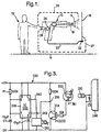
- a spraying device 10 held by user 12 produces a spray 14 of electrically charged droplets of for instance a paint formulation which, in normal operation, are drawn towards target 16.
- a spray 14 of electrically charged droplets of for instance a paint formulation which, in normal operation, are drawn towards target 16.
- Inherent in the nature of electrostatic spraying of liquid formulations is the need to form a circuit containing the applicator, the liquid spray cloud emerging from the nozzle 18 of the device 12 and the target substrate. This circuit must be formed to prevent an imbalance of charge between parts of the system and the consequent hazards of static discharge.
- a suitable electrostatic spraying technique for the "do-it-yourself" market is one in which charging of the liquid formulation does not rely on the generation of a corona discharge. Instead high voltage is applied to the liquid emerging at the nozzle of the spraying device (eg via a contact in the vicinity of the nozzle outlet or via the body of liquid) so as to establish an intense electric field relative to the target to be sprayed in such a way that the electrostatic forces assist in drawing the emerging liquid into a ligament which is of a diameter substantially less than that of the nozzle outlet and which thereafter breaks up into electrically charged droplets.
- This spraying technique involves a very efficient charging process and corona discharges, in normal operation, are virtually non-existent.
- the primary charge return path serves to prevent the development of a charge imbalance between the device and the target.
- the target and/or the device is connected to earth, eg indirectly via the user in the case of the device and, in the case of the device, there may be a path to earth via any supporting structure between the target and earth.
- the path to earth may be via the vehicle wheels/tyres and more particularly via dirt, gnme etc adhenng to the wheels.
- the connection to earth Is not essential and, in any event, may not be reliably established under all circumstances. More important is that a primary charge return path is established between the device 10 and the target 16 so as to maintain charge balance.
- the primary charge return path is established by means of an electncally conductive lead 20 connected at one end to the device and, at the other end, to the target substrate 16 via a suitable clip 22 which is designed to "bite" into the target substrate, eg a crocodile-type clip.
- Typical situations may include:
- Such problems can be avoided by the provision of a detector 24 for detecting charge return to the device via paths other than the pnmary path 20. For instance in the case of an inadequate connection being made with the substrate, if spraying continues, the build up of charge on the substrate 16 will result in a tendency for further charge to be repelled. Such charge will consequently seek targets other than the intended target, one such target being the user 12.
- an alternative charge return path is via sprayback (initially very small amounts) depositing on the user - this secondary return path is indicated by broken line 26 in Figure 1 and is in parallel with the primary return path.
- Another secondary charge return mechanism would be via the ground (broken line 27) and a further mechanism may be charge resulting from stray corona effects which can occur at the nozzle when spraying is affected by the loss of an effective primary charge return path and, in this event, the charge resulting from stray corona may again return to the device via the user 12.
- the detector 24 is provided in the secondary charge return path including the user 12 and is connected to the user via a contact pad 28 located on the device in a position for contact with the user's hand, eg the contact pad may be provided on. or form at least pan of, a hand grip portion of the device. If the integnty of the primary return path is either not established in the first place or is disturbed during spraying, it will be understood that charge return to the device will increasingly take place via the secondary route or routes.
- the detector 24 monitors the return of charge via the secondary route(s) and may be arranged to produce a suitable signal, such as a repeated audible bleep (which may increase in amplitude as the level of charge imbalance increases), to warn the user that an inadequate pnmary charge return circuit has been made. In this way, the user is given the opportunity to remedy the defect and. if unsuccessful, to abandon spraying that particular target because of its unsuitability.
- a suitable signal such as a repeated audible bleep (which may increase in amplitude as the level of charge imbalance increases)
- Establishing a secondary charge return path via the user is a convenient way of detecting charge return to the device via routes other than the primary charge return path afforded by the conductive lead 20.
- the device may be provided with a charge collection zone (not shown) at a suitable location, eg an exposed surface of the device on to which charge/droplet deposition will tend to occur sprayback or stray corona is produced as a result of a faulty primary charge return path.
- the detector 24 will then be connected to the charge collection zone so that charge return via this route can be monitored.
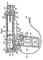
- the spray gun of Figure 2 is intended for hand-held use and is suitable for use in spraying relatively viscous, low resistivity liquid formulations such as paints, at flow rates of up to at least 4 cc/min.
- a typical formulation to be sprayed has a viscosity of the order of 0.1 Pa.s (1 Poise) and a resistivity of the order of 5 x 10 6 ohm.cm.
- the spray gun comprises a body member 202 and a hand grip 204.
- the body member 202 is in the form of a tube of insulating plastics material, eg a highly insulating material such as polypropylene.
- the hand gnp 204 may, at least in part, also be of highly insulating material such as polypropylene.
- the body member is provided with a collar 206 which is also composed of a highly insulating material such as polypropylene and which is screwthreadedly or otherwise releasably engaged with the body member 202 for quick release and access to the liquid container.
- the collar 206 secures a component 208 In position at the end of the body member 202, the component 208 comprising a base 210 and an integral annular shroud 212 which projects forwardly of the gun.
- the base 210 has a central aperture through which a nozzle 214 projects, the rear end of the nozzle 214 being formed with flange 215 which seats against the rear face of the base 210.
- the nozzle 214 is composed of a highly insulating material, such as a polyacetal (eg "Delrin”), typically with a bulk resistivity of the order of 10 15 ohm.cm.
- the body member 202 receives a replaceable cartridge 216 for delivering liquid to be sprayed to the nozzle 214.
- a positive feed of liquid to the nozzle 214 is needed and in this embodiment of the invention is effected by the use a cartridge in the form of a so-called bamer pack compnsing a metal container 218 pressurised by a liquefied propellant, eg fluorocarbon 134A, and the liquid to be sprayed is enclosed within a flexible metal foil sack 220 which separates the liquid from the propellant.
- a liquefied propellant eg fluorocarbon 134A
- the intenor of the sack 220 communicates with an axial passage 222 within the nozzle via a valve 224 which operates in a similar manner to the valve of a conventional aerosol-type can in that displacement of the valve in the rearward direction relative to the container 218 opens the valve 224 to permit positive liquid flow into the passage 222 (by virtue of the pressurisation produced by the propellant).
- the passage 222 terminates at its forward end in a reduced diameter bore forming the outlet of the nozzle.
- the forward extremity of the nozzle 214 terminates close to or at a plane containing the forward extremity of the shroud 212.
- the body member 202 accommodates a high voltage generator 226 which is mounted in a tubular carner 228.
- the carrier 228 is mounted for limited sliding movement axially of the body member 202.
- a tension spring 230 biases the carrier 228 rearwardly.
- the high voltage generator 226 is of the type which produces a pulsed output and then rectifies and smooths it to provide a high voltage DC output.
- a suitable form of generator 226 of this type is descnbed in European Patent Application No. 163390.
- the generator has a high voltage output pole 232 connected by lead 233 to a contact 234 secured to the carner and arranged for engagement with the rear end of the metal container 218.
- a second output pole 235 of the generator is arranged to be connected to earth, inter alia via lead 236 and a contact strip 240.
- the contact strip 240 forms part of the hand grip 204 and is composed of a dissipative material. ie one which has some conductivity but provides a resistance (typically of the order of 10 7 to 10 10 ohm cm) for reasons explained in our pnor European Patent Application No. 503766 .
- a suitable matenal is Beetle GB8 polyester available from British Industrial Plastics. In this way, when the gun is held by the user, a path to earth can be established through the user.
- the generator is powered by a low voltage DC supply comprising battery pack 242 accommodated within the handgrip 204 and forming part of a low voltage circuit including lead 236 coupled to earth (via the pad 240 and the user) and a lead 244 connecting the battery pack 242 to the input side of the generator 226 via a microswitch 246.
- the valve 224 is opened, in use, by relative movement between the cartridge 216 and the body member 202, the nozzle 214 remaining fixed relative to the body member. Movement to operate the valve 224 is applied to the cartridge 216 by movement of the generator/carrier assembly, the latter being moved by operation of a trigger 248 associated with the handgrip 204 and which, when squeezed, pivots lever 250 about its pivotal connection 252 thereby pivoting a further lever 254 which is pivoted at 256 and is coupled to lever 250 by link 258.
- the lever 254 bears against the rear end of the carrier 228 so that pivoting of the lever 254 is effective to displace the carrier and hence the cartridge 216 forwardly thereby opening the valve 224.
- the high voltage produced by the generator is coupled to the outlet of the nozzle 214 via contact 234, the metal container 218 and the liquid within the passage 222 to provide an electric field between the nozzle tip and the surroundings at earth potential.
- This electric field is established with the aim of drawing the liquid emerging at the nozzle outlet into a ligament which will break up into a divergent spray of relatively uniformly-sized, electrically charged droplets suitable for deposition as a uniform film.
- the diameter of the outlet has to be made relatively large (typically at least 600 microns) in order to achieve flow rates up to at least 4 cc/min.
- relatively viscous materials to achieve satisfactory ligament formation (especially single, axially directed ligament formation) at flow rates of this order, it is necessary to operate at higher voltages than are necessary for lower viscosity liquids since ligament formation from viscous materials requires increased electric field intensity.
- the generator 226 employed has an output voltage of 25 kV or greater as measured by connecting the high voltage output of the generator to a Brandenburg 139D high voltage meter having an internal resistance of 30 Gigohm.
- the use of voltages of this order would normally lead to spurious spraying probably as a result of corona discharge effects since the field intensity in the immediate vicinity of the nozzle outlet may exceed the breakdown potential of air.
- Such spunous spraying may for instance result in highly polydisperse droplets in the form of a mist of very fine droplets splitting off from the ligament and poorly divergent, paraxial streams of coarse droplets.
- the component 208 is composed of a semi-insulating material (typically with a bulk resistivity up to 10 11 - 10 12 ohm.cm), eg "Hytrel" grade 4778 available from DuPont Corporation, and is arranged with a rearwardly projecting annular portion 262 thereof in contact with the metal container 218 so that the voltage applied via the contact 234 Is established at the forward extremity of the shroud 212 and is of the same polarity as, and of substantially the same magnitude as, the voltage produced at the outlet of the nozzle 214.
- a semi-insulating material typically with a bulk resistivity up to 10 11 - 10 12 ohm.cm
- Hytrel grade 4778
- the annular portion 262 is trapped between the forward end of the body member 202 and a flange 264 on collar 206 so that component 208 is fixed relative to the body member 202. Operation of the trigger 248 leads to displacement of the container 218 relative to the component 208 but electrical continuity is maintained by sliding contact between the leading end of the container 218 and the inner periphery of the annular portion 262.
- contact between the high voltage generator and the shroud may be effected in ways other than the sliding contact arrangement shown; for instance the contact may be made through a spring contact.
- the contact arrangement will be such as to ensure that a voltage substantially corresponding to that established at the nozzle tip is developed on the shroud in advance of, or substantially simultaneous with the commencement of spraying so that the shroud is immediately effective on commencement of spraying.
- the field intensity in the immediate vicinity of the nozzle tip can be attenuated sufficiently to produce formation of a single ligament which breaks up into relatively uniform-sized droplets.
- the optimum position of the shroud extremity can be readily established by trial and error, ie by means of a prototype version of the gun having an axially adjustable shroud. In this way, the shroud can be adjusted forwardly from a retracted position while observing the nature of the spray. Initially, with the shroud retracted, the spunous spraying effects referred to above are observed and as the shroud is moved forwardly a position is reached where the spray quality improves markedly and relatively uniform-sized droplets are obtained.
- the arrangement will be such that the angle between imaginary lines extending between the forward extremity of the nozzle and diametrically opposite forward extremities of the shroud is in the range 140 to 195°, more preferably 150 to 180° (angles less than 180° corresponding to the nozzle forward extremity being forward of the shroud and angles greater than 180° corresponding to the shroud being forward of the nozzle forward extremity).
- ligament break up can be demonstrated by operating two nozzles under identical conditions with the same liquid, one nozzle being operated without a shroud and the other with a shroud located at an optimum position.
- a typical break up regime in the case where no shroud is present involves the production of a mist of very fine droplets a short distance from the nozzle outlet followed by break up of the central core of the ligament into streams of poorly divergent coarse droplets.
- the spray produced in this instance is wholly unsuitable for the production of a uniform film of the liquid (eg paint) on a surface to be sprayed.
- the presence of the metal container 218, coupled with the relatively high voltage applied at the tip of the nozzle (ie usually greater than 25 kV). can lead to a large build up of capacitively stored charge during spraying with the possibility of the user experiencing an unpleasant electric shock if the user attempts to access the intenor of the device on cessation of spraying, eg for the purpose of replacing the cartridge.
- This possibility may be obviated by the incorporation of means for discharging the capacitively stored charge in response to cessation of spraying, such means being disclosed in published international Application No. WO-A-94/13063.
- the spray gun illustrated in Figure 2 is particularly suitable for spraying liquids having viscosities between 0.05 and 1 Pa.s (0.5 and 10 Poise), especially 0.1 to 0.8 Pa.s (1 to 8 Poise) and resistivities between 5 ⁇ 10 9 and 5 ⁇ 10 7 ohm.cm (especially between 2 ⁇ 10 6 and 1 ⁇ 10 7 ohm.cm) at spraying/flow rates of up to at least 4 cc/min and more preferably up to 6 cc/min.
- the diameter of the nozzle outlet and the voltage output of the voltage generator 226 are selected according to the viscosity and resistivity of the liquid to be sprayed. Typically the nozzle outlet-will have a diameter of at least 500 microns.
- the DC output voltage of the generator 226 will typically be between 25 and 40 kV, more usually between 28 and 35 kV, as measured by a Brandenburg 139D high voltage meter having an internal resistance of 30 Gigohm.
- FIG. 2 The embodiment of Figure 2 is adapted in accordance with the present Invention by the provision of a connector lead 300 terminating at one end in a plug 302 which is insertable into a socket 304 on the device and at the other ena in a crocodile-type clip 306 by means of which a good electrical contact can normally be established with the substrate to be sprayed.
- the stem 308 of the plug 302 is conductive but terminates in a non-conductive tip 310 which, on insertion into the socket, closes a spring-biased switch 312 connected in lead 244 and thereby controlling supply of power to the generator so that the latter can only be activated by means of trigger 248 when the plug 302 is correctly inserted.
- a current detection circuit 320 is connected to leads 322 and 324 associated with the low and high voltage terminals of the battery supply 242 and also to the pad 240.
- the circuit 320 which is described below in connection with Figure 3, serves to detect charge flow via the user and pad 240 (the secondary charge return path) in the event of an inadequate connection being made through the clip 306.
- the circuit 320 compnses a neon discharge lamp 330 connected between the user contact pad 240 and the low voltage side of the battery supply 242.
- a capacitor C5 is connected across the terminals of the lamp 330 to control charging and discharging of the lamp.
- charge return to the device via the user is insignificant.
- charge return takes place via the secondary path thereby developing a voltage across the neon lamp 330 which results in a discharge.
- the light emitted by the discharge is detected by a photosensitive Darlington pair 332 which in turn renders transistor 334 conductive causing a low voltage to be applied, via point 336, to a timer 338 (eg an IC 555 chip).
- the timer produces an output at 340 with a pulse length determined by of an RC network R1, C1 associated with the timer 338.
- the output 340 drives a piezoelectric sound generator 342 which serves to produce an audible "bleep". It will be understood that, while the imbalance condition prevails, the bleep will be produced repeatedly until the operator releases the trigger 248 and takes appropnate remedial action, eg ensunng good electrical contact is made between the clip and the substrate to be sprayed.
- the circuit arrangement may be such that the bleep produced increases in frequency and/or amplitude as the charge return via pad 240 increases.
- FIG 4 this illustrates an alternative embodiment of the invention in which the detection of satisfactory spraying conditions is determined by means of an impedance or resistance measuring circuit built into the spraying device.
- the device 400 may be substantially the same as that described in our prior Application No. WO 95/13879 and also in relation to Figure 2 herein and is provided with a lead 402 connected to the device and terminating in a connector 404 which is intended to establish an effective electrical connection to the target 406 to be sprayed.
- the lead 402 is connected to resistance or impedance measuring circuitry 408 incorporated in the device 400 which in turn has a terminal 410 located externally (but which may be stowed internally when not in use if desired).
- the terminal 410 is arranged in such a way that it can be readily brought into contact with the target to be sprayed, eg by appropriate manipulation of the device 400, so that a circuit can be completed througn through the target between the terminal 410 and the connector 404.
- the circuitry 408 can be operated to effect for example a dc resistance measurement and thereby determine whether a satisfactory primary charge return path is present. Operation of the circuitry 408 may be initiated by the user, eg by means of a suitably located test switch associated with the device 400 and arranged to connect the circuitry 408 to the low voltage supply housed within the device 400.
- the circuitry 408 may be arranged to produce a warning signal. eg visual and/or audible, in the event that the dc resistance measured is in excess of a predetermined threshold.
- the threshold is selected to provide a suitable safety margin and can be determined empirically.
- the terminal 410 is conveniently in the form of a pad or strip of deformable material having some degree of electrical conductivity, a resiliently deformable foam material for example whicn may be composed of a conductive or semi-conductive material or may be impregnated or filled with conductive or semi-conductive material. eg carbon particles.
- the terminal 410 is preferably located on the device at a point distant from the nozzle end and, as mentioned previously, will be located so that it can be readily brought into contact with the target. Thus, as shown in Figure 4, it is located on the rear end of the device 400 and can be pressed against the surface of the target by holding the handgnp the other way round so that the pad 410 is presented forwardly for contact with the target. Once the test has been carned out and a satisfactory result obtained, the device is reversed and spraying can then proceed.
Landscapes
- Chemical & Material Sciences (AREA)
- Analytical Chemistry (AREA)
- Electrostatic Spraying Apparatus (AREA)
- Catching Or Destruction (AREA)
- Reciprocating Pumps (AREA)
- Disintegrating Or Milling (AREA)
- Formation And Processing Of Food Products (AREA)
- Cyclones (AREA)
- Injection Moulding Of Plastics Or The Like (AREA)
- Chemical Or Physical Treatment Of Fibers (AREA)
- Polarising Elements (AREA)
Abstract
Description
where the operator is isolated from the target for example as a result of weanng highly insulating footwear.
Claims (24)
- An electrostatic spraying device (10) provided with contact means (20, 22) for establishing a primary charge return path (20) between an object (16) to be sprayed and the device characterised by a secondary charge return path (26, 27); and means (24) for monitoring charge return to the device via the secondary charge return path during spraying operation of the device.
- A device as claimed in Claim 1 in which said monitoring means is arranged to produce an output signal in the event of an inadequate connection to the object being sprayed.
- A device as claimed in Claim 1 in which said monitoring means is arranged to produce an output signal in the event that charge return via the secondary charge return path occurs or is in an amount exceeding a predetermined value.
- A device as claimed in any one of Claims 1-3 in which the secondary charge return path is via an operator holding the device.
- A device as claimed in any one of Claims 1-4 in which the contact means for providing the primary charge return path includes an electrical conductor in the form of a lead (20) terminating in a connector (22) for connection to a convenient site on the object to be sprayed.
- A device as claimed in any one of Claims 1-5 in which the arrangement is such that, if the contact means is not connected to the device either at all or correctly, spraying operation is disabled.
- A device as claimed in any one of Claims 1-5 in which the contact means is permanently connected to the device.
- A device as claimed in any one of Claims 2-7 in which the output signal produced is of a visual, audible and/or tactile character.
- A device as claimed in any one of the preceding claims in which means is provided for suppressing spraying operation of the device in the event that potentially hazardous spraying conditions prevail.
- A device as claimed in any one of Claims 2-9 in which said output signal is indicative of conditions in which continued spraying is potentially hazardous.
- A device as claimed in any one of the preceding claims in which the charge monitoring means comprises an arrangement in which charge is stored (C5) until a threshold potential is attained whereupon emission of radiation occurs, the radiation being arranged to fall on a radiation-sensitive switch (332) which operates to produce an output signal.
- A device as claimed in any one of the preceding claims in which the device is of the type designed for hand-held use and the secondary path includes a terminal portion (28) provided on a housing of the device at a location where it will come into contact with the user's hand during use of the device.
- A device as claimed in Claim 12 in which the terminal portion is made of a semi-conducting material.
- A device as claimed in Claim 12 or 13 comprising a portable unit suitable for hand-held use and having a nozzle (214) from which liquid to be sprayed is discharged, means (202, 216) for feeding the liquid to the nozzle and circuitry (226) for generating high voltage for application to the liquid.
- A device as claimed in Claim 14 which additionally comprises an electrode (212) located adjacent the nozzle to modify the field intensity in the vicinity of the outlet of the nozzle, means (218, 234) for electrically connecting the electrode to said high voltage generator to develop on the electrode a potential of the same polarity as the liquid emerging from the nozzle outlet and of a magnitude such that the potential gradient is reduced in the immediate vicinity of the outlet of the nozzle means.
- A device as claimed in Claim 14 or 15 comprising a housing (202) having a hand grip portion (204), means (220) for containing liquid to be sprayed, means (226) for producing from a low voltage source (242) a high voltage for application to liquid emerging from the nozzle, an electrically conductive lead (300) for establishing the primary charge return path between the object to be sprayed and the device, the lead terminating in the connector (306) for connection to the object, means (240) associated with the hand grip portion for establishing via the operator the secondary charge return path via which charge can return to the device when the primary path is inadequate to prevent build up of a charge imbalance between the object and the device, and means (320) responsive to charge return via the secondary path for producing the output signal indicative of conditions in which continued spraying is potentially hazardous.
- A device as claimed in Claim 16, suitable for use in spraying liquids having resistivities of the order of 5 x 10⁶ ohm.cm and viscosities of the order of 0.1 Pa.s (1 Poise) at a spraying rate up to at least 4 cc/min, said device comprising a high voltage generator (226), means (234) coupled to the high voltage generator for applying a potential to the liquid emerging at the outlet of the nozzle means (214), an electrode (212) located adjacent the nozzle means to modify the field intensity in the vicinity of the outlet of the nozzle means, first means (300) for establishing a primary charge return path from an object to be sprayed to the device; second means (240) for establishing a secondary charge return path; and means (320) for monitoring charge returned via the secondary path.
- A device as claimed in Claim 15 or 17 in which the electrode comprises a semi-insulating material.
- A device as claimed in any one of the preceding claims in which said monitoring means is constituted by means (408) for determining the resistance or impedance of the circuit so established.
- A method of electrostatically spraying a flowable material on to a target (16, 406) using a device (10, 202, 400) as claimed in any one of the preceding claims.
- A method of electrostatically spraying a flowable material on to a target (16, 406) by means of an electrostatic spraying device (10, 202, 400) comprising securing a contact means (22, 306, 404) to the target to establish a primary charge return path (20, 300, 402) between the target and the device characterised by monitoring charge return to the device via a secondary charge return path (24, 320, 408) during spraying operation of the device.
- A method as claimed in Claim 21 comprising monitoring charge return to the device via the secondary charge return path and producing an output signal in the event that charge return is indicative of an inadequate connection to the target.
- A method as claimed in Claim 21 comprising monitoring charge return to the device via the secondary charge return path and producing an output signal in the event that charge return via the secondary charge return path occurs or is in an amount exceeding a predetermined value.
- A method of electrostatically spraying a flowable material on to a target (16, 406) by means of an electrostatic spraying device (10, 202, 400) comprising establishing a primary charge return path (20, 300, 402) between the target and the device by securing a contact means (22, 306, 404) to the target, characterised by establishing a circuit including the target and the connection between the target and the primary charge return path, testing the resistance or impedance of that circuit, and proceeding with spraying if the resistance or impedance is determined to be compatible with an adequate connection with the target.
Applications Claiming Priority (3)
| Application Number | Priority Date | Filing Date | Title |
|---|---|---|---|
| GB9409167 | 1994-05-09 | ||
| GB9409167A GB9409167D0 (en) | 1994-05-09 | 1994-05-09 | Spraying devices |
| PCT/GB1995/000972 WO1995030489A1 (en) | 1994-05-09 | 1995-04-28 | Spraying devices |
Publications (2)
| Publication Number | Publication Date |
|---|---|
| EP0748257A1 EP0748257A1 (en) | 1996-12-18 |
| EP0748257B1 true EP0748257B1 (en) | 2002-09-11 |
Family
ID=10754779
Family Applications (1)
| Application Number | Title | Priority Date | Filing Date |
|---|---|---|---|
| EP95916790A Expired - Lifetime EP0748257B1 (en) | 1994-05-09 | 1995-04-28 | Spraying devices |
Country Status (17)
| Country | Link |
|---|---|
| US (1) | US5932011A (en) |
| EP (1) | EP0748257B1 (en) |
| JP (1) | JP3840531B2 (en) |
| KR (1) | KR100376242B1 (en) |
| CN (1) | CN1071145C (en) |
| AT (1) | ATE223760T1 (en) |
| AU (1) | AU708479B2 (en) |
| CA (1) | CA2187742C (en) |
| DE (1) | DE69528159T2 (en) |
| DK (1) | DK0748257T3 (en) |
| ES (1) | ES2180630T3 (en) |
| GB (1) | GB9409167D0 (en) |
| HK (1) | HK1011306A1 (en) |
| PT (1) | PT748257E (en) |
| TW (1) | TW315319B (en) |
| WO (1) | WO1995030489A1 (en) |
| ZA (1) | ZA953611B (en) |
Families Citing this family (26)
| Publication number | Priority date | Publication date | Assignee | Title |
|---|---|---|---|---|
| DE19650781A1 (en) * | 1996-12-06 | 1998-06-10 | Itw Oberflaechentechnik Gmbh | Spray coating device |
| US20030205631A1 (en) * | 2000-05-25 | 2003-11-06 | The Procter & Gamble Company | Spraying of liquids |
| US6564154B1 (en) | 2000-11-28 | 2003-05-13 | Steelcase Development Corporation | Monitoring system |
| DE10150636C2 (en) * | 2001-10-12 | 2003-08-21 | Diehl Munitionssysteme Gmbh | High-voltage generator, in particular for use as an interference frequency generator |
| US7849850B2 (en) * | 2003-02-28 | 2010-12-14 | Battelle Memorial Institute | Nozzle for handheld pulmonary aerosol delivery device |
| DE102004036230A1 (en) * | 2003-08-01 | 2005-03-03 | Kansai Paint Co., Ltd., Amagasaki | Coating device and coating method |
| JP2005313143A (en) * | 2004-03-29 | 2005-11-10 | Japan Organo Co Ltd | Method and apparatus for manufacturing marine ballast water |
| EP1797962B1 (en) * | 2004-08-10 | 2012-06-06 | Abb K.K. | Electrostatic coating apparatus |
| CA2598990A1 (en) * | 2005-02-25 | 2006-08-31 | Battelle Memorial Institute | Spray indication |
| US20070059965A1 (en) * | 2005-09-13 | 2007-03-15 | Magna International Inc. | Method and apparatus for non-contact grounding detection in an electrostatic paint system |
| US7732737B2 (en) * | 2005-10-11 | 2010-06-08 | Kimberly-Clark Worldwide, Inc. | Micro powered warming container |
| US7665460B2 (en) * | 2005-10-11 | 2010-02-23 | Kimberly-Clark Worldwide, Inc. | Micro powered gas-forming device |
| US7661562B2 (en) * | 2005-10-11 | 2010-02-16 | Kimberly-Clark Worldwide, Inc. | Micro powered dispensing device |
| US7774894B2 (en) * | 2005-10-11 | 2010-08-17 | Kimberly-Clark Worldwide, Inc. | Micro powered floor cleaning device |
| WO2007094835A1 (en) | 2006-02-14 | 2007-08-23 | Ventaira Pharmaceuticals, Inc. | Dissociated discharge ehd sprayer with electric field shield |
| US8534301B2 (en) | 2008-06-02 | 2013-09-17 | Innovation Direct Llc | Steam mop |
| CN101963633A (en) * | 2009-07-24 | 2011-02-02 | 沈为国 | Spraying electrified state detector for electrostatic sprayer |
| US8893990B2 (en) * | 2010-02-26 | 2014-11-25 | Finishing Brands Holdings Inc. | Electrostatic spray system |
| US8833679B2 (en) | 2010-11-24 | 2014-09-16 | Finishing Brands Holdings, Inc. | Electrostatic spray system with grounding teeth |
| WO2012097360A2 (en) * | 2011-01-14 | 2012-07-19 | Graco Minnesota Inc. | Electrostatic discharge control and isolation system for spraying sytems |
| JP5894021B2 (en) * | 2012-06-26 | 2016-03-23 | 旭サナック株式会社 | Charge amount measurement method for spray droplets, charge amount measurement device, and charge amount control device for spray droplets using them |
| EP3188843B2 (en) | 2014-09-04 | 2023-10-04 | Octet Medical, Inc. | Electrostatic fluid delivery system |
| JP6452833B2 (en) | 2015-02-04 | 2019-01-16 | ボストン サイエンティフィック ニューロモデュレイション コーポレイション | Method and apparatus for programming charge recovery in a neural stimulation waveform |
| TWM518745U (en) * | 2015-10-30 | 2016-03-11 | Marketech Int Corp | Internal electrostatic reduction control valve for organic solvent delivery pipe |
| EP3799962A1 (en) | 2015-12-21 | 2021-04-07 | Victory Innovations Company | Electrostatic fluid delivery backpack system |
| WO2024030666A1 (en) * | 2022-08-05 | 2024-02-08 | FouRy, Inc. | Systems and methods for an electrostatic atomizer of moderately conductive fluids |
Family Cites Families (14)
| Publication number | Priority date | Publication date | Assignee | Title |
|---|---|---|---|---|
| US3894272A (en) * | 1974-01-14 | 1975-07-08 | Ransburg Corp | Method and apparatus for determining incipient grounding of a high voltage electrostatic system |
| US3851618A (en) * | 1974-01-14 | 1974-12-03 | Ransburg Corp | Electrostatic coating apparatus |
| SU736435A1 (en) * | 1978-07-14 | 1986-06-30 | Предприятие П/Я В-2346 | Device for applying powder materials in electric field |
| IT1137200B (en) * | 1980-07-10 | 1986-09-03 | Roederstein Ernst Spezialfabri | MANUAL APPLIANCE FOR THE ELECTROSTATIC FLOCKING OF OBJECTS |
| DE3207402C2 (en) * | 1982-03-02 | 1985-04-25 | Robert Bosch Gmbh, 7000 Stuttgart | Procedure for monitoring a powder coating system against the risk of explosion |
| GB2130123A (en) * | 1982-11-04 | 1984-05-31 | Ici Plc | Malfunction detector for electrostatic spraying apparatus |
| US4682735A (en) * | 1983-06-29 | 1987-07-28 | Graco Inc. | Electrostatic field indicator light for electrostatic nozzles |
| FR2551928B1 (en) * | 1983-09-14 | 1986-05-23 | Sames Sa | PROTECTION DEVICE FOR LOW-VOLTAGE CIRCUITS OF ELECTROSTATIC PROJECTION EQUIPMENT, AND PROJECTION EQUIPMENT INCORPORATING THIS DEVICE |
| JP2532001B2 (en) * | 1990-07-24 | 1996-09-11 | 本田技研工業株式会社 | Ground check method in electrostatic coating of defective conductors |
| JPH0757330B2 (en) * | 1990-10-23 | 1995-06-21 | 旭サナック株式会社 | Spark prevention device in electrostatic coating equipment |
| US5138513A (en) * | 1991-01-23 | 1992-08-11 | Ransburg Corporation | Arc preventing electrostatic power supply |
| GB9105327D0 (en) * | 1991-03-13 | 1991-04-24 | Ici Plc | Electrostatic spraying of liquids |
| JPH07501972A (en) * | 1991-08-13 | 1995-03-02 | ザ・モーガン・クルーシブル・カンパニー・ピーエルシー | spray gun |
| US5397605A (en) * | 1992-05-29 | 1995-03-14 | Barbieri; Girolamo | Method and apparatus for electrostatically coating a workpiece with paint |
-
1994
- 1994-05-09 GB GB9409167A patent/GB9409167D0/en active Pending
-
1995
- 1995-04-28 CA CA002187742A patent/CA2187742C/en not_active Expired - Fee Related
- 1995-04-28 ES ES95916790T patent/ES2180630T3/en not_active Expired - Lifetime
- 1995-04-28 EP EP95916790A patent/EP0748257B1/en not_active Expired - Lifetime
- 1995-04-28 PT PT95916790T patent/PT748257E/en unknown
- 1995-04-28 WO PCT/GB1995/000972 patent/WO1995030489A1/en active IP Right Grant
- 1995-04-28 KR KR1019960706359A patent/KR100376242B1/en not_active IP Right Cessation
- 1995-04-28 DK DK95916790T patent/DK0748257T3/en active
- 1995-04-28 CN CN95192991A patent/CN1071145C/en not_active Expired - Fee Related
- 1995-04-28 JP JP52875595A patent/JP3840531B2/en not_active Expired - Fee Related
- 1995-04-28 DE DE69528159T patent/DE69528159T2/en not_active Expired - Fee Related
- 1995-04-28 AT AT95916790T patent/ATE223760T1/en not_active IP Right Cessation
- 1995-04-28 AU AU23156/95A patent/AU708479B2/en not_active Ceased
- 1995-04-28 US US08/732,431 patent/US5932011A/en not_active Expired - Lifetime
- 1995-05-03 TW TW084104432A patent/TW315319B/zh active
- 1995-05-04 ZA ZA953611A patent/ZA953611B/en unknown
-
1998
- 1998-11-27 HK HK98112411A patent/HK1011306A1/en not_active IP Right Cessation
Also Published As
| Publication number | Publication date |
|---|---|
| CA2187742A1 (en) | 1995-11-16 |
| TW315319B (en) | 1997-09-11 |
| JPH09512744A (en) | 1997-12-22 |
| ZA953611B (en) | 1995-11-09 |
| US5932011A (en) | 1999-08-03 |
| DE69528159D1 (en) | 2002-10-17 |
| DK0748257T3 (en) | 2003-01-13 |
| JP3840531B2 (en) | 2006-11-01 |
| CA2187742C (en) | 2003-12-09 |
| KR100376242B1 (en) | 2003-06-11 |
| CN1071145C (en) | 2001-09-19 |
| PT748257E (en) | 2003-01-31 |
| WO1995030489A1 (en) | 1995-11-16 |
| AU708479B2 (en) | 1999-08-05 |
| DE69528159T2 (en) | 2003-06-05 |
| ATE223760T1 (en) | 2002-09-15 |
| CN1147776A (en) | 1997-04-16 |
| EP0748257A1 (en) | 1996-12-18 |
| HK1011306A1 (en) | 1999-07-09 |
| ES2180630T3 (en) | 2003-02-16 |
| AU2315695A (en) | 1995-11-29 |
| GB9409167D0 (en) | 1994-06-29 |
Similar Documents
| Publication | Publication Date | Title |
|---|---|---|
| EP0748257B1 (en) | Spraying devices | |
| CA2179964C (en) | Electrostatic spray appliance for coating material | |
| US5222664A (en) | Hand-held electrostatic spraying device adapted for shock suppression and method | |
| US4561037A (en) | Electrostatic spraying | |
| JP3384811B2 (en) | Electrostatic spray device, method of using electrostatic spray device, and electrostatic spray method | |
| US4659012A (en) | Electrostatic spraying process and apparatus | |
| KR100229943B1 (en) | Spraying of liquids | |
| US4358059A (en) | Electrostatic spraying | |
| EP0186353B1 (en) | Spraying apparatus | |
| AU704237B2 (en) | Spraying device | |
| US9085001B2 (en) | Electrostatic coating system, spray gun for electrostatic coating, and alternating power source unit | |
| CS239924B2 (en) | Holder of vessel for electrostatically sprayed liquid | |
| US4186886A (en) | Adapting means providing detachable mounting of an induction-charging adapter head on a spray device | |
| JPH09502647A (en) | Spray induction charging device | |
| PT678337E (en) | PULVERIZATION DEVICE FOR A LIQUID OPHTHALMIC FORMULA | |
| JPH02503529A (en) | Electrostatic spray gun equipment and cable assembly | |
| EP0179593B1 (en) | Airless spray gun having tip discharge resistance | |
| JP3545030B2 (en) | Electrostatic powder spray gun with hose purification adapter | |
| US6423143B1 (en) | Voltage block monitoring system | |
| EP0132062B1 (en) | Electrostatic spraying | |
| JP3335937B2 (en) | High voltage control method for electrostatic coating | |
| GB2093732A (en) | Spraying system | |
| DK152894B (en) | Demountable container for electrostatic spraying |
Legal Events
| Date | Code | Title | Description |
|---|---|---|---|
| PUAI | Public reference made under article 153(3) epc to a published international application that has entered the european phase |
Free format text: ORIGINAL CODE: 0009012 |
|
| 17P | Request for examination filed |
Effective date: 19961002 |
|
| AK | Designated contracting states |
Kind code of ref document: A1 Designated state(s): AT BE CH DE DK ES FR GB GR IE IT LI LU MC NL PT SE |
|
| RAP1 | Party data changed (applicant data changed or rights of an application transferred) |
Owner name: THE PROCTER & GAMBLE COMPANY |
|
| 17Q | First examination report despatched |
Effective date: 20000207 |
|
| GRAG | Despatch of communication of intention to grant |
Free format text: ORIGINAL CODE: EPIDOS AGRA |
|
| GRAG | Despatch of communication of intention to grant |
Free format text: ORIGINAL CODE: EPIDOS AGRA |
|
| GRAH | Despatch of communication of intention to grant a patent |
Free format text: ORIGINAL CODE: EPIDOS IGRA |
|
| GRAG | Despatch of communication of intention to grant |
Free format text: ORIGINAL CODE: EPIDOS AGRA |
|
| GRAH | Despatch of communication of intention to grant a patent |
Free format text: ORIGINAL CODE: EPIDOS IGRA |
|
| GRAG | Despatch of communication of intention to grant |
Free format text: ORIGINAL CODE: EPIDOS AGRA |
|
| GRAH | Despatch of communication of intention to grant a patent |
Free format text: ORIGINAL CODE: EPIDOS IGRA |
|
| GRAH | Despatch of communication of intention to grant a patent |
Free format text: ORIGINAL CODE: EPIDOS IGRA |
|
| GRAA | (expected) grant |
Free format text: ORIGINAL CODE: 0009210 |
|
| AK | Designated contracting states |
Kind code of ref document: B1 Designated state(s): AT BE CH DE DK ES FR GB GR IE IT LI LU MC NL PT SE |
|
| REF | Corresponds to: |
Ref document number: 223760 Country of ref document: AT Date of ref document: 20020915 Kind code of ref document: T |
|
| REG | Reference to a national code |
Ref country code: GB Ref legal event code: FG4D |
|
| REG | Reference to a national code |
Ref country code: CH Ref legal event code: NV Representative=s name: RITSCHER & PARTNER AG PATENTANWAELTE Ref country code: CH Ref legal event code: EP |
|
| REG | Reference to a national code |
Ref country code: IE Ref legal event code: FG4D |
|
| REF | Corresponds to: |
Ref document number: 69528159 Country of ref document: DE Date of ref document: 20021017 |
|
| REG | Reference to a national code |
Ref country code: GR Ref legal event code: EP Ref document number: 20020403770 Country of ref document: GR |
|
| REG | Reference to a national code |
Ref country code: DK Ref legal event code: T3 |
|
| REG | Reference to a national code |
Ref country code: PT Ref legal event code: SC4A Free format text: AVAILABILITY OF NATIONAL TRANSLATION Effective date: 20021210 |
|
| REG | Reference to a national code |
Ref country code: ES Ref legal event code: FG2A Ref document number: 2180630 Country of ref document: ES Kind code of ref document: T3 |
|
| ET | Fr: translation filed | ||
| PG25 | Lapsed in a contracting state [announced via postgrant information from national office to epo] |
Ref country code: MC Free format text: LAPSE BECAUSE OF NON-PAYMENT OF DUE FEES Effective date: 20030430 |
|
| PLBE | No opposition filed within time limit |
Free format text: ORIGINAL CODE: 0009261 |
|
| STAA | Information on the status of an ep patent application or granted ep patent |
Free format text: STATUS: NO OPPOSITION FILED WITHIN TIME LIMIT |
|
| 26N | No opposition filed |
Effective date: 20030612 |
|
| PGFP | Annual fee paid to national office [announced via postgrant information from national office to epo] |
Ref country code: DK Payment date: 20050314 Year of fee payment: 11 Ref country code: AT Payment date: 20050314 Year of fee payment: 11 |
|
| PGFP | Annual fee paid to national office [announced via postgrant information from national office to epo] |
Ref country code: SE Payment date: 20050404 Year of fee payment: 11 |
|
| PGFP | Annual fee paid to national office [announced via postgrant information from national office to epo] |
Ref country code: PT Payment date: 20050406 Year of fee payment: 11 |
|
| PGFP | Annual fee paid to national office [announced via postgrant information from national office to epo] |
Ref country code: IE Payment date: 20050414 Year of fee payment: 11 |
|
| PGFP | Annual fee paid to national office [announced via postgrant information from national office to epo] |
Ref country code: GR Payment date: 20050421 Year of fee payment: 11 |
|
| PGFP | Annual fee paid to national office [announced via postgrant information from national office to epo] |
Ref country code: BE Payment date: 20050428 Year of fee payment: 11 |
|
| PGFP | Annual fee paid to national office [announced via postgrant information from national office to epo] |
Ref country code: LU Payment date: 20050603 Year of fee payment: 11 |
|
| PGFP | Annual fee paid to national office [announced via postgrant information from national office to epo] |
Ref country code: CH Payment date: 20050613 Year of fee payment: 11 |
|
| PGFP | Annual fee paid to national office [announced via postgrant information from national office to epo] |
Ref country code: NL Payment date: 20060324 Year of fee payment: 12 |
|
| PG25 | Lapsed in a contracting state [announced via postgrant information from national office to epo] |
Ref country code: IE Free format text: LAPSE BECAUSE OF NON-PAYMENT OF DUE FEES Effective date: 20060428 Ref country code: AT Free format text: LAPSE BECAUSE OF NON-PAYMENT OF DUE FEES Effective date: 20060428 |
|
| PG25 | Lapsed in a contracting state [announced via postgrant information from national office to epo] |
Ref country code: SE Free format text: LAPSE BECAUSE OF NON-PAYMENT OF DUE FEES Effective date: 20060429 |
|
| PG25 | Lapsed in a contracting state [announced via postgrant information from national office to epo] |
Ref country code: LU Free format text: LAPSE BECAUSE OF NON-PAYMENT OF DUE FEES Effective date: 20060430 Ref country code: LI Free format text: LAPSE BECAUSE OF NON-PAYMENT OF DUE FEES Effective date: 20060430 Ref country code: CH Free format text: LAPSE BECAUSE OF NON-PAYMENT OF DUE FEES Effective date: 20060430 Ref country code: BE Free format text: LAPSE BECAUSE OF NON-PAYMENT OF DUE FEES Effective date: 20060430 |
|
| PG25 | Lapsed in a contracting state [announced via postgrant information from national office to epo] |
Ref country code: DK Free format text: LAPSE BECAUSE OF NON-PAYMENT OF DUE FEES Effective date: 20060501 |
|
| PG25 | Lapsed in a contracting state [announced via postgrant information from national office to epo] |
Ref country code: PT Free format text: LAPSE BECAUSE OF NON-PAYMENT OF DUE FEES Effective date: 20061030 |
|
| REG | Reference to a national code |
Ref country code: DK Ref legal event code: EBP |
|
| REG | Reference to a national code |
Ref country code: CH Ref legal event code: PL |
|
| EUG | Se: european patent has lapsed | ||
| REG | Reference to a national code |
Ref country code: PT Ref legal event code: MM4A Free format text: LAPSE DUE TO NON-PAYMENT OF FEES Effective date: 20061030 |
|
| REG | Reference to a national code |
Ref country code: IE Ref legal event code: MM4A |
|
| BERE | Be: lapsed |
Owner name: THE *PROCTER & GAMBLE CY Effective date: 20060430 |
|
| NLV4 | Nl: lapsed or anulled due to non-payment of the annual fee |
Effective date: 20071101 |
|
| PG25 | Lapsed in a contracting state [announced via postgrant information from national office to epo] |
Ref country code: NL Free format text: LAPSE BECAUSE OF NON-PAYMENT OF DUE FEES Effective date: 20071101 |
|
| PG25 | Lapsed in a contracting state [announced via postgrant information from national office to epo] |
Ref country code: GR Free format text: LAPSE BECAUSE OF NON-PAYMENT OF DUE FEES Effective date: 20061102 |
|
| PGFP | Annual fee paid to national office [announced via postgrant information from national office to epo] |
Ref country code: GB Payment date: 20090312 Year of fee payment: 15 |
|
| PGFP | Annual fee paid to national office [announced via postgrant information from national office to epo] |
Ref country code: ES Payment date: 20090420 Year of fee payment: 15 |
|
| PGFP | Annual fee paid to national office [announced via postgrant information from national office to epo] |
Ref country code: IT Payment date: 20090417 Year of fee payment: 15 Ref country code: FR Payment date: 20090406 Year of fee payment: 15 Ref country code: DE Payment date: 20090430 Year of fee payment: 15 |
|
| GBPC | Gb: european patent ceased through non-payment of renewal fee |
Effective date: 20100428 |
|
| REG | Reference to a national code |
Ref country code: FR Ref legal event code: ST Effective date: 20101230 |
|
| PG25 | Lapsed in a contracting state [announced via postgrant information from national office to epo] |
Ref country code: DE Free format text: LAPSE BECAUSE OF NON-PAYMENT OF DUE FEES Effective date: 20101103 |
|
| PG25 | Lapsed in a contracting state [announced via postgrant information from national office to epo] |
Ref country code: GB Free format text: LAPSE BECAUSE OF NON-PAYMENT OF DUE FEES Effective date: 20100428 Ref country code: IT Free format text: LAPSE BECAUSE OF NON-PAYMENT OF DUE FEES Effective date: 20100428 |
|
| REG | Reference to a national code |
Ref country code: ES Ref legal event code: FD2A Effective date: 20110715 |
|
| PG25 | Lapsed in a contracting state [announced via postgrant information from national office to epo] |
Ref country code: ES Free format text: LAPSE BECAUSE OF NON-PAYMENT OF DUE FEES Effective date: 20110705 |
|
| PG25 | Lapsed in a contracting state [announced via postgrant information from national office to epo] |
Ref country code: ES Free format text: LAPSE BECAUSE OF NON-PAYMENT OF DUE FEES Effective date: 20100429 |
|
| PG25 | Lapsed in a contracting state [announced via postgrant information from national office to epo] |
Ref country code: FR Free format text: LAPSE BECAUSE OF NON-PAYMENT OF DUE FEES Effective date: 20100430 |