EP0725665B1 - Garment for applying controlled electrical stimulation to restore motor function - Google Patents
Garment for applying controlled electrical stimulation to restore motor function Download PDFInfo
- Publication number
- EP0725665B1 EP0725665B1 EP94929437A EP94929437A EP0725665B1 EP 0725665 B1 EP0725665 B1 EP 0725665B1 EP 94929437 A EP94929437 A EP 94929437A EP 94929437 A EP94929437 A EP 94929437A EP 0725665 B1 EP0725665 B1 EP 0725665B1
- Authority
- EP
- European Patent Office
- Prior art keywords
- garment
- user
- glove
- stimulator
- wrist
- Prior art date
- Legal status (The legal status is an assumption and is not a legal conclusion. Google has not performed a legal analysis and makes no representation as to the accuracy of the status listed.)
- Expired - Lifetime
Links
- 230000000638 stimulation Effects 0.000 title claims abstract description 29
- 230000007659 motor function Effects 0.000 title description 4
- 230000033001 locomotion Effects 0.000 claims abstract description 17
- 206010044565 Tremor Diseases 0.000 claims abstract description 9
- 239000000853 adhesive Substances 0.000 claims abstract description 6
- 206010033892 Paraplegia Diseases 0.000 claims abstract description 4
- 239000013013 elastic material Substances 0.000 claims abstract description 3
- 210000000707 wrist Anatomy 0.000 claims description 53
- 210000003205 muscle Anatomy 0.000 claims description 26
- 230000004936 stimulating effect Effects 0.000 claims description 5
- 206010019468 Hemiplegia Diseases 0.000 claims description 3
- 238000004891 communication Methods 0.000 claims description 3
- 206010037714 Quadriplegia Diseases 0.000 claims description 2
- 239000011888 foil Substances 0.000 claims description 2
- 230000004913 activation Effects 0.000 claims 2
- 230000001747 exhibiting effect Effects 0.000 abstract 1
- 230000003016 quadriplegic effect Effects 0.000 abstract 1
- 210000000245 forearm Anatomy 0.000 description 9
- 239000002184 metal Substances 0.000 description 8
- 230000006870 function Effects 0.000 description 6
- 239000011521 glass Substances 0.000 description 6
- 238000000034 method Methods 0.000 description 6
- 210000003414 extremity Anatomy 0.000 description 5
- 210000003811 finger Anatomy 0.000 description 5
- 239000011324 bead Substances 0.000 description 4
- 238000006073 displacement reaction Methods 0.000 description 4
- 229920003023 plastic Polymers 0.000 description 4
- 239000004033 plastic Substances 0.000 description 4
- 210000003813 thumb Anatomy 0.000 description 4
- 210000003857 wrist joint Anatomy 0.000 description 4
- 206010033799 Paralysis Diseases 0.000 description 3
- 241001422033 Thestylus Species 0.000 description 3
- 238000005452 bending Methods 0.000 description 3
- 238000010586 diagram Methods 0.000 description 3
- 239000000463 material Substances 0.000 description 3
- 229920001084 poly(chloroprene) Polymers 0.000 description 3
- 229910001220 stainless steel Inorganic materials 0.000 description 3
- 238000012360 testing method Methods 0.000 description 3
- 230000001225 therapeutic effect Effects 0.000 description 3
- 210000001364 upper extremity Anatomy 0.000 description 3
- 201000010099 disease Diseases 0.000 description 2
- 208000037265 diseases, disorders, signs and symptoms Diseases 0.000 description 2
- 230000000763 evoking effect Effects 0.000 description 2
- 230000001965 increasing effect Effects 0.000 description 2
- 230000001537 neural effect Effects 0.000 description 2
- 230000002232 neuromuscular Effects 0.000 description 2
- 230000003287 optical effect Effects 0.000 description 2
- 230000001575 pathological effect Effects 0.000 description 2
- 230000005355 Hall effect Effects 0.000 description 1
- 229920002334 Spandex Polymers 0.000 description 1
- 208000027418 Wounds and injury Diseases 0.000 description 1
- 230000001070 adhesive effect Effects 0.000 description 1
- 210000003423 ankle Anatomy 0.000 description 1
- 238000013459 approach Methods 0.000 description 1
- 230000003190 augmentative effect Effects 0.000 description 1
- 230000004397 blinking Effects 0.000 description 1
- 230000008859 change Effects 0.000 description 1
- 230000001143 conditioned effect Effects 0.000 description 1
- 230000007797 corrosion Effects 0.000 description 1
- 238000005260 corrosion Methods 0.000 description 1
- 238000013461 design Methods 0.000 description 1
- 238000011161 development Methods 0.000 description 1
- 230000035622 drinking Effects 0.000 description 1
- 229920001971 elastomer Polymers 0.000 description 1
- 238000002683 hand surgery Methods 0.000 description 1
- 230000036541 health Effects 0.000 description 1
- 230000001771 impaired effect Effects 0.000 description 1
- 239000007943 implant Substances 0.000 description 1
- 230000001939 inductive effect Effects 0.000 description 1
- 208000014674 injury Diseases 0.000 description 1
- 239000004973 liquid crystal related substance Substances 0.000 description 1
- 230000007246 mechanism Effects 0.000 description 1
- 238000012544 monitoring process Methods 0.000 description 1
- 230000003183 myoelectrical effect Effects 0.000 description 1
- 230000001681 protective effect Effects 0.000 description 1
- 239000004065 semiconductor Substances 0.000 description 1
- 239000007787 solid Substances 0.000 description 1
- 239000004759 spandex Substances 0.000 description 1
- 239000010935 stainless steel Substances 0.000 description 1
- 238000005728 strengthening Methods 0.000 description 1
- 230000008733 trauma Effects 0.000 description 1
- 230000000007 visual effect Effects 0.000 description 1
- 230000002747 voluntary effect Effects 0.000 description 1
Images


Classifications
-
- A—HUMAN NECESSITIES
- A61—MEDICAL OR VETERINARY SCIENCE; HYGIENE
- A61N—ELECTROTHERAPY; MAGNETOTHERAPY; RADIATION THERAPY; ULTRASOUND THERAPY
- A61N1/00—Electrotherapy; Circuits therefor
- A61N1/02—Details
- A61N1/04—Electrodes
- A61N1/05—Electrodes for implantation or insertion into the body, e.g. heart electrode
-
- A—HUMAN NECESSITIES
- A61—MEDICAL OR VETERINARY SCIENCE; HYGIENE
- A61N—ELECTROTHERAPY; MAGNETOTHERAPY; RADIATION THERAPY; ULTRASOUND THERAPY
- A61N1/00—Electrotherapy; Circuits therefor
- A61N1/18—Applying electric currents by contact electrodes
- A61N1/32—Applying electric currents by contact electrodes alternating or intermittent currents
- A61N1/36—Applying electric currents by contact electrodes alternating or intermittent currents for stimulation
- A61N1/36003—Applying electric currents by contact electrodes alternating or intermittent currents for stimulation of motor muscles, e.g. for walking assistance
-
- A—HUMAN NECESSITIES
- A61—MEDICAL OR VETERINARY SCIENCE; HYGIENE
- A61N—ELECTROTHERAPY; MAGNETOTHERAPY; RADIATION THERAPY; ULTRASOUND THERAPY
- A61N1/00—Electrotherapy; Circuits therefor
- A61N1/18—Applying electric currents by contact electrodes
- A61N1/32—Applying electric currents by contact electrodes alternating or intermittent currents
- A61N1/36—Applying electric currents by contact electrodes alternating or intermittent currents for stimulation
- A61N1/372—Arrangements in connection with the implantation of stimulators
- A61N1/37205—Microstimulators, e.g. implantable through a cannula
Definitions
- This invention relates to apparatus for stimulating muscles in the human body, especially a garment for applying controlled electrical stimulation to restore motor function and a device for stimulating muscles used to provide pinch grip and hand opening functions.
- the device is intended for use by partially paralyzed people or people with hand or other tremor.
- a switch mounted on a watch band has been used to trigger FES - evoked pinch-grip (Handa, Y., Itchie, M., Handa, T., Takahashi, H. Saito, C., Kameyama, J. & Hoshimiya, N. (1989) "FES-control of multijoint system in the paralysed upper limb". Osaka Int. Workshop on FNS. pp. 91-95.).
- a multi-component device in which wrist position sensors are used to stimulate FES evoked pinch-grip has also been described (Crago, P.E., Peckham P.H., Mansour, J.M., Lan, N., Kilgore, K.
- U.S. 4,558,704 of J.S. Petrofsky discloses a hand control system that generates electrical signals for control of movement of a hand, in which a shoulder sensor is used for the command signal, and finger and finger tip sensors are used for the feedback signal.
- G.B. 2,186,191 of B. Andrews discloses a hand-controlled multi-component system for use in restoring locomotion to persons suffering from paraplegia.
- the garment is configured in the form of a fingerless glove device which electronically senses voluntary wrist movements and provides controlled FES of muscles in the hand and forearm either to produce a pinch-grip or open the hand.
- the device enables a motor impaired person to use non-invasive surface FES for hand control in daily life, independently or with minimal help. It also provides a convenient means for therapeutic muscle stimulation.
- Conductive areas on the internal surface of the glove automatically make contact with self-adhesive electrodes previously placed on the skin over selected muscles. Trains of electrical pulses are delivered via these electrodes through the skin into the target muscles, causing them to contract.
- the source of the electrical stimuli is a battery-powered electronic circuit located in a flat box in a pocket on the back of the glove. Wrist movements are sensed by a displacement transducer which spans the wrist joint from the flat box to a point on the back of the hand portion of the glove.
- electrical contact is formed on tightening of the garment on the user, preferably through a metallic mesh or a metallic foil which is pressed down onto metallic studs on the electrodes.
- the garment may be in the form of a hand glove, especially a glove that fits over at least part of a hand and part of the forearm of the user, with the sensor preferably being a wrist movement sensor
- other embodiments comprise a single sleeve or cuff which fits over one segment of a limb, with the sensor either extending from the sleeve or cuff, over an adjacent joint to a point of attachment on the skin, or a proximity detector which transduces relative motions of an adjacent limb segment such as the hand by monitoring changes in electric or magnetic fields, or changes in the intensity of sound or light transmitted from the adjacent limb segment or changes in the stretching of skin underlying the garment.
- the garment is capable of being tightened by the user e.g. using Velcro ® straps and ring-pulls to enable a user of reduced motor ability to don and tighten the garment.
- the closing and opening of the hand of the user is stimulated on movement of the wrist of the user beyond threshold limits of flexion and extension thereof, with an intermediate zone between such threshold limits in which there is no stimulation to open or grip, the threshold limits being set on said controller.
- the mode of stimulation may also be for therapeutic, muscle-strengthening purposes in people with hemiplegia due to stroke or trauma.
- one of several pre-stored programs of cyclical stimulation is selected by the user, after donning the garment.
- the sensor in this embodiment is used to set stimulus strengths and other parameters of the cyclical program.
- the garment or glove may be used by users with quadriplegia, paraplegia or hemiplegia or by users with tremor.
- the present invention will be particularly described herein with reference to a glove and a wrist movement sensor.
- the invention may be in the form of another garment that fits over a joint of a user and that the sensor relates to movement of that joint e.g. ankle, elbow or the like.
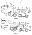
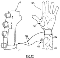
- a device for controlled pinch-grip and hand opening is illustrated in Figure 1.
- a hand 11 is shown in an open position around a drinking glass 12.
- the stimulator device generally indicated by 18, takes the form of a fingerless glove 13 worn on the hand and forearm.
- glove 13 is made principally of the elastic material neoprene, punched with small holes for breathability.
- Lycra® mesh 16 links the hand and forearm portions (18A and 18B, respectively) of glove 13 over the wrist crease 19.
- Horse-hide, deer-hide or rubber are preferred materials for forming the palm section of hand portion 18A of stimulator device 18, to maximize traction on wheel-chair rims i.e.
- Wrist position sensor 14 is illustrated with the proximal end of the sensor located in long, flat control box 15 which is held in a pouch generally indicated by 20 on the back of glove 13; although not shown, pouch 20 may be formed of a netting or other suitable material to hold box 15 in place, while permitting access to its functions as disclosed herein.
- Glove 13 has D-rings 17 which are attached to Velcro® straps (shown as 50 in Fig. 5). D-rings 17 are used to close and tighten each strap in turn.
- D-rings 17 are of a large size to enable a patient to insert a finger into a ring to pull a strap tight.
- FIG. 3 shows a cross-section of wrist position sensor 14 of the preferred embodiment of the invention.
- Wrist-position sensor 14 is an inductive transducer e.g. a linear variable displacement transducer.
- Glass tube 32 of wrist position sensor 14 is located inside control box 15.
- a thin metal stylus 33 moves in and out of glass tube 32, changing the inductance of wire coil 34 wound onto tube 32.
- the stylus 33 and an elastic cord 35 are attached to a smooth glass bead 36.
- Plastic tube 37 of wrist sensor 14 is attached to the bottom surface of control box 15.
- Elastic cord 35 is held in tension in plastic tube 37 and pulls on bead 36 and therefore pulls the stylus 33 back into tube 32 i.e. plastic tube 37 and elastic cord 35 provide spring-loading of the stylus 33.
- a durable thread 38 leads from bead 36 over the back of the wrist to ring 22 which attaches to hook 23 sewn to the back of the hand portion 18A of glove 18.
- the reduced inductance of coil 34 which this causes is decoded by electronic circuitry within box 15, providing the desire position signal.
- FIG 4 an alternative to wrist position sensor 14 of Figure 3 is shown, in cross-sectional view.
- Housing 41 of wrist position sensor 14 is contained in box 15 on glove 13, while ring 22 is attached to hook 23 on the back of the hand portion 18A of glove 18.
- a compliant elastic cord or spring 42 in sensor 14 leads to glass bead 36.
- a durable thread 38 spans the wrist joint 19.
- a protective plastic sleeve covers part of the length of cord or spring 42 from box 15 to the wrist joint.
- the compliant cord or spring 42 is attached within the housing 41 of box 15 to a cantilever element 43, which has semiconductor strain gauges 44 bonded to it.
- Fig. 4A When the wrist flexes, durable thread 38 extends compliant spring 42, and imparts increased force to the cantilever, bending it and changing the electrical resistance of the strain gauges.
- FIG. 4B Two alternate sensing elements are shown in Fig. 4A and Fig. 4B.
- Fig. 4A the bending of cantilever element 43 is detected by a Hall-effect magnetic transducer 45.
- Fig. 4B the bending of cantilever element 43 is detected by a photoelectric sensor made up of a photoemitter such as a LED 25 and a photodetector such as a photodiode 26.
- the beam transmitted from LED 25 to photodiode 26 is partially blocked by a sidearm of cantilever 43, the amount being blocked depending on the position of cantilever element 43, which in turn depends on the tension in spring 42 and therefore the position of the wrist.
- wrist position sensor 14 is of the proximity-detector type. This could either detect changes in electric or magnetic fields caused by the proximity of the adjacent limb segment, or changes in the intensity of sound or light transmitted from or reflected by the adjacent limb segment, or changes in the stretching of skin underlying part of the garment.
- Figure 5 shows adhesive FES electrode 51 and stainless mesh contact pad 52 sewn between the inner surface of the gloves and an inner lining; straps 50 are shown in a loosened condition with forearm portion 18B of glove 13 in a partially opened position.
- An example of electrode 51 is a commercially available gel electrode exemplified by Conmed Corporation of Utica, New York, Type 650-2578.
- a metal stud 53 is located on the back of electrode 51, normally intended to connect to the clasp of a snap or press-stud connecter, may be augmented in height slightly with a small metal dome. The electrode thus modified is pressed onto the skin over the muscle to the stimulated.
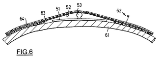
- electrode 51 and contact pad 52 are shown in cross-section with electrode 51 mounted on the user's skin 61.
- the electrode's stud or dome 53 is shown in contact with the metal mesh pad 52.
- An electrical current is transmitted by way of insulated stainless steel wire 62, metal mesh contact pad 52 and stud 53 through electrode 51 into the user's skin 61; a solid conductive gel is usually located in electrode 51.
- Dome 53 must have sufficient height to press up firmly against the mesh pad 52 through an opening cut into the neoprene inner lining 63 inside the outer neoprene shell 64 of the glove. This ensures that no part of the metal mesh 52 contacts skin 61 directly.
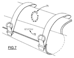
- Figure 7 illustrates an implanted, and less preferred, alternative to the surface electrode system shown in Figure 6.
- the contact pad 52 is replaced by an antenna 71, which transmits electrical energy and commands from box 15 through the skin at radio frequencies, to an implanted muscle microstimulator 72.
- the microstimulator and an external antenna might be in the form of the devices described by Schulman et al. U.S. patent 5,193,540.
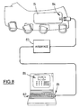
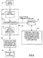
- Figure 8 shows a computer system which allows a clinician to set functional parameters of glove 13 to suit a particular user.
- An RS232 communication port 81 of a personal or lap top computer 82 is connected by interface 83 to optical receive/transmit port 84 in box 15.
- a graphics-based display 85 of the computer allows parameters such as channel allocation, pulse train profiles and sensor hysteresis (see below) to be set easily.
- a microcontroller in box 15 sends prevailing parameter settings and the wrist position signal back to the computer, allowing sensor operation to be verified and parameters to be checked.
- the block diagram of Figure 9 shows the functional relationship between the components of the system.
- the sensor block 91 shown in Figure 9 may comprise the sensor 14 of Figure 3 or of Figure 4.
- Sensor block 91 provides an output signal stimulator controller 93.
- Stimulator controller 93 consists of signal conditioner 91a for sensor 14, microcontroller 92, and stimulus pulse amplifier and router 94.
- Microcontroller 92 is preferably a Motorola 68HC11. Microcontroller 92 samples the conditioned sensor signal and on the basis of customized software provides driving signals to stimulus pulse amplifier and router 94.
- the stimulus pulse amplifier and router portion of the stimulator controller 93 provides pulse trains to appropriate contact pads and associated electrodes 95, which are preferably of the form illustrated in Figures 5 and 6 as electrode 51 and contact pad 52, but may be an antenna and implant system of the types shown in Figure 7.
- Interface 97 and computer 98 are for use by a clinician, as discussed below.
- a computer may be selectively connected, preferably by an RS232 port, to micro-controller 93 to permit software to be downloaded and stimulus channels and pulse parameters to be configured to suit each patient. Both micro-controller 93 and the computer contain software written to enable the units to carry out the functions described.
- Figure 10 illustrates a plot of the output of the wrist position sensor of the preferred embodiment on a horizontal axis 101 and a vertical axis 102, showing wrist flexion above the horizontal axis and wrist extension below the horizontal axis.
- Lines 103 and 104 show the thresholds for turning on pinch-grip FES and hand-opening FES, respectively.
- the dashed lines 105 and 106 show the thresholds for turning off pinch-grip FES and hand-opening FES stimulation, respectively.
- the difference (hysteresis) in the ON and OFF thresholds for both pinch grip and hand-opening avoids intermittent ON/OFF switching in cases where the wrist lingers close to the ON threshold.
- the wrist position crosses the threshold for triggering pinch grip FES.
- the wrist position crosses the threshold for turning off pinch grip FES.
- the wrist position crosses the threshold for triggering hand-opening FES.
- the wrist position crosses the threshold for turning off hand-opening FES.
- Figure 11 illustrates in a graphical manner the way in which the user resets threshold and stimulus intensity parameters.
- the thresholds are re-set to allow for hand opening or pinch-grip closing with varying degrees of wrist flexion or wrist extension.
- the user first places the microcontroller 93 shown in Figure 9 in re-set mode. In the preferred embodiment, this is done by pressing the OPTION button 24 on the upper surface of box 15 of Fig. 1 once.
- LED 25 of Fig. 2 next to the OPTION button starts blinking and after a second or so if the button has not been pressed again, the diode lights continuously for two-three more seconds during which time the processor is ready to receive the new threshold settings. During this 2-3 seconds, the user moves his/her wrist between the desired threshold positions.
- the microcontroller 93 of Fig. 9 records the points of greatest wrist flexion and greatest wrist extension caused by tangents 111 and 112, respectively in Figure 11.
- the point of greatest wrist flexion selected during the reset procedure is used by micro-controller 93 as the threshold for hand opening FES.
- the tangent 112 representing maximal wrist extension in Figure 11 is stored by the microcontroller as the threshold for pinch grip FES.
- the amount of hysterisis referred to above is previously set by the clinician using the computer interface 97 and 98 shown in Figure 9.
- the amount of hysterisis is expressed as a percentage of the displacement between tangent 111 and 112 in Figure 11.
- micro-controller 93 of Fig. 9 will cause the stimulus pulse generator 94 to send electrical pulses to those electrodes which are appropriate to cause hand opening. Preferably these stimulate the extensor digitorum and abductor pollicis muscles.
- extension of the wrist by the patient such that the sensor provides a signal corresponding to wrist extension greater than that of tangent 112 of Fig. 11, micro-controller 93 of Fig.
- the pulse generator 94 will cause the pulse generator 94 to provide a pulse train to those electrodes which are positioned on the patient's hand and forearm to produce thumb opposition and finger flexion by stimulating muscles, including flexor pollicis brevis and longus, opponens pollicis and flexor digitorum superficialis muscles, to produce a pinch grip.
- the patient can also pre-set the intensity of the stimulus pulse train to each active electrode.
- the patient selects an electrode by pushing the OPTION button 2, 3 or 4 times in succession. Two pushes selects the flexor pollicis longus electrode, three pushes selects extensor digitorum and so on.
- the electrode selected is indicated by one of three LEDs 25 on box 15 as shown in Fig. 2.
- Stimulus intensity can now be changed by using wrist movements. For example, if the intensity of stimulation through the thumb electrodes is too high, flexion of the wrist will decrease it. If the intensity is too low, extension of the wrist will increase it. The changes are gradual and the rate of change can be preset by the clinician using computer interface 97 and 98 shown in Fig. 9.
- the changes are indicated to the user by visual and/or auditory feedback.
- the longer the wrist is kept in flexion the greater the decrease in intensity of stimulation of the electrodes selected.
- the OPTION button is pressed to exit from the option mode. It is to be understood that the OPTION button could be replaced by a voice activated input system.
- the glove 13 shown in Figures 1 and 2 is preferably a form-fitting, elastic glove having an integral sensor of the type shown in Figure 3, or alternatively Figure 4.
- Contact pads of the type shown in Figure 5 are mounted on the interior surface of glove 13.
- the micro-processor, pulse generator and the body of the sensor are located in control box 15 which is held in a pouch on the back of the glove itself.
- the box 15 has the three push-buttons which control power, stimulus ON-OFF and option selection.
- the micro-controller, pulse generator and body of the sensor are not shown.
- the glove is worn by a user over the hand and forearm as shown in Figure 1.
- sensor 14 responds to the motion.
- the sensor signal is sampled digitally by the micro-controller 93. If the position signal exceeds the pre-set hand open threshold, micro-controller 93 provides a pulse train via the stimulus pulse generator to selected electrode contact pads in the glove 13 as shown in the block diagram of Figure 9 as block 95.
- the selected connector pad transmits pulses through the skin electrodes to the muscles on the back of the forearm which open the hand as shown in Figure 1.
- the patient may extend the wrist. If wrist extension exceeds the pre-set "pinch grip" threshold, pulses will be transmitted by the electrodes which create a pinch grip as shown in Figure 2.
- a plurality of pairs of thresholds could be pre-stored by the patient in microcontroller 93.
- a desired pair of threshold points could subsequently be selected using the option button on box 25.
- electrodes of the type shown as 51 in Figure 5 and Figure 6 must be positioned appropriately and accurately on the patient's hand and forearm over "motor points" i.e. at those places which will best give rise to stimulation of the muscles referred to above.
- the motor points have to be established empirically by the clinician during an initial fitting procedure.
- a conventional FES stimulator could be used to identify the motor points.
- the preferred embodiment of glove 13 allows external access to the output of micro-controller 93.
- Test leads 112 are connected to microcontroller box 121 by the clinician.
- Electrode 124 is anodic i.e. positive indifferent electrode.
- muscle stimulation is used to attenuate pathological tremor.
- the microcontroller is programmed to digitally filter the sampled displacement signal and accordingly stimulate muscles out-of-phase with each tremor cycle.
- all aspect of the design and use of the glove are as described herein, except for the control algorithm used by the microprocessor.
- the garment or glove provides a more convenient means of applying therapeutic muscle stimulation than existing devices.
- Controller box 15 and sensor 14 are detachable from the glove. This permits the glove to be washed. All other metallic components of the glove e.g. metal mesh and connecting wires should be resistant to corrosion. A preferred material is stainless steel.
Landscapes
- Health & Medical Sciences (AREA)
- Public Health (AREA)
- Engineering & Computer Science (AREA)
- Veterinary Medicine (AREA)
- Biomedical Technology (AREA)
- Nuclear Medicine, Radiotherapy & Molecular Imaging (AREA)
- Radiology & Medical Imaging (AREA)
- Life Sciences & Earth Sciences (AREA)
- Animal Behavior & Ethology (AREA)
- General Health & Medical Sciences (AREA)
- Cardiology (AREA)
- Physical Education & Sports Medicine (AREA)
- Heart & Thoracic Surgery (AREA)
- Electrotherapy Devices (AREA)
- Percussion Or Vibration Massage (AREA)
- Control Of Ac Motors In General (AREA)
- Control Of Electric Motors In General (AREA)
- Gloves (AREA)
- Control Of Direct Current Motors (AREA)
- Massaging Devices (AREA)
- Eye Examination Apparatus (AREA)
- Professional, Industrial, Or Sporting Protective Garments (AREA)
- Rehabilitation Tools (AREA)
Abstract
Description
Claims (16)
- An electrical stimulation garment for use by a user having muscles of reduced motor ability, said garment having an electronic controller-stimulator for stimulating said muscles of said user, characterized in that:said garment is a non-invasive self-contained functional electrical stimulation garment which may be donned in one piece by said user, said garment being adapted to fit over a joint and said muscles of said user;said garment having a sensor (14) to sense movement of said joint and which is cooperatively interconnected with an electronic controller-stimulator (15) located on said garment, said electronic controller-stimulator (15) converting sensed movement of said joint into functional electrical stimulation for said muscles; andsaid garment being adapted, when the garment is fitted on said user, to pass said functional electrical stimulation from said stimulator through electrical connections internal to said garment to electrodes on or implanted in said user to stimulate said muscles of reduced motor ability.
- The garment of Claim 1 in the form of a hand glove.
- The garment of Claim 2 in the form of a glove in which opening and closing of the hand of the user is stimulated on movement of the wrist of the user beyond threshold limits of flexion and extension thereof, with an intermediate zone between such threshold limits in which there is no stimulation to open or grip, said threshold limits being set on said controller.
- The garment of Claim 2 or Claim 3 in the form of a glove in which the thresholds of movement may be set by the user by activation of the controller-stimulator and moving the wrist between new threshold positions.
- The garment of any one of Claims 2-4 in the form of a glove in which there is an electrically-isolated communications interface with the controller-stimulator for purpose of adjusting or reviewing one or more of (a) set threshold positions for activation of stimulation for hand opening or closing, (b) stimulus parameters and (c) control logic.
- The garment of any one of Claims 2-5 in the form of a glove in which there is an alternative connection to the stimulator output stage to provide a pulse train for purpose of determining the muscle stimulation sites for said opening and closing.
- An electrical stimulation garment of any one of Claims 1-6 in which said garment is comprised of a perforated elastic material, said electrical connections (52) internal to said garment being adapted to make electrical contact with pre-positioned electrodes on said user, and said electronic controller-stimulator (15) is battery-driven and located on said garment.
- The garment of Claim 7 in which the electrical contact is formed on tightening of the garment on the user.
- The garment of any one of Claims 1-8 in which the electrical connections internal to said garment are through a metallic mesh or a metallic foil.
- The garment of any one of Claims 1-9 in which the electrodes are pre-positioned self-adhesive skin electrodes.
- The garment of any one of Claims 1-10 in which the self-adhesive skin electrodes include a stud oriented away from the skin of the user, said stud making electrical contact with the internal electrical connection of the garment on tightening the garment on the user.
- The garment of any one of Claims 2-11 in which the sensor and the controller-stimulator are located on the back of the glove.
- The garment of any one of Claim 1 and Claims 7-11 in the form of a cuff or sleeve.
- The garment of any one of Claims 1-13 when adapted for use in attenuation of tremor in a user.
- The garment of any one of Claims 1-13 when adapted for use where the reduced motor ability is quadriplegia or hemiplegia.
- The garment of any one of Claims 1-13 when adapted for use where the reduced motor ability is paraplegia.
Applications Claiming Priority (3)
| Application Number | Priority Date | Filing Date | Title |
|---|---|---|---|
| GB9321086 | 1993-10-13 | ||
| GB939321086A GB9321086D0 (en) | 1993-10-13 | 1993-10-13 | Hand stimulator |
| PCT/CA1994/000570 WO1995010323A1 (en) | 1993-10-13 | 1994-10-13 | Garment for applying controlled electrical stimulation to restore motor function |
Publications (2)
| Publication Number | Publication Date |
|---|---|
| EP0725665A1 EP0725665A1 (en) | 1996-08-14 |
| EP0725665B1 true EP0725665B1 (en) | 1998-01-14 |
Family
ID=10743453
Family Applications (1)
| Application Number | Title | Priority Date | Filing Date |
|---|---|---|---|
| EP94929437A Expired - Lifetime EP0725665B1 (en) | 1993-10-13 | 1994-10-13 | Garment for applying controlled electrical stimulation to restore motor function |
Country Status (14)
| Country | Link |
|---|---|
| US (1) | US5562707A (en) |
| EP (1) | EP0725665B1 (en) |
| JP (1) | JPH09503937A (en) |
| CN (1) | CN1135722A (en) |
| AT (1) | ATE162089T1 (en) |
| AU (1) | AU678065B2 (en) |
| BR (1) | BR9407821A (en) |
| CA (1) | CA2173430C (en) |
| DE (1) | DE69407987T2 (en) |
| DK (1) | DK0725665T3 (en) |
| ES (1) | ES2111336T3 (en) |
| GB (1) | GB9321086D0 (en) |
| PL (1) | PL174876B1 (en) |
| WO (1) | WO1995010323A1 (en) |
Cited By (2)
| Publication number | Priority date | Publication date | Assignee | Title |
|---|---|---|---|---|
| CN102319080A (en) * | 2011-08-25 | 2012-01-18 | 东南大学 | Device for measuring regularity between hand movements and hand electromyographic signals |
| US10173060B2 (en) | 2014-06-02 | 2019-01-08 | Cala Health, Inc. | Methods for peripheral nerve stimulation |
Families Citing this family (166)
| Publication number | Priority date | Publication date | Assignee | Title |
|---|---|---|---|---|
| US5957860A (en) * | 1995-08-04 | 1999-09-28 | Rodiera Olive; Jose J | Method and apparatus for monitoring and/or controlling the neuromuscular blocking, specially the blocking produced by muscular relaxing pharmaceuticals during anaesthesia |
| US5643332A (en) * | 1995-09-20 | 1997-07-01 | Neuromotion Inc. | Assembly for functional electrical stimulation during movement |
| WO1998017348A1 (en) * | 1996-10-21 | 1998-04-30 | Hangcheng Lu | Magnetotherapy device in motion |
| FR2758268B1 (en) * | 1997-01-16 | 1999-03-19 | Delatex Sa | PRE-PERFORATED NEOPRENE GARMENT FOR FIXING THE ELECTRODES OF AN EXITO MOTOR APPARATUS FOR MUSCLE ELECTROTHERAPY |
| US6007569A (en) * | 1997-02-18 | 1999-12-28 | Frenkel; Richard E. | Quantifying stress reduction and medical treatment as a result of colored light therapies |
| US7460911B2 (en) * | 1997-02-26 | 2008-12-02 | Alfred E. Mann Foundation For Scientific Research | System and method suitable for treatment of a patient with a neurological deficit by sequentially stimulating neural pathways using a system of discrete implantable medical devices |
| WO1998047426A1 (en) | 1997-04-21 | 1998-10-29 | Virtual Technologies, Inc. | Goniometer-based body-tracking device and method |
| US7472047B2 (en) * | 1997-05-12 | 2008-12-30 | Immersion Corporation | System and method for constraining a graphical hand from penetrating simulated graphical objects |
| US6042555A (en) | 1997-05-12 | 2000-03-28 | Virtual Technologies, Inc. | Force-feedback interface device for the hand |
| EP2080595A3 (en) * | 1997-05-12 | 2017-08-30 | Immersion Corporation | Force-feedback interface device for the hand |
| CA2217920A1 (en) | 1997-10-08 | 1999-04-08 | Neuromotion Inc. | Garment having controller that is activated by mechanical impact |
| DE19824504C2 (en) * | 1998-06-02 | 2001-08-16 | Albrecht Struppler | Body part stimulation device |
| US6429846B2 (en) | 1998-06-23 | 2002-08-06 | Immersion Corporation | Haptic feedback for touchpads and other touch controls |
| WO2000003760A1 (en) * | 1998-07-16 | 2000-01-27 | Delatex | Excito-motor garment |
| US6161044A (en) * | 1998-11-23 | 2000-12-12 | Synaptic Corporation | Method and apparatus for treating chronic pain syndromes, tremor, dementia and related disorders and for inducing electroanesthesia using high frequency, high intensity transcutaneous electrical nerve stimulation |
| US6445955B1 (en) * | 1999-07-08 | 2002-09-03 | Stephen A. Michelson | Miniature wireless transcutaneous electrical neuro or muscular-stimulation unit |
| ES2306495T3 (en) * | 1999-10-29 | 2008-11-01 | Compex Medical S.A | NEUROMUSCULAR ELECTRICAL STIMULATOR WITH MEASUREMENT OF MUSCULAR RESPONSES TO ELECTRICAL STIMULATION PULSES. |
| US6264621B1 (en) * | 1999-10-29 | 2001-07-24 | William C. Paske | System and method for providing quantified and qualitative hand analysis |
| US6324432B1 (en) | 1999-11-01 | 2001-11-27 | Compex Sa | Electrical neuromuscular stimulator for measuring muscle responses to electrical stimulation pulses |
| US6822635B2 (en) | 2000-01-19 | 2004-11-23 | Immersion Corporation | Haptic interface for laptop computers and other portable devices |
| US6922592B2 (en) * | 2000-04-04 | 2005-07-26 | Medtronic, Inc. | Implantable medical device controlled by a non-invasive physiological data measurement device |
| IL135585A (en) * | 2000-04-11 | 2006-10-31 | Ness Neuromuscular Electrical Stimulation Systems Ltd | Electrode positioner for a splint to be used for muscle stimulation |
| EP1285418A4 (en) * | 2000-04-12 | 2004-04-28 | Ansell Healthcare Prod Inc | Communicative glove containing embedded microchip |
| US6704603B1 (en) * | 2000-05-16 | 2004-03-09 | Lockheed Martin Corporation | Adaptive stimulator for relief of symptoms of neurological disorders |
| WO2002022205A1 (en) * | 2000-09-13 | 2002-03-21 | Alfred E. Mann Institute For Biomedical Engineering At The University Of Southern California | Method and apparatus for conditioning muscles during sleep |
| US6491649B1 (en) | 2000-10-06 | 2002-12-10 | Mark P. Ombrellaro | Device for the direct manual examination of a patient in a non-contiguous location |
| US20050149364A1 (en) * | 2000-10-06 | 2005-07-07 | Ombrellaro Mark P. | Multifunction telemedicine software with integrated electronic medical record |
| US20040097836A1 (en) * | 2000-10-06 | 2004-05-20 | Ombrellaro Mark P. | Direct manual examination of remote patient with virtual examination functionality |
| AUPR061600A0 (en) | 2000-10-10 | 2000-11-02 | D & E Consulting Pty Ltd | Method and apparatus for controlling repetitive nervous system malfunction |
| EP1359974A2 (en) * | 2001-01-16 | 2003-11-12 | B.M.R. Research and Development Limited | Apparatus for stimulating a muscle of a subject |
| WO2002085452A1 (en) | 2001-04-24 | 2002-10-31 | Neurodan A/S | Functional electrical therapy system (fets) |
| AU2002320145A1 (en) * | 2001-06-21 | 2003-01-08 | Vanderbilt University | Method for promoting reinnervation of denervated tissue |
| US7877243B2 (en) * | 2001-07-16 | 2011-01-25 | Immersion Corporation | Pivotable computer interface |
| DE20200685U1 (en) * | 2001-08-17 | 2002-03-28 | Hoeven Martin V D | Muscle electrostimulation device |
| US6644976B2 (en) | 2001-09-10 | 2003-11-11 | Epoch Innovations Ltd | Apparatus, method and computer program product to produce or direct movements in synergic timed correlation with physiological activity |
| IL145718A0 (en) | 2001-09-30 | 2002-07-25 | Ness Neuromuscular Electrical Stimulation Systems Ltd | Device for muscular stimulation |
| US6755795B2 (en) * | 2001-10-26 | 2004-06-29 | Koninklijke Philips Electronics N.V. | Selectively applied wearable medical sensors |
| US6788976B2 (en) | 2001-11-02 | 2004-09-07 | Lockheed Martin Corporation | Movement timing simulator |
| US6829510B2 (en) * | 2001-12-18 | 2004-12-07 | Ness Neuromuscular Electrical Stimulation Systems Ltd. | Surface neuroprosthetic device having an internal cushion interface system |
| AUPS006902A0 (en) | 2002-01-21 | 2002-02-07 | Neopraxis Pty Ltd | A multi-purpose fes system |
| US7231252B2 (en) * | 2002-01-21 | 2007-06-12 | Neopraxis Pty Ltd. | FES stimulator having multiple bundled leads |
| AUPS042802A0 (en) | 2002-02-11 | 2002-03-07 | Neopraxis Pty Ltd | Distributed functional electrical stimulation system |
| US20040219498A1 (en) * | 2002-04-09 | 2004-11-04 | Davidson Lance Samuel | Training apparatus and methods |
| FI112913B (en) * | 2002-06-27 | 2004-02-13 | Mega Elektroniikka Oy | Procedure for measuring the function of the muscles of the body and a garment for applying the procedure |
| EP1555968B1 (en) * | 2002-10-17 | 2018-10-31 | Rehabtronics Inc. | Method and apparatus for controlling a device or process with vibrations generated by tooth clicks |
| US7162305B2 (en) * | 2002-10-23 | 2007-01-09 | The Hong Kong Polytechnic University | Functional electrical stimulation system |
| US20070179560A1 (en) * | 2002-10-23 | 2007-08-02 | Kai-Yu Tong | Functional electrical stimulation system |
| WO2004037344A1 (en) * | 2002-10-24 | 2004-05-06 | Lockheed Martin Corporation | Systems and methods for treating movement disorders |
| US20040097838A1 (en) * | 2002-11-19 | 2004-05-20 | Paske William C. | System and apparatus for providing quantified hand analysis |
| US7725175B2 (en) * | 2002-12-04 | 2010-05-25 | Kinetic Muscles, Inc. | System and method for neuromuscular reeducation |
| AU2003297717A1 (en) | 2002-12-08 | 2004-06-30 | Immersion Corporation | Haptic messaging in handheld communication devices |
| US8059088B2 (en) | 2002-12-08 | 2011-11-15 | Immersion Corporation | Methods and systems for providing haptic messaging to handheld communication devices |
| US8830161B2 (en) | 2002-12-08 | 2014-09-09 | Immersion Corporation | Methods and systems for providing a virtual touch haptic effect to handheld communication devices |
| US7336266B2 (en) | 2003-02-20 | 2008-02-26 | Immersion Corproation | Haptic pads for use with user-interface devices |
| GB0310414D0 (en) * | 2003-05-07 | 2003-06-11 | Bmr Res & Dev Ltd | Apparatus for applying electrical current to the neuromuscular system |
| US20050049652A1 (en) * | 2003-08-25 | 2005-03-03 | Kai-Yu Tong | Functional electrical stimulation system |
| US8396565B2 (en) | 2003-09-15 | 2013-03-12 | Medtronic, Inc. | Automatic therapy adjustments |
| US20080208288A1 (en) * | 2003-10-24 | 2008-08-28 | Lockheed Martin Corporation | Systems and methods for treating movement disorders |
| ITCR20040003A1 (en) * | 2004-01-15 | 2004-04-15 | B I A C Srl | MULTIPROGRAM MUSCLE ELECTROSTIMULATOR, WITH EASY-TO-USE INTERFACE FOR THE SELECTION OF THE DESIRED PROGRAM, AND RELATED METHOD OF SELECTION |
| US20100016929A1 (en) * | 2004-01-22 | 2010-01-21 | Arthur Prochazka | Method and system for controlled nerve ablation |
| WO2005070494A1 (en) | 2004-01-22 | 2005-08-04 | Rehabtronics Inc. | Method of routing electrical current to bodily tissues via implanted passive conductors |
| US8232969B2 (en) | 2004-10-08 | 2012-07-31 | Immersion Corporation | Haptic feedback for button and scrolling action simulation in touch input devices |
| US8140165B2 (en) | 2005-01-28 | 2012-03-20 | Encore Medical Asset Corporation | Independent protection system for an electrical muscle stimulation apparatus and method of using same |
| CN1846805B (en) * | 2005-04-11 | 2011-09-07 | 香港理工大学 | Functional electric stimulation system and method |
| ES2561581T3 (en) | 2005-04-19 | 2016-02-29 | Compex Technologies, Inc. | Electrical stimulation device |
| US7825903B2 (en) | 2005-05-12 | 2010-11-02 | Immersion Corporation | Method and apparatus for providing haptic effects to a touch panel |
| US7643882B2 (en) * | 2005-05-24 | 2010-01-05 | Leon Boston | Tremor reduction systems suitable for self-application and use in disabled patients |
| AU2006261666B2 (en) | 2005-06-28 | 2011-05-26 | Bioness Inc. | Improvements to an implant, system and method using implanted passive conductors for routing electrical current |
| US20070118044A1 (en) * | 2005-07-18 | 2007-05-24 | Mega Elektroniikka Oy | Method and device for identifying; measuring and analyzing abnormal neurological responses |
| US8165685B1 (en) * | 2005-09-29 | 2012-04-24 | Case Western Reserve University | System and method for therapeutic neuromuscular electrical stimulation |
| US7899556B2 (en) | 2005-11-16 | 2011-03-01 | Bioness Neuromodulation Ltd. | Orthosis for a gait modulation system |
| US7632239B2 (en) * | 2005-11-16 | 2009-12-15 | Bioness Neuromodulation Ltd. | Sensor device for gait enhancement |
| US8972017B2 (en) | 2005-11-16 | 2015-03-03 | Bioness Neuromodulation Ltd. | Gait modulation system and method |
| US8209022B2 (en) * | 2005-11-16 | 2012-06-26 | Bioness Neuromodulation Ltd. | Gait modulation system and method |
| US7957809B2 (en) | 2005-12-02 | 2011-06-07 | Medtronic, Inc. | Closed-loop therapy adjustment |
| US9610459B2 (en) | 2009-07-24 | 2017-04-04 | Emkinetics, Inc. | Cooling systems and methods for conductive coils |
| US20070167990A1 (en) * | 2006-01-17 | 2007-07-19 | Theranova, Llc | Method and apparatus for low frequency induction therapy for the treatment of urinary incontinence and overactive bladder |
| US9339641B2 (en) * | 2006-01-17 | 2016-05-17 | Emkinetics, Inc. | Method and apparatus for transdermal stimulation over the palmar and plantar surfaces |
| EP2586489B1 (en) | 2006-05-01 | 2014-12-24 | Bioness Neuromodulation Ltd | Improved functional electrical stimulation systems |
| DE102007016083A1 (en) * | 2006-05-31 | 2007-12-06 | Mizukawa, Suehiro, Settsu | Method and device for bending a knife element |
| GB2438589A (en) * | 2006-06-01 | 2007-12-05 | Bio Medical Res Ltd | Garment with integrated electrodes and data storage for parameters related to measurement or stimulation of the wearers body |
| US9630003B2 (en) * | 2006-06-15 | 2017-04-25 | Htk Enterprises, Inc. | Non-invasive neuro stimulation system |
| US20070293917A1 (en) * | 2006-06-15 | 2007-12-20 | Thompson Thomas C | Non-invasive neuro stimulation system |
| US11224742B2 (en) | 2006-10-02 | 2022-01-18 | Emkinetics, Inc. | Methods and devices for performing electrical stimulation to treat various conditions |
| US10786669B2 (en) | 2006-10-02 | 2020-09-29 | Emkinetics, Inc. | Method and apparatus for transdermal stimulation over the palmar and plantar surfaces |
| US9005102B2 (en) | 2006-10-02 | 2015-04-14 | Emkinetics, Inc. | Method and apparatus for electrical stimulation therapy |
| AU2007303223C1 (en) | 2006-10-02 | 2013-01-10 | Emkinetics, Inc. | Method and apparatus for magnetic induction therapy |
| US8483820B2 (en) * | 2006-10-05 | 2013-07-09 | Bioness Inc. | System and method for percutaneous delivery of electrical stimulation to a target body tissue |
| US20100174342A1 (en) * | 2006-11-26 | 2010-07-08 | Leon Boston | Tremor reduction systems suitable for self-application and use in disabled patients |
| US8620438B1 (en) | 2007-02-13 | 2013-12-31 | Encore Medical Asset Corporation | Method and apparatus for applying neuromuscular electrical stimulation |
| JP5122188B2 (en) * | 2007-06-27 | 2013-01-16 | 学校法人 久留米大学 | Electrical muscle stimulation wear |
| US9757554B2 (en) | 2007-08-23 | 2017-09-12 | Bioness Inc. | System for transmitting electrical current to a bodily tissue |
| US8738137B2 (en) | 2007-08-23 | 2014-05-27 | Bioness Inc. | System for transmitting electrical current to a bodily tissue |
| US8467880B2 (en) | 2007-08-23 | 2013-06-18 | Bioness Inc. | System for transmitting electrical current to a bodily tissue |
| US8386032B2 (en) * | 2008-01-07 | 2013-02-26 | Empi Inc. | Systems and methods for therapeutic electrical stimulation |
| US8452409B2 (en) | 2008-01-07 | 2013-05-28 | Empi Inc. | Systems and methods for therapeutic electrical stimulation |
| ES2810749T3 (en) * | 2008-02-05 | 2021-03-09 | Compex Medical Sa | Stimulation orthosis |
| JP4475343B2 (en) * | 2008-04-04 | 2010-06-09 | 村田機械株式会社 | E-mail gateway device |
| US20090326602A1 (en) | 2008-06-27 | 2009-12-31 | Arkady Glukhovsky | Treatment of indications using electrical stimulation |
| US9050471B2 (en) | 2008-07-11 | 2015-06-09 | Medtronic, Inc. | Posture state display on medical device user interface |
| US9440084B2 (en) | 2008-07-11 | 2016-09-13 | Medtronic, Inc. | Programming posture responsive therapy |
| US9776008B2 (en) | 2008-07-11 | 2017-10-03 | Medtronic, Inc. | Posture state responsive therapy delivery using dwell times |
| US9662045B2 (en) | 2008-07-11 | 2017-05-30 | Medtronic, Inc. | Generation of sleep quality information based on posture state data |
| US8326420B2 (en) | 2008-07-11 | 2012-12-04 | Medtronic, Inc. | Associating therapy adjustments with posture states using stability timers |
| US8886302B2 (en) | 2008-07-11 | 2014-11-11 | Medtronic, Inc. | Adjustment of posture-responsive therapy |
| US8504150B2 (en) | 2008-07-11 | 2013-08-06 | Medtronic, Inc. | Associating therapy adjustments with posture states using a stability timer |
| US8708934B2 (en) | 2008-07-11 | 2014-04-29 | Medtronic, Inc. | Reorientation of patient posture states for posture-responsive therapy |
| US8755901B2 (en) | 2008-07-11 | 2014-06-17 | Medtronic, Inc. | Patient assignment of therapy parameter to posture state |
| US8280517B2 (en) | 2008-09-19 | 2012-10-02 | Medtronic, Inc. | Automatic validation techniques for validating operation of medical devices |
| US8776264B2 (en) * | 2009-04-03 | 2014-07-15 | Ware Llc | Garments for providing access for sensors to contact skin |
| JP5439921B2 (en) * | 2009-04-16 | 2014-03-12 | コニカミノルタ株式会社 | Tremor control device |
| US9327070B2 (en) | 2009-04-30 | 2016-05-03 | Medtronic, Inc. | Medical device therapy based on posture and timing |
| US8175720B2 (en) | 2009-04-30 | 2012-05-08 | Medtronic, Inc. | Posture-responsive therapy control based on patient input |
| US8231555B2 (en) | 2009-04-30 | 2012-07-31 | Medtronic, Inc. | Therapy system including multiple posture sensors |
| JP5447802B2 (en) * | 2009-06-30 | 2014-03-19 | 学校法人日本医科大学 | Wearable electrical stimulator |
| US8271090B1 (en) | 2009-07-02 | 2012-09-18 | Customkynetics, Inc. | Apparatus and methods for providing electrical stimulation |
| US8660656B2 (en) * | 2009-10-16 | 2014-02-25 | Hanger, Inc. | Cuff assembly |
| CA2778963A1 (en) | 2009-10-26 | 2011-05-05 | Emkinetics, Inc. | Method and apparatus for electromagnetic stimulation of nerve, muscle, and body tissues |
| US8388555B2 (en) | 2010-01-08 | 2013-03-05 | Medtronic, Inc. | Posture state classification for a medical device |
| US8579834B2 (en) | 2010-01-08 | 2013-11-12 | Medtronic, Inc. | Display of detected patient posture state |
| US9956418B2 (en) | 2010-01-08 | 2018-05-01 | Medtronic, Inc. | Graphical manipulation of posture zones for posture-responsive therapy |
| US9357949B2 (en) | 2010-01-08 | 2016-06-07 | Medtronic, Inc. | User interface that displays medical therapy and posture data |
| US9060747B2 (en) | 2010-04-16 | 2015-06-23 | The Johns Hopkins University | Device to monitor and treat hemiplegia and hemispatial neglect |
| US9566441B2 (en) | 2010-04-30 | 2017-02-14 | Medtronic, Inc. | Detecting posture sensor signal shift or drift in medical devices |
| US8588884B2 (en) | 2010-05-28 | 2013-11-19 | Emkinetics, Inc. | Microneedle electrode |
| US8197276B2 (en) | 2010-08-13 | 2012-06-12 | Djo, Llc | Low profile connector system |
| EP2618890A4 (en) * | 2010-09-20 | 2014-03-26 | Emkinetics Inc | Method and apparatus for transdermal stimulation over the palmar and plantar surfaces |
| EP2446865A1 (en) * | 2010-10-28 | 2012-05-02 | Louise Mohn | Thermostimulation apparatus |
| US9095417B2 (en) | 2011-02-07 | 2015-08-04 | Bioness Neuromodulation Ltd. | Adjustable orthosis for electrical stimulation of a limb |
| US8868217B2 (en) | 2011-06-27 | 2014-10-21 | Bioness Neuromodulation Ltd. | Electrode for muscle stimulation |
| US10368669B2 (en) | 2011-09-30 | 2019-08-06 | Verily Life Sciences Llc | System and method for stabilizing unintentional muscle movements |
| US9925034B2 (en) * | 2011-09-30 | 2018-03-27 | Verily Life Sciences Llc | Stabilizing unintentional muscle movements |
| JP5920910B2 (en) * | 2011-10-31 | 2016-05-18 | オージー技研株式会社 | Electrical stimulation device and electrical stimulation device system |
| US9907959B2 (en) | 2012-04-12 | 2018-03-06 | Medtronic, Inc. | Velocity detection for posture-responsive therapy |
| US9737719B2 (en) | 2012-04-26 | 2017-08-22 | Medtronic, Inc. | Adjustment of therapy based on acceleration |
| ES2720802T3 (en) | 2013-01-21 | 2019-07-24 | Cala Health Inc | Devices for controlling tremors |
| US9962546B2 (en) | 2013-02-21 | 2018-05-08 | Meagan Medical, Inc. | Cutaneous field stimulation with disposable and rechargeable components |
| CN103143115B (en) * | 2013-03-06 | 2015-01-21 | 浙江大学 | Recovery glove for stroke treatment |
| WO2014151431A2 (en) * | 2013-03-15 | 2014-09-25 | Emkinetics, Inc. | Method and apparatus for transdermal stimulation over the palmar and plantar surfaces |
| ES2918799T3 (en) | 2013-05-08 | 2022-07-20 | Consejo Superior Investigacion | Neuroprosthetic device for the monitoring and suppression of pathological tremors through neurostimulation of afferent pathways |
| EP3060111A1 (en) * | 2013-10-21 | 2016-08-31 | CSEM Centre Suisse d'Electronique et de Microtechnique SA - Recherche et Développement | Method and system to measure physiological signals or to electrically stimulate a body part |
| WO2015061663A1 (en) | 2013-10-25 | 2015-04-30 | Armour Technologies, Inc. | Apparatus, system, and method for reducing head or neck trauma |
| US9867985B2 (en) | 2014-03-24 | 2018-01-16 | Bioness Inc. | Systems and apparatus for gait modulation and methods of use |
| US10600596B2 (en) | 2014-04-21 | 2020-03-24 | Verily Life Sciences Llc | Adapter to attach implements to an actively controlled human tremor cancellation platform |
| US10271770B2 (en) | 2015-02-20 | 2019-04-30 | Verily Life Sciences Llc | Measurement and collection of human tremors through a handheld tool |
| US9943430B2 (en) | 2015-03-25 | 2018-04-17 | Verily Life Sciences Llc | Handheld tool for leveling uncoordinated motion |
| EP4342516A2 (en) * | 2015-06-10 | 2024-03-27 | Cala Health, Inc. | Systems and methods for peripheral nerve stimulation to treat tremor with detachable therapy and monitoring units |
| US10603482B2 (en) | 2015-09-23 | 2020-03-31 | Cala Health, Inc. | Systems and methods for peripheral nerve stimulation in the finger or hand to treat hand tremors |
| CA3010880A1 (en) | 2016-01-11 | 2017-07-20 | Bioness Inc. | Systems and apparatus for gait modulation and methods of use |
| US11344722B2 (en) | 2016-01-21 | 2022-05-31 | Cala Health, Inc. | Systems, methods and devices for peripheral neuromodulation for treating diseases related to overactive bladder |
| JP6251302B2 (en) * | 2016-01-27 | 2017-12-20 | H2L株式会社 | Electrical stimulator |
| US11571564B2 (en) * | 2016-06-02 | 2023-02-07 | Battelle Memorial Institute | Flexible sheet for neuromuscular stimulation |
| WO2018009680A1 (en) | 2016-07-08 | 2018-01-11 | Cala Health, Inc. | Systems and methods for stimulating n nerves with exactly n electrodes and improved dry electrodes |
| CA3058786A1 (en) | 2017-04-03 | 2018-10-11 | Cala Health, Inc. | Systems, methods and devices for peripheral neuromodulation for treating diseases related to overactive bladder |
| US10420663B2 (en) | 2017-05-01 | 2019-09-24 | Verily Life Sciences Llc | Handheld articulated user-assistive device with behavior control modes |
| KR101991435B1 (en) * | 2018-01-05 | 2019-06-20 | 건양대학교 산학협력단 | Rehabilitation equipment combining joint exercise therapy and functional electrical stimulation |
| US11857778B2 (en) | 2018-01-17 | 2024-01-02 | Cala Health, Inc. | Systems and methods for treating inflammatory bowel disease through peripheral nerve stimulation |
| CN108355243A (en) * | 2018-01-30 | 2018-08-03 | 深圳市未来健身衣科技有限公司 | A kind of muscle electric stimulation unit and storage medium |
| US20190352808A1 (en) * | 2018-05-17 | 2019-11-21 | Microsoft Technology Licensing, Llc | Electronically functional yarn and textile |
| US10870002B2 (en) * | 2018-10-12 | 2020-12-22 | DePuy Synthes Products, Inc. | Neuromuscular sensing device with multi-sensor array |
| CN109200461B (en) * | 2018-10-29 | 2024-04-19 | 上海体育学院 | Transcranial direct current stimulation tights for enhancing exercise capacity |
| ES2968656T3 (en) * | 2018-11-12 | 2024-05-13 | Fesia Tech S L | Functional electrical stimulation device and system |
| WO2020190407A1 (en) * | 2019-03-18 | 2020-09-24 | Exo Neural Network Inc. | Medical therapy arrangement for applying an electrical stimulation to a human or animal subject |
| US11890468B1 (en) | 2019-10-03 | 2024-02-06 | Cala Health, Inc. | Neurostimulation systems with event pattern detection and classification |
| US11331233B1 (en) * | 2020-01-02 | 2022-05-17 | Taina Rodriguez | Patient turning device with removable windows |
| US20220234591A1 (en) * | 2021-01-22 | 2022-07-28 | Toyota Research Institute, Inc. | Grip strength smart sleeves |
Family Cites Families (13)
| Publication number | Priority date | Publication date | Assignee | Title |
|---|---|---|---|---|
| US3610250A (en) * | 1967-01-10 | 1971-10-05 | Robert I Sarbacher | Electrical contact-carrying garment for muscle stimulation |
| US4391279A (en) * | 1981-12-11 | 1983-07-05 | Clinical Data, Inc. | Electrode belt |
| US4569352A (en) * | 1983-05-13 | 1986-02-11 | Wright State University | Feedback control system for walking |
| US4583547A (en) * | 1983-06-01 | 1986-04-22 | Bio-Stimu Trend Corp. | Garment apparatus for delivering or receiving electric impulses |
| US4580572A (en) * | 1983-06-01 | 1986-04-08 | Bio-Stimu Trend Corp. | Garment apparatus for delivering or receiving electric impulses |
| US4558704A (en) * | 1983-12-15 | 1985-12-17 | Wright State University | Hand control system |
| GB2186191B (en) * | 1985-11-06 | 1990-01-10 | Univ Strathclyde | Hybrid orthosis |
| US4763660A (en) * | 1985-12-10 | 1988-08-16 | Cherne Industries, Inc. | Flexible and disposable electrode belt device |
| US4785813A (en) * | 1986-02-18 | 1988-11-22 | Wright State University | Apparatus for assisting muscular contraction |
| US5067478A (en) * | 1988-06-21 | 1991-11-26 | Berlant Stephen R | Structure and method of manufacturing an electrode glove for applying electro-massage and electro-acupressure to patients |
| US4911169A (en) * | 1989-03-13 | 1990-03-27 | Ferrari Robert K | Biomedical electrode with limb band |
| IL97701A (en) * | 1991-03-28 | 1995-06-29 | Univ Ben Gurion | Device for generating hand function |
| US5193540A (en) * | 1991-12-18 | 1993-03-16 | Alfred E. Mann Foundation For Scientific Research | Structure and method of manufacture of an implantable microstimulator |
-
1993
- 1993-10-13 GB GB939321086A patent/GB9321086D0/en active Pending
-
1994
- 1994-10-13 ES ES94929437T patent/ES2111336T3/en not_active Expired - Lifetime
- 1994-10-13 BR BR9407821A patent/BR9407821A/en not_active Application Discontinuation
- 1994-10-13 WO PCT/CA1994/000570 patent/WO1995010323A1/en active IP Right Grant
- 1994-10-13 AT AT94929437T patent/ATE162089T1/en not_active IP Right Cessation
- 1994-10-13 EP EP94929437A patent/EP0725665B1/en not_active Expired - Lifetime
- 1994-10-13 PL PL94313937A patent/PL174876B1/en unknown
- 1994-10-13 DE DE69407987T patent/DE69407987T2/en not_active Expired - Fee Related
- 1994-10-13 JP JP7511129A patent/JPH09503937A/en active Pending
- 1994-10-13 DK DK94929437.5T patent/DK0725665T3/en active
- 1994-10-13 CN CN94194267.8A patent/CN1135722A/en active Pending
- 1994-10-13 AU AU78506/94A patent/AU678065B2/en not_active Ceased
- 1994-10-13 CA CA002173430A patent/CA2173430C/en not_active Expired - Fee Related
-
1995
- 1995-03-22 US US08/408,828 patent/US5562707A/en not_active Expired - Lifetime
Cited By (3)
| Publication number | Priority date | Publication date | Assignee | Title |
|---|---|---|---|---|
| CN102319080A (en) * | 2011-08-25 | 2012-01-18 | 东南大学 | Device for measuring regularity between hand movements and hand electromyographic signals |
| US10173060B2 (en) | 2014-06-02 | 2019-01-08 | Cala Health, Inc. | Methods for peripheral nerve stimulation |
| US10179238B2 (en) | 2014-06-02 | 2019-01-15 | Cala Health, Inc. | Systems for peripheral nerve stimulation |
Also Published As
| Publication number | Publication date |
|---|---|
| CA2173430C (en) | 1997-12-23 |
| CA2173430A1 (en) | 1995-04-20 |
| US5562707A (en) | 1996-10-08 |
| CN1135722A (en) | 1996-11-13 |
| PL174876B1 (en) | 1998-09-30 |
| ES2111336T3 (en) | 1998-03-01 |
| WO1995010323A1 (en) | 1995-04-20 |
| JPH09503937A (en) | 1997-04-22 |
| PL313937A1 (en) | 1996-08-05 |
| AU678065B2 (en) | 1997-05-15 |
| GB9321086D0 (en) | 1993-12-01 |
| DE69407987D1 (en) | 1998-02-19 |
| BR9407821A (en) | 1997-05-06 |
| DK0725665T3 (en) | 1998-04-14 |
| DE69407987T2 (en) | 1998-06-10 |
| EP0725665A1 (en) | 1996-08-14 |
| ATE162089T1 (en) | 1998-01-15 |
| AU7850694A (en) | 1995-05-04 |
Similar Documents
| Publication | Publication Date | Title |
|---|---|---|
| EP0725665B1 (en) | Garment for applying controlled electrical stimulation to restore motor function | |
| EP0506398B1 (en) | Device for generating hand function | |
| US8532786B2 (en) | Neural prosthesis | |
| AU2008264192B2 (en) | Method and Apparatus for Controlling a Device or Process with Vibrations Generated by Tooth Clicks | |
| US7460911B2 (en) | System and method suitable for treatment of a patient with a neurological deficit by sequentially stimulating neural pathways using a system of discrete implantable medical devices | |
| Hart et al. | A comparison between control methods for implanted FES hand-grasp systems | |
| Patel et al. | Multichannel electrotactile feedback for simultaneous and proportional myoelectric control | |
| US10046161B2 (en) | Neuroprosthetic system restoring upper limb function through coordinated electrical stimulation | |
| WO2021178914A1 (en) | System and method for determining user intention from limb or body motion or trajectory to control neuromuscular stimuation or prosthetic device operation | |
| CA2217920A1 (en) | Garment having controller that is activated by mechanical impact | |
| JPH0328225B2 (en) | ||
| Bryden et al. | An implanted neuroprosthesis for high tetraplegia | |
| JP2011010698A (en) | Wearable electrostimulator | |
| Munih et al. | Current status and future prospects for upper and lower extremity motor system neuroprostheses | |
| Prochazka et al. | Provides Controlled Grasp and Hand Opening in Quadriplegia | |
| Prochazka et al. | Provides Controlled Grasp and Hand Opening in | |
| Rupp et al. | Brain-computer interfaces for control of upper extremity neuroprostheses in individuals with high spinal cord injury | |
| Malešević | Osseointegrated Prosthesis with Neural Control and Sensory Feedback |
Legal Events
| Date | Code | Title | Description |
|---|---|---|---|
| PUAI | Public reference made under article 153(3) epc to a published international application that has entered the european phase |
Free format text: ORIGINAL CODE: 0009012 |
|
| 17P | Request for examination filed |
Effective date: 19960409 |
|
| AK | Designated contracting states |
Kind code of ref document: A1 Designated state(s): AT BE CH DE DK ES FR GB IT LI NL SE |
|
| 17Q | First examination report despatched |
Effective date: 19960925 |
|
| GRAG | Despatch of communication of intention to grant |
Free format text: ORIGINAL CODE: EPIDOS AGRA |
|
| GRAG | Despatch of communication of intention to grant |
Free format text: ORIGINAL CODE: EPIDOS AGRA |
|
| GRAH | Despatch of communication of intention to grant a patent |
Free format text: ORIGINAL CODE: EPIDOS IGRA |
|
| RAP1 | Party data changed (applicant data changed or rights of an application transferred) |
Owner name: NEUROMOTION, INC. |
|
| GRAH | Despatch of communication of intention to grant a patent |
Free format text: ORIGINAL CODE: EPIDOS IGRA |
|
| GRAA | (expected) grant |
Free format text: ORIGINAL CODE: 0009210 |
|
| AK | Designated contracting states |
Kind code of ref document: B1 Designated state(s): AT BE CH DE DK ES FR GB IT LI NL SE |
|
| REF | Corresponds to: |
Ref document number: 162089 Country of ref document: AT Date of ref document: 19980115 Kind code of ref document: T |
|
| REG | Reference to a national code |
Ref country code: CH Ref legal event code: NV Representative=s name: SCHMAUDER & WANN PATENTANWALTSBUERO, INHABER KLAUS Ref country code: CH Ref legal event code: EP |
|
| ET | Fr: translation filed | ||
| REF | Corresponds to: |
Ref document number: 69407987 Country of ref document: DE Date of ref document: 19980219 |
|
| REG | Reference to a national code |
Ref country code: ES Ref legal event code: FG2A Ref document number: 2111336 Country of ref document: ES Kind code of ref document: T3 |
|
| ITF | It: translation for a ep patent filed |
Owner name: STUDIO TORTA S.R.L. |
|
| REG | Reference to a national code |
Ref country code: DK Ref legal event code: T3 |
|
| PGFP | Annual fee paid to national office [announced via postgrant information from national office to epo] |
Ref country code: SE Payment date: 19981006 Year of fee payment: 5 |
|
| PGFP | Annual fee paid to national office [announced via postgrant information from national office to epo] |
Ref country code: FR Payment date: 19981009 Year of fee payment: 5 |
|
| PGFP | Annual fee paid to national office [announced via postgrant information from national office to epo] |
Ref country code: DK Payment date: 19981014 Year of fee payment: 5 Ref country code: AT Payment date: 19981014 Year of fee payment: 5 |
|
| PGFP | Annual fee paid to national office [announced via postgrant information from national office to epo] |
Ref country code: GB Payment date: 19981016 Year of fee payment: 5 Ref country code: DE Payment date: 19981016 Year of fee payment: 5 |
|
| PGFP | Annual fee paid to national office [announced via postgrant information from national office to epo] |
Ref country code: ES Payment date: 19981019 Year of fee payment: 5 |
|
| PGFP | Annual fee paid to national office [announced via postgrant information from national office to epo] |
Ref country code: CH Payment date: 19981022 Year of fee payment: 5 |
|
| PGFP | Annual fee paid to national office [announced via postgrant information from national office to epo] |
Ref country code: NL Payment date: 19981028 Year of fee payment: 5 |
|
| PLBE | No opposition filed within time limit |
Free format text: ORIGINAL CODE: 0009261 |
|
| STAA | Information on the status of an ep patent application or granted ep patent |
Free format text: STATUS: NO OPPOSITION FILED WITHIN TIME LIMIT |
|
| PGFP | Annual fee paid to national office [announced via postgrant information from national office to epo] |
Ref country code: BE Payment date: 19981216 Year of fee payment: 5 |
|
| 26N | No opposition filed | ||
| PG25 | Lapsed in a contracting state [announced via postgrant information from national office to epo] |
Ref country code: GB Free format text: LAPSE BECAUSE OF NON-PAYMENT OF DUE FEES Effective date: 19991013 Ref country code: DK Free format text: LAPSE BECAUSE OF NON-PAYMENT OF DUE FEES Effective date: 19991013 Ref country code: AT Free format text: LAPSE BECAUSE OF NON-PAYMENT OF DUE FEES Effective date: 19991013 |
|
| PG25 | Lapsed in a contracting state [announced via postgrant information from national office to epo] |
Ref country code: ES Free format text: LAPSE BECAUSE OF NON-PAYMENT OF DUE FEES Effective date: 19991014 |
|
| PG25 | Lapsed in a contracting state [announced via postgrant information from national office to epo] |
Ref country code: SE Free format text: THE PATENT HAS BEEN ANNULLED BY A DECISION OF A NATIONAL AUTHORITY Effective date: 19991030 |
|
| PG25 | Lapsed in a contracting state [announced via postgrant information from national office to epo] |
Ref country code: LI Free format text: LAPSE BECAUSE OF NON-PAYMENT OF DUE FEES Effective date: 19991031 Ref country code: CH Free format text: LAPSE BECAUSE OF NON-PAYMENT OF DUE FEES Effective date: 19991031 Ref country code: BE Free format text: LAPSE BECAUSE OF NON-PAYMENT OF DUE FEES Effective date: 19991031 |
|
| BERE | Be: lapsed |
Owner name: NEUROMOTION INC. Effective date: 19991031 |
|
| PG25 | Lapsed in a contracting state [announced via postgrant information from national office to epo] |
Ref country code: NL Free format text: LAPSE BECAUSE OF NON-PAYMENT OF DUE FEES Effective date: 20000501 |
|
| GBPC | Gb: european patent ceased through non-payment of renewal fee |
Effective date: 19991013 |
|
| REG | Reference to a national code |
Ref country code: CH Ref legal event code: PL |
|
| EUG | Se: european patent has lapsed |
Ref document number: 94929437.5 |
|
| PG25 | Lapsed in a contracting state [announced via postgrant information from national office to epo] |
Ref country code: FR Free format text: LAPSE BECAUSE OF NON-PAYMENT OF DUE FEES Effective date: 20000630 |
|
| NLV4 | Nl: lapsed or anulled due to non-payment of the annual fee |
Effective date: 20000501 |
|
| PG25 | Lapsed in a contracting state [announced via postgrant information from national office to epo] |
Ref country code: DE Free format text: LAPSE BECAUSE OF NON-PAYMENT OF DUE FEES Effective date: 20000801 |
|
| REG | Reference to a national code |
Ref country code: FR Ref legal event code: ST |
|
| REG | Reference to a national code |
Ref country code: ES Ref legal event code: FD2A Effective date: 20001113 |
|
| PG25 | Lapsed in a contracting state [announced via postgrant information from national office to epo] |
Ref country code: IT Free format text: LAPSE BECAUSE OF NON-PAYMENT OF DUE FEES;WARNING: LAPSES OF ITALIAN PATENTS WITH EFFECTIVE DATE BEFORE 2007 MAY HAVE OCCURRED AT ANY TIME BEFORE 2007. THE CORRECT EFFECTIVE DATE MAY BE DIFFERENT FROM THE ONE RECORDED. Effective date: 20051013 |