EP0716543B1 - Multi-picture television receiver - Google Patents
Multi-picture television receiver Download PDFInfo
- Publication number
- EP0716543B1 EP0716543B1 EP95308795A EP95308795A EP0716543B1 EP 0716543 B1 EP0716543 B1 EP 0716543B1 EP 95308795 A EP95308795 A EP 95308795A EP 95308795 A EP95308795 A EP 95308795A EP 0716543 B1 EP0716543 B1 EP 0716543B1
- Authority
- EP
- European Patent Office
- Prior art keywords
- picture
- video
- video signal
- scanning lines
- sub
- Prior art date
- Legal status (The legal status is an assumption and is not a legal conclusion. Google has not performed a legal analysis and makes no representation as to the accuracy of the status listed.)
- Expired - Lifetime
Links
Images


Classifications
-
- H—ELECTRICITY
- H04—ELECTRIC COMMUNICATION TECHNIQUE
- H04N—PICTORIAL COMMUNICATION, e.g. TELEVISION
- H04N7/00—Television systems
- H04N7/01—Conversion of standards, e.g. involving analogue television standards or digital television standards processed at pixel level
- H04N7/0117—Conversion of standards, e.g. involving analogue television standards or digital television standards processed at pixel level involving conversion of the spatial resolution of the incoming video signal
- H04N7/0122—Conversion of standards, e.g. involving analogue television standards or digital television standards processed at pixel level involving conversion of the spatial resolution of the incoming video signal the input and the output signals having different aspect ratios
-
- H—ELECTRICITY
- H04—ELECTRIC COMMUNICATION TECHNIQUE
- H04N—PICTORIAL COMMUNICATION, e.g. TELEVISION
- H04N5/00—Details of television systems
- H04N5/44—Receiver circuitry for the reception of television signals according to analogue transmission standards
- H04N5/445—Receiver circuitry for the reception of television signals according to analogue transmission standards for displaying additional information
- H04N5/45—Picture in picture, e.g. displaying simultaneously another television channel in a region of the screen
-
- H—ELECTRICITY
- H04—ELECTRIC COMMUNICATION TECHNIQUE
- H04N—PICTORIAL COMMUNICATION, e.g. TELEVISION
- H04N5/00—Details of television systems
- H04N5/44—Receiver circuitry for the reception of television signals according to analogue transmission standards
- H04N5/46—Receiver circuitry for the reception of television signals according to analogue transmission standards for receiving on more than one standard at will
Definitions
- This invention relates to a television receiver provided with a sub-picture function and more particularly to a multi-picture television receiver wherein videos can be displayed by respectively different television standard systems (such as the NTSC, PAL and SECAM) in a television receiver wherein two pictures of the same size are arranged so as to be able to be displayed.
- television standard systems such as the NTSC, PAL and SECAM
- a television receiver having a function of displaying a main picture and a sub-picture which is separate from the main picture and is a second picture a television receiver having a function of displaying respectively in substantially the same size a main picture on one side and a sub-picture on the other side by dividing a picture into two parts has been already publicized.
- the main picture shall be a picture which is displayed on the left side of the picture and is on the side out of which a synchronized signal which will be a reference in case the entire picture (both main and sub-pictures) is deflected or the like is taken.
- Fig. 17 is a block diagram showing a formation example of a conventional television receiver in which two pictures of the same size are arranged and one of the pictures can be displayed as a main picture and the other can be displayed as a sub-picture.
- a video signal for a sub-picture is output to a main picture/sub-picture superimposing part 12 through a video/chroma/deflecting processing part (called a V/C/D part hereinafter) 1, A/D converting part 2, data re-arranging part (for writing into a memory) 3, video memory 4, data re-arranging part (for reading out of the memory) 5 and D/A converting part 6.
- a writing timing generating part 7 adjusting the timing of writing data into the video memory 4 and a reading timing generating part 8 adjusting the timing of reading data out of the video memory 4 are controlled by a controlling part 9 to adjust said writing timing and reading timing on the basis of a controlling signal from the controlling part 9.
- a video signal for a main picture is output to the main picture/sub-picture superimposing part 12 through a V/C/D part 10, A/D converting part 62, video memory 63 and D/A converting part 64.
- the video memory 63 is controlled in the data writing and reading timing by a memory controlling part 61.
- the superimposed video signal is reproduced to be a tri-color signal in a video processing part 13 and is fed to a CRT 14.
- the video signal for the sub-picture is video/chroma processed in the V/C/D part 1, is separated and converted to a luminance signal and color difference signal from a composite video signal and is fed to the A/D converting part 2.
- the V/C/D part 1 separates a synchronizing signal from the composite video signal to produce a horizontal synchronizing signal (WHD) and vertical synchronizing signal (WVD) and feeds them to the writing timing generating part 7.
- the writing timing generating part 7 generates an A/D converting timing signal 15, data re-arranging timing signal 16 and data writing timing signal 17 on the basis of the WHD and WVD from the V/C/D part 1 and outputs them respectively to the A/D converting part 2, data re-arranging part (for writing into the memory) 3 and video memory 4.
- the A/D converting part 2 converts the video signal for said sub-picture to a digital signal on the basis of the A/D converting timing signal 15 and outputs it to the data re-arranging part (for writing into the memory) 3.
- the data re-arranging part (for writing into the memory) 3 re-arranges said digital converted sub-picture video signal data rows in the order adapted to writing into the memory on the basis of the data re-arranging timing signal 16 and outputs them to the video memory 4.
- the video memory 4 writes in the memory the re-arranged sub-picture video signal data rows on the basis of the data writing timing signal 17.
- the main picture video signal is video/chroma processed in the V/C/D part 10 so as to be separated and converted to a luminance signal and color difference signal from a composite video signal.
- the V/C/D part 10 separates a synchronizing signal from the composite video signal to produce a horizontal synchronizing signal (RHD) and vertical synchronizing signal (RVD) and feeds them to the reading timing generating part 8 and memory controlling part 61.
- RHD horizontal synchronizing signal
- RVD vertical synchronizing signal
- the reading timing generating part 8 generates a data reading timing signal 18, data re-arranging timing signal 19, D/A converting timing signal 20 and main picture/sub-picture switching controlling signal (YS) 11 on the basis of the RHD and RVD from the V/C/D part 10 and outputs them respectively to the video memory 4, data re-arranging part (for reading out of the memory) 5, D/A converting part 6 and main picture/sub-picture superimposing part 12.
- the sub-picture video data read out of the video memory 4 are read out at a speed about twice as high as the speed in writing and with a delay time (H/2) 1/2 time as long as a horizontal scanning period (1H) so that the sub-picture video may be displayed on half the right side on the CRT.
- the sub-picture video data are written in for a real time
- the sub-picture video data are read out for a time n times (n is a positive real number) as long as the writing time
- the sub-picture video will be compressed (or extended) to be 1/n time as large.
- the memory controlling part 61 controls the video memory 63 to write and read video data on the basis of the horizontal synchronizing signal (RHD) and vertical synchronizing signal (RVD) from the V/C/D part 10.
- RHD horizontal synchronizing signal
- RVD vertical synchronizing signal
- the re-arranged sub-picture video signal data rows written on the video memory 4 are read out of the video memory 4 on the basis of the data reading timing signal 18 generated by the reading timing generating part 8 and are output to the data re-arranging part (for reading out the memory) 5.
- the data output from the re-arranging part (for reading out the memory) 5 is re-arranged (returned) to the sub-picture video signal data rows as of before the data are re-arranged by the data re-arranging part (for writing into the memory) 3 on the basis of the data re-arranging timing signal 19 and is output to the D/A converting part 6.
- the D/A converting part 6 converts (returns) said sub-picture digital video signal to an analogue signal on the basis of the D/A converting timing signal 20 and outputs it to the main picture/sub-picture superimposing part 12.
- the main picture/sub-picture superimposing part 12 superimposes said sub-picture video signal converted to an analogue signal and said main picture video signal on each other.
- a superimposed video signal is reproduced to be a tri-color signal through the video processing part 13 and is displayed on the picture of the CRT 14.
- the television standard systems adopted today in various countries in the world are largely divided into three kinds of an NTSC system adopted mostly in Japan and America, a PAL system adopted mostly in West Europe and an SECAM system adopted mostly in old Soviet Union, France and East Europe.
- the PAL system and SECAM system are common with each other in respect that the number of scanning lines per frame is 625, whereas the NTSC system adopted in Japan, USA and so on is of the number of said scanning lines of 525 per frame and is different from the PAL system and SECAM system.
- a video of a number of scanning lines different from the number of scanning lines on the main picture has not been able to be displayed on the sub-picture simultaneously with the main picture.
- British Patent application number GB-A-2262407 discloses a television display apparatus that is adapted to display video having a different aspect ratio from the display apparatus' screen.
- the disclosure states that this is achieved by generating horizontal and vertical deflection currents to drive the scanning beam, such that the oscillating frequency of the horizontal deflection current is set corresponding to the ratio of the vertical width of the screen to the vertical width of the picture to be displayed.
- a consequence of using this technique is that when a picture with a particular aspect ratio is displayed on a screen with a different aspect ratio, there are generally one or more areas on the screen which do not display any picture.
- usable scanning lines exist in the area the document describes displaying other information in that area.
- US Patent number US-A-5,363,143 relates to the display of two images side by side on a wide screen television with correct and undistorted image aspect ratio and which minimises cropping.
- a wide screen television with a format display ratio of 16:9 two pictures displayed side by side on the screen will have a format display ratio of approximately 8:9. Therefore if the picture sources have a conventional format display ratio of 4:3, then each of the pictures must have approximately 33% of its subject matter cropped horizontally, if the resulting pictures are to have no image aspect ratio distortion.
- US-A-5,363,143 addresses this problem by reducing the vertical picture height which is considered to effectively increases the format display ratio of each side by side picture, so that much less cropping is necessary to avoid image aspect ratio.
- US Patent number US-A-5,347,318 relates to a video signal processing apparatus that can receive a number of video signals having different aspect ratios and selectively synthesising the video signals to obtain appropriate output signal for the monitor being used.
- this is achieved by discriminating between a compressed video signal of aspect ratio 9:16 (called a squeeze signal) and a normal aspect video signal (having aspect ratio 3:4) using an aspect ID.
- a squeeze signal a compressed video signal of aspect ratio 9:16
- a normal aspect video signal having aspect ratio 3:4
- the signal undergoes vertical compression by reducing the number of scan lines, with or without masking or horizontal expansion by expanding the central portion of the image.
- the signal undergoes horizontal compression with or without masking or vertical expansion.
- An object of the present invention is to provide a multi-picture television receiver wherein a video different from the number of scanning lines of a main picture can be displayed as a sub-picture simultaneously with the main picture in a television receiver having a function of displaying in substantially the same size a main picture on one side of a picture divided into two parts on the left and right and a sub-picture on the other side.
- a multi-picture television receiver for displaying simultaneously a main picture of a first video signal and a sub-picture of a second video signal comprising:
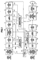
- Fig. 1 is a block diagram showing the first embodiment of the multi-picture television receiver of the present invention wherein a function of applying a vertical compression to the sub-picture video signal is added.
- the sub-picture video signal as a second video signal is output to the main picture/sub-picture superimposing part 12 as a superimposing means through a sub-picture video system discriminating part 25, V/C/D part 1, A/D converting part 2, sub-picture video vertically compressing part 23, data re-arranging part (for writing into the memory) 3, video memory 4, data re-arranging part (for reading out of the memory) 5 and D/A converting part 6.
- the V/C/D part 1, A/D converting part 2, sub-picture video vertically compressing part 23, data re-arranging part (for writing into the memory) 3, video memory 4, data re-arranging part (for reading out of the memory) 5 and D/A converting part 6 form a sub-picture video processing means.
- the sub-picture video system discriminating part 25, which forms a second discriminating means, is to discriminate whether the system is a system of a high number of scanning lines or a system of a low number of scanning lines in case there are such broadcasting systems different in the number of scanning lines as, for example, the NTSC system and PAL system or the NTSC system and SECAM system.
- the sub-picture video vertically compressing part 23 will reduce, compress in the vertical direction and output the number of scanning lines of the sub-picture video signal.
- the writing timing generating part 7 which will adjust the timing of writing data into the video memory 4 and the reading timing generating part 8 which will adjust the timing of reading data out of the video memory 4 are controlled by a controlling part 9A to adjust said writing timing and reading timing on the basis of a controlling signal.
- the controlling part 9A controls also the sub-picture video vertically compressing part 23 as to whether the vertical compression is to be made or not.
- the sub-picture video data are read out of the video memory 4 at a speed about twice as high as in writing in and with a delay time (H/2) 1/2 the horizontal scanning period (1H). Thereby, the sub-picture video is displayed on half the right side on the CRT.
- the main picture video signal as a first video signal is output to the main picture/sub-picture superimposing part 12 as a superimposing means through a main picture video system discriminating part 26, V/C/D part 10, A/D converting part 62, video memory 63 and D/A converting part 64.
- the V/C/D part 10, A/D converting part 62, video memory 63 and D/A converting part 64 form a main picture video processing means.
- the main picture video system discriminating part 26 which forms a first discriminating means, will discriminate whether the system is a system of a large number of scanning lines or a system of a small number of scanning lines.
- the video memory 63 has the data writing and reading timing controlled by the memory controlling part 61. By the way, the same as the sub-picture video data, the main picture video data are read out at a speed about twice as high as in writing into the video memory. Thereby, the main picture video is displayed on half the left side on the CRT.
- the superimposed video signal is reproduced to be a tri-color signal in the video processing part 13 and the tri-color signal is displayed on the picture of the CRT 14 as a displaying means.
- Fig. 2 is a view showing that the sub-picture displaying video will be vertically compressed and both main picture and sub-picture will be simultaneously displayed on the CRT surface in case the number of scanning lines of the sub-picture displaying video is larger than the number of scanning lines of the main picture displaying video.
- Fig. 3 is'a view showing the procedure for the display in Fig. 2.
- Displayed on the left side of the CRT surface 41 shown in Fig. 2 is the main picture video 42 and displayed on the right side is the sub-picture video 43.
- the same video shall be assumed to be displayed on the main picture and sub-picture.
- the main picture video and sub-picture video are displayed the same.
- the sub-picture video 43 is compressed in the number of scanning lines , as compared with the main picture video 42, some distortion is produced in the video. (This distortion depends on the vertically compressing method.)
- the operation of the multi-picture television receiver by said formation for such picture display shall be explained in the following.
- the video by the NTSC system is assumed to be displayed (input) in the main picture.
- the discriminating result of the sub-picture video system discriminating part 25 is fed as a discriminating result signal 21 to the controlling part 9A
- the discriminating result of the main picture video system discriminating part 26 is fed as a discriminating result signal 22 to the controlling part 9A.
- the controlling part 9A checks whether the number of scanning lines of the sub-picture is 525 lines, that is, the video signal input for the sub-picture is a video signal by the NTSC system the same as the main picture (step a1).
- the controlling part 9A will be switched by the sub-picture video vertically compressing part controlling signal 24 to a state that the sub-picture video vertically compressing part 23 will not make a compressing operation and the sub-picture will be displayed as it is.
- the controlling part 9A will control the sub-picture video vertically compressing part 23 by the sub-picture video vertically compressing part controlling signal 24 to make a compressing operation so that the number of scanning lines of the sub-picture video may be equal to the number of scanning lines of the main picture video (step a2).
- the number of scanning lines in the video displaying period of the sub-picture video equal to the number of scanning lines in the video displaying period of the main picture video is obtained by said operation. Thereby, the displayed picture shown in Fig. 2 is obtained.
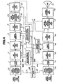
- Fig. 4 is a block diagram showing the second embodiment of the multi-picture television receiver of the present invention wherein a function of applying a blanking process to the video signal for the sub-picture is added.
- the sub-picture video signal as a second video signal is output to the main picture/sub-picture superimposing part 12 as a superimposing means through a sub-picture video system discriminating part 25, V/C/D part 1, A/D converting part 2, data re-arranging part (for writing into the memory) 3, video memory 4, data re-arranging part (for reading out of the memory) 5, sub-picture video blanking part 29 and D/A converting part 6.
- the V/C/D part 1, A/D converting part 2, data re-arranging part (for writing into the memory) 3, video memory 4, data re-arranging part (for reading out of the memory) 5, sub-picture video blanking part 29 and D/A converting part 6 form a sub-picture video processing means.
- the sub-picture video system discriminating part 25 which forms a second discriminating means, will discriminate whether it is of a system of a large number of scanning lines or a system of a small number of scanning lines.
- the sub-picture video blanking part 29 will blank at least one video signal part of the upper part and lower part of the sub-picture video signal and will reduce and output the number of scanning lines.
- the writing timing generating part 7 adjusting the timing of writing data into the video memory 4 and the reading timing generating part 8 adjusting the timing of reading data out of the video memory 4 are controlled by a controlling part 9B to adjust said writing timing and reading timing on the basis of a controlling signal.
- the controlling part 9B controls also the sub-picture video blanking part 29 as to whether the blanking process is to be made or not.
- the sub-picture video data read out of the video memory 4 are read out at a speed about twice as high as in writing in and with a delay time (H/2) 1/2 the horizontal scanning period (1H) so that the sub-picture video may be displayed on half the right side on the CRT.
- the main picture video signal as a first video signal is output to the main picture/sub-picture superimposing part 12 through a main picture video system discriminating part 26, V/C/D part 10, A/D converting part 62, video memory 63 and D/A converting part 64.
- the V/C/D part 10, A/D converting part 62, video memory 63 and D/A converting part 64 form a main picture video processing means.
- the main picture video system discriminating part 26 which forms a first discriminating means, will discriminate whether the system is a system of a large number of scanning lines or a small number of scanning lines.
- the video memory 63 is controlled by the memory controlling part 61 in the timing of writing and reading data. By the way, the same as the sub-picture video data, the main picture video data are read out at a speed about twice as high as in writing into the video memory 63 so that the main picture video may be displayed on half the left side on the CRT.
- the superimposed video signal is reproduced to be a tri-color signal in the video processing part 13 and the tri-color signal is displayed on the picture of the CRT 14 as a displaying means.
- Fig. 5 is a view showing that, in case the number of scanning lines of the sub-picture displaying video is larger than the number of scanning lines of the main picture displaying video, the displaying video of the sub-picture will be blanked and both main picture and sub-picture will be simultaneously displayed on the CRT surface.
- Fig. 6 is a view showing the procedure for the display in Fig. 5.
- Displayed on the left side of the CRT surface 41 shown in Fig. 5 is the main picture video 42 and displayed on the right side is the sub-picture video 43.
- the sub-picture video 43 is displayed as somewhat extended.
- the blanked sub-picture video 51 that is, the number of scanning lines of 525 is exceeded, there is a sub-picture video not displayed on the picture.
- the operation of the multi-picture television receiver by said formation for such picture display shall be explained in the following.
- the video by the NTSC system is displayed (input) on the main picture.
- the discriminating result of the sub-picture video system discriminating part 25 is fed as a discriminating result signal 21 to the controlling part 9B and the discriminating result of the main picture video system discriminating part 26 is fed as a discriminating result signal 22 to the controlling part 9B.
- the controlling part 9B checks whether the number of scanning lines of the sub-picture is 525, that is, whether the video signal input for the sub-picture is a video signal by the NTSC system the same as the main picture (step b1).
- the controlling part 9B will switch the sub-picture video blanking part 29 by a sub-picture video blanking part controlling signal 30 not to make a blanking process and the sub-picture will be displayed as it is.
- the controlling part 9B will control the sub-picture video blanking part 29 by the sub-picture video blanking part controlling signal 30 to operate to make the effective number of scanning lines 525 by blanking the upper side and/or lower side of the sub-picture video signal so that the number of scanning lines of the sub-picture video may be equal to the number of scanning lines of the main picture video (step b2).
- the number of scanning lines in the video displaying period of the sub-picture video equal to the number of scanning lines in the video displaying period of the main picture video is obtained and thereby the displayed picture shown in Fig. 5 is obtained.
- the blanking process is made in order to prevent this blanked sub-picture video 51 from giving bad influence to the normal displayed picture video in a vertical flyback time.
- Fig. 7 is a block diagram showing the third embodiment of the multi-picture television receiver of the present invention wherein a function of not taking excess scanning lines out of the sub-picture video signal is added.
- the sub-picture video signal as a second video signal is output to the main picture/sub-picture superimposing part as a superimposing means 12 through a sub-picture video system discriminating part 25, V/C/D part 1, A/D converting part 2, data re-arranging part (for writing into the memory) 3, video memory 4, data re-arranging part (for reading out of the memory) 5 and D/A converting part 6.
- the V/C/D part 1, A/D converting part 2, data re-arranging part (for writing into the memory) 3, video memory 4, data re-arranging part (for reading out of the memory) 5 and D/A converting part 6 form a sub-picture video processing means.
- the sub-picture video system discriminating part 25 which forms a second discriminating means, will discriminate whether the system is a system of a large number of scanning lines or of a small number of scanning lines.
- the writing timing generating part 7 adjusting the timing of writing data into the video memory 4 and the reading timing generating part 8 adjusting the timing of reading data out of the video memory 4 are controlled by a controlling part 9C to adjust said writing timing and the reading timing on the basis of a controlling signal.
- the sub-picture video data read out of the video memory 4 are read out at a speed about twice as high as in writing in and with a delay time (H/2) 1/2 the horizontal scanning period (1H) so that the sub-picture video may be displayed on half the right side on the CRT.
- the main picture video signal as a first video signal is output to the main picture/sub-picture superimposing part 12 as a superimposing means through a main picture video system discriminating part 26, V/C/D part 10, A/D converting part 62, video memory 63 and D/A converting part 64.
- the V/C/D part 10, A/D converting part 62, video memory 63 and D/A converting part 64 form a main picture video processing means.
- the main picture video system discriminating part 26 which forms a first discriminating means, will discriminate whether the system is a system of a large number of scanning lines or a system of a small number of scanning lines.
- the video memory 63 is controlled by the memory controlling part 61 in the data writing and reading timing. By the way, the same as the sub-picture video data, the main picture video data are read out at a speed about twice as high as in writing into the video memory 63 and thereby the main picture video is displayed on half the left side on the CRT.
- the superimposed video signal is reproduced to be a tri-color signal in the video processing part 13 and the tri-color signal is displayed on the picture of the CRT 14 as a displaying means.
- Fig. 8 is a view showing that, in case the number of scanning lines of the sub-picture displaying video is larger than the number of scanning lines of the main picture displaying video, excess scanning lines will not be taken out of the sub-picture video memorized in the video memory 4 and both main picture and sub-picture will be displayed simultaneously on the CRT surface.
- Fig. 9 is a view showing the procedure for the display in Fig. 8.
- Displayed on the left side of the CRT surface 41 shown in Fig. 8 is the main picture video 42 and displayed on the right side is the sub-picture video 43.
- the sub-picture video 43 is displayed as somewhat extended in the vertical direction.
- the operation of the multi-picture television receiver by said formation for such picture display shall be explained in the following.
- the video by the NTSC system is displayed (input) on the main picture.
- the discriminating result of the sub-picture video system discriminating part 25 is fed as a discriminating result signal 21 to the controlling part 9C.
- the discriminating result of the main picture video system discriminating part 26 is fed as a discriminating result signal 22 to the controlling part 9C.
- the controlling part 9C checks whether the number of scanning lines of the sub-picture is 525, that is, whether the video signal input for the sub-picture is a video signal by the NTSC system the same as the main picture (step c1). If it is a video signal by the NTSC system, the controlling part 9C will be switched through the reading timing generating part 8C to a mode of unconditionally reading out the information written into the video memory 4 and the sub-picture video will be displayed as it is.
- the controlling part 9C will control by the data reading timing signal 18 generated by the reading timing generating part 8C through the reading timing generating part 8C so that the video memory 4 may not read out the specific region (address), that is, so that the number of scanning lines of the sub-picture video may be equal to the number of scanning lines of the main picture video and the memory region (address) in which the scanning lines corresponding to the upper side and/or lower side of the sub-picture video signal are housed may not be read out (step c2).
- the number of scanning lines in the video displaying period of the sub-picture video equal to the number of scanning lines in the video displaying period of the main picture video is obtained and thereby the displaying picture shown in Fig. 8 is obtained.
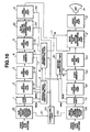
- Fig. 10 is a block diagram showing the fourth embodiment of the multi-picture television receiver of the present invention wherein a function of applying the DC superimposing process to the sub-picture video signal is added.
- the sub-picture video signal as a second video signal is output to the main picture/sub-picture superimposing part 12 as a superimposing means through a sub-picture video system discriminating part 25, V/C/D part 1, A/D converting part 2, data re-arranging part (for writing into the memory) 3, video memory 4, data re-arranging part (for reading out of the memory) 5, sub-picture video DC (direct current) superimposing part 32 and D/A converting part 6.
- the V/C/D part 1, A/D converting part 2, data re-arranging part (for writing into the memory) 3, video memory 4, data re-arranging part (for reading out of the memory) 5, sub-picture video DC (direct current) superimposing part 32 and D/A converting part 6 form a sub-picture video processing means.
- the sub-picture video system discriminating part 25 which forms a second discriminating means, will discriminate whether the system is a system of a large number of scanning lines or a system of a small number of scanning lines.
- the sub-picture video DC superimposing part 32 When the number of scanning lines of the sub-picture video signal is smaller than the number of scanning lines of the main picture video signal, the sub-picture video DC superimposing part 32 will add another video information to the sub-picture video signal and will increase and output the number of scanning lines.
- the added video information is a DC component giving a specific brightness or a DC component containing a color signal and luminance signal for giving color information by a specific brightness.
- the writing timing generating part 7 adjusting the timing of writing data into the video memory 4 and the reading timing generating part 8 adjusting the timing of reading data out of the video memory 4 are controlled by a controlling part 9D to adjust said writing timing and reading timing on the basis of a controlling signal.
- the controlling part 9D controls also the sub-picture DC (direct current) superimposing part 32 as to whether the DC superimposing process is to be made or not.
- the sub-picture video data read out of the video memory 4 are read out at a speed about twice as high as in writing in and with a delay time (H/2) 1/2 the horizontal scanning period (1H) so that the sub-picture video may be displayed on half the right side on the CRT.
- the main picture video signal as a first video signal is output to the main picture/sub-picture superimposing part 12 as a superimposing means through a main picture video system discriminating part 26, V/C/D part 10, A/D converting part 62, video memory 63 and D/A converting part 64.
- the V/C/D part 10, A/D converting part 62, video memory 63 and D/A converting part 64 form a main picture video processing means. In case the .
- the main picture video system discriminating part 26 which forms a first discriminating means, will discriminate whether the system is a system of a large number of scanning lines or a system of a small number of scanning lines.
- the video memory 63 has the data writing and reading timing controlled by the memory controlling part 61. By the way, the same as the sub-picture video data, the main picture video data are read out at a speed about twice as high as in writing into the video memory 63 so that the main picture video may be displayed on half the left side on the CRT.
- the superimposed video signal is reproduced in the video processing part 13 to be a tri-color signal and the tri-color signal is displayed on the picture of the CRT 14 as a displaying means.
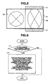
- Fig. 11 is a view showing that, in case the number of scanning lines of the sub-picture displaying video is smaller than the number of scanning lines of the main picture displaying video, the sub-picture displaying video will be DC superimposed so that the both main picture and sub-picture may be simultaneously displayed on the CRT surface.
- Fig. 12 is a view showing the procedure for the display in Fig. 11.
- Displayed on the left side of the CRT surface 45 shown in Fig. 11 is the main picture video 46 and displayed on the right side is the sub-picture video 47.
- the sub-picture video 47 is shorter in the vertical length (due to the difference in the number of scanning lines) and therefore there are videoless parts 52 above and below.
- the discriminating result of the sub-picture video system discriminating part 25 is fed as a discriminating signal 21 to the controlling part 9D and the discriminating result of the main picture video system discriminating part 26 is fed as a discriminating signal 22 to the controlling part 9D.
- the controlling part 9D checks whether the number of scanning lines of the sub-picture is 625 lines, that is, whether the video signal input for the sub-picture is a video signal by the PAL system (or SECAM system) the same as the main picture (step d1).
- the controlling part 9D will switch by the sub-picture video DC superimposing part controlling signal 33 to a state that the sub-picture video DC superimposing part 32 will not make a DC superimposing process.
- the sub-picture will be displayed as it is.
- step dl if the video signal input for the sub-picture is not a video signal by the PAL system (or SECAM system), that is, in case it is of the NTSC system, the controlling part 9D will control the sub-picture video DC superimposing part 32 by the sub-picture video DC superimposing part controlling signal 33 to add DC superimposed scanning lines to the upper side and/or lower side of the sub-picture video signal so that the number of scanning lines of the sub-picture video may be equal to the number of scanning lines of the main picture video (step d2).
- the number of scanning lines in the video displaying period of the sub-picture video equal to the number of scanning lines in the video displaying period of the main picture video is obtained and thereby the displayed picture shown in Fig. 11 is obtained.
- the videoless parts 52 shown in Fig. 11 can display any desired color with a desired luminance by the value of the superimposed DC.
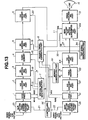
- Fig. 13 is a block diagram showing the fifth embodiment of the multi-picture television receiver of the present invention wherein a text signal generating function is added to supplement the scanning lines lacking part of the video signal for the sub-picture with a text signal having text data information.
- the sub-picture video signal as a second video signal is output to a main picture/sub-picture superimposing part 12A as a superimposing means through a sub-picture video system discriminating part 25, V/C/D part 1, A/D converting part 2, data re-arranging part (for writing into the memory) 3, video memory 4, data re-arranging part (for reading out of the memory) 5 and D/A converting part 6.
- the V/C/D part 1, A/D converting part 2, data re-arranging part (for writing into the memory) 3, video memory 4, data re-arranging part (for reading out of the memory) 5 and D/A converting part 6 form a sub-picture video processing means.
- the sub-picture video system discriminating part 25 which forms a second discriminating means, will discriminate whether the system is a system of a large number of scanning lines or a system of a small number of scanning lines.
- the writing timing generating part 7 adjusting the timing of writing data into the video memory 4 and the reading timing generating part 8 adjusting the timing of reading data out of the video memory 4 are controlled by a controlling part 9E to adjust said writing timing and reading timing on the basis of a controlling signal.
- the controlling part 9E controls the timing of outputting the text signal to the main picture/sub-picture superimposing part 12A by the text signal generating part 34.
- the sub-picture video data read out of the video memory 4 are read out at a speed about twice as high as in writing in and with a delay time (H/2) 1/2 the horizontal scanning period (1H) so that the sub-picture video may be displayed on half the right side on the CRT.
- the text signal generating part 34 which forms a means generating text information, generates and feeds text data to the main picture/sub-picture superimposing part 12A and feeds the switching signal (YS) 27 for inserting said text data into at least one of the upper part and lower part of the sub-picture to the main picture/sub-picture superimposing part 12A.
- the main picture/sub-picture superimposing part 12A is provided with not only a function of selecting, switching and outputting in a horizontal direction the main picture video signal and sub-picture video signal compressed to be 1/2 in the horizontal direction but also a function of inserting the text signal into at least one of the parts corresponding to the upper side and lower side of the picture of the sub-picture video signal compressed to' be 1/2 in the horizontal direction and outputting the sub-picture video signal containing the text signal.
- the main picture video signal as a first video signal is output to the main picture/sub-picture superimposing part 12 as a superimposing means through a main picture video system discriminating part 26, V/C/D part 10, A/D converting part 62, video memory 63 and D/A converting part 64.
- the V/C/D part 10, A/D converting part 62, video memory 63 and D/A converting part 64 form a main picture video processing means.
- the main picture video system discriminating part 26 which forms a first discriminating means, will discriminate whether the system is a system of a large number of scanning lines or a system of a small number of scanning lines.
- the video memory 63 has the writing and reading timing controlled by the memory controlling part 61.
- the main picture video data are read out at a speed about twice as high as in writing into the video memory 63 so that the main picture video may be displayed at a seed about twice as high as in writing into the video memory 63 so that the main picture video may be displayed on half the left side on the CRT.
- the superimposed video signal is reproduced in the video processing part 13 to be a tri-color signal which is displayed on the picture of the CRT 14 as a displaying means.
- Fig. 14 is a view showing that, in case the number of scanning lines of the sub-picture displaying video is smaller than the number of scanning lines of the main picture displaying video, the text data will be inserted into the blank part of the displayed video of the sub-picture and both main picture and sub-picture will be simultaneously displayed on the CRT surface.
- Fig. 15 is a view showing the procedure for the display in Fig. 14.
- Displayed on the left side of the CRT surface 45 shown in Fig. 14 is the main picture video 46 and displayed on the right side is the sub-picture video 47.
- the sub-picture video 47 is shorter in the vertical length (due to the difference in the number of scanning lines) and therefore a videoless part is produced on the upper side. Therefore, said videoless part is filled with the text picture 53 based on the text signal generated by the text signal generating part 34.
- the discriminating result of the sub-picture video system discriminating part 25 is fed as a discriminating result signal 21 to the controlling part 9E and the discriminating result of the main picture video system discriminating part 26 is fed as a discriminating result signal 22 to the controlling part 9E.
- the controlling part 9E checks whether the number of scanning lines of the sub-picture is 625 lines, that is, whether the video signal input for the sub-picture is a video signal by the PAL system (or SECAM system) the same as the main picture (step e1). If it is a video signal by the PAL system (or SECAM system), the controlling part 9E will display the sub-picture as it is.
- step el if the video signal input for the sub-picture is not a video signal by the PAL system (or SECAM system), that is, in case it is of the NTSC system, the controlling part 9E will control the text signal generating part 34.
- the controlling part 9E will control the text signal generating part 34 with the controlling signal 35 to add the text signal generated in the text signal generating part 34 to the upper side and/or lower side outside the video period of the sub-picture so that the sum of the the number of scanning lines based on the text signal and the number of scanning lines in the displaying period of the sub-picture may be equal to the number of scanning lines in the video period of the main picture and will control so that the number of scanning lines of the sub-picture video may be equal to the number of scanning lines of the main picture video.
- the text data are added to the sub-picture signal by using the switching signal 27 in the main picture/sub-picture superimposing part 12A (step e2).
- Fig. 16 is a block diagram showing the sixth embodiment of the multi-picture television receiver of the present invention wherein a character broadcast or character screen broadcast decoder is added to supplement the number of scanning lines of the sub-picture video signal lacking part with a text signal having text data information.
- the embodiment shown in Fig. 16 is of a formation wherein said text signal generating part 34 in the embodiment in Fig. 13 is replaced with a character decoder 34A for character broadcasts or character screen broadcasts.
- the character decoder 34A for character broadcasts or character screen broadcasts is to decode a text signal of a character broadcast or character screen broadcast superimposed in a main picture video signal and output it to the main picture/sub-picture superimposing part 12A.
- a text signal of a character broadcast or character screen broadcast can be displayed on the text picture 53 shown in Fig. 14.
- the television systems to be received are only three kinds of the NTSC system, PAL system and SECAM system and the television system to be received on the main picture has been explained as limited to the NTSC system or PAL system.
- the present invention is not limited to it and can be applied also to another television system.
- videos by such television systems different in the number of scanning lines as, for example, the PAL and NTSC can be simultaneously displayed and viewed.
Description
- This invention relates to a television receiver provided with a sub-picture function and more particularly to a multi-picture television receiver wherein videos can be displayed by respectively different television standard systems (such as the NTSC, PAL and SECAM) in a television receiver wherein two pictures of the same size are arranged so as to be able to be displayed.
- In a television receiver having a function of displaying a main picture and a sub-picture which is separate from the main picture and is a second picture, a television receiver having a function of displaying respectively in substantially the same size a main picture on one side and a sub-picture on the other side by dividing a picture into two parts has been already publicized. Hereafter, for the sake of convenience, the main picture shall be a picture which is displayed on the left side of the picture and is on the side out of which a synchronized signal which will be a reference in case the entire picture (both main and sub-pictures) is deflected or the like is taken.
- Fig. 17 is a block diagram showing a formation example of a conventional television receiver in which two pictures of the same size are arranged and one of the pictures can be displayed as a main picture and the other can be displayed as a sub-picture.
- In Fig. 17, a video signal for a sub-picture is output to a main picture/
sub-picture superimposing part 12 through a video/chroma/deflecting processing part (called a V/C/D part hereinafter) 1, A/D converting part 2, data re-arranging part (for writing into a memory) 3,video memory 4, data re-arranging part (for reading out of the memory) 5 and D/A converting part 6. A writingtiming generating part 7 adjusting the timing of writing data into thevideo memory 4 and a readingtiming generating part 8 adjusting the timing of reading data out of thevideo memory 4 are controlled by a controllingpart 9 to adjust said writing timing and reading timing on the basis of a controlling signal from the controllingpart 9. - On the other hand, a video signal for a main picture is output to the main picture/
sub-picture superimposing part 12 through a V/C/D part 10, A/D converting part 62,video memory 63 and D/A converting part 64. By the way, thevideo memory 63 is controlled in the data writing and reading timing by amemory controlling part 61. - The superimposed video signal is reproduced to be a tri-color signal in a
video processing part 13 and is fed to aCRT 14. - The operation of the television receiver wherein two pictures of the same size are arranged so as to be able to be displayed , one of the pictures is made a main picture and the other is made a sub-picture as formed as in the above shall be explained in the following.
- The video signal for the sub-picture is video/chroma processed in the V/C/D part 1, is separated and converted to a luminance signal and color difference signal from a composite video signal and is fed to the A/
D converting part 2. The V/C/D part 1 separates a synchronizing signal from the composite video signal to produce a horizontal synchronizing signal (WHD) and vertical synchronizing signal (WVD) and feeds them to the writingtiming generating part 7. - The writing
timing generating part 7 generates an A/D convertingtiming signal 15, datare-arranging timing signal 16 and datawriting timing signal 17 on the basis of the WHD and WVD from the V/C/D part 1 and outputs them respectively to the A/D converting part 2, data re-arranging part (for writing into the memory) 3 andvideo memory 4. - The A/
D converting part 2 converts the video signal for said sub-picture to a digital signal on the basis of the A/D convertingtiming signal 15 and outputs it to the data re-arranging part (for writing into the memory) 3. The data re-arranging part (for writing into the memory) 3 re-arranges said digital converted sub-picture video signal data rows in the order adapted to writing into the memory on the basis of the datare-arranging timing signal 16 and outputs them to thevideo memory 4. Thevideo memory 4 writes in the memory the re-arranged sub-picture video signal data rows on the basis of the datawriting timing signal 17. - On the other hand, the main picture video signal is video/chroma processed in the V/C/
D part 10 so as to be separated and converted to a luminance signal and color difference signal from a composite video signal. The V/C/D part 10 separates a synchronizing signal from the composite video signal to produce a horizontal synchronizing signal (RHD) and vertical synchronizing signal (RVD) and feeds them to the readingtiming generating part 8 andmemory controlling part 61. - The reading
timing generating part 8 generates a datareading timing signal 18, datare-arranging timing signal 19, D/A convertingtiming signal 20 and main picture/sub-picture switching controlling signal (YS) 11 on the basis of the RHD and RVD from the V/C/D part 10 and outputs them respectively to thevideo memory 4, data re-arranging part (for reading out of the memory) 5, D/A converting part 6 and main picture/sub-picture superimposing part 12. By the way, the sub-picture video data read out of thevideo memory 4 are read out at a speed about twice as high as the speed in writing and with a delay time (H/2) 1/2 time as long as a horizontal scanning period (1H) so that the sub-picture video may be displayed on half the right side on the CRT. This is because, if it is assumed that the sub-picture video data are written in for a real time, in case the sub-picture video data are read out for a time n times (n is a positive real number) as long as the writing time, the sub-picture video will be compressed (or extended) to be 1/n time as large. - In the same manner, the
memory controlling part 61 controls thevideo memory 63 to write and read video data on the basis of the horizontal synchronizing signal (RHD) and vertical synchronizing signal (RVD) from the V/C/D part 10. By the way, in case the main picture video data are read out of thevideo memory 63, the same as in the case of the sub-picture video data, the main picture video data will be read out at a speed about twice as high as the speed in writing so that the main picture may be displayed on half the left side on the CRT. - On the other hand, the re-arranged sub-picture video signal data rows written on the
video memory 4 are read out of thevideo memory 4 on the basis of the datareading timing signal 18 generated by the readingtiming generating part 8 and are output to the data re-arranging part (for reading out the memory) 5. The data output from the re-arranging part (for reading out the memory) 5 is re-arranged (returned) to the sub-picture video signal data rows as of before the data are re-arranged by the data re-arranging part (for writing into the memory) 3 on the basis of the datare-arranging timing signal 19 and is output to the D/A converting part 6. The D/A converting part 6 converts (returns) said sub-picture digital video signal to an analogue signal on the basis of the D/A convertingtiming signal 20 and outputs it to the main picture/sub-picturesuperimposing part 12. - The main picture/
sub-picture superimposing part 12 superimposes said sub-picture video signal converted to an analogue signal and said main picture video signal on each other. A superimposed video signal is reproduced to be a tri-color signal through thevideo processing part 13 and is displayed on the picture of theCRT 14. - Now, the television standard systems adopted today in various countries in the world are largely divided into three kinds of an NTSC system adopted mostly in Japan and America, a PAL system adopted mostly in West Europe and an SECAM system adopted mostly in old Soviet Union, France and East Europe. Among them, the PAL system and SECAM system are common with each other in respect that the number of scanning lines per frame is 625, whereas the NTSC system adopted in Japan, USA and so on is of the number of said scanning lines of 525 per frame and is different from the PAL system and SECAM system.
- Therefore, in the conventional television receiver having a function of displaying in substantially the same size a main picture on one side of a picture divided into two parts and a sub-picture on the other side, a video of a number of scanning lines different from the number of scanning lines on the main picture has not been able to be displayed on the sub-picture simultaneously with the main picture.
- British Patent application number GB-A-2262407 discloses a television display apparatus that is adapted to display video having a different aspect ratio from the display apparatus' screen. The disclosure states that this is achieved by generating horizontal and vertical deflection currents to drive the scanning beam, such that the oscillating frequency of the horizontal deflection current is set corresponding to the ratio of the vertical width of the screen to the vertical width of the picture to be displayed. A consequence of using this technique is that when a picture with a particular aspect ratio is displayed on a screen with a different aspect ratio, there are generally one or more areas on the screen which do not display any picture. To address this problem, since usable scanning lines exist in the area, the document describes displaying other information in that area.
- US Patent number US-A-5,363,143 relates to the display of two images side by side on a wide screen television with correct and undistorted image aspect ratio and which minimises cropping. For a wide screen television with a format display ratio of 16:9, two pictures displayed side by side on the screen will have a format display ratio of approximately 8:9. Therefore if the picture sources have a conventional format display ratio of 4:3, then each of the pictures must have approximately 33% of its subject matter cropped horizontally, if the resulting pictures are to have no image aspect ratio distortion. US-A-5,363,143 addresses this problem by reducing the vertical picture height which is considered to effectively increases the format display ratio of each side by side picture, so that much less cropping is necessary to avoid image aspect ratio.
- US Patent number US-A-5,347,318 relates to a video signal processing apparatus that can receive a number of video signals having different aspect ratios and selectively synthesising the video signals to obtain appropriate output signal for the monitor being used. In the disclosure, this is achieved by discriminating between a compressed video signal of aspect ratio 9:16 (called a squeeze signal) and a normal aspect video signal (having aspect ratio 3:4) using an aspect ID. Where a normal monitor is being used and a squeeze signal is detected, the signal undergoes vertical compression by reducing the number of scan lines, with or without masking or horizontal expansion by expanding the central portion of the image. Conversely where a wide monitor is being used and a normal signal is detected, the signal undergoes horizontal compression with or without masking or vertical expansion.
- An object of the present invention is to provide a multi-picture television receiver wherein a video different from the number of scanning lines of a main picture can be displayed as a sub-picture simultaneously with the main picture in a television receiver having a function of displaying in substantially the same size a main picture on one side of a picture divided into two parts on the left and right and a sub-picture on the other side.
- According to an embodiment of the present invention there is provided a multi-picture television receiver for displaying simultaneously a main picture of a first video signal and a sub-picture of a second video signal comprising:
- a displaying means;
- a main picture video processing means for compressing in a horizontal direction said first video signal;
- a sub-picture video processing means for compressing in a horizontal direction said second video signal; and
- a superimposing means for receiving an output signal of said main picture video processing means and an output signal of said sub-picture video processing means, and for selecting, switching and feeding the respective output signals to said displaying means; characterized in that said sub-picture video processing means includes:
- a first discriminating means for discriminating the number of scanning lines of the first video signal;
- a second discriminating means for discriminating the number of scanning lines of the second video signal; and
- a means for changing the number of scanning lines of said second video signal where said first and second video signals have different numbers of scanning lines;
- a controlling means which controls said means for changing on the basis of the discriminating results of said first and second discriminating means such that, where the number of scanning lines of said second video signal is larger than the number of scanning lines of said first video signal, the number of scanning lines of the second video signal is decreased, and where the number of scanning lines of said second video signal is smaller than the number of scanning lines of said first video signal, the number of scanning lines of the second video signal is increased, so that the number of scanning lines in said first picture and the number of scanning lines in said sub-picture may be equal to each other.
-
- According to this embodiment of the present invention, as the means of compressing said second video signal in the vertical direction on the basis of the discriminating results of the first and second discriminating means in case the number of scanning lines of the second video signal is larger or smaller than the number of scanning lines of the first video signal is provided, two video signals different in the system of the video signal can be displayed simultaneously on the left and right on one CRT.
-
- Fig. 1 is a block diagram showing the first embodiment of the multi-picture television receiver of the present invention wherein a function of applying a vertical compression to a sub-picture video signal is added.
- Fig. 2 is a view showing that, in case the number of scanning lines of a sub-picture displaying video is larger than the number of scanning lines of a main picture displaying video, the sub-picture displaying video will be vertically compressed and both main picture and sub-picture will be simultaneously displayed on the surface of a CRT.
- Fig. 3 is a view showing a procedure for the display in Fig. 2.
- Fig. 4 is a block diagram showing the second embodiment of the multi-picture television receiver of the present invention wherein a function of applying a blanking process to the sub-picture video signal is added.
- Fig. 5 is a view showing that, in case the number of scanning lines of the sub-picture displaying video is larger than the number of scanning lines of the main picture displaying video, the sub-picture displaying video will be blanked and both main picture and sub-picture will be simultaneously displayed on the CRT surface.
- Fig. 6 is a view showing the procedure for the display in Fig. 5.
- Fig. 7 is a block diagram showing the third embodiment of the multi-picture television receiver of the present invention wherein a function of not taking excess scanning lines out of scanning lines of the main picture displaying video is added.
- Fig. 8 is a view showing that, in case the number of scanning lines of the sub-picture displaying video is larger than the number of scanning lines of the main picture displaying video, excess scanning lines will not be taken out of the sub-picture displaying video and both main picture and sub-picture will be simultaneously displayed on the CRT surface.
- Fig. 9 is a view showing the procedure for the display in Fig. 8.
- Fig. 10 is a block diagram showing the fourth embodiment of the multi-picture television receiver of the present invention wherein a function of applying the DC superimposing process to the sub-picture video signal is added.
- Fig. 11 is a view showing that, in case the number of scanning lines of the sub-picture displaying video is smaller than the number of scanning lines of the main picture displaying video, the sub-picture displaying video will be DC superimposed and both main picture and sub-picture will be simultaneously displayed on the CRT surface.
- Fig. 12 is a view showing the procedure for the display in Fig. 11.
- Fig. 13 is a block diagram showing the fifth embodiment of the multi-picture television receiver of the present invention wherein a text signal generating function is added to supplement a text signal having text data information to scanning lines lacking part of the sub-picture video signal.
- Fig. 14 is a view showing that, in case the number of scanning lines of the sub-picture displaying video is smaller than the number of scanning lines of the main picture displaying video, the sub-picture displaying video will have text data inserted in the blank part and will be displayed simultaneously on both main picture and sub-picture CRT surfaces.
- Fig. 15 is a view showing the procedure for the display in Fig. 14.
- Fig. 16 is a block diagram showing the sixth embodiment of the multi-picture television receiver of the present invention wherein a character broadcast decoder or character screen broadcast decoder is added so that the sub-picture video signal may have a text signal having text data information supplemented to the number of scanning lines lacking part.
- Fig. 17 is a block diagram showing a formation example of a conventional television receiver wherein two pictures of the same size are arranged, one of them is made a main picture and the other is made a sub-picture so as to be able to be displayed.
-
- The embodiments shall be explained with reference to the drawings.
- Fig. 1 is a block diagram showing the first embodiment of the multi-picture television receiver of the present invention wherein a function of applying a vertical compression to the sub-picture video signal is added.
- In Fig. 1, the same parts or functions as in the conventional television receiver (Fig. 17) shall bear the same reference numerals and shall not be explained here.
- The sub-picture video signal as a second video signal is output to the main picture/
sub-picture superimposing part 12 as a superimposing means through a sub-picture videosystem discriminating part 25, V/C/D part 1, A/D converting part 2, sub-picture video vertically compressingpart 23, data re-arranging part (for writing into the memory) 3,video memory 4, data re-arranging part (for reading out of the memory) 5 and D/A converting part 6. The V/C/D part 1, A/D converting part 2, sub-picture video vertically compressingpart 23, data re-arranging part (for writing into the memory) 3,video memory 4, data re-arranging part (for reading out of the memory) 5 and D/A converting part 6 form a sub-picture video processing means. The sub-picture videosystem discriminating part 25, which forms a second discriminating means, is to discriminate whether the system is a system of a high number of scanning lines or a system of a low number of scanning lines in case there are such broadcasting systems different in the number of scanning lines as, for example, the NTSC system and PAL system or the NTSC system and SECAM system. When the number of scanning lines of the sub-picture video signal is larger than the number of scanning lines of the main picture video signal, the sub-picture video vertically compressingpart 23 will reduce, compress in the vertical direction and output the number of scanning lines of the sub-picture video signal. The writingtiming generating part 7 which will adjust the timing of writing data into thevideo memory 4 and the readingtiming generating part 8 which will adjust the timing of reading data out of thevideo memory 4 are controlled by acontrolling part 9A to adjust said writing timing and reading timing on the basis of a controlling signal. Thecontrolling part 9A controls also the sub-picture video vertically compressingpart 23 as to whether the vertical compression is to be made or not. By the way, the sub-picture video data are read out of thevideo memory 4 at a speed about twice as high as in writing in and with a delay time (H/2) 1/2 the horizontal scanning period (1H). Thereby, the sub-picture video is displayed on half the right side on the CRT. - On the other hand, the main picture video signal as a first video signal is output to the main picture/
sub-picture superimposing part 12 as a superimposing means through a main picture videosystem discriminating part 26, V/C/D part 10, A/D converting part 62,video memory 63 and D/A converting part 64. The V/C/D part 10, A/D converting part 62,video memory 63 and D/A converting part 64 form a main picture video processing means. In case the input main picture video signal is of such broadcasting systems different in the number of scanning lines as, for example, the NTSC system and PAL system or the NTSC system and SECAM system, the main picture videosystem discriminating part 26, which forms a first discriminating means, will discriminate whether the system is a system of a large number of scanning lines or a system of a small number of scanning lines. Thevideo memory 63 has the data writing and reading timing controlled by thememory controlling part 61. By the way, the same as the sub-picture video data, the main picture video data are read out at a speed about twice as high as in writing into the video memory. Thereby, the main picture video is displayed on half the left side on the CRT. - The superimposed video signal is reproduced to be a tri-color signal in the
video processing part 13 and the tri-color signal is displayed on the picture of theCRT 14 as a displaying means. - Fig. 2 is a view showing that the sub-picture displaying video will be vertically compressed and both main picture and sub-picture will be simultaneously displayed on the CRT surface in case the number of scanning lines of the sub-picture displaying video is larger than the number of scanning lines of the main picture displaying video. Fig. 3 is'a view showing the procedure for the display in Fig. 2.
- Displayed on the left side of the
CRT surface 41 shown in Fig. 2 is themain picture video 42 and displayed on the right side is thesub-picture video 43. By the way, for the brevity of the explanation, hereinafter, the same video shall be assumed to be displayed on the main picture and sub-picture. - As evident from Fig. 2, in this embodiment, the main picture video and sub-picture video are displayed the same. However, as the
sub-picture video 43 is compressed in the number of scanning lines , as compared with themain picture video 42, some distortion is produced in the video. (This distortion depends on the vertically compressing method.) - The operation of the multi-picture television receiver by said formation for such picture display shall be explained in the following. By the way, in this embodiment, the video by the NTSC system is assumed to be displayed (input) in the main picture.
- The discriminating result of the sub-picture video
system discriminating part 25 is fed as a discriminatingresult signal 21 to thecontrolling part 9A, The discriminating result of the main picture videosystem discriminating part 26 is fed as a discriminatingresult signal 22 to thecontrolling part 9A. According to Fig. 3, thecontrolling part 9A checks whether the number of scanning lines of the sub-picture is 525 lines, that is, the video signal input for the sub-picture is a video signal by the NTSC system the same as the main picture (step a1). If it is a video signal by the NTSC system, thecontrolling part 9A will be switched by the sub-picture video vertically compressingpart controlling signal 24 to a state that the sub-picture video vertically compressingpart 23 will not make a compressing operation and the sub-picture will be displayed as it is. - In said step al, if the video signal input for the sub-picture is not a video signal by the NTSC system, that is, in case it is by the PAL system or SECAM system, the
controlling part 9A will control the sub-picture video vertically compressingpart 23 by the sub-picture video vertically compressingpart controlling signal 24 to make a compressing operation so that the number of scanning lines of the sub-picture video may be equal to the number of scanning lines of the main picture video (step a2). The number of scanning lines in the video displaying period of the sub-picture video equal to the number of scanning lines in the video displaying period of the main picture video is obtained by said operation. Thereby, the displayed picture shown in Fig. 2 is obtained. - Fig. 4 is a block diagram showing the second embodiment of the multi-picture television receiver of the present invention wherein a function of applying a blanking process to the video signal for the sub-picture is added.
- In Fig. 4, the sub-picture video signal as a second video signal is output to the main picture/
sub-picture superimposing part 12 as a superimposing means through a sub-picture videosystem discriminating part 25, V/C/D part 1, A/D converting part 2, data re-arranging part (for writing into the memory) 3,video memory 4, data re-arranging part (for reading out of the memory) 5, sub-picturevideo blanking part 29 and D/A converting part 6. The V/C/D part 1, A/D converting part 2, data re-arranging part (for writing into the memory) 3,video memory 4, data re-arranging part (for reading out of the memory) 5, sub-picturevideo blanking part 29 and D/A converting part 6 form a sub-picture video processing means. In case the input sub-picture video signal is of such broadcasting systems different in the number of scanning lines as, for example, the NTSC system and PAL system or the NTSC system and SECAM system, the sub-picture videosystem discriminating part 25, which forms a second discriminating means, will discriminate whether it is of a system of a large number of scanning lines or a system of a small number of scanning lines. When the number of scanning lines of the sub-picture video signal is larger than the number of scanning lines of the main picture video signal, the sub-picturevideo blanking part 29 will blank at least one video signal part of the upper part and lower part of the sub-picture video signal and will reduce and output the number of scanning lines. The writingtiming generating part 7 adjusting the timing of writing data into thevideo memory 4 and the readingtiming generating part 8 adjusting the timing of reading data out of thevideo memory 4 are controlled by a controlling part 9B to adjust said writing timing and reading timing on the basis of a controlling signal. The controlling part 9B controls also the sub-picturevideo blanking part 29 as to whether the blanking process is to be made or not. By the way, the sub-picture video data read out of thevideo memory 4 are read out at a speed about twice as high as in writing in and with a delay time (H/2) 1/2 the horizontal scanning period (1H) so that the sub-picture video may be displayed on half the right side on the CRT. - On the other hand, the main picture video signal as a first video signal is output to the main picture/
sub-picture superimposing part 12 through a main picture videosystem discriminating part 26, V/C/D part 10, A/D converting part 62,video memory 63 and D/A converting part 64. The V/C/D part 10, A/D converting part 62,video memory 63 and D/A converting part 64 form a main picture video processing means. In case the input main picture video signal is of such broadcasting systems different in the number of scanning lines as, for example, the NTSC system and PAL system or the NTSC system and SECAM system, the main picture videosystem discriminating part 26, which forms a first discriminating means, will discriminate whether the system is a system of a large number of scanning lines or a small number of scanning lines. Also, thevideo memory 63 is controlled by thememory controlling part 61 in the timing of writing and reading data. By the way, the same as the sub-picture video data, the main picture video data are read out at a speed about twice as high as in writing into thevideo memory 63 so that the main picture video may be displayed on half the left side on the CRT. - The superimposed video signal is reproduced to be a tri-color signal in the
video processing part 13 and the tri-color signal is displayed on the picture of theCRT 14 as a displaying means. - Fig. 5 is a view showing that, in case the number of scanning lines of the sub-picture displaying video is larger than the number of scanning lines of the main picture displaying video, the displaying video of the sub-picture will be blanked and both main picture and sub-picture will be simultaneously displayed on the CRT surface. Fig. 6 is a view showing the procedure for the display in Fig. 5.
- Displayed on the left side of the
CRT surface 41 shown in Fig. 5 is themain picture video 42 and displayed on the right side is thesub-picture video 43. - As evident from Fig. 5, as compared with the
main picture video 42, thesub-picture video 43 is displayed as somewhat extended. Above and below the sub-picture video displaying picture, though not directly visible, as the blankedsub-picture video 51, that is, the number of scanning lines of 525 is exceeded, there is a sub-picture video not displayed on the picture. - The operation of the multi-picture television receiver by said formation for such picture display shall be explained in the following. By the way, in this embodiment, the video by the NTSC system is displayed (input) on the main picture.
- The discriminating result of the sub-picture video
system discriminating part 25 is fed as a discriminatingresult signal 21 to the controlling part 9B and the discriminating result of the main picture videosystem discriminating part 26 is fed as a discriminatingresult signal 22 to the controlling part 9B. According to the flow chart in Fig. 6, the controlling part 9B checks whether the number of scanning lines of the sub-picture is 525, that is, whether the video signal input for the sub-picture is a video signal by the NTSC system the same as the main picture (step b1). If it is a video signal by the NTSC system, the controlling part 9B will switch the sub-picturevideo blanking part 29 by a sub-picture video blankingpart controlling signal 30 not to make a blanking process and the sub-picture will be displayed as it is. - In said step bl, if the video signal input for the sub-picture is not a video signal by the NTSC system, that is, in case it is of the PAL system or SECAM system, the controlling part 9B will control the sub-picture
video blanking part 29 by the sub-picture video blankingpart controlling signal 30 to operate to make the effective number ofscanning lines 525 by blanking the upper side and/or lower side of the sub-picture video signal so that the number of scanning lines of the sub-picture video may be equal to the number of scanning lines of the main picture video (step b2). By the above mentioned operation, the number of scanning lines in the video displaying period of the sub-picture video equal to the number of scanning lines in the video displaying period of the main picture video is obtained and thereby the displayed picture shown in Fig. 5 is obtained. By the way, though the blankedsub-picture video 51 shown in Fig. 5 is not displayed on the picture, the blanking process is made in order to prevent this blankedsub-picture video 51 from giving bad influence to the normal displayed picture video in a vertical flyback time. - Fig. 7 is a block diagram showing the third embodiment of the multi-picture television receiver of the present invention wherein a function of not taking excess scanning lines out of the sub-picture video signal is added.
- In Fig. 7, the sub-picture video signal as a second video signal is output to the main picture/sub-picture superimposing part as a superimposing means 12 through a sub-picture video
system discriminating part 25, V/C/D part 1, A/D converting part 2, data re-arranging part (for writing into the memory) 3,video memory 4, data re-arranging part (for reading out of the memory) 5 and D/A converting part 6. The V/C/D part 1, A/D converting part 2, data re-arranging part (for writing into the memory) 3,video memory 4, data re-arranging part (for reading out of the memory) 5 and D/A converting part 6 form a sub-picture video processing means. In case the input sub-picture video signal is of such broadcasting systems different in the number of scanning lines as, for example, the NTSC system and PAL system or the NTSC system and SECAM system, the sub-picture videosystem discriminating part 25, which forms a second discriminating means, will discriminate whether the system is a system of a large number of scanning lines or of a small number of scanning lines. The writingtiming generating part 7 adjusting the timing of writing data into thevideo memory 4 and the readingtiming generating part 8 adjusting the timing of reading data out of thevideo memory 4 are controlled by acontrolling part 9C to adjust said writing timing and the reading timing on the basis of a controlling signal. By the way, the sub-picture video data read out of thevideo memory 4 are read out at a speed about twice as high as in writing in and with a delay time (H/2) 1/2 the horizontal scanning period (1H) so that the sub-picture video may be displayed on half the right side on the CRT. - On the other hand, the main picture video signal as a first video signal is output to the main picture/
sub-picture superimposing part 12 as a superimposing means through a main picture videosystem discriminating part 26, V/C/D part 10, A/D converting part 62,video memory 63 and D/A converting part 64. The V/C/D part 10, A/D converting part 62,video memory 63 and D/A converting part 64 form a main picture video processing means. In case the input main picture video signal is of such broadcasting systems different in the number of scanning lines as, for example, the NTSC system and PAL system or the NTSC system and SECAM system, the main picture videosystem discriminating part 26, which forms a first discriminating means, will discriminate whether the system is a system of a large number of scanning lines or a system of a small number of scanning lines. Thevideo memory 63 is controlled by thememory controlling part 61 in the data writing and reading timing. By the way, the same as the sub-picture video data, the main picture video data are read out at a speed about twice as high as in writing into thevideo memory 63 and thereby the main picture video is displayed on half the left side on the CRT. - The superimposed video signal is reproduced to be a tri-color signal in the
video processing part 13 and the tri-color signal is displayed on the picture of theCRT 14 as a displaying means. - Fig. 8 is a view showing that, in case the number of scanning lines of the sub-picture displaying video is larger than the number of scanning lines of the main picture displaying video, excess scanning lines will not be taken out of the sub-picture video memorized in the
video memory 4 and both main picture and sub-picture will be displayed simultaneously on the CRT surface. Fig. 9 is a view showing the procedure for the display in Fig. 8. - Displayed on the left side of the
CRT surface 41 shown in Fig. 8 is themain picture video 42 and displayed on the right side is thesub-picture video 43. - As evident from Fig. 8, in this embodiment, as compared with the
main picture video 42, thesub-picture video 43 is displayed as somewhat extended in the vertical direction. - The operation of the multi-picture television receiver by said formation for such picture display shall be explained in the following. By the way, in this embodiment, the video by the NTSC system is displayed (input) on the main picture.
- The discriminating result of the sub-picture video
system discriminating part 25 is fed as a discriminatingresult signal 21 to thecontrolling part 9C. The discriminating result of the main picture videosystem discriminating part 26 is fed as a discriminatingresult signal 22 to thecontrolling part 9C. According to the flow chart in Fig. 9C, thecontrolling part 9C checks whether the number of scanning lines of the sub-picture is 525, that is, whether the video signal input for the sub-picture is a video signal by the NTSC system the same as the main picture (step c1). If it is a video signal by the NTSC system, thecontrolling part 9C will be switched through the readingtiming generating part 8C to a mode of unconditionally reading out the information written into thevideo memory 4 and the sub-picture video will be displayed as it is. - If the video signal input for the sub-picture in said step c1 is not a video signal by the NTSC system, that is, in case it is of the PAL system or SECAM system, the
controlling part 9C will control by the data readingtiming signal 18 generated by the readingtiming generating part 8C through the readingtiming generating part 8C so that thevideo memory 4 may not read out the specific region (address), that is, so that the number of scanning lines of the sub-picture video may be equal to the number of scanning lines of the main picture video and the memory region (address) in which the scanning lines corresponding to the upper side and/or lower side of the sub-picture video signal are housed may not be read out (step c2). - By said process, the number of scanning lines in the video displaying period of the sub-picture video equal to the number of scanning lines in the video displaying period of the main picture video is obtained and thereby the displaying picture shown in Fig. 8 is obtained.
- Fig. 10 is a block diagram showing the fourth embodiment of the multi-picture television receiver of the present invention wherein a function of applying the DC superimposing process to the sub-picture video signal is added.
- In Fig. 10, the sub-picture video signal as a second video signal is output to the main picture/
sub-picture superimposing part 12 as a superimposing means through a sub-picture videosystem discriminating part 25, V/C/D part 1, A/D converting part 2, data re-arranging part (for writing into the memory) 3,video memory 4, data re-arranging part (for reading out of the memory) 5, sub-picture video DC (direct current) superimposingpart 32 and D/A converting part 6. The V/C/D part 1, A/D converting part 2, data re-arranging part (for writing into the memory) 3,video memory 4, data re-arranging part (for reading out of the memory) 5, sub-picture video DC (direct current) superimposingpart 32 and D/A converting part 6 form a sub-picture video processing means. In case the input sub-picture video signal is of such broadcasting systems different in the number of scanning lines as, for example, the NTSC system and PAL system or the NTSC system and SECAM system, the sub-picture videosystem discriminating part 25, which forms a second discriminating means, will discriminate whether the system is a system of a large number of scanning lines or a system of a small number of scanning lines. When the number of scanning lines of the sub-picture video signal is smaller than the number of scanning lines of the main picture video signal, the sub-picture videoDC superimposing part 32 will add another video information to the sub-picture video signal and will increase and output the number of scanning lines. The added video information is a DC component giving a specific brightness or a DC component containing a color signal and luminance signal for giving color information by a specific brightness. The writingtiming generating part 7 adjusting the timing of writing data into thevideo memory 4 and the readingtiming generating part 8 adjusting the timing of reading data out of thevideo memory 4 are controlled by a controlling part 9D to adjust said writing timing and reading timing on the basis of a controlling signal. The controlling part 9D controls also the sub-picture DC (direct current) superimposingpart 32 as to whether the DC superimposing process is to be made or not. By the way, the sub-picture video data read out of thevideo memory 4 are read out at a speed about twice as high as in writing in and with a delay time (H/2) 1/2 the horizontal scanning period (1H) so that the sub-picture video may be displayed on half the right side on the CRT. - On the other hand, the main picture video signal as a first video signal is output to the main picture/
sub-picture superimposing part 12 as a superimposing means through a main picture videosystem discriminating part 26, V/C/D part 10, A/D converting part 62,video memory 63 and D/A converting part 64. The V/C/D part 10, A/D converting part 62,video memory 63 and D/A converting part 64 form a main picture video processing means. In case the . input main picture video signal is of such broadcasting systems different in the number of scanning lines as, for example, the NTSC system and PAL system or the NTSC system and SECAM system, the main picture videosystem discriminating part 26, which forms a first discriminating means, will discriminate whether the system is a system of a large number of scanning lines or a system of a small number of scanning lines. Also, thevideo memory 63 has the data writing and reading timing controlled by thememory controlling part 61. By the way, the same as the sub-picture video data, the main picture video data are read out at a speed about twice as high as in writing into thevideo memory 63 so that the main picture video may be displayed on half the left side on the CRT. - The superimposed video signal is reproduced in the
video processing part 13 to be a tri-color signal and the tri-color signal is displayed on the picture of theCRT 14 as a displaying means. - Fig. 11 is a view showing that, in case the number of scanning lines of the sub-picture displaying video is smaller than the number of scanning lines of the main picture displaying video, the sub-picture displaying video will be DC superimposed so that the both main picture and sub-picture may be simultaneously displayed on the CRT surface. Fig. 12 is a view showing the procedure for the display in Fig. 11.
- Displayed on the left side of the
CRT surface 45 shown in Fig. 11 is themain picture video 46 and displayed on the right side is thesub-picture video 47. - As evident from Fig. 11, in this embodiment, as compared with the
main picture video 46, thesub-picture video 47 is shorter in the vertical length (due to the difference in the number of scanning lines) and therefore there arevideoless parts 52 above and below. - The operation of the multi-picture television receiver by said formation for such picture display shall be explained in the following. By the way, in this embodiment, it is assumed that a video by the PAL system is displayed (input) on the main picture.
- The discriminating result of the sub-picture video
system discriminating part 25 is fed as a discriminatingsignal 21 to the controlling part 9D and the discriminating result of the main picture videosystem discriminating part 26 is fed as a discriminatingsignal 22 to the controlling part 9D. According to the flow chart in Fig. 12, the controlling part 9D checks whether the number of scanning lines of the sub-picture is 625 lines, that is, whether the video signal input for the sub-picture is a video signal by the PAL system (or SECAM system) the same as the main picture (step d1). If it is a video signal by the PAL system (or SECAM system), the controlling part 9D will switch by the sub-picture video DC superimposingpart controlling signal 33 to a state that the sub-picture videoDC superimposing part 32 will not make a DC superimposing process. The sub-picture will be displayed as it is. - In said step dl, if the video signal input for the sub-picture is not a video signal by the PAL system (or SECAM system), that is, in case it is of the NTSC system, the controlling part 9D will control the sub-picture video
DC superimposing part 32 by the sub-picture video DC superimposingpart controlling signal 33 to add DC superimposed scanning lines to the upper side and/or lower side of the sub-picture video signal so that the number of scanning lines of the sub-picture video may be equal to the number of scanning lines of the main picture video (step d2). By said operation, the number of scanning lines in the video displaying period of the sub-picture video equal to the number of scanning lines in the video displaying period of the main picture video is obtained and thereby the displayed picture shown in Fig. 11 is obtained. By the way, thevideoless parts 52 shown in Fig. 11 can display any desired color with a desired luminance by the value of the superimposed DC. - Fig. 13 is a block diagram showing the fifth embodiment of the multi-picture television receiver of the present invention wherein a text signal generating function is added to supplement the scanning lines lacking part of the video signal for the sub-picture with a text signal having text data information.
- In Fig. 13, the sub-picture video signal as a second video signal is output to a main picture/
sub-picture superimposing part 12A as a superimposing means through a sub-picture videosystem discriminating part 25, V/C/D part 1, A/D converting part 2, data re-arranging part (for writing into the memory) 3,video memory 4, data re-arranging part (for reading out of the memory) 5 and D/A converting part 6. The V/C/D part 1, A/D converting part 2, data re-arranging part (for writing into the memory) 3,video memory 4, data re-arranging part (for reading out of the memory) 5 and D/A converting part 6 form a sub-picture video processing means. In case the input sub-picture video signal is of such broadcasting systems different in the number of scanning lines as, for example, the NTSC system and PAL system or the NTSC system and SECAM system, the sub-picture videosystem discriminating part 25, which forms a second discriminating means, will discriminate whether the system is a system of a large number of scanning lines or a system of a small number of scanning lines. The writingtiming generating part 7 adjusting the timing of writing data into thevideo memory 4 and the readingtiming generating part 8 adjusting the timing of reading data out of thevideo memory 4 are controlled by acontrolling part 9E to adjust said writing timing and reading timing on the basis of a controlling signal. Also, thecontrolling part 9E controls the timing of outputting the text signal to the main picture/sub-picture superimposing part 12A by the textsignal generating part 34. By the way, the sub-picture video data read out of thevideo memory 4 are read out at a speed about twice as high as in writing in and with a delay time (H/2) 1/2 the horizontal scanning period (1H) so that the sub-picture video may be displayed on half the right side on the CRT. The textsignal generating part 34, which forms a means generating text information, generates and feeds text data to the main picture/sub-picture superimposing part 12A and feeds the switching signal (YS) 27 for inserting said text data into at least one of the upper part and lower part of the sub-picture to the main picture/sub-picture superimposing part 12A. The main picture/sub-picture superimposing part 12A is provided with not only a function of selecting, switching and outputting in a horizontal direction the main picture video signal and sub-picture video signal compressed to be 1/2 in the horizontal direction but also a function of inserting the text signal into at least one of the parts corresponding to the upper side and lower side of the picture of the sub-picture video signal compressed to' be 1/2 in the horizontal direction and outputting the sub-picture video signal containing the text signal. - On the other hand, the main picture video signal as a first video signal is output to the main picture/
sub-picture superimposing part 12 as a superimposing means through a main picture videosystem discriminating part 26, V/C/D part 10, A/D converting part 62,video memory 63 and D/A converting part 64. The V/C/D part 10, A/D converting part 62,video memory 63 and D/A converting part 64 form a main picture video processing means. In case the input main picture video signal is of such broadcasting systems different in the number of scanning lines as, for example, the NTSC system and PAL system or the NTSC system and SECAM system, the main picture videosystem discriminating part 26, which forms a first discriminating means, will discriminate whether the system is a system of a large number of scanning lines or a system of a small number of scanning lines. Thevideo memory 63 has the writing and reading timing controlled by thememory controlling part 61. By the way, the same as the sub-picture video data, the main picture video data are read out at a speed about twice as high as in writing into thevideo memory 63 so that the main picture video may be displayed at a seed about twice as high as in writing into thevideo memory 63 so that the main picture video may be displayed on half the left side on the CRT. - The superimposed video signal is reproduced in the
video processing part 13 to be a tri-color signal which is displayed on the picture of theCRT 14 as a displaying means. - Fig. 14 is a view showing that, in case the number of scanning lines of the sub-picture displaying video is smaller than the number of scanning lines of the main picture displaying video, the text data will be inserted into the blank part of the displayed video of the sub-picture and both main picture and sub-picture will be simultaneously displayed on the CRT surface. Fig. 15 is a view showing the procedure for the display in Fig. 14.
- Displayed on the left side of the
CRT surface 45 shown in Fig. 14 is themain picture video 46 and displayed on the right side is thesub-picture video 47. - As evident from Fig. 14, in this embodiment, as compared with the
main picture video 46, thesub-picture video 47 is shorter in the vertical length (due to the difference in the number of scanning lines) and therefore a videoless part is produced on the upper side. Therefore, said videoless part is filled with thetext picture 53 based on the text signal generated by the textsignal generating part 34. - The operation of the multi-picture television receiver by said formation for such picture display shall be explained in the following. By the way, in this embodiment, it is assumed that the video by the PAL system is displayed (input) on the main picture.
- The discriminating result of the sub-picture video
system discriminating part 25 is fed as a discriminatingresult signal 21 to thecontrolling part 9E and the discriminating result of the main picture videosystem discriminating part 26 is fed as a discriminatingresult signal 22 to thecontrolling part 9E. According to the flow chart in Fig. 15, thecontrolling part 9E checks whether the number of scanning lines of the sub-picture is 625 lines, that is, whether the video signal input for the sub-picture is a video signal by the PAL system (or SECAM system) the same as the main picture (step e1). If it is a video signal by the PAL system (or SECAM system), thecontrolling part 9E will display the sub-picture as it is. - In said step el, if the video signal input for the sub-picture is not a video signal by the PAL system (or SECAM system), that is, in case it is of the NTSC system, the
controlling part 9E will control the textsignal generating part 34. At this time, thecontrolling part 9E will control the textsignal generating part 34 with the controllingsignal 35 to add the text signal generated in the textsignal generating part 34 to the upper side and/or lower side outside the video period of the sub-picture so that the sum of the the number of scanning lines based on the text signal and the number of scanning lines in the displaying period of the sub-picture may be equal to the number of scanning lines in the video period of the main picture and will control so that the number of scanning lines of the sub-picture video may be equal to the number of scanning lines of the main picture video. The text data are added to the sub-picture signal by using theswitching signal 27 in the main picture/sub-picture superimposing part 12A (step e2). - By said operation, the number of scanning lines in the video displaying period of the sub-picture video equal to the number of scanning lines in the video displaying period of the main picture video is obtained. Thereby, the displayed pictures shown in Fig. 14 are obtained.
- Fig. 16 is a block diagram showing the sixth embodiment of the multi-picture television receiver of the present invention wherein a character broadcast or character screen broadcast decoder is added to supplement the number of scanning lines of the sub-picture video signal lacking part with a text signal having text data information.
- The embodiment shown in Fig. 16 is of a formation wherein said text
signal generating part 34 in the embodiment in Fig. 13 is replaced with acharacter decoder 34A for character broadcasts or character screen broadcasts. Thecharacter decoder 34A for character broadcasts or character screen broadcasts is to decode a text signal of a character broadcast or character screen broadcast superimposed in a main picture video signal and output it to the main picture/sub-picture superimposing part 12A. By such formation, a text signal of a character broadcast or character screen broadcast can be displayed on thetext picture 53 shown in Fig. 14. By the way, when a video signal to be fed to thecharacter decoder 34A is made a sub-picture video signal instead of said main picture video signal, the text signal of a character broadcast or character screen broadcast superimposed in the sub-picture video signal will be able to be displayed. - As explained above, in said embodiment, the television systems to be received are only three kinds of the NTSC system, PAL system and SECAM system and the television system to be received on the main picture has been explained as limited to the NTSC system or PAL system. However, the present invention is not limited to it and can be applied also to another television system.
- As described above, according to the present invention, in the television.receiver having a main picture and sub-picture displayed as divided into two parts, videos by such television systems different in the number of scanning lines as, for example, the PAL and NTSC can be simultaneously displayed and viewed.
- By the way, the present invention is not limited to only the above described embodiments but can be variously modified and worked in the range not deviating from the subject matter of the invention.
Claims (10)
- A multi-picture television receiver for displaying simultaneously a main picture of a first video signal and a sub-picture of a second video signal comprising:characterized in that said sub-picture video processing means (1-6) includes:a displaying means (14);a main picture video processing means (10, 62, 63, 64) for compressing in a horizontal direction said first video signal;a sub-picture video processing means (1-6) for compressing in a horizontal direction said second video signal; anda superimposing means (12) for receiving an output signal of said main picture video processing means (10, 62, 63, 64) and an output signal of said sub-picture video processing means (1-6), and for selecting, switching and feeding the respective output signals to said displaying means (14);a first discriminating means (26) for discriminating the number of scanning lines of the first video signal;a second discriminating means (25) for discriminating the number of scanning lines of the second video signal;a changing means (23, 29, 8C, 32, 34) for changing the number of scanning lines of said second video signal where said first and second video signals have different numbers of scanning lines;a controlling means (9) for controlling said changing means (23, 29, 8C, 32, 34) on the basis of the discriminating results of said first and second discriminating means (26, 25) such that, where the number of scanning lines of said second video signal is larger than the number of scanning lines of said first video signal, the number of scanning lines of the second video signal is decreased, and where the number of scanning lines of said second video signal is smaller than the number of scanning lines of said first video signal, the number of scanning lines of the second video signal is increased, so that the number of scanning lines in said main picture and the number of scanning lines in said sub-picture may be equal to each other.
- A multi-picture television receiver according to claim 1, wherein said changing means (23) is configured to decrease the number of scanning lines of said second video signal so as to be equal to the number of scanning lines of said first video signal, when the number of scanning lines of said second video signal is larger than the number of scanning lines of said first video signal.
- A multi-picture television receiver according to claim 1, wherein said changing means (29) is configured to blank a video part in at least one of an upper part and a lower part of said second video signal, where the number of scanning lines of said second video signal is larger than the number of scanning lines of said first video signal, so that the number of scanning lines of said second video signal may be equal to the number of scanning lines of said first video signal.
- A multi-picture television receiver according to claim 1, further comprising:a memory (4) associated with said changing means (23, 29, 8C, 32, 34);means for converting said second video signal to a digital signal (2), which can be written into said memory (4);means for reading the signal out of said memory (4) and, converting it to an analogue signal (6); and said changing means consisting of means (7,8C), which, where the number of scanning lines of said second video signal is larger than the number of scanning lines of said first video signal, is configured to read out the signal, other than a video signal part corresponding to at least one of an upper part and a lower part of the picture of the signal written into said memory (4), so as to have the number of scanning lines of said second video signal equal to the number of scanning lines of said first video signal.
- A multi-picture television receiver according to claim 1, wherein said changing means (32, 34) is configured to add another video signal to at least one of the upper part and the lower part of said second video signal where the number of scanning lines of said second video signal is smaller than the number of scanning-lines of said first video signal, in order to increase the number of scanning lines of the video signal displayed in the area of said sub-picture so that the number of scanning lines of said second video signal is equal to the number of scanning lines of said first video signal.
- A multi-picture television receiver according to claim 5, wherein said another video signal added to said second video signal is a DC component to give a video of a specific brightness.
- A multi-picture television receiver according to claim 5, wherein said another video signal added to said second video signal is a DC component including a color signal and a luminance signal to give a color video by a specific brightness.
- . A multi-picture television receiver according to claim 5, wherein said another video signal added to said second video signal is text information.
- A multi-picture television receiver according to claim 8, wherein said text information is a teletext signal superimposed on said first or second video signal.
- A multi-picture television receiver according to claim 8, wherein said text information is a closed captioning superimposed on said first or second video signal.
Applications Claiming Priority (3)
| Application Number | Priority Date | Filing Date | Title |
|---|---|---|---|
| JP30388494A JP3589720B2 (en) | 1994-12-07 | 1994-12-07 | Multi-screen TV receiver |
| JP30388494 | 1994-12-07 | ||
| JP303884/94 | 1994-12-07 |
Publications (3)
| Publication Number | Publication Date |
|---|---|
| EP0716543A2 EP0716543A2 (en) | 1996-06-12 |
| EP0716543A3 EP0716543A3 (en) | 1999-06-02 |
| EP0716543B1 true EP0716543B1 (en) | 2004-02-25 |
Family
ID=17926434
Family Applications (1)
| Application Number | Title | Priority Date | Filing Date |
|---|---|---|---|
| EP95308795A Expired - Lifetime EP0716543B1 (en) | 1994-12-07 | 1995-12-05 | Multi-picture television receiver |
Country Status (7)
| Country | Link |
|---|---|
| US (1) | US5875000A (en) |
| EP (1) | EP0716543B1 (en) |
| JP (1) | JP3589720B2 (en) |
| KR (1) | KR100192688B1 (en) |
| CN (1) | CN1064806C (en) |
| DE (2) | DE716543T1 (en) |
| TW (1) | TW379502B (en) |
Families Citing this family (15)
| Publication number | Priority date | Publication date | Assignee | Title |
|---|---|---|---|---|
| KR100186409B1 (en) * | 1996-04-23 | 1999-05-01 | 구자홍 | Circuit for processing pip image signal suitable type in the tv and pc |
| EP1271940B1 (en) * | 1996-08-02 | 2007-03-28 | SANYO ELECTRIC Co., Ltd. | Internet information displaying apparatus |
| US6088064A (en) * | 1996-12-19 | 2000-07-11 | Thomson Licensing S.A. | Method and apparatus for positioning auxiliary information proximate an auxiliary image in a multi-image display |
| KR19980052322A (en) * | 1996-12-24 | 1998-09-25 | 구자홍 | TV automatic aspect ratio detection and correction device |
| JPH10243359A (en) * | 1997-02-25 | 1998-09-11 | Sanyo Electric Co Ltd | Television receiver |
| US6313880B1 (en) * | 1997-04-03 | 2001-11-06 | Sony Corporation | Display with one or more display windows and placement dependent cursor and function control |
| KR100265231B1 (en) * | 1997-07-03 | 2000-09-15 | 윤종용 | Television receiver for simultaneously viewing double picture having differrnt broadcasting formats |
| JP4613403B2 (en) * | 2000-08-25 | 2011-01-19 | ソニー株式会社 | Image display apparatus and method |
| US7030934B2 (en) * | 2002-10-18 | 2006-04-18 | Huaya Microelectronics, Ltd. | Video system for combining multiple video signals on a single display |
| JP2005026885A (en) * | 2003-06-30 | 2005-01-27 | Toshiba Corp | Television receiver and its control method |
| JP4357239B2 (en) * | 2003-08-27 | 2009-11-04 | 三洋電機株式会社 | Video signal processing device and video display device |
| US7505073B2 (en) * | 2004-11-17 | 2009-03-17 | Seiko Epson Corporation | Apparatus and method for displaying a video on a portion of a display without requiring a display buffer |
| WO2007108224A1 (en) * | 2006-03-17 | 2007-09-27 | Sharp Kabushiki Kaisha | Multiple video display device, screen forming program and computer readable recording medium |
| CN102377957A (en) * | 2010-08-13 | 2012-03-14 | 深圳Tcl新技术有限公司 | Television capable of displaying multiple pictures |
| GB201901059D0 (en) * | 2019-01-25 | 2019-03-13 | Fathom Systems Ltd | Underwater camera unit and surface controller |
Family Cites Families (12)
| Publication number | Priority date | Publication date | Assignee | Title |
|---|---|---|---|---|
| JP2829962B2 (en) * | 1988-04-28 | 1998-12-02 | 松下電器産業株式会社 | Television receiver |
| US5504536A (en) * | 1990-03-26 | 1996-04-02 | Canon Kabushiki Kaisha | Image display apparatus |
| US5434625A (en) * | 1990-06-01 | 1995-07-18 | Thomson Consumer Electronics, Inc. | Formatting television pictures for side by side display |
| US5249049A (en) * | 1990-06-01 | 1993-09-28 | Thomson Consumer Electronics, Inc. | Managing letterbox displays |
| US5345270A (en) * | 1990-06-01 | 1994-09-06 | Thomson Consumer Electronics, Inc. | Managing letterbox signals with logos and closed captions |
| US5488389A (en) * | 1991-09-25 | 1996-01-30 | Sharp Kabushiki Kaisha | Display device |
| JP2718306B2 (en) * | 1991-09-30 | 1998-02-25 | 日本ビクター株式会社 | Television receiver |
| DE4139403C2 (en) * | 1991-11-29 | 1994-02-17 | Sony Corp | Scan display device |
| US5347318A (en) * | 1992-06-16 | 1994-09-13 | Canon Kabushiki Kaisha | Apparatus for processing video signals having different aspect ratios |
| JPH0686188A (en) * | 1992-09-07 | 1994-03-25 | Toshiba Corp | Display device |
| US5363143A (en) * | 1993-09-03 | 1994-11-08 | Thomson Consumer Electronics, Inc. | Side by side picture display with reduced cropping |
| JPH07184138A (en) * | 1993-12-24 | 1995-07-21 | Toshiba Corp | Two-picture video processing circuit |
-
1994
- 1994-12-07 JP JP30388494A patent/JP3589720B2/en not_active Expired - Fee Related
-
1995
- 1995-12-04 KR KR1019950046359A patent/KR100192688B1/en not_active IP Right Cessation
- 1995-12-05 DE DE0716543T patent/DE716543T1/en active Pending
- 1995-12-05 DE DE69532602T patent/DE69532602T2/en not_active Expired - Fee Related
- 1995-12-05 EP EP95308795A patent/EP0716543B1/en not_active Expired - Lifetime
- 1995-12-07 US US08/568,574 patent/US5875000A/en not_active Expired - Fee Related
- 1995-12-07 CN CN95120243A patent/CN1064806C/en not_active Expired - Fee Related
-
1996
- 1996-01-19 TW TW85100651A patent/TW379502B/en not_active IP Right Cessation
Also Published As
| Publication number | Publication date |
|---|---|
| US5875000A (en) | 1999-02-23 |
| JPH08163461A (en) | 1996-06-21 |
| TW379502B (en) | 2000-01-11 |
| JP3589720B2 (en) | 2004-11-17 |
| DE716543T1 (en) | 1997-02-13 |
| KR100192688B1 (en) | 1999-06-15 |
| EP0716543A3 (en) | 1999-06-02 |
| CN1139340A (en) | 1997-01-01 |
| CN1064806C (en) | 2001-04-18 |
| DE69532602D1 (en) | 2004-04-01 |
| EP0716543A2 (en) | 1996-06-12 |
| DE69532602T2 (en) | 2004-12-23 |
Similar Documents
| Publication | Publication Date | Title |
|---|---|---|
| EP0716543B1 (en) | Multi-picture television receiver | |
| US5170256A (en) | Image display system for displaying picture with smaller aspect ratio on large-aspect-ratio screen of television receiver | |
| JPH07184138A (en) | Two-picture video processing circuit | |
| JPH0824355B2 (en) | Television receiver | |
| US6310656B1 (en) | Television apparatus, display method of television apparatus and picture plane control apparatus, and method | |
| JP3847826B2 (en) | Subtitle data display control device | |
| US5001562A (en) | Scanning line converting system for displaying a high definition television system video signal on a TV receiver | |
| JPH0547025B2 (en) | ||
| US5894332A (en) | Scanning circuit structure of a television receiver | |
| JPS6039984A (en) | Television receiver | |
| JP2615601B2 (en) | Television receiver | |
| JP2713699B2 (en) | High-definition television receiver with two-screen display function | |
| US5223928A (en) | Television receiver | |
| JP2685432B2 (en) | Television receiver with two-screen display function | |
| JP2725376B2 (en) | Television receiver | |
| JPH0638649B2 (en) | High-definition television receiver with dual-screen display function | |
| JP2993460B2 (en) | Television receiver with two-screen display function | |
| JPH0846889A (en) | High image quality television receiver with two-screen display function | |
| JPH0851576A (en) | High image quality television receiver with two-screen display function | |
| JP2002247448A (en) | Video processor, video processing method and video processing program | |
| JP2971882B2 (en) | Television receiver | |
| JPH05300480A (en) | Wide screen display device | |
| JPH10191197A (en) | Television receiver | |
| JPH06284339A (en) | Subtitles moving circuit | |
| JPH1013797A (en) | Color television receiver built in teletext multiplex broadcast receiver |
Legal Events
| Date | Code | Title | Description |
|---|---|---|---|
| PUAI | Public reference made under article 153(3) epc to a published international application that has entered the european phase |
Free format text: ORIGINAL CODE: 0009012 |
|
| 17P | Request for examination filed |
Effective date: 19951222 |
|
| AK | Designated contracting states |
Kind code of ref document: A2 Designated state(s): DE GB |
|
| DET | De: translation of patent claims | ||
| PUAL | Search report despatched |
Free format text: ORIGINAL CODE: 0009013 |
|
| AK | Designated contracting states |
Kind code of ref document: A3 Designated state(s): DE GB |
|
| 17Q | First examination report despatched |
Effective date: 20020207 |
|
| GRAP | Despatch of communication of intention to grant a patent |
Free format text: ORIGINAL CODE: EPIDOSNIGR1 |
|
| GRAS | Grant fee paid |
Free format text: ORIGINAL CODE: EPIDOSNIGR3 |
|
| GRAA | (expected) grant |
Free format text: ORIGINAL CODE: 0009210 |
|
| AK | Designated contracting states |
Kind code of ref document: B1 Designated state(s): DE GB |
|
| REG | Reference to a national code |
Ref country code: GB Ref legal event code: FG4D |
|
| REF | Corresponds to: |
Ref document number: 69532602 Country of ref document: DE Date of ref document: 20040401 Kind code of ref document: P |
|
| PLBE | No opposition filed within time limit |
Free format text: ORIGINAL CODE: 0009261 |
|
| STAA | Information on the status of an ep patent application or granted ep patent |
Free format text: STATUS: NO OPPOSITION FILED WITHIN TIME LIMIT |
|
| 26N | No opposition filed |
Effective date: 20041126 |
|
| PGFP | Annual fee paid to national office [announced via postgrant information from national office to epo] |
Ref country code: DE Payment date: 20081127 Year of fee payment: 14 |
|
| PGFP | Annual fee paid to national office [announced via postgrant information from national office to epo] |
Ref country code: GB Payment date: 20081203 Year of fee payment: 14 |
|
| GBPC | Gb: european patent ceased through non-payment of renewal fee |
Effective date: 20091205 |
|
| PG25 | Lapsed in a contracting state [announced via postgrant information from national office to epo] |
Ref country code: DE Free format text: LAPSE BECAUSE OF NON-PAYMENT OF DUE FEES Effective date: 20100701 |
|
| PG25 | Lapsed in a contracting state [announced via postgrant information from national office to epo] |
Ref country code: GB Free format text: LAPSE BECAUSE OF NON-PAYMENT OF DUE FEES Effective date: 20091205 |