EP0700310B1 - Improved ophthalmic surgical laser - Google Patents
Improved ophthalmic surgical laser Download PDFInfo
- Publication number
- EP0700310B1 EP0700310B1 EP94914859A EP94914859A EP0700310B1 EP 0700310 B1 EP0700310 B1 EP 0700310B1 EP 94914859 A EP94914859 A EP 94914859A EP 94914859 A EP94914859 A EP 94914859A EP 0700310 B1 EP0700310 B1 EP 0700310B1
- Authority
- EP
- European Patent Office
- Prior art keywords
- laser
- pulsed laser
- laser apparatus
- intensity
- pulses
- Prior art date
- Legal status (The legal status is an assumption and is not a legal conclusion. Google has not performed a legal analysis and makes no representation as to the accuracy of the status listed.)
- Expired - Lifetime
Links
Images


Classifications
-
- A—HUMAN NECESSITIES
- A61—MEDICAL OR VETERINARY SCIENCE; HYGIENE
- A61F—FILTERS IMPLANTABLE INTO BLOOD VESSELS; PROSTHESES; DEVICES PROVIDING PATENCY TO, OR PREVENTING COLLAPSING OF, TUBULAR STRUCTURES OF THE BODY, e.g. STENTS; ORTHOPAEDIC, NURSING OR CONTRACEPTIVE DEVICES; FOMENTATION; TREATMENT OR PROTECTION OF EYES OR EARS; BANDAGES, DRESSINGS OR ABSORBENT PADS; FIRST-AID KITS
- A61F9/00—Methods or devices for treatment of the eyes; Devices for putting-in contact lenses; Devices to correct squinting; Apparatus to guide the blind; Protective devices for the eyes, carried on the body or in the hand
- A61F9/007—Methods or devices for eye surgery
- A61F9/008—Methods or devices for eye surgery using laser
- A61F9/00825—Methods or devices for eye surgery using laser for photodisruption
- A61F9/00834—Inlays; Onlays; Intraocular lenses [IOL]
-
- B—PERFORMING OPERATIONS; TRANSPORTING
- B23—MACHINE TOOLS; METAL-WORKING NOT OTHERWISE PROVIDED FOR
- B23K—SOLDERING OR UNSOLDERING; WELDING; CLADDING OR PLATING BY SOLDERING OR WELDING; CUTTING BY APPLYING HEAT LOCALLY, e.g. FLAME CUTTING; WORKING BY LASER BEAM
- B23K26/00—Working by laser beam, e.g. welding, cutting or boring
- B23K26/02—Positioning or observing the workpiece, e.g. with respect to the point of impact; Aligning, aiming or focusing the laser beam
- B23K26/06—Shaping the laser beam, e.g. by masks or multi-focusing
- B23K26/062—Shaping the laser beam, e.g. by masks or multi-focusing by direct control of the laser beam
- B23K26/0622—Shaping the laser beam, e.g. by masks or multi-focusing by direct control of the laser beam by shaping pulses
- B23K26/0624—Shaping the laser beam, e.g. by masks or multi-focusing by direct control of the laser beam by shaping pulses using ultrashort pulses, i.e. pulses of 1ns or less
-
- A—HUMAN NECESSITIES
- A61—MEDICAL OR VETERINARY SCIENCE; HYGIENE
- A61B—DIAGNOSIS; SURGERY; IDENTIFICATION
- A61B17/00—Surgical instruments, devices or methods, e.g. tourniquets
- A61B2017/00017—Electrical control of surgical instruments
- A61B2017/00137—Details of operation mode
- A61B2017/00154—Details of operation mode pulsed
- A61B2017/00172—Pulse trains, bursts, intermittent continuous operation
-
- A—HUMAN NECESSITIES
- A61—MEDICAL OR VETERINARY SCIENCE; HYGIENE
- A61F—FILTERS IMPLANTABLE INTO BLOOD VESSELS; PROSTHESES; DEVICES PROVIDING PATENCY TO, OR PREVENTING COLLAPSING OF, TUBULAR STRUCTURES OF THE BODY, e.g. STENTS; ORTHOPAEDIC, NURSING OR CONTRACEPTIVE DEVICES; FOMENTATION; TREATMENT OR PROTECTION OF EYES OR EARS; BANDAGES, DRESSINGS OR ABSORBENT PADS; FIRST-AID KITS
- A61F9/00—Methods or devices for treatment of the eyes; Devices for putting-in contact lenses; Devices to correct squinting; Apparatus to guide the blind; Protective devices for the eyes, carried on the body or in the hand
- A61F9/007—Methods or devices for eye surgery
- A61F9/008—Methods or devices for eye surgery using laser
- A61F2009/00844—Feedback systems
- A61F2009/00846—Eyetracking
-
- A—HUMAN NECESSITIES
- A61—MEDICAL OR VETERINARY SCIENCE; HYGIENE
- A61F—FILTERS IMPLANTABLE INTO BLOOD VESSELS; PROSTHESES; DEVICES PROVIDING PATENCY TO, OR PREVENTING COLLAPSING OF, TUBULAR STRUCTURES OF THE BODY, e.g. STENTS; ORTHOPAEDIC, NURSING OR CONTRACEPTIVE DEVICES; FOMENTATION; TREATMENT OR PROTECTION OF EYES OR EARS; BANDAGES, DRESSINGS OR ABSORBENT PADS; FIRST-AID KITS
- A61F9/00—Methods or devices for treatment of the eyes; Devices for putting-in contact lenses; Devices to correct squinting; Apparatus to guide the blind; Protective devices for the eyes, carried on the body or in the hand
- A61F9/007—Methods or devices for eye surgery
- A61F9/008—Methods or devices for eye surgery using laser
- A61F2009/00861—Methods or devices for eye surgery using laser adapted for treatment at a particular location
- A61F2009/00863—Retina
-
- A—HUMAN NECESSITIES
- A61—MEDICAL OR VETERINARY SCIENCE; HYGIENE
- A61F—FILTERS IMPLANTABLE INTO BLOOD VESSELS; PROSTHESES; DEVICES PROVIDING PATENCY TO, OR PREVENTING COLLAPSING OF, TUBULAR STRUCTURES OF THE BODY, e.g. STENTS; ORTHOPAEDIC, NURSING OR CONTRACEPTIVE DEVICES; FOMENTATION; TREATMENT OR PROTECTION OF EYES OR EARS; BANDAGES, DRESSINGS OR ABSORBENT PADS; FIRST-AID KITS
- A61F9/00—Methods or devices for treatment of the eyes; Devices for putting-in contact lenses; Devices to correct squinting; Apparatus to guide the blind; Protective devices for the eyes, carried on the body or in the hand
- A61F9/007—Methods or devices for eye surgery
- A61F9/008—Methods or devices for eye surgery using laser
- A61F2009/00861—Methods or devices for eye surgery using laser adapted for treatment at a particular location
- A61F2009/0087—Lens
-
- A—HUMAN NECESSITIES
- A61—MEDICAL OR VETERINARY SCIENCE; HYGIENE
- A61F—FILTERS IMPLANTABLE INTO BLOOD VESSELS; PROSTHESES; DEVICES PROVIDING PATENCY TO, OR PREVENTING COLLAPSING OF, TUBULAR STRUCTURES OF THE BODY, e.g. STENTS; ORTHOPAEDIC, NURSING OR CONTRACEPTIVE DEVICES; FOMENTATION; TREATMENT OR PROTECTION OF EYES OR EARS; BANDAGES, DRESSINGS OR ABSORBENT PADS; FIRST-AID KITS
- A61F9/00—Methods or devices for treatment of the eyes; Devices for putting-in contact lenses; Devices to correct squinting; Apparatus to guide the blind; Protective devices for the eyes, carried on the body or in the hand
- A61F9/007—Methods or devices for eye surgery
- A61F9/008—Methods or devices for eye surgery using laser
- A61F2009/00861—Methods or devices for eye surgery using laser adapted for treatment at a particular location
- A61F2009/00872—Cornea
-
- A—HUMAN NECESSITIES
- A61—MEDICAL OR VETERINARY SCIENCE; HYGIENE
- A61F—FILTERS IMPLANTABLE INTO BLOOD VESSELS; PROSTHESES; DEVICES PROVIDING PATENCY TO, OR PREVENTING COLLAPSING OF, TUBULAR STRUCTURES OF THE BODY, e.g. STENTS; ORTHOPAEDIC, NURSING OR CONTRACEPTIVE DEVICES; FOMENTATION; TREATMENT OR PROTECTION OF EYES OR EARS; BANDAGES, DRESSINGS OR ABSORBENT PADS; FIRST-AID KITS
- A61F9/00—Methods or devices for treatment of the eyes; Devices for putting-in contact lenses; Devices to correct squinting; Apparatus to guide the blind; Protective devices for the eyes, carried on the body or in the hand
- A61F9/007—Methods or devices for eye surgery
- A61F9/008—Methods or devices for eye surgery using laser
- A61F2009/00861—Methods or devices for eye surgery using laser adapted for treatment at a particular location
- A61F2009/00874—Vitreous
-
- A—HUMAN NECESSITIES
- A61—MEDICAL OR VETERINARY SCIENCE; HYGIENE
- A61F—FILTERS IMPLANTABLE INTO BLOOD VESSELS; PROSTHESES; DEVICES PROVIDING PATENCY TO, OR PREVENTING COLLAPSING OF, TUBULAR STRUCTURES OF THE BODY, e.g. STENTS; ORTHOPAEDIC, NURSING OR CONTRACEPTIVE DEVICES; FOMENTATION; TREATMENT OR PROTECTION OF EYES OR EARS; BANDAGES, DRESSINGS OR ABSORBENT PADS; FIRST-AID KITS
- A61F9/00—Methods or devices for treatment of the eyes; Devices for putting-in contact lenses; Devices to correct squinting; Apparatus to guide the blind; Protective devices for the eyes, carried on the body or in the hand
- A61F9/007—Methods or devices for eye surgery
- A61F9/008—Methods or devices for eye surgery using laser
- A61F2009/00885—Methods or devices for eye surgery using laser for treating a particular disease
- A61F2009/00887—Cataract
- A61F2009/00889—Capsulotomy
-
- A—HUMAN NECESSITIES
- A61—MEDICAL OR VETERINARY SCIENCE; HYGIENE
- A61F—FILTERS IMPLANTABLE INTO BLOOD VESSELS; PROSTHESES; DEVICES PROVIDING PATENCY TO, OR PREVENTING COLLAPSING OF, TUBULAR STRUCTURES OF THE BODY, e.g. STENTS; ORTHOPAEDIC, NURSING OR CONTRACEPTIVE DEVICES; FOMENTATION; TREATMENT OR PROTECTION OF EYES OR EARS; BANDAGES, DRESSINGS OR ABSORBENT PADS; FIRST-AID KITS
- A61F9/00—Methods or devices for treatment of the eyes; Devices for putting-in contact lenses; Devices to correct squinting; Apparatus to guide the blind; Protective devices for the eyes, carried on the body or in the hand
- A61F9/007—Methods or devices for eye surgery
- A61F9/008—Methods or devices for eye surgery using laser
- A61F9/00825—Methods or devices for eye surgery using laser for photodisruption
- A61F9/00831—Transplantation
Definitions
- This invention relates to apparatus for eye surgery, and more particularly to a laser-based apparatus for corneal and intraocular surgery.
- Blum et al. discloses the use of far-ultraviolet excimer laser radiation of wavelengths less than 200 nm to selectively remove biological materials.
- the removal process is claimed to be by photoetching without using heat as the etching mechanism.
- Medical and dental applications for the removal of damaged or unhealthy tissue from bone, removal of skin lesions, and the treatment of decayed teeth are cited. No specific use for eye surgery is suggested, and the indicated etch depth of 150 ⁇ m is too great for most eye surgery purposes.
- the laser beam energy absorption characteristics of the tissue changes from highly transparent to strongly absorbent.
- the reaction is very violent, and the effects are widely variable.
- the amount of tissue removed is a highly non-linear function of the incident beam power. Hence, the tissue removal rate is difficult to control. Additionally, accidental exposure of the endothelium by the laser beam is a constant concern. This method is not optimal for cornea surface or intraocular ablation.
- US Patent No. 4,988,348 Bille et al describes a method for reshaping the cornea using a pulsed Nd:YLF or erbium laser having wavelengths of 0.527 ⁇ m or 2.94 ⁇ m and an energy density sufficient to cause photoablation of corneal tissue near the threshold of the plasma regime.
- Squier & Mourou in Laser Focus World, June 1992, pages 51-60 describe a chirped-laser formed of Ti:AL 2 0 3 which is capable of producing 100 fs pulses.
- Stern et al in Arch. Ophthalmol., April 1989, volume 107, pages 587-592 describe experiments using lasers having nanosecond, picosecond and femtosecond width pulses for use in corneal ablation.
- the article describes additional damage that occurs to eye tissues with pulses of 1 ps or less duration and concludes that picosecond lasers (i.e. those having a pulse duration of greater than 1 ps) appear most promising for use in corneal ablation surgery.
- the prior art also fails to recognize the benefits of ablating eye tissue with a laser beam having a low energy density.
- a gentle laser beam one that is capable of operating at a lower energy density for a surgical procedure, will clearly have the advantage of inflicting less trauma to the underlying tissue.
- the ablation process is basically an explosive event. During ablation, organic materials are broken into their smaller sub-units, which cumulate a large amount of kinetic energy and are ejected away from the laser interaction point at a supersonic velocity. The tissue around the ablated region absorbs the recoil forces from such ejections.
- the tissue is further damaged by acoustic shock from the expansion of the superheated plasma generated at the laser interaction point. Accordingly, a shallower etch depth or smaller etch volumes involves less ejected mass and acoustic shock, and hence reduces trauma to the eye.
- the present invention provides such an apparatus.
- a pulsed laser apparatus for providing controlled ablation of organic material at a selected point of interaction by means of generated laser pulses, the apparatus including a laser for emitting a beam of pulses having a duration in a range of about 0.01 picoseconds to about 2 picoseconds, and the apparatus being characterised by means for monitoring the diameter of the cross-sectional area of the laser pulses, and means responsive to the diameter monitoring means to control the said diameter.
- the present invention recognises that an optically smooth corneal surface and a clear intraocular light path (including post operative clarity) are all critical to successful ophthalmic surgery.
- the effects of eye surgery on all of the intraocular elements encountered by light traversing the optical path from the cornea to the retina must be considered.
- the invention was developed with a particular view to preserving these characteristics.
- the preferred method of performing a surface ablation of cornea tissue or other organic materials uses a laser source which has the characteristics of providing a shallow ablation depth or region (about 0.2 ⁇ m to about 5.0 ⁇ m) and a low ablation energy density threshold (about 0.2 to 5 ⁇ J/(10 ⁇ m) 2 ).
- the duration of laser pulses allows precise control of tissue removal to be achieved.
- the laser beam cross sectional area is preferably about 10 ⁇ m in diameter. This method does not constitute a portion of the invention and is described for illustrative purposes only.
- the laser system may include a broad gain bandwidth laser, such as a Ti 3 Al 2 O 3 , Cr:LiSrAlF 6 , Nd:YLF or similar lasers with a preferred wavelength of about 400nm to about 1900nm, which is generally tansmissive in eye tissue.
- a broad gain bandwidth laser such as a Ti 3 Al 2 O 3 , Cr:LiSrAlF 6 , Nd:YLF or similar lasers with a preferred wavelength of about 400nm to about 1900nm, which is generally tansmissive in eye tissue.
- Each laser pulse may be directed to its intended location in or on the eye through a laser beam control means, such as the type described in "Method of, and Apparatus for, Surgery of the Cornea” (WO-A-9308877).
- the surgical beam can be directed to remove cornea tissue in a predetermined amount and at a predetermined location such that the cumulative effect is to remove defective or non-defective tissue, or to change the curvature of the cornea to achieved improved visual acuity.
- Excisions on the cornea can be made in any predetermined length or depth, and in straight line or curved patterns.
- circumcisions of tissue can be used to excise or photoablate regions within the cornea, capsule, lens, vitreoretinal membrane, and other structures within the eye.
- the present invention can be used in a method of eye surgery which has accurate control of tissue removal, flexibility of ablating tissue at any desired location with predetermined ablation depth, an optically smooth finished surface after the surgery, and a gentle surgical beam for laser ablation action.
- the laser apparatus disclosed in this invention is for achieving two principal objectives:
- the present invention uses short duration laser pulses from about 0.01 to 2 picoseconds to reduce inflicted damage to target tissues.
- the preferred laser system includes a Ti:Al 2 O 3 , Cr:LiSrAlF 6 , Nd:YLF, or similar laser with a preferred wavelength of about 400 nm to about 1900 nm.
- the laser beam cross-sectional area is preferably about 10 ⁇ m in diameter. The importance of these characteristics is explained below.
- a fundamental problem of prior art ophthalmic surgical laser systems is that such systems fail to adequately take into account the interaction of the laser beam with organic tissue in the ablation process, particularly when using relatively transmissive laser wavelengths.
- Laser ablation occurs when the laser beam intensity, or energy level, is increased beyond a certain threshold level, causing dielectric breakdown.
- the actual ablation conditions vary depending on the characteristics of a wide range of laser parameters and the composition of the material to be ablated.
- the electronic configuration of the target polymer molecules makes a transition to one of its excited electronic states.
- Each polymer is made of hundreds or more of sub-units of smaller molecules called monomers.
- the monomers are made of even smaller units of radicals consisting of combinations of hydrogen, carbon, oxygen, and nitrogen atoms. Depending on the energy level of the laser photons, a polymer can be broken into constituent monomers, radicals, or ionized atoms.
- a single laser photon is not sufficiently energetic to break any molecular bond. Breaking such a bond is a highly non-linear multi-photon process. After absorbing an initial photon, a molecule is promoted to an excited electronic state configuration, with its electrons in higher energy orbits. This state will decay, or "relax", if additional photons are not absorbed to maintain the excited electronic state configuration.
- the excited state electronic orbitals are the means for energy storage that will eventually fuel the ablation process, and the electronic energy state migration process plays a key role in the dynamics controlling the initiation of the laser ablation.
- etch depth or volume for laser beam energies near the ablation energy threshold are derived by measuring actual etch depth or volume after hundreds or sometimes thousands of laser pulses over the same location, and determining an average etch amount per pulse.
- the etch depth or volume could vary significantly, and most of the laser pulses may not ablate any material at all.
- the ablation threshold for a particular wavelength is the total integrated energy required for 50% of laser pulses to have an effect.
- the operating energy per pulse is conventionally set at a multiple of the ablation energy threshold level; a factor of 3 to 4 times the ablation energy threshold is usually considered sufficient to achieve satisfactory results.
- the ablation threshold level is at about 50 mJ/cm 2 ; basically no ablative action is observed at a laser energy density below this threshold level. Accordingly, the typical energy density in an excimer surgical laser beam required for cornea ablation is about 150-250 mJ/cm 2 .
- the slope of the excited state density distribution curve must be steep.
- the pulse width of the impinging laser beam should be kept narrow.
- FIGURE 1A is a diagram showing the power density of a square laser pulse versus time for a 5 ns pulse. If the ablation threshold is found to occur at a particular power density (arbitrarily considered to have a value of "1" in FIGURE 1), then a higher ablation threshold is required when the pulse is narrowed. That is, the total integrated energy of the shorter laser pulse must approach the total integrated energy of the longer laser pulse. However, it is also known that halving the pulse duration does not require a doubling of the power density of the pulse.
- FIGURE 1B is a diagram showing the power density of a square laser pulse versus time for a 2.5 ns pulse. The ablation threshold is less than twice the ablation threshold of a 5 ns pulse.
- Empirical results obtained from materials damage indicate that a particular ablation threshold can be reached with a pulsed laser beam 100 times shorter in duration than a longer duration pulse when the total integrated energy of the shorter laser pulse is at about 10% of the total integrated energy of the longer pulse.
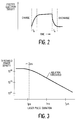
- FIGURE 2 is a diagram showing the excited state electron density of eye tissue at a laser beam interaction point. The diagram shows that the excited state electron density is related to the energy density of the incident laser beam. As photons from a laser beam interact with tissue, the electron state of the molecules undergo “charging" to a steady state. The "charging" time t R is related to the electron migration rate. The discharge time is also equal to t R . The charge/discharge time t R is approximately 0.5 to 1 picoseconds.
- the excited state electron density After the initial photons of a laser pulse charge the excited state electron density to a steady state, the remaining photons of the pulse have essentially no effect on such density.
- the steady state arises because energy migrates away from the beam interaction point.
- the energy migration process is counter-balanced by additional laser beam pumping to build up the critical excited state electron density.
- the excited state orbitals diffuse from the laser interaction point into the depth of the material (along the laser beam direction).
- the excited state distribution curve will have less steep a slope compared to the curve from a shorter pulse.
- the present invention recognizes that the depth of the tissue layer which has sufficient excited state orbitals to satisfy the ablation threshold condition will be correspondingly deepened. Therefore, the damage inflicted by a longer duration laser pulse is more extensive than the damage inflicted with a shorter duration pulse.
- a longer pulse duration is required to achieve sufficient photon interactions to charge the excited state electron density to a steady state.
- a higher energy density is required for a laser pulse having a shorter duration.
- more photon interactions per unit of time occur, thereby more rapidly charging the excited state electron density to the steady state.
- Less energy migrates away from the laser interaction point. Consequently, the total integrated energy of a narrower pulse need not be as great as the total integrated energy of a longer pulse to achieve the ablation threshold.
- FIGURE 3 is a diagram showing eye tissue ablation energy threshold versus pulse width. As the laser pulse width reaches about 2 picoseconds, and the energy density of the beam is about 1.0 ⁇ J/(10 ⁇ m) 2 for an 830 nm wavelength, the number of photons is sufficient to maintain a steady state excited state electron density without significant decay. This relationship between pulse duration and constant ablation threshold has been found to exist from about 2 picoseconds down to at least 0.01 picoseconds. Thus, for example, a 2 picosecond pulse may have about the some ablation threshold as a much shorter pulse.
- ablation can be achieved at a low ablation threshold energy using such extremely short duration laser pulses.
- tissue damage from acoustic shock and kinetic action from dissociated matter is directly proportional to energy deposited at the laser interaction point. If the ablation threshold is achieved at less than the total pulse energy, the remaining energy in the pulse is completely absorbed by the generated plasma, thereby contributing to the explosive effect of the tissue ablation. Both acoustic shock and kinetic action are decreased by reducing the pulse duration.
- FIGURE 4 is a diagram showing the relative diameters of tissue regions removed by laser pulses at the ablation threshold for pulses of approximately 1 nanosecond, 10 picoseconds, and 0.1 picosecond duration. As can be seen, the range of tissue removal and surrounding tissue damage is substantially less for the shorter pulses (the volume of tissue removed is proportional to energy deposited, which falls off from the center of the interaction point proportionally to the radius cubed).
- the illustrated embodiment of the present invention uses an 630 nm wavelength for the laser beam, which is generally transmissive in eye tissue.
- a wavelength can be generated in known fashion from a broad gain bandwidth (i.e., ⁇ > ⁇ 1 mm) laser, such as a Ti:Al 2 O 3 , Cr:LiSrAlF 6 , Nd:YLF, or similar laser.
- a broad gain bandwidth i.e., ⁇ > ⁇ 1 mm
- a Ti:Al 2 O 3 , Cr:LiSrAlF 6 , Nd:YLF, or similar laser is described in U.S. Patent 5 280 491, entitled "Two Dimensional Scanner-Amplifier Laser" and assigned to the assignee of the present invention.
- wavelengths could be used as desired, since absorption and transmission in the eye is a matter of degree.
- less transmissive wavelengths can be used for procedures at or near the front of the eye, such as the cornea.
- acceptable wavelengths include the ranges of about 400 nm to about 1900 nm. about 2.1 ⁇ m to about 2.8 ⁇ m, and longer than about 3.1 ⁇ m.
- FIGURE 5 is a diagram showing the interaction point P of a laser beam.
- the portion of the beam above and below the interaction point P lacks sufficient energy density to ignite photoablation. Hence, those portions of the laser beam pass through the surrounding tissue without causing damage. Where the beam is focused most tightly (i.e., the focal point), the energy density is sufficient to initiate ablation.
- the laser beam cross-sectional area of the invention at the interaction point is preferably about 10 ⁇ m in diameter.
- the preferred beam size of the invention contrasts with current excimer laser surgical systems, which subject an ablation zone to a surgical beam that is typically 4-6 mm in diameter.
- the beam diameter can be varied to any tolerably achievable smaller or larger dimension, as required by the particular type of surgery. In particular, a range of about 1 ⁇ m to about 30 ⁇ m is preferred.
- Each laser pulse of the type described above is preferably directed to its intended location in or on the eye through a laser beam control means, such as the type described in WO-A-9 308 877.
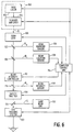
- FIGURE 6 shows a block diagram of such a laser and control system.
- FIGURE 6 shows a laser unit 100 for generating an initial laser beam B.
- the laser unit 100 is of the type that can output a beam rapidly deflectable or scannable under electronic control in two dimensions to any location in an area defined by orthogonal X and Y axes.
- One such laser unit is described in detail in the co-pending, commonly-owned patent application for invention entitled “Two Dimensional Scanner-Amplifier Laser” (U.S. Patent 5 280 491).
- the initial laser beam B comprises a sequence of laser pulses having a pulse repetition rate of about 100 to 100.000 pulses per second.
- the actual number of laser pulses used for a surgery is determined by the amount of tissue to be removed.
- the laser unit 100 includes a seed laser 102 and a scanner-amplifier laser 104.
- the laser media in both the seed laser 102 and the scanner-amplifier 104 is a Ti:Al 2 O 3 solid state laser crystal.
- the laser beam B After emerging from the laser unit 100, the laser beam B passes through a computer-controllable, motorized zoom lens 106, which provides control over the diameter of the laser beam B.
- the zoom lens 106 may be placed in a number of suitable positions along the optical path of the laser beam between the laser unit 100 and a target.
- the motor actuation of the zoom lens 106 may be by any known means, such as electrical gear drives or piezoelectric actuators.
- the entire surgical laser apparatus includes a number of control and safety systems.
- the present invention includes means for monitoring and controlling the intensity of the beam, means for blocking the surgical beam in the event of a malfunction, means for monitoring and controlling the laser beam diameter and intensity profile, and means for verifying the two-dimensional (X-Y) scan position of the surgical beam.
- the laser beam B passes through a beam intensity controller 112, the output of which is the surcical laser beam S.
- the beam intensity controller 112 permits regulation of the energy of each laser pulse so that the etch depth of each pulse may be precisely controlled.
- the beam intensity controller 112 is an electro-optical filter, such as an electrically activated Pockels cell in combination with an adjacent polarizing filter.
- the beam intensity controller 112 is coupled to a computer control unit 114, which is suitably programmed to vary the intensity of the output surgical laser beam S as required for a particular surgical procedure.
- the degree of beam retardation as a function of applied electrical signal can be ascertained by standard calibration techniques.
- the preferred location of the beam intensity control unit 112 is as shown in FIGURE 6. However, the beam intensity control unit 112 can be placed at several suitable locations in the beam path between the laser unit 100 and a target.
- the intensity of the surgical beam S is regulated to have an ablation energy density of less than or equal to about 5 ⁇ J/(10 ⁇ m) 2 .
- the present invention optionally provides for positive feed-back measurement of the beam intensity.
- a partially transmissive beam-splitting mirror 116 is placed after the beam intensity controller 112, and the reflected beam R i is directed to a beam intensity sensor 118.
- the beam intensity sensor 118 may be simply a photocell, although other elements, such as focussing optics, may be included.
- the intensity of the surgical laser beam S can be positively measured to verify the proper operation of the beam intensity controller 112.
- the output of the beam intensity sensor 118 as a function of intensity of the surgical laser beam S can be ascertained by standard calibration techniques.
- the inventive system also preferably includes a safety shutter 120, which is coupled to the computer control unit 114.
- the safety shutter 120 may be, for example, a mechanically-actuated shutter operated in a "fail-safe" mode.
- the safety shutter 120 may include a solenoid-actuated shield that is positively held open by application of electrical energy to the solenoid. Upon command of the computer control unit 114, or failure of the entire system, electrical energy to the solenoid is cut off, causing the solenoid to retract the shield into position to block the path of the surgical laser beam S.
- the safety shutter 120 is also useful for temporarily blocking the laser beam S while changing the position of the patient's eye or of the beam itself, without turning the laser beam S completely off.
- the safety shutter 120 may include a Pockels cell and polarizer configured as a light valve, with the Pockels cell biased with respect to the polarizer by application of an electrical voltage such that maximum light is normally transmitted by the combination. Cessation of the applied voltage will cause the output of the Pockels cell to become polarized orthogonal to the transmission direction of the polarizer, hence blocking the surgical laser beam S.
- the safety shutter 120 and the beam intensity controller 112 may be combined into a single unit.
- any other suitable means for quickly blocking the surgical laser beam S on command or in the event of system failure may be used to implement the safety shutter 120.
- the safety shutter 120 may be placed in a number of suitable positions along the optical path of the laser beam between the laser unit 100 and a target.
- the inventive system provides a partially transmissive beam-splitting mirror 122 that reflects part of the beam R d to a beam diameter sensor 124.
- the beam diameter sensor 124 may be placed in a number of suitable positions along the optical path of the laser beam between the laser unit 100 and a target.
- the beam diameter sensor 124 preferably includes at least a diverging (concave) lens and a converging (convex) lens configured as a magnifying telescope (i.e., the two lenses have a common focal point, with the focal length f 2 of the converging lens being greater than the focal length f 1 of the diverging lens, and having optical centers aligned with the incident laser beam in its un-deflected position).
- the incident beam R d enters the diverging lens and exits the converging lens.
- Such a configuration of lenses, while enlarging the incident beam will also reduce the scan angle of the exiting beam.
- the resulting enlarged beam is directed to a high sensitivity, low contrast imaging device, such as a charge-coupled device (CCD) camera.
- CCD charge-coupled device
- the converging and diverging lenses are chosen to expand the incident beam R d so that the largest possible diameter for the beam just fits within the imaging device.
- the size of the beam is determined by periodically addressing a central row and a central column of the imaging device and counting the number of pixels on each sampled axis that have been illuminated. By comparing the diameter of the beam in both the X and Y directions, the beam diameter sensor can determine whether the incident laser beam B is approximately circular and has the desired diameter.
- the beam diameter sensor 124 can also be used to determine the intensity profile of the laser pulses, since each pixel in the beam diameter sensor 124 can generate an output indicative of the intensity of light incident to the pixel. By comparing pixel values from radially symmetric points in the pixel array, it can be determined if an incident laser pulse or series of pulses has the desired radially symmetric intensity profile, or if the pulses have developed "hot spots" of out-range intensity values.
- the output of the beam diameter sensor 124 is coupled to the computer control unit 114.
- the computer control unit 114 is in turn coupled to the motorized zoom lens 106, which provides control over the diameter of the laser beam B.
- the computer control unit 114 is suitably programmed to vary the diameter of the laser beam as required for a particular surgical procedure.
- the output of the beam diameter sensor 124 as a function of beam diameter can be ascertained by standard calibration techniques.
- This configuration provides positive feed-back of the beam diameter emanating from the laser unit 100. If the beam diameter sensor 124 detects an out-of-range beam (either diameter or intensity profile), the computer control unit 114 can take appropriate action, including activation of the safety shutter 120.
- the inventive system provides a partially transmissive beam-splitting mirror 126 that reflects part of the beam energy R I to a beam location sensor 128.
- the beam location sensor 128 preferably includes at least a converging (convex) lens and a diverging (concave) lens configured as a reducing telescope (i.e., the two lenses have a common focal point, with the focal length f 2 of the diverging lens being greater than the focal length f 1 of the converging lens, and having optical centers aligned with the incident laser beam in its un-deflected position).
- the incident beam R I enters the converging lens and exits the diverging lens.
- Such a configuration of lenses, while reducing the incident beam will also increase the scan angle of the exiting beam.
- the resulting increased-scan angle beam is directed to a silicon photo-detector, such as the position sensing detector, model DLS-20 manufactured by UDT Sensors, Inc. of Hawthorne, CA.
- the photo-detector provides a voltage reading with respect to the two-dimensional (X-Y) position of an illuminating spot at the detector surface.
- the output of the beam location sensor 128 is coupled to the computer control unit 114. Calibration of the voltage reading generated from the un-deflected incident beam position on the photo-detector will indicate the origin of the laser beam in the XY-scan plane. Any deflection of the beam from the origin will generate voltage readings indicative of the spot on the photo-detector surface illuminated by the laser beam.
- These voltage readings are calibrated against the indicated location of the surgical beam as set by the computer control unit 114.
- the output of the beam location sensor 128 would be sampled periodically (for example, about 1,000 times per second) and compared to a prepared calibration table in the computer control unit 114 to determine if the actual beam position matches the indicated position.
- This configuration provides positive feed-back of the beam position emanating from the laser unit 100. If the beam location sensor 128 detects an out-of-position beam, the computer control unit 114 can take appropriate action, including activation of the safety shutter 120.
- the preferred embodiment of the inventive surgical laser apparatus provides for safe and effective surgery by continuously monitoring all aspects of the condition of the surgical laser beam S, including beam intensity, diameter, and X-Y scan position.
- an eye tracking system 130 is placed in the path of the surgical laser beam S, preferably in close proximity to a target eye.
- the eye tracking system 130 monitors movement of a patient's eye and adjusts the position of the surgical laser beam S to compensate. Such tracking may be accomplished by providing fiducial marks on the eye and optically tracking movement of said fiducial marks. Deflectable mirrors may then be used to steer the surgical laser beam S.
- An example of one such system is described in WO-A-9 308 877.
- the present invention includes a guide beam unit 132.
- the guide beam unit 132 includes a low-power laser with an output of preferably less than 1 milliwatt at initial output and preferably attenuated to the microwatt level for safe usage for direct viewing.
- the low-power laser generates a guide beam which is conditioned optically so that it is aligned with the surgical laser beam S and can be used as a indicator of the location of the surgical laser beam S.
- the guide beam can be used as an element for the alignment of a patient's eye in preparation for surgical procedures.
- the laser surgical system of the present invention can perform numerous types of surgical procedures on the eye.
- the focal point of the surgical laser beam S is placed a known reference location, preferably in the vicinity of the point of surgery.
- the eye tracking system 130 is activated. Any eye movement thereafter will be compensated for by a corresponding automatic adjustment of the laser beam position.
- the inventive system can perform any and all of the following procedures:
- the present invention is useful for performing surgical procedures to correct glaucoma by creating a one or more openings through an iris to release fluids from the posterior chamber which create undesirable pressure behind the cornea.
- one or more excisions may be created in the posterior or anterior capsule to permit removal of material from the capsule and to implant an intraocular lens (IOL) or any other lens-like material or structure which can be in fluid or gel form.
- IOL intraocular lens
- a cataractal lens can be ablated and liquified.
- the inventive procedure can be used prior to an IOL implant for cataract conditioning.
- portions of the retinal membrane which create tension on the retina may be cut to relieve such tension.
- portions of the retina may be operated upon to remove harmful tissue. Accordingly, the invention precisely controls and determines the location of the interaction point of a surgical laser beam and controls the shape of the cornea during ophthalmic surgery.
- a ophthalmic surgical laser system which can be adapted for use with the present invention to provide for precisely controlling and determining the location of the interaction point of a surgical laser beam, and for controlling the shape of the cornea during ophthalmic surgery, is set forth in U.S. Patent 5 549 632, entitled “METHOD AND APPARATUS FOR OPHTHALMIC SURGERY".
- a transparent applanator plate is placed in contact with the cornea of a patient's eye.
- the applanator plate creates a fixed positional frame of reference from which a laser beam control system can determine the desired point or points at which to focus the surgical laser beam, and thereby direct an interaction point of the beam to very precisely defined locations within the patient's eye.
- the surface of the applanator plate in contact with the patient's eye can be planar, concave, or convex, with either a spheric or aspheric curvature, a compound curve, or any other shape chosen by the surgeon. Applying the applanator plate to the cornea of the patient's eye causes the cornea to conform to the shape of the applanator plate.
- FIGURE 14A shows a cross-sectional side view of a convex applanator plate 111.
- the applanator plate 111 has at least two surfaces, a tip surface 109 and a corneal surface 113.
- the applanator plate 111 is placed in contact with the corneal epithelium 115 and deforms the cornea to conform to the convex shape of the corneal surface 113.
- FIGURE 14B shows a cross-sectional side view of a concave applanator plate 111' applied to an eye.
- the applanator plate 111' is placed in contact with the corneal epithelium 115 and deforms the cornea to conform to the concave shape of the corneal surface 113'.
- a surgical tip at the distal end of an articulated arm (not shown) having flexible joints is placed in contact with the tip surface 109 of the applanator plate 111, 111' and follows any motion of the patient's eye.
- the articulated arm is coupled to a surgical laser source including a laser beam control system, such as the system described in co-pending patent applications filed by the present inventor for inventions entitled “Two Dimensional Scanner-Amplifier Laser” (U.S. Patent Application Serial No. 5 280 491). and “Method of, and Apparatus for Surgery of the Cornea” (WO-A-9 308 877).
- the surgical laser source also includes the source of the laser beam.
- the articulated arm directs the laser beam to the surgical tip, translating the motion of the beam relative to a reference frame fixed to the surgical laser source to a reference frame fixed with respect to the applanator plate to which the surgical tip is in contact. Since the shape of the cornea conforms to the contour of corneal surface 113, 113' of the applanator plate 111, 111' incisions of various shapes can be made by selecting an appropriate applanator plate and controlling the surgical beam to move linearly with respect to the fixed frame by the applanator plate.
- the applanator plate 111, 111' also provides a means to control the contour of the index of refraction boundary between the corneal epithelium 115 of the patient's eye and the air. Controlling the contour of this boundary reduces the distortion of the surgical laser beam which would otherwise be present due to the curvature of the outer surface of the epithelium and the difference in the index of refraction between the air and the stroma underlying the epithelium.
- the index of refraction of the applanator plate is preferably closely matched to the index of refraction of the cornea (i.e., index of approximately 1.38). i he tip surface 112 of the applanator plate 111, 111' is selectively shaped to provide a desirable contour at the boundary between the index of refraction of the stroma and air.
- the applanator plate 111, 111' serves at least three purposes: (1) to provide a positional (x, y, z) reference for a surgical laser; (2) to control the shape of the patient's cornea during a surgical laser procedure; and (3) to provide a boundary between the epithelium and air, the contour of which can be controlled to reduce the distortion of the surgical laser beam.
- the applanator plate 111, 111' provides even greater control of tissue removal.
- the preferred procedure of performing a surface ablation of cornea tissue or other organic materials uses a laser source which has the characteristics of providing a shallow ablation depth or region (about 0.2 ⁇ m to about 5.0 ⁇ m), a low ablation energy density threshold (about 0.2 to 5 ⁇ J/(10 ⁇ m) 2 , and extremely short laser pulses (having a duration of about 0.01 picoseconds to about 2 picoseconds per pulse) to achieve precise control of tissue removal.
- the laser beam cross-sectional area is preferably about 10 ⁇ m in diameter.
- the preferred laser system includes a broad gain bandwidth laser, such as Ti:Al 2 O 3 , Cr:LiSrAlF 6 , Nd:YLF, or similar lasers, with a preferred wavelength range of about 400 nm to about 1900 nm, which is generally transmissive in eye tissue.
- a broad gain bandwidth laser such as Ti:Al 2 O 3 , Cr:LiSrAlF 6 , Nd:YLF, or similar lasers, with a preferred wavelength range of about 400 nm to about 1900 nm, which is generally transmissive in eye tissue.
- the surgical beam can be directed to remove cornea tissue in a predetermined amount and at a predetermined location such that the cumulative effect is to remove defective or non-defective tissue, or to change the curvature of the cornea to achieve improved visual acuity.
- Excisions on the cornea can be made in any predetermined length and depth, and in straight line or in curved patterns.
- circumcisions of tissue can be made to remove an extended area, as in a cornea transplant.
- the invention can be used to excise or photoablate regions within the cornea, capsule, lens, vitreoretinal membrane, and other structures within the eye.
- the present invention provides an improved apparatus for performing eye surgery which has accurate control of tissue removal, flexibility of ablating tissue at any desired location with predetermined ablation depth, an optically smooth finished surface after the surgery, and a gentle surgical beam for laser ablation action.
Landscapes
- Optics & Photonics (AREA)
- Physics & Mathematics (AREA)
- Health & Medical Sciences (AREA)
- Engineering & Computer Science (AREA)
- Ophthalmology & Optometry (AREA)
- Life Sciences & Earth Sciences (AREA)
- Veterinary Medicine (AREA)
- Biomedical Technology (AREA)
- Heart & Thoracic Surgery (AREA)
- Vascular Medicine (AREA)
- Nuclear Medicine, Radiotherapy & Molecular Imaging (AREA)
- Animal Behavior & Ethology (AREA)
- General Health & Medical Sciences (AREA)
- Public Health (AREA)
- Surgery (AREA)
- Plasma & Fusion (AREA)
- Mechanical Engineering (AREA)
- Laser Surgery Devices (AREA)
- Lasers (AREA)
- Laser Beam Processing (AREA)
- Treatments Of Macromolecular Shaped Articles (AREA)
- Manufacture Of Macromolecular Shaped Articles (AREA)
- Materials For Medical Uses (AREA)
Abstract
Description
- This invention relates to apparatus for eye surgery, and more particularly to a laser-based apparatus for corneal and intraocular surgery.
- The concept of correcting refractive errors by changing the curvature of the eye was initially implemented by mechanical methods. These mechanical procedures involve removal of a thin layer of tissue from the cornea by a microkeratome, freezing the tissue at the temperature of liquid nitrogen, and re-shaping the tissue in a specially designed lathe. The thin layer of tissue is then re-attached to the eye by suture. The drawback of these methods is the lack of reproducibility and hence a poor predictability of surgical results.
- With the advent of lasers, various methods for the correction of refractive errors and for general eye surgery have been attempted, making use of the coherent radiation properties of lasers and the precision of the laser-tissue interaction. A CO2 laser was one of the first to be applied in this field. Peyman, et al., in Ophthalmic Surgery, vol. 11, pp. 325-9, 1980, reported laser burns of various intensity, location, and pattern were produced on rabbit corneas. Recently, Horn, et al., in the Journal of Cataract Refractive Surgery, vol. 16, pp. 611-6, 1990, reported that a curvature change in rabbit corneas had been achieved with a Co:MgF2 laser by applying specific treatment patterns and laser parameters. The ability to produce burns on the cornea by either a CO2 laser or a Co:MgF2 laser relies on the absorption in the tissue of the thermal energy emitted by the laser. Histologic studies of the tissue adjacent to burn sites caused by a CO2 laser reveal extensive damage characterized by a denaturalized zone of 5-10 µm deep and disorganized tissue region extending over 50 µm deep. Such lasers are thus ill-suited to eye surgery.
- In U.S. Patent No. 4,784,135, Blum et al. discloses the use of far-ultraviolet excimer laser radiation of wavelengths less than 200 nm to selectively remove biological materials. The removal process is claimed to be by photoetching without using heat as the etching mechanism. Medical and dental applications for the removal of damaged or unhealthy tissue from bone, removal of skin lesions, and the treatment of decayed teeth are cited. No specific use for eye surgery is suggested, and the indicated etch depth of 150 µm is too great for most eye surgery purposes.
- In U.S. Patent No. 4,718,418, L'Esperance, Jr. discloses the use of a scanning ultraviolet laser to achieve controlled ablative photodecomposition of one or more selected regions of a cornea. According to the disclosure, the laser beam from an excimer laser is reduced in its cross-sectional area, through a combination of optical elements, to a 0.5 mm by 0.5 mm rounded-square beam spot that is scanned over a target by deflectable mirrors. To ablate a corneal tissue surface with such an arrangement, each laser pulse would etch out a square patch of tissue. An etch depth of 14 µm per pulse is taught for the illustrated embodiment. This etch depth would be expected to result in an unacceptable level of eye damage.
- Another technique for tissue ablation of the cornea is disclosed in U.S. Patent No. 4,907,586 to Bille et al. By focusing a laser beam into a small volume of about 25-30 µm in diameter, the peak beam intensity at the laser focal point could reach about 1012 watts per cm2. At such a peak power level, tissue molecules are "pulled" apart under the strong electric field of the laser light, which causes dielectric breakdown of the material. The conditions of dielectric breakdown and its applications in ophthalmic surgery had been described in the book "YAG Laser Ophthalmic Microsurgery" by Trokel. Transmissive wavelengths near 1.06 µm and a frequency-doubled laser wavelength near 530 nm are typically used for the described method. Near the threshold of the dielectric breakdown, the laser beam energy absorption characteristics of the tissue changes from highly transparent to strongly absorbent. The reaction is very violent, and the effects are widely variable. The amount of tissue removed is a highly non-linear function of the incident beam power. Hence, the tissue removal rate is difficult to control. Additionally, accidental exposure of the endothelium by the laser beam is a constant concern. This method is not optimal for cornea surface or intraocular ablation.
- US Patent No. 4,988,348 Bille et al describes a method for reshaping the cornea using a pulsed Nd:YLF or erbium laser having wavelengths of 0.527 µm or 2.94 µm and an energy density sufficient to cause photoablation of corneal tissue near the threshold of the plasma regime. Squier & Mourou in Laser Focus World, June 1992, pages 51-60, describe a chirped-laser formed of Ti:AL203 which is capable of producing 100 fs pulses. Stern et al in Arch. Ophthalmol., April 1989, volume 107, pages 587-592, describe experiments using lasers having nanosecond, picosecond and femtosecond width pulses for use in corneal ablation. The article describes additional damage that occurs to eye tissues with pulses of 1 ps or less duration and concludes that picosecond lasers (i.e. those having a pulse duration of greater than 1 ps) appear most promising for use in corneal ablation surgery.
- An important issue that is largely overlooked in all the above-cited references is the fact that the eye is a living organism. Like most other organisms, eye tissue reacts to trauma, whether it is inflicted by a knife or a laser beam. Clinical results have shown that a certain degree of haziness develops in most eyes after laser refractive surgery with the systems taught in the prior art. The principal cause of such haziness is believed to be roughness resulting from cavities, grooves, and ridges formed while laser etching. Additionally, clinical studies have indicated that the extent of the haze also depends in part on the depth of the tissue damage, which is characterized by an outer denatured layer around which is a more extended region of disorganized tissue fibers. Another drawback due to a rough corneal surface is related to the healing process after the surgery: clinical studies have confirmed that the degree of haze developed in the cornea correlates with the roughness at the stromal surface.
- The prior art also fails to recognize the benefits of ablating eye tissue with a laser beam having a low energy density. A gentle laser beam, one that is capable of operating at a lower energy density for a surgical procedure, will clearly have the advantage of inflicting less trauma to the underlying tissue. The importance of this point can be illustrated by considering the dynamics of the ablation process on a microscopic scale: the ablation process is basically an explosive event. During ablation, organic materials are broken into their smaller sub-units, which cumulate a large amount of kinetic energy and are ejected away from the laser interaction point at a supersonic velocity. The tissue around the ablated region absorbs the recoil forces from such ejections. The tissue is further damaged by acoustic shock from the expansion of the superheated plasma generated at the laser interaction point. Accordingly, a shallower etch depth or smaller etch volumes involves less ejected mass and acoustic shock, and hence reduces trauma to the eye.
- It is therefore desirable to have an apparatus for performing eye surgery that overcomes the limitations of the prior art. In particular, it is desirable to enable eye surgery which has accurate control of tissue removal, flexibility of ablating tissue at any desired location with predetermined ablation depth or volume, an optically smooth finished surface after the surgery, and a gentle surgical beam for laser ablation action.
- The present invention provides such an apparatus.
- According to the present invention there is provided a pulsed laser apparatus for providing controlled ablation of organic material at a selected point of interaction by means of generated laser pulses, the apparatus including a laser for emitting a beam of pulses having a duration in a range of about 0.01 picoseconds to about 2 picoseconds, and the apparatus being characterised by means for monitoring the diameter of the cross-sectional area of the laser pulses, and means responsive to the diameter monitoring means to control the said diameter.
- The present invention recognises that an optically smooth corneal surface and a clear intraocular light path (including post operative clarity) are all critical to successful ophthalmic surgery. The effects of eye surgery on all of the intraocular elements encountered by light traversing the optical path from the cornea to the retina must be considered. The invention was developed with a particular view to preserving these characteristics.
- The preferred method of performing a surface ablation of cornea tissue or other organic materials uses a laser source which has the characteristics of providing a shallow ablation depth or region (about 0.2 µm to about 5.0 µm) and a low ablation energy density threshold (about 0.2 to 5µJ/(10µm)2). The duration of laser pulses allows precise control of tissue removal to be achieved. The laser beam cross sectional area is preferably about 10 µm in diameter. This method does not constitute a portion of the invention and is described for illustrative purposes only.
- The laser system may include a broad gain bandwidth laser, such as a Ti3Al2O3, Cr:LiSrAlF6, Nd:YLF or similar lasers with a preferred wavelength of about 400nm to about 1900nm, which is generally tansmissive in eye tissue.
- Each laser pulse may be directed to its intended location in or on the eye through a laser beam control means, such as the type described in "Method of, and Apparatus for, Surgery of the Cornea" (WO-A-9308877).
- Various surgical procedures can be performed to correct refractive errors or to treat eye diseases. The surgical beam can be directed to remove cornea tissue in a predetermined amount and at a predetermined location such that the cumulative effect is to remove defective or non-defective tissue, or to change the curvature of the cornea to achieved improved visual acuity. Excisions on the cornea can be made in any predetermined length or depth, and in straight line or curved patterns. Alternatively, circumcisions of tissue can be used to excise or photoablate regions within the cornea, capsule, lens, vitreoretinal membrane, and other structures within the eye.
- The present invention can be used in a method of eye surgery which has accurate control of tissue removal, flexibility of ablating tissue at any desired location with predetermined ablation depth, an optically smooth finished surface after the surgery, and a gentle surgical beam for laser ablation action.
- The details of the preferred embodiments of the present invention are set forth in the accompanying drawing and the description below. Once the details of the invention are known, numerous additional innovations and changes will become obvious to one skilled in the art.
-
- FIGURE 1A is a diagram showing the power density of a square laser pulse versus time for a 5 ns pulse.
- FIGURE 1B is a diagram showing the power density of a square laser pulse versus time for a 2.5 ns pulse.
- FIGURE 2 is a diagram showing the excited state electron density of eye tissue at a laser beam interaction point.
- FIGURE 3 is a diagram showing eye tissue ablation energy threshold versus pulse width.
- FIGURE 4 is a diagram showing the relative diameters of tissue regions removed by laser pulses at the ablation threshold for pulses of approximately 1 ns, 10 ps, and 1 ps duration.
- FIGURE 5 is a diagram showing the interaction point of a laser beam.
- FIGURE 6 is a block diagram of the preferred embodiment of the inventive apparatus.
- FIGURE 7 is a cross-sectional side view of a cornea showing some of the resulting incisions which can be formed in a stroma by the present invention.
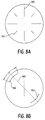
- FIGURE 8A is a top view of a cornea, showing the use of the present invention to make radial excisions on the cornea.
- FIGURE 8B is a top view of a cornea, showing the use of the present invention to make transverse-cut excisions on the cornea.
- FIGURE 9A and 9B are cross-sectional side views of a cornea, showing the use of the present invention to remove tissue to a desired depth d over an area on the cornea, and an alternative method for performing a cornea transplant.
- FIGURE 10 is a cross-sectional side view of a cornea, showing the use of the present invention to correct myopia.
- FIGURE 11 is a cross-sectional side view of a cornea, showing the use of the present invention to correct hyperopia.
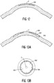
- FIGURE 12 is a cross-sectional side view of a cornea, showing the use of the present invention to correct myopia using an alternative method.
- FIGURE 13A is a cross-sectional side view of a cornea, showing the use of the present invention to correct hyperopia using an alternative method.
- FIGURE 13B is a top view of the cornea of FIGURE 13A, showing the use of the perimeter radial cuts to help correct hyperopia.
- FIGURE 14A is a cross-sectional side view of a convex applanator plate applied to an eye.
- FIGURE 14B is a cross-sectional side view of a concave applanator plate applied to an eye.
-
- Like reference numbers and designations in the various drawings refer to like elements.
- Throughout this description, the preferred embodiment and examples shown should be considered as exemplars, rather than limitations on the apparatus of the present invention.
- The laser apparatus disclosed in this invention is for achieving two principal objectives:
- (1) The damage zone around the material ablated by the inventive laser system must be substantially reduced in comparison to prior art laser Systems.
- (2) For each laser pulse deposited in or on the eye, a definite predetermined depth or volume of tissue is to be ablated. The ablated depth per laser pulse must be controllable and about 5 µm or less, and preferably about 0.5 µm or less.
-
- To achieve these objectives, the present invention uses short duration laser pulses from about 0.01 to 2 picoseconds to reduce inflicted damage to target tissues. The preferred laser system includes a Ti:Al2O3, Cr:LiSrAlF6, Nd:YLF, or similar laser with a preferred wavelength of about 400 nm to about 1900 nm. The laser beam cross-sectional area is preferably about 10 µm in diameter. The importance of these characteristics is explained below.
- A fundamental problem of prior art ophthalmic surgical laser systems is that such systems fail to adequately take into account the interaction of the laser beam with organic tissue in the ablation process, particularly when using relatively transmissive laser wavelengths. Laser ablation occurs when the laser beam intensity, or energy level, is increased beyond a certain threshold level, causing dielectric breakdown. However, the actual ablation conditions vary depending on the characteristics of a wide range of laser parameters and the composition of the material to be ablated. When laser energy is absorbed in an organic material, on the most basic level, the electronic configuration of the target polymer molecules makes a transition to one of its excited electronic states. Each polymer is made of hundreds or more of sub-units of smaller molecules called monomers. The monomers are made of even smaller units of radicals consisting of combinations of hydrogen, carbon, oxygen, and nitrogen atoms. Depending on the energy level of the laser photons, a polymer can be broken into constituent monomers, radicals, or ionized atoms.
- For a laser having a wavelength near about 830 nm, a single laser photon is not sufficiently energetic to break any molecular bond. Breaking such a bond is a highly non-linear multi-photon process. After absorbing an initial photon, a molecule is promoted to an excited electronic state configuration, with its electrons in higher energy orbits. This state will decay, or "relax", if additional photons are not absorbed to maintain the excited electronic state configuration.
- As the laser beam intensity increases further towards the ablation threshold, additional photons are absorbed, and the excited electron density reaches a critical volume density such that the electronic orbitals can pair and transfer the sum of their energy to a single electron orbital. This process breaks the molecule into two or more pieces, and releases an energetic electron. At this point, the organic medium is damaged but not yet ablated.
- With increased power levels of the laser beam, further photons are absorbed, and the excited electron density increases correspondingly. At the same time, the excited electrons migrate down the polymeric chain of the organic material, and spread towards the bulk volume with lower excited state density. The present invention recognizes that the excited state electronic orbitals are the means for energy storage that will eventually fuel the ablation process, and the electronic energy state migration process plays a key role in the dynamics controlling the initiation of the laser ablation.
- Because photoablation requires multiple photons interacting with organic tissue molecules, "ignition" of ablative action near the threshold condition is determined by a statistical process. That is, determination of the average etch depth or volume for laser beam energies near the ablation energy threshold are derived by measuring actual etch depth or volume after hundreds or sometimes thousands of laser pulses over the same location, and determining an average etch amount per pulse. On a single shot basis, however, the etch depth or volume could vary significantly, and most of the laser pulses may not ablate any material at all. In general, the ablation threshold for a particular wavelength is the total integrated energy required for 50% of laser pulses to have an effect.
- Because of the statistical nature of laser pulse ablation, it is important to note that a reproducible etch depth or volume will not necessarily be attained at reduced levels of laser energy per pulse, especially when the energy level is close to being at an arbitrarily small value above the ablation energy threshold. Thus, in order to ensure a reliable etch depth or etch volume for each single laser pulse, the operating energy per pulse is conventionally set at a multiple of the ablation energy threshold level; a factor of 3 to 4 times the ablation energy threshold is usually considered sufficient to achieve satisfactory results. For an excimer laser, the ablation threshold level is at about 50 mJ/cm2; basically no ablative action is observed at a laser energy density below this threshold level. Accordingly, the typical energy density in an excimer surgical laser beam required for cornea ablation is about 150-250 mJ/cm2.
- Consider now the geometric distribution of the excited state orbitals in an organic material. As the laser light is absorbed in the organic material, by Beer's law, the front surface where the material is first exposed encounters most of the laser photons, and the beam intensity decreases exponentially as it traverses deeper into the material. Hence, the spatial distribution of the excited state density also decreases accordingly, characteristic of the absorption coefficient of the material at the laser wavelength. It follows that the slope of the distribution curve of the excited state electron density is directly related to the absorption coefficient. Additionally, the steeper the slope of the excited state density distribution curve, the more spatially localized is the excited state density.
- Thus, to maintain a small laser beam interaction point (e.g., about 1 µm to about 30 µm, and preferably about 10 µm), the slope of the excited state density distribution curve must be steep. To obtain a steep slope, the pulse width of the impinging laser beam should be kept narrow.
- It is known that if ablation is found to occur at a particular laser peak power, narrowing the laser pulse increases the ablation threshold. For example, FIGURE 1A is a diagram showing the power density of a square laser pulse versus time for a 5 ns pulse. If the ablation threshold is found to occur at a particular power density (arbitrarily considered to have a value of "1" in FIGURE 1), then a higher ablation threshold is required when the pulse is narrowed. That is, the total integrated energy of the shorter laser pulse must approach the total integrated energy of the longer laser pulse. However, it is also known that halving the pulse duration does not require a doubling of the power density of the pulse. For example, FIGURE 1B is a diagram showing the power density of a square laser pulse versus time for a 2.5 ns pulse. The ablation threshold is less than twice the ablation threshold of a 5 ns pulse.
- Empirical results obtained from materials damage indicate that a particular ablation threshold can be reached with a
pulsed laser beam 100 times shorter in duration than a longer duration pulse when the total integrated energy of the shorter laser pulse is at about 10% of the total integrated energy of the longer pulse. - Conventional teaching requires an increase in the ablation threshold energy density as pulse widths are decreased. However, it has been recognized in the present invention that the reason halving the pulse width of a laser does not require a doubling of the ablation threshold energy density is related to the build-up and relaxation of the excited state electron density. FIGURE 2 is a diagram showing the excited state electron density of eye tissue at a laser beam interaction point. The diagram shows that the excited state electron density is related to the energy density of the incident laser beam. As photons from a laser beam interact with tissue, the electron state of the molecules undergo "charging" to a steady state. The "charging" time tR is related to the electron migration rate. The discharge time is also equal to tR. The charge/discharge time tR is approximately 0.5 to 1 picoseconds.
- After the initial photons of a laser pulse charge the excited state electron density to a steady state, the remaining photons of the pulse have essentially no effect on such density. The steady state arises because energy migrates away from the beam interaction point. When using longer duration pulses, the energy migration process is counter-balanced by additional laser beam pumping to build up the critical excited state electron density. However, with a longer laser pulse, the excited state orbitals diffuse from the laser interaction point into the depth of the material (along the laser beam direction). Hence, the excited state distribution curve will have less steep a slope compared to the curve from a shorter pulse. The present invention recognizes that the depth of the tissue layer which has sufficient excited state orbitals to satisfy the ablation threshold condition will be correspondingly deepened. Therefore, the damage inflicted by a longer duration laser pulse is more extensive than the damage inflicted with a shorter duration pulse.
- As noted above, for a laser pulse having a low energy density, a longer pulse duration is required to achieve sufficient photon interactions to charge the excited state electron density to a steady state. Conversely, for a laser pulse having a shorter duration, a higher energy density is required. However, because of the higher energy density, more photon interactions per unit of time occur, thereby more rapidly charging the excited state electron density to the steady state. Less energy migrates away from the laser interaction point. Consequently, the total integrated energy of a narrower pulse need not be as great as the total integrated energy of a longer pulse to achieve the ablation threshold.
- Importantly, it has been discovered in the present invention that the power density for the ablation threshold reaches an approximately constant level as the laser pulse width decreases and closely approaches the charge/discharge time tR. FIGURE 3 is a diagram showing eye tissue ablation energy threshold versus pulse width. As the laser pulse width reaches about 2 picoseconds, and the energy density of the beam is about 1.0 µJ/(10µm)2 for an 830 nm wavelength, the number of photons is sufficient to maintain a steady state excited state electron density without significant decay. This relationship between pulse duration and constant ablation threshold has been found to exist from about 2 picoseconds down to at least 0.01 picoseconds. Thus, for example, a 2 picosecond pulse may have about the some ablation threshold as a much shorter pulse.
- Thus, ablation can be achieved at a low ablation threshold energy using such extremely short duration laser pulses. Further, tissue damage from acoustic shock and kinetic action from dissociated matter is directly proportional to energy deposited at the laser interaction point. If the ablation threshold is achieved at less than the total pulse energy, the remaining energy in the pulse is completely absorbed by the generated plasma, thereby contributing to the explosive effect of the tissue ablation. Both acoustic shock and kinetic action are decreased by reducing the pulse duration.
- Another benefit from reducing the pulse duration is limitation of damage to tissue surrounding the laser interaction point due to energy migration. FIGURE 4 is a diagram showing the relative diameters of tissue regions removed by laser pulses at the ablation threshold for pulses of approximately 1 nanosecond, 10 picoseconds, and 0.1 picosecond duration. As can be seen, the range of tissue removal and surrounding tissue damage is substantially less for the shorter pulses (the volume of tissue removed is proportional to energy deposited, which falls off from the center of the interaction point proportionally to the radius cubed).
- In order to perform intraocular surgical procedures, the laser beam necessarily must pass through overlying tissue to the desired location without damage to the overlying tissue. Accordingly, the illustrated embodiment of the present invention uses an 630 nm wavelength for the laser beam, which is generally transmissive in eye tissue. Such a wavelength can be generated in known fashion from a broad gain bandwidth (i.e., Δλ > ~1 mm) laser, such as a Ti:Al2O3, Cr:LiSrAlF6, Nd:YLF, or similar laser. One such laser is described in U.S. Patent 5 280 491, entitled "Two Dimensional Scanner-Amplifier Laser" and assigned to the assignee of the present invention.
- Other wavelengths could be used as desired, since absorption and transmission in the eye is a matter of degree. Thus, less transmissive wavelengths can be used for procedures at or near the front of the eye, such as the cornea. In general, acceptable wavelengths include the ranges of about 400 nm to about 1900 nm. about 2.1 µm to about 2.8 µm, and longer than about 3.1 µm.
- Because of the preferred transmissivity of the laser beam, and the requirement that a threshold energy density be achieved to ignite ablation, the interaction "point" (it is actually a generally planar region) of the laser beam can be focused quite tightly. FIGURE 5 is a diagram showing the interaction point P of a laser beam. The portion of the beam above and below the interaction point P lacks sufficient energy density to ignite photoablation. Hence, those portions of the laser beam pass through the surrounding tissue without causing damage. Where the beam is focused most tightly (i.e., the focal point), the energy density is sufficient to initiate ablation.
- Another way to reduce the shock to the eye is by using a smaller beam area at the interaction point to reduce the integrated recoil forces. Consequently, the laser beam cross-sectional area of the invention at the interaction point is preferably about 10µm in diameter. The preferred beam size of the invention contrasts with current excimer laser surgical systems, which subject an ablation zone to a surgical beam that is typically 4-6 mm in diameter.
- The beam diameter can be varied to any tolerably achievable smaller or larger dimension, as required by the particular type of surgery. In particular, a range of about 1 µm to about 30 µm is preferred.
- Each laser pulse of the type described above is preferably directed to its intended location in or on the eye through a laser beam control means, such as the type described in WO-A-9 308 877. FIGURE 6 shows a block diagram of such a laser and control system.
- More particularly, FIGURE 6 shows a
laser unit 100 for generating an initial laser beam B. Thelaser unit 100 is of the type that can output a beam rapidly deflectable or scannable under electronic control in two dimensions to any location in an area defined by orthogonal X and Y axes. One such laser unit is described in detail in the co-pending, commonly-owned patent application for invention entitled "Two Dimensional Scanner-Amplifier Laser" (U.S. Patent 5 280 491). - The initial laser beam B comprises a sequence of laser pulses having a pulse repetition rate of about 100 to 100.000 pulses per second. The actual number of laser pulses used for a surgery is determined by the amount of tissue to be removed.
- In a preferred embodiment, the
laser unit 100 includes aseed laser 102 and a scanner-amplifier laser 104. Preferably the laser media in both theseed laser 102 and the scanner-amplifier 104 is a Ti:Al2O3 solid state laser crystal. - After emerging from the
laser unit 100, the laser beam B passes through a computer-controllable,motorized zoom lens 106, which provides control over the diameter of the laser beam B. In practice, thezoom lens 106 may be placed in a number of suitable positions along the optical path of the laser beam between thelaser unit 100 and a target. The motor actuation of thezoom lens 106 may be by any known means, such as electrical gear drives or piezoelectric actuators. - While the laser beam B could be used directly for surgical purposes, in the preferred embodiment, the entire surgical laser apparatus includes a number of control and safety systems. In particular, the present invention includes means for monitoring and controlling the intensity of the beam, means for blocking the surgical beam in the event of a malfunction, means for monitoring and controlling the laser beam diameter and intensity profile, and means for verifying the two-dimensional (X-Y) scan position of the surgical beam.
- Referring again to FIGURE 6, the laser beam B passes through a
beam intensity controller 112, the output of which is the surcical laser beam S. Thebeam intensity controller 112 permits regulation of the energy of each laser pulse so that the etch depth of each pulse may be precisely controlled. In the preferred embodiment, thebeam intensity controller 112 is an electro-optical filter, such as an electrically activated Pockels cell in combination with an adjacent polarizing filter. - In the preferred embodiment, the
beam intensity controller 112 is coupled to acomputer control unit 114, which is suitably programmed to vary the intensity of the output surgical laser beam S as required for a particular surgical procedure. The degree of beam retardation as a function of applied electrical signal can be ascertained by standard calibration techniques. The preferred location of the beamintensity control unit 112 is as shown in FIGURE 6. However, the beamintensity control unit 112 can be placed at several suitable locations in the beam path between thelaser unit 100 and a target. In the preferred embodiment, the intensity of the surgical beam S is regulated to have an ablation energy density of less than or equal to about 5 µJ/(10µm)2. - The present invention optionally provides for positive feed-back measurement of the beam intensity. A partially transmissive beam-
splitting mirror 116 is placed after thebeam intensity controller 112, and the reflected beam Ri is directed to abeam intensity sensor 118. Thebeam intensity sensor 118 may be simply a photocell, although other elements, such as focussing optics, may be included. By monitoring the electrical output of thebeam intensity sensor 118 with thecomputer control unit 114, the intensity of the surgical laser beam S can be positively measured to verify the proper operation of thebeam intensity controller 112. The output of thebeam intensity sensor 118 as a function of intensity of the surgical laser beam S can be ascertained by standard calibration techniques. - The inventive system also preferably includes a
safety shutter 120, which is coupled to thecomputer control unit 114. Thesafety shutter 120 may be, for example, a mechanically-actuated shutter operated in a "fail-safe" mode. For example, thesafety shutter 120 may include a solenoid-actuated shield that is positively held open by application of electrical energy to the solenoid. Upon command of thecomputer control unit 114, or failure of the entire system, electrical energy to the solenoid is cut off, causing the solenoid to retract the shield into position to block the path of the surgical laser beam S. Thesafety shutter 120 is also useful for temporarily blocking the laser beam S while changing the position of the patient's eye or of the beam itself, without turning the laser beam S completely off. - In an alternative embodiment, the
safety shutter 120 may include a Pockels cell and polarizer configured as a light valve, with the Pockels cell biased with respect to the polarizer by application of an electrical voltage such that maximum light is normally transmitted by the combination. Cessation of the applied voltage will cause the output of the Pockels cell to become polarized orthogonal to the transmission direction of the polarizer, hence blocking the surgical laser beam S. Using this alternative configuration, thesafety shutter 120 and thebeam intensity controller 112 may be combined into a single unit. - Any other suitable means for quickly blocking the surgical laser beam S on command or in the event of system failure may be used to implement the
safety shutter 120. In practice, thesafety shutter 120 may be placed in a number of suitable positions along the optical path of the laser beam between thelaser unit 100 and a target. - To control beam diameter, the inventive system provides a partially transmissive beam-
splitting mirror 122 that reflects part of the beam Rd to abeam diameter sensor 124. In practice, thebeam diameter sensor 124 may be placed in a number of suitable positions along the optical path of the laser beam between thelaser unit 100 and a target. Thebeam diameter sensor 124 preferably includes at least a diverging (concave) lens and a converging (convex) lens configured as a magnifying telescope (i.e., the two lenses have a common focal point, with the focal length f2 of the converging lens being greater than the focal length f1 of the diverging lens, and having optical centers aligned with the incident laser beam in its un-deflected position). The incident beam Rd enters the diverging lens and exits the converging lens. Such a configuration of lenses, while enlarging the incident beam, will also reduce the scan angle of the exiting beam. - The resulting enlarged beam is directed to a high sensitivity, low contrast imaging device, such as a charge-coupled device (CCD) camera. The converging and diverging lenses are chosen to expand the incident beam Rd so that the largest possible diameter for the beam just fits within the imaging device. In the preferred embodiment, the size of the beam is determined by periodically addressing a central row and a central column of the imaging device and counting the number of pixels on each sampled axis that have been illuminated. By comparing the diameter of the beam in both the X and Y directions, the beam diameter sensor can determine whether the incident laser beam B is approximately circular and has the desired diameter.
- The
beam diameter sensor 124 can also be used to determine the intensity profile of the laser pulses, since each pixel in thebeam diameter sensor 124 can generate an output indicative of the intensity of light incident to the pixel. By comparing pixel values from radially symmetric points in the pixel array, it can be determined if an incident laser pulse or series of pulses has the desired radially symmetric intensity profile, or if the pulses have developed "hot spots" of out-range intensity values. - The output of the
beam diameter sensor 124 is coupled to thecomputer control unit 114. Thecomputer control unit 114 is in turn coupled to themotorized zoom lens 106, which provides control over the diameter of the laser beam B. Thecomputer control unit 114 is suitably programmed to vary the diameter of the laser beam as required for a particular surgical procedure. The output of thebeam diameter sensor 124 as a function of beam diameter can be ascertained by standard calibration techniques. - This configuration provides positive feed-back of the beam diameter emanating from the
laser unit 100. If thebeam diameter sensor 124 detects an out-of-range beam (either diameter or intensity profile), thecomputer control unit 114 can take appropriate action, including activation of thesafety shutter 120. - To verify the X-Y scan position of the laser beam, the inventive system provides a partially transmissive beam-
splitting mirror 126 that reflects part of the beam energy RI to abeam location sensor 128. Thebeam location sensor 128 preferably includes at least a converging (convex) lens and a diverging (concave) lens configured as a reducing telescope (i.e., the two lenses have a common focal point, with the focal length f2 of the diverging lens being greater than the focal length f1 of the converging lens, and having optical centers aligned with the incident laser beam in its un-deflected position). The incident beam RI enters the converging lens and exits the diverging lens. Such a configuration of lenses, while reducing the incident beam, will also increase the scan angle of the exiting beam. - The resulting increased-scan angle beam is directed to a silicon photo-detector, such as the position sensing detector, model DLS-20 manufactured by UDT Sensors, Inc. of Hawthorne, CA. The photo-detector provides a voltage reading with respect to the two-dimensional (X-Y) position of an illuminating spot at the detector surface. The output of the
beam location sensor 128 is coupled to thecomputer control unit 114. Calibration of the voltage reading generated from the un-deflected incident beam position on the photo-detector will indicate the origin of the laser beam in the XY-scan plane. Any deflection of the beam from the origin will generate voltage readings indicative of the spot on the photo-detector surface illuminated by the laser beam. These voltage readings are calibrated against the indicated location of the surgical beam as set by thecomputer control unit 114. During operation, the output of thebeam location sensor 128 would be sampled periodically (for example, about 1,000 times per second) and compared to a prepared calibration table in thecomputer control unit 114 to determine if the actual beam position matches the indicated position. - This configuration provides positive feed-back of the beam position emanating from the
laser unit 100. If thebeam location sensor 128 detects an out-of-position beam, thecomputer control unit 114 can take appropriate action, including activation of thesafety shutter 120. - Thus, the preferred embodiment of the inventive surgical laser apparatus provides for safe and effective surgery by continuously monitoring all aspects of the condition of the surgical laser beam S, including beam intensity, diameter, and X-Y scan position.
- In order to provide accurate positioning of the surgical laser beam S, an
eye tracking system 130 is placed in the path of the surgical laser beam S, preferably in close proximity to a target eye. Theeye tracking system 130 monitors movement of a patient's eye and adjusts the position of the surgical laser beam S to compensate. Such tracking may be accomplished by providing fiducial marks on the eye and optically tracking movement of said fiducial marks. Deflectable mirrors may then be used to steer the surgical laser beam S. An example of one such system is described in WO-A-9 308 877. - In order to improve the ease of use of the present invention, and to ensure proper alignment of the surgical laser beam S with respect to a target eye, the present invention includes a
guide beam unit 132. Theguide beam unit 132 includes a low-power laser with an output of preferably less than 1 milliwatt at initial output and preferably attenuated to the microwatt level for safe usage for direct viewing. The low-power laser generates a guide beam which is conditioned optically so that it is aligned with the surgical laser beam S and can be used as a indicator of the location of the surgical laser beam S. Additionally, the guide beam can be used as an element for the alignment of a patient's eye in preparation for surgical procedures. - The laser surgical system of the present invention can perform numerous types of surgical procedures on the eye. Before the initiation of a surgical procedure, the focal point of the surgical laser beam S is placed a known reference location, preferably in the vicinity of the point of surgery. After adjustment of the target tissue location such as by use of a guide beam, and at the satisfaction of the surgeon, the
eye tracking system 130 is activated. Any eye movement thereafter will be compensated for by a corresponding automatic adjustment of the laser beam position. - According to the prescription of the surgeon, the inventive system can perform any and all of the following procedures:
- (1) The inventive system can easily create straight line and curved-line excisions,
of any predetermined length and depth, at any location determined by a surgeon.
FIGURE 7 illustrates some of the resulting excisions which can be formed in the
stroma 601 of aneye 600. The excisions shown in FIGURE 7 are merely intended to illustrate a limited number of examples of the types of excisions that can be made using the invention, and are not intended to demonstrate any particular surgical procedure, or to imply that the illustrated excisions are the only relevant types of excisions that can be easily made in accordance with the present invention. The excisions illustrated in FIGURE 7 include astraight channel 603, acurved channel 605, apoint 607, aline 609, an interruptedline 611, a curve of varyingdepth 613, acircular area 615, a square orparallelepiped area 617, or aspiral 619. The invention encompasses any combination of such excisions.As illustrated in FIGURE 8A, multipleradial cuts 902, equal or partially equal in excision length and with an angular separation between cuts, can be made on the cornea with the present surgical system. An excision can be made by directing the surgical laser beam S to a predetermined location at the cornea, and removing the desired amount of tissue by controlling the laser beam energy dosage. The present invention provides options for making an excision with either a wide excision width by using a larger beam spot size on the cornea surface, or a fine excision by using a more focussed beam spot. With the present invention, the depth of each cut can be varied over the length of a predetermined excision. The invention can also easily generate arcuate cuts or transverse cuts ("T-cuts"), as shown in FIGURE 8B. By directing the surgical laser beam S to make a pair of opposingcurved excisions 906 along anaxis 908 relative to the center of the eye, the refractive power of eye is decreased along the axis. The exact length d and the location of the excision can vary according to the amount of desired correction, in known fashion.In general, excisions in the cornea can be made at effective locations for performing radial keratotomies or making T-cuts or arcuate cuts, to correct myopia, hyperopia, or astigmatism (regular or irregular).The inventive system can also be used for procedures in cornea transplants. A circumcision of the cornea in any predetermined shape (e.g., circular, elliptical, polygonal, etc.) can be performed on the donor eye and the recipient's eye. In both cases, a computer control unit 114 (see FIGURE 6), as described in WO-A-9 308 877, calculates the beam location based on the particular shape excision and the amount of laser energy needed to cut through the cornea. - (2) The second important type of laser-tissue interaction provided by the inventive
system is area ablation, which permits direct sculpting of the corneal surface.
As illustrated in FIGURE 9A, a local scar or infected tissue can be removed with the
present invention. The defective tissue is removed to a desired depth d over a
predetermined area on the cornea. A
donor cornea cap 1001 can be cut and ablated ("sculpted") to the desired dimension, curvature, and thickness using the invention described in WO-A-9 308 877. The cap piece is then transferred to the bared stroma bed and attached by suture, glue or other appropriate means, in known fashion. The cap may be prepared in advance with an appropriate refractive power in a fashion similar to a contact lens. Such a cap can be used to change the refractive power of the eye to correct myopia, hyperopia, or astigmatism (regular or irregular).Referring to FIGURE 9B, an alternative method is shown for performing a cornea transplant. Because the surgical laser beam S can be focussed through overlying tissue to an interaction point P, the surgical laser beam S can be used to ablate a layer of tissue beneath the surface of the eye to create an interior chamber A. Accordingly, using such "interior excision" or "intrastromal ablation", a section or segment of the cornea can be "excavated" in this manner, and then a circumferential ablation cut around the perimeter of the area can be made so that the entire segment can be lifted away from the eye as acap 1002. If desired, the surgical laser beam S can be used to sculpt the back side of the material that will form thecap 1002, so as to change the refractive characteristics of thecap 1002. Thecap 1002 can then be cut loose from the eye. If desired, further sculpting can be done directly on the exposed bed of the eye. Thereafter, thecap 1002 can be attached to the open ablated area by sutures or other known methods.Another use of the invention is to produce standard or custom sculpted cornea caps in advance of need. The invention can be used on a donor cornea or a synthetic cornea substitute to ablate a desired profile to correct for myopia, hyperopia, or astigmatism. Such sculpted caps can then be attached to a properly prepared cornea, in known fashion.For myopia correction, as illustrated in FIGURE 10, the curvature of the cornea can be reduced by selectively ablating the cornea such that more tissue is removed at the center portion C of the cornea, with a decreasing amount of tissue being removed towards the periphery P of the cornea. The inventive system can also be applied to ablate the corneal tissue near the surface of cornea. The new desired profile of the eye may include Bowman's membrane and part of the stromal layer depending on the amount of refractive correction required. As described in WO-A-9 308 877, thecomputer control unit 114 provides for the sequence, location, and intensity of laser pulses to be deposited. The deposition pattern is preferably in accordance with the patterns discussed in the section "Method of Depositing Laser Pulses" within the co-pending application.Another method for correcting myopia or hyperopia is to use the "interior excision" technique described above with respect to FIGURE 9B. Referring to FIGURE 12. correction of myopia may be performed by ablating material under the central portion C of the cornea. Depending on the amount of correction in the refractive power, the ablation gradient for the removed tissue varies. As the material overlying thechamber 1200 relaxes, it will reattach to the bottom of the chamber, thus changing the curvature of the eye.For hyperopia correction, as illustrated in FIGURE 11, the objective is to increase the curvature of the eye. Cornea tissue is removed in an annular ring that is shallow near the center portion C of the cornea and increases in thickness towards the periphery P of the cornea. The depth of the removed tissue again decreases near the periphery of the eye for a smooth transition. Depending on the amount of correction in the refractive power, the etch gradient for the removed tissue varies. The size of the usable central region R varies depending on the amount of hyperopic correction.Referring to FIGURE 13A, hyperopia can also be corrected by ablating anannular chamber 1301 beneath the surface of the eye centered approximately on the center portion C of the cornea. Depending on the amount of correction in the refractive power, the ablation gradient for the removed tissue varies. After ablation of thechamber 1301, acircumferential excision 1302 is made around the bottom rim of theannular chamber 1301 to free an edge of the outer portion of theannular chamber 1301 from attachment to the eye, thereby creating aflap 1303. Generally, theflap 1303 will relax to the bottom of the chamber, thus changing the curvature of the eye. However, if theflap 1303 is not thin enough to so relax, small perimeter radial cuts 1304 (shown in FIGURE 13B) may be made in the edge of theflap 1303 to further relax the flap and cause it to adhere to the bottom of thechamber 1301 formed by the interior excision.In addition to the above methods for correction of myopia and hyperopia, the invention may be used to correct regular or irregular astigmatism, or complex refractive errors. The amount and distribution of tissue to be removed from various locations within the stroma is determined by the amount of correction required.The invention is particularly useful for the correction of asymmetric refractive errors. Irregular distortions may result from poor matching of a cornea from a transplant, uneven suturing, or from imperfect refractive surgical procedures such as lamellar keratomileusis or epikeratophakia. The inventive system can direct the surgical laser beam to any desired location to sculpt the cornea according to a predetermined shape. The surgical laser beam thus can be applied to smooth out an irregular corneal profile. - (3) The third important type of laser interaction provided by the inventive system is intraocular excisions. The invention can be used to excise or photoablate regions within the cornea, capsule, lens, vitreoretinal membrane, and other structures within the eye.
-
- For example, the present invention is useful for performing surgical procedures to correct glaucoma by creating a one or more openings through an iris to release fluids from the posterior chamber which create undesirable pressure behind the cornea. In addition, one or more excisions may be created in the posterior or anterior capsule to permit removal of material from the capsule and to implant an intraocular lens (IOL) or any other lens-like material or structure which can be in fluid or gel form. By directing the laser focus at the lens of the eye, a cataractal lens can be ablated and liquified. Thus, the inventive procedure can be used prior to an IOL implant for cataract conditioning. Furthermore, portions of the retinal membrane which create tension on the retina may be cut to relieve such tension. Also, portions of the retina may be operated upon to remove harmful tissue. Accordingly, the invention precisely controls and determines the location of the interaction point of a surgical laser beam and controls the shape of the cornea during ophthalmic surgery.
- Another embodiment of a ophthalmic surgical laser system which can be adapted for use with the present invention to provide for precisely controlling and determining the location of the interaction point of a surgical laser beam, and for controlling the shape of the cornea during ophthalmic surgery, is set forth in U.S. Patent 5 549 632, entitled "METHOD AND APPARATUS FOR OPHTHALMIC SURGERY". In this embodiment, a transparent applanator plate is placed in contact with the cornea of a patient's eye. The applanator plate creates a fixed positional frame of reference from which a laser beam control system can determine the desired point or points at which to focus the surgical laser beam, and thereby direct an interaction point of the beam to very precisely defined locations within the patient's eye. The surface of the applanator plate in contact with the patient's eye can be planar, concave, or convex, with either a spheric or aspheric curvature, a compound curve, or any other shape chosen by the surgeon. Applying the applanator plate to the cornea of the patient's eye causes the cornea to conform to the shape of the applanator plate.
- For example, FIGURE 14A shows a cross-sectional side view of a
convex applanator plate 111. Theapplanator plate 111 has at least two surfaces, atip surface 109 and acorneal surface 113. Theapplanator plate 111 is placed in contact with thecorneal epithelium 115 and deforms the cornea to conform to the convex shape of thecorneal surface 113. As another example, FIGURE 14B shows a cross-sectional side view of a concave applanator plate 111' applied to an eye. The applanator plate 111' is placed in contact with thecorneal epithelium 115 and deforms the cornea to conform to the concave shape of the corneal surface 113'. - A surgical tip at the distal end of an articulated arm (not shown) having flexible joints is placed in contact with the
tip surface 109 of theapplanator plate 111, 111' and follows any motion of the patient's eye. The articulated arm is coupled to a surgical laser source including a laser beam control system, such as the system described in co-pending patent applications filed by the present inventor for inventions entitled "Two Dimensional Scanner-Amplifier Laser" (U.S. Patent Application Serial No. 5 280 491). and "Method of, and Apparatus for Surgery of the Cornea" (WO-A-9 308 877). The surgical laser source also includes the source of the laser beam. The articulated arm directs the laser beam to the surgical tip, translating the motion of the beam relative to a reference frame fixed to the surgical laser source to a reference frame fixed with respect to the applanator plate to which the surgical tip is in contact. Since the shape of the cornea conforms to the contour ofcorneal surface 113, 113' of theapplanator plate 111, 111' incisions of various shapes can be made by selecting an appropriate applanator plate and controlling the surgical beam to move linearly with respect to the fixed frame by the applanator plate. - The
applanator plate 111, 111', also provides a means to control the contour of the index of refraction boundary between thecorneal epithelium 115 of the patient's eye and the air. Controlling the contour of this boundary reduces the distortion of the surgical laser beam which would otherwise be present due to the curvature of the outer surface of the epithelium and the difference in the index of refraction between the air and the stroma underlying the epithelium. The index of refraction of the applanator plate is preferably closely matched to the index of refraction of the cornea (i.e., index of approximately 1.38). i he tipsurface 112 of theapplanator plate 111, 111' is selectively shaped to provide a desirable contour at the boundary between the index of refraction of the stroma and air. - Thus, the
applanator plate 111, 111', serves at least three purposes: (1) to provide a positional (x, y, z) reference for a surgical laser; (2) to control the shape of the patient's cornea during a surgical laser procedure; and (3) to provide a boundary between the epithelium and air, the contour of which can be controlled to reduce the distortion of the surgical laser beam. When used with the present invention. theapplanator plate 111, 111' provides even greater control of tissue removal. - In summary, the preferred procedure of performing a surface ablation of cornea tissue or other organic materials uses a laser source which has the characteristics of providing a shallow ablation depth or region (about 0.2 µm to about 5.0 µm), a low ablation energy density threshold (about 0.2 to 5 µJ/(10µm)2, and extremely short laser pulses (having a duration of about 0.01 picoseconds to about 2 picoseconds per pulse) to achieve precise control of tissue removal. The laser beam cross-sectional area is preferably about 10 µm in diameter. The preferred laser system includes a broad gain bandwidth laser, such as Ti:Al2O3, Cr:LiSrAlF6, Nd:YLF, or similar lasers, with a preferred wavelength range of about 400 nm to about 1900 nm, which is generally transmissive in eye tissue.
- Various surgical procedures can be performed to correct refractive errors or to treat eye diseases. The surgical beam can be directed to remove cornea tissue in a predetermined amount and at a predetermined location such that the cumulative effect is to remove defective or non-defective tissue, or to change the curvature of the cornea to achieve improved visual acuity. Excisions on the cornea can be made in any predetermined length and depth, and in straight line or in curved patterns. Alternatively, circumcisions of tissue can be made to remove an extended area, as in a cornea transplant. The invention can be used to excise or photoablate regions within the cornea, capsule, lens, vitreoretinal membrane, and other structures within the eye.
- The present invention provides an improved apparatus for performing eye surgery which has accurate control of tissue removal, flexibility of ablating tissue at any desired location with predetermined ablation depth, an optically smooth finished surface after the surgery, and a gentle surgical beam for laser ablation action.
- A number of embodiments of the present invention have been described. Nevertheless, it will be understood that various modifications may be made. Accordingly, it is to be understood that the invention is not to be limited by the specific illustrated embodiment, but only by the scope of the appended claims.
Claims (22)
- A pulsed laser apparatus for providing controlled ablation of organic material at a selected point of interaction by means of generated laser pulses, the apparatus including a laser for emitting a beam of pulses having a duration in a range of about 0.01 picoseconds to about 2 picoseconds, and the apparatus being characterised by means (122, 124) for monitoring the diameter of the cross-sectional area of the laser pulses, and means (114, 106) responsive to the diameter monitoring means to control the said diameter.
- The pulsed laser apparatus of claim 1, wherein the diameter monitoring means comprises a beam diameter sensor (124) to which a part of the beam is reflected by a beam splitting mirror (122).
- The pulsed laser apparatus of claim 2, wherein the beam diameter sensor (124) comprises a lens arrangement which produces an enlarged beam and an imaging device to which the enlarged beam is directed.
- The pulsed laser apparatus of claim 3, wherein the imaging device comprises mutually perpendicular rows of pixel elements, and the diameter monitoring means periodically monitors the number of pixel elements in the said rows to determine the beam dimensions in the direction of the said rows.
- The pulsed laser apparatus of claim 2, 3 or 4, wherein the beam diameter sensor (124) comprises means for determining the intensity profile of the laser pulses.
- The pulsed laser apparatus of claim 5, wherein the intensity profile determining means comprises means for generating outputs representative of the intensity of the beam at each of a plurality of pixels distributed at radially symmetric points across the beam, and means for comparing the outputs to assess the radial symmetry of the beam intensity.
- The pulsed laser apparatus of any preceding claim, wherein the diameter control means comprises a zoom lens (106) controlled in response to an output of the diameter monitoring means.
- The pulsed laser apparatus of any preceding claim, comprising means (116, 118) for monitoring the intensity of the laser pulses, and means (114, 112) responsive to the intensity monitoring means to control the intensity of the laser pulses.
- The pulsed laser apparatus of claim 8, wherein the intensity monitoring means comprises a beam intensity sensor (118) to which a part of the beam is reflected by a beam splitting mirror (116).
- The pulsed laser apparatus of claim 8 or 9, wherein the intensity controlling means comprises a beam intensity controller (112).
- The pulsed laser apparatus of any preceding claim, comprising means (126, 128) for monitoring the location of the beam and means (114, 130) responsive to the location monitoring means for controlling the beam.
- The pulsed laser apparatus of claim 11, wherein the monitoring means comprises a beam location sensor (128) to which a part of the beam is reflected by a beam splitting mirror (126).
- The pulsed laser apparatus of claim 11 or 12, wherein the beam control means comprises a safety shutter (120) which is activated to block the beam if the beam location monitoring means detects an out of position beam.
- The pulsed laser apparatus of any preceding claim, wherein the laser pulses have an energy density at the point of interaction in the material of less than 5µJ/(10µm)2.
- The pulsed laser apparatus of any preceding claim, wherein the laser pulses have a wavelength transmissive in eye tissue.
- The pulsed laser apparatus of claim 15, wherein the wavelength of the laser is in the range of about 400 nm to about 1900 nm, about 2.1 µm to about 2.8 µm, or longer than about 3.1 µm.
- The pulsed laser apparatus of any preceding claim, wherein the laser emits up to approximately 100,000 pulses per second.
- The pulsed laser apparatus of any preceding claim, wherein the lasing medium of the pulsed laser apparatus is a broad gain bandwidth laser.
- The pulsed laser apparatus of claim 18, wherein the lasing medium of the pulsed laser apparatus is selected from one of Ti:Al2O3, Cr:LiSrAlF6, and Nd:YLF.
- The pulsed laser apparatus of any preceding claim, wherein the beam has a diameter in the range of about 1 µm to about 30 µm at the selected interaction point.
- The pulsed laser apparatus of any preceding claim, further comprising a laser beam positioning device controlling the location of the interaction point of each of the laser pulses and providing a new location for the point of interaction of each laser pulse.
- The pulsed laser apparatus of any preceding claim, for providing controlled ablation of eye tissue, wherein the laser emits pulses having a pulse width selected to be less than a characteristic pulse width which is determined by the point where a distinct change begins to occur in the slope of a curve specifying the relationship of the laser ablation threshold in the eye tissue versus the laser pulse width as the laser pulse width decreases.
Priority Applications (1)
| Application Number | Priority Date | Filing Date | Title |
|---|---|---|---|
| EP03077774A EP1402860B1 (en) | 1993-04-20 | 1994-04-20 | Improved ophthalmic surgical laser |
Applications Claiming Priority (3)
| Application Number | Priority Date | Filing Date | Title |
|---|---|---|---|
| US51033 | 1993-04-20 | ||
| US08/051,033 US5984916A (en) | 1993-04-20 | 1993-04-20 | Ophthalmic surgical laser and method |
| PCT/US1994/004362 WO1994025107A1 (en) | 1993-04-20 | 1994-04-20 | Improved ophthalmic surgical laser and method |
Related Child Applications (1)
| Application Number | Title | Priority Date | Filing Date |
|---|---|---|---|
| EP03077774A Division EP1402860B1 (en) | 1993-04-20 | 1994-04-20 | Improved ophthalmic surgical laser |
Publications (3)
| Publication Number | Publication Date |
|---|---|
| EP0700310A1 EP0700310A1 (en) | 1996-03-13 |
| EP0700310A4 EP0700310A4 (en) | 1997-10-15 |
| EP0700310B1 true EP0700310B1 (en) | 2003-11-12 |
Family
ID=21968953
Family Applications (2)
| Application Number | Title | Priority Date | Filing Date |
|---|---|---|---|
| EP03077774A Expired - Lifetime EP1402860B1 (en) | 1993-04-20 | 1994-04-20 | Improved ophthalmic surgical laser |
| EP94914859A Expired - Lifetime EP0700310B1 (en) | 1993-04-20 | 1994-04-20 | Improved ophthalmic surgical laser |
Family Applications Before (1)
| Application Number | Title | Priority Date | Filing Date |
|---|---|---|---|
| EP03077774A Expired - Lifetime EP1402860B1 (en) | 1993-04-20 | 1994-04-20 | Improved ophthalmic surgical laser |
Country Status (7)
| Country | Link |
|---|---|
| US (1) | US5984916A (en) |
| EP (2) | EP1402860B1 (en) |
| AT (2) | ATE253880T1 (en) |
| AU (1) | AU6709894A (en) |
| DE (2) | DE69434984T2 (en) |
| ES (1) | ES2287407T3 (en) |
| WO (1) | WO1994025107A1 (en) |
Cited By (1)
| Publication number | Priority date | Publication date | Assignee | Title |
|---|---|---|---|---|
| US9233023B2 (en) | 2007-03-13 | 2016-01-12 | Optimedica Corporation | Method and apparatus for creating ocular surgical and relaxing incisions |
Families Citing this family (257)
| Publication number | Priority date | Publication date | Assignee | Title |
|---|---|---|---|---|
| WO1993008877A1 (en) | 1991-11-06 | 1993-05-13 | Lai Shui T | Corneal surgery device and method |
| US6489589B1 (en) * | 1994-02-07 | 2002-12-03 | Board Of Regents, University Of Nebraska-Lincoln | Femtosecond laser utilization methods and apparatus and method for producing nanoparticles |
| US5656186A (en) * | 1994-04-08 | 1997-08-12 | The Regents Of The University Of Michigan | Method for controlling configuration of laser induced breakdown and ablation |
| US7892226B2 (en) * | 1995-03-20 | 2011-02-22 | Amo Development, Llc. | Method of corneal surgery by laser incising a contoured corneal flap |
| DE19814095C2 (en) * | 1998-03-30 | 2003-08-14 | Zeiss Carl Jena Gmbh | Method and arrangement for checking and controlling the treatment parameters on an ophthalmic treatment device |
| USRE40002E1 (en) | 1998-11-10 | 2008-01-15 | Surgilight, Inc. | Treatment of presbyopia and other eye disorders using a scanning laser system |
| US6146405A (en) * | 1999-02-11 | 2000-11-14 | Johnston; Robert M. | Ophthalmic applanator |
| US6079417A (en) * | 1999-03-23 | 2000-06-27 | Fugo; Richard J. | Method of altering the shape of the cornea of the eye |
| US6245059B1 (en) * | 1999-04-07 | 2001-06-12 | Visx, Incorporated | Offset ablation profiles for treatment of irregular astigmation |
| US6551306B1 (en) * | 1999-04-13 | 2003-04-22 | Cesar C. Carriazo | Refractive laser ablation through topography |
| US6497701B2 (en) * | 1999-04-30 | 2002-12-24 | Visx, Incorporated | Method and system for ablating surfaces with partially overlapping craters having consistent curvature |
| US20010029363A1 (en) * | 1999-05-03 | 2001-10-11 | Lin J. T. | Methods and apparatus for presbyopia correction using ultraviolet and infrared lasers |
| US6258082B1 (en) | 1999-05-03 | 2001-07-10 | J. T. Lin | Refractive surgery and presbyopia correction using infrared and ultraviolet lasers |
| US6817998B2 (en) * | 1999-07-23 | 2004-11-16 | Lahaye Leon C. | Method and apparatus for monitoring laser surgery |
| US6322555B1 (en) * | 1999-07-23 | 2001-11-27 | Lahaye Leon C. | Method and apparatus for monitoring laser surgery |
| US6773430B2 (en) * | 1999-08-09 | 2004-08-10 | Visx, Inc. | Motion detector for eye ablative laser delivery systems |
| US6280436B1 (en) * | 1999-08-10 | 2001-08-28 | Memphis Eye & Cataract Associates Ambulatory Surgery Center | Eye tracking and positioning system for a refractive laser system |
| DE19940712A1 (en) * | 1999-08-26 | 2001-03-01 | Aesculap Meditec Gmbh | Method and device for treating opacities and / or hardening of an unopened eye |
| JP2003511207A (en) * | 1999-10-21 | 2003-03-25 | テクノラス ゲーエムベーハー オフタルモロギッシェ システム | Multi-step laser correction of eye refraction error |
| CA2388448C (en) * | 1999-10-21 | 2009-02-10 | Technolas Gmbh Ophthalmologische Systeme | Method and apparatus for ophthalmic refractive correction |
| US6584343B1 (en) * | 2000-03-15 | 2003-06-24 | Resolution Medical, Inc. | Multi-electrode panel system for sensing electrical activity of the heart |
| US6350272B1 (en) * | 2000-03-20 | 2002-02-26 | Glenn Kawesch | Method and apparatus for cutting an oblong corneal flap |
| DE10024079A1 (en) * | 2000-05-17 | 2001-11-22 | Asclepion Meditec Ag | Determining energy and position of pulsed laser beam of ophthalmologic excimer laser for cornea surgery, deflects beam periodically onto measurement sensor |
| US20120016349A1 (en) | 2001-01-29 | 2012-01-19 | Amo Development, Llc. | Hybrid ophthalmic interface apparatus and method of interfacing a surgical laser with an eye |
| US20080071254A1 (en) | 2001-01-29 | 2008-03-20 | Advanced Medical Optics, Inc. | Ophthalmic interface apparatus and system and method of interfacing a surgical laser with an eye |
| US6899707B2 (en) * | 2001-01-29 | 2005-05-31 | Intralase Corp. | Applanation lens and method for ophthalmic surgical applications |
| US6863667B2 (en) | 2001-01-29 | 2005-03-08 | Intralase Corp. | Ocular fixation and stabilization device for ophthalmic surgical applications |
| US6451006B1 (en) * | 2001-02-14 | 2002-09-17 | 20/10 Perfect Vision Optische Geraete Gmbh | Method for separating lamellae |
| DE10148783B4 (en) * | 2001-03-27 | 2017-12-28 | Wavelight Laser Technologie Ag | Method for the non-invasive optical processing of tissues of the eye and for its diagnosis and apparatus for carrying out these methods |
| EP1372552B1 (en) * | 2001-03-27 | 2017-03-01 | WaveLight GmbH | Device for the treatment of tissues of the eye and for diagnosis thereof |
| DE10116206A1 (en) * | 2001-03-30 | 2002-10-10 | Asclepion Meditec Ag | Device and method for treating organic material |
| US6579282B2 (en) * | 2001-04-25 | 2003-06-17 | 20/10 Perfect Vision Optische Geraete Gmbh | Device and method for creating a corneal reference for an eyetracker |
| US7060095B2 (en) * | 2001-05-08 | 2006-06-13 | Unisearch Limited | Supplementary endo-capsular lens and method of implantation |
| DE10124358C1 (en) * | 2001-05-18 | 2002-10-17 | Wavelight Laser Technologie Ag | Laser system for eye surgery, e.g. cornea transplantation, has laser pulse focus controlled for providing rebated cut within cornea |
| US6561648B2 (en) * | 2001-05-23 | 2003-05-13 | David E. Thomas | System and method for reconstruction of aberrated wavefronts |
| US7156859B2 (en) | 2001-07-23 | 2007-01-02 | Fos Holding S.A. | Device for separating the epithelium layer from the surface of the cornea of an eye |
| US20030053219A1 (en) * | 2001-07-30 | 2003-03-20 | Manzi David J. | Lens system and method |
| US6610051B2 (en) * | 2001-10-12 | 2003-08-26 | 20/10 Perfect Vision Optische Geraete Gmbh | Device and method for performing refractive surgery |
| US7101364B2 (en) * | 2001-10-12 | 2006-09-05 | 20/10 Perfect Vision Optische Geraete Gmbh | Method and apparatus for intrastromal refractive surgery |
| US6641577B2 (en) * | 2001-11-28 | 2003-11-04 | 20/10 Perfect Vision Optische Geraete Gmbh | Apparatus and method for creating a corneal flap |
| EP1467686A2 (en) * | 2002-01-10 | 2004-10-20 | Katana Technologies GmbH | Device and procedure for refractive laser surgery |
| DE10202036A1 (en) | 2002-01-18 | 2003-07-31 | Zeiss Carl Meditec Ag | Femtosecond laser system for precise processing of material and tissue |
| EP1487368B1 (en) * | 2002-03-23 | 2007-06-27 | Intralase Corp. | System for improved material processing using a laser beam |
| US6730074B2 (en) * | 2002-05-24 | 2004-05-04 | 20/10 Perfect Vision Optische Geraete Gmbh | Cornea contact system for laser surgery |
| JP4171616B2 (en) * | 2002-06-24 | 2008-10-22 | 株式会社ニデック | Corneal surgery device and corneal resection amount determination device |
| JP2005535371A (en) * | 2002-06-27 | 2005-11-24 | テクノビジョン ゲーエムベーハー ゲゼルシャフト フュア ディー エントヴィックルンク メディツィーニッシャー テヒノロデーエン | Enhanced myopia correction biofunctional resection |
| US20040010310A1 (en) * | 2002-07-12 | 2004-01-15 | Peyman Gholam A. | Method and apparatus for correcting the refraction of an intraocular lens after implantation in the eye |
| DE10237945A1 (en) | 2002-08-20 | 2004-03-11 | Quintis Gmbh | Laser-based device for non-mechanical, three-dimensional trepanation in corneal transplants |
| EP1531770B1 (en) | 2002-08-23 | 2017-07-05 | Carl Zeiss Meditec AG | Device for measuring an optical penetration in a tissue |
| DE10323422B4 (en) | 2002-08-23 | 2022-05-05 | Carl Zeiss Meditec Ag | Device and method for measuring an optical breakthrough in a tissue |
| US20050000952A1 (en) * | 2003-05-19 | 2005-01-06 | Harter Donald J. | Focusless micromachining |
| US7351241B2 (en) | 2003-06-02 | 2008-04-01 | Carl Zeiss Meditec Ag | Method and apparatus for precision working of material |
| DE10332815B4 (en) * | 2003-07-18 | 2020-10-22 | Carl Zeiss Meditec Ag | Method and apparatus for forming curved cut surfaces in a transparent material |
| DE10333770A1 (en) * | 2003-07-22 | 2005-02-17 | Carl Zeiss Meditec Ag | Method for material processing with laser pulses of large spectral bandwidth and apparatus for carrying out the method |
| DE10334109A1 (en) | 2003-07-25 | 2005-02-17 | Carl Zeiss Meditec Ag | Method of forming cuts in a transparent material such as the cornea of the eye in laser surgery using an arrangement of partial grids |
| DE10334110A1 (en) | 2003-07-25 | 2005-02-17 | Carl Zeiss Meditec Ag | Apparatus and method for forming curved cut surfaces in a transparent material |
| DE10334108B4 (en) * | 2003-07-25 | 2018-05-09 | Carl Zeiss Meditec Ag | Apparatus for forming a closed, curved cut surface |
| EP1677717B1 (en) | 2003-10-23 | 2013-02-27 | Carl Zeiss Meditec AG | Laser machining |
| US20070055220A1 (en) * | 2003-11-14 | 2007-03-08 | Jui-Teng Lin | Methods and systems for treating presbyopia via laser ablation |
| DE10353264B4 (en) * | 2003-11-14 | 2022-07-07 | Carl Zeiss Meditec Ag | Adapter for coupling a laser processing device to an object |
| US20080269731A1 (en) * | 2003-11-19 | 2008-10-30 | Casimir Andrew Swinger | Method and apparatus applying patient-verified prescription of high order aberrations |
| DE10354025B4 (en) * | 2003-11-19 | 2022-03-24 | Carl Zeiss Meditec Ag | Adapter for mechanically coupling a laser processing device to an object |
| DE10358927B4 (en) * | 2003-12-16 | 2021-09-09 | Carl Zeiss Meditec Ag | Laser device and method for material processing by means of laser radiation |
| DE102004009212B4 (en) * | 2004-02-25 | 2015-08-20 | Carl Zeiss Meditec Ag | Contact element for laser processing and laser processing device |
| DE102004014181A1 (en) * | 2004-03-23 | 2005-10-06 | Carl Zeiss Meditec Ag | Material processing device and method |
| DE102004018628A1 (en) * | 2004-04-16 | 2005-11-03 | Carl Zeiss Meditec Ag | Device and method for detecting eye movements |
| US7820936B2 (en) * | 2004-07-02 | 2010-10-26 | Boston Scientific Scimed, Inc. | Method and apparatus for controlling and adjusting the intensity profile of a laser beam employed in a laser welder for welding polymeric and metallic components |
| ITMI20042020A1 (en) * | 2004-10-22 | 2005-01-22 | Ligi Tecnologie Medicali S P A | PHOTOABLATIVE LASER WITH CONTROLLABLE IMPULSE RELEASE FREQUENCY AND RELATIVE CONTROL METHOD. |
| US7717905B2 (en) * | 2004-11-01 | 2010-05-18 | Technolas Perfect Vision Gmbh | Time-resolved scanning patterns for intrastromal surgery |
| US7662148B2 (en) * | 2004-11-12 | 2010-02-16 | Technolas Perfect Vision Gmbh | Systems and methods for intrastromal scanning patterns |
| US7892225B2 (en) * | 2004-12-17 | 2011-02-22 | Technolas Perfect Vision Gmbh | Devices and methods for separating layers of materials having different ablation thresholds |
| AU2016203089B2 (en) * | 2005-01-10 | 2017-04-06 | Amo Development, Llc | Method and apparatus for patterned plasma-mediated laser trephination of the lens capsule and three dimensional phaco-segmentation |
| US8394084B2 (en) | 2005-01-10 | 2013-03-12 | Optimedica Corporation | Apparatus for patterned plasma-mediated laser trephination of the lens capsule and three dimensional phaco-segmentation |
| DE102005001249A1 (en) | 2005-01-11 | 2006-07-20 | Carl Zeiss Meditec Ag | Safety mechanism for a laser treatment device |
| US20060276776A1 (en) * | 2005-06-01 | 2006-12-07 | Lin J T | Method and system for two-step customized cornea reshaping using ultraviolet infrared lasers |
| US7655003B2 (en) | 2005-06-22 | 2010-02-02 | Smith & Nephew, Inc. | Electrosurgical power control |
| DE102005032041A1 (en) * | 2005-07-08 | 2007-01-18 | Carl Zeiss Meditec Ag | Device and method for changing an optical and / or mechanical property of a lens implanted in an eye |
| DE102005040338B4 (en) * | 2005-08-25 | 2019-08-29 | Carl Zeiss Meditec Ag | Contact glass for eye surgery |
| WO2007022993A2 (en) * | 2005-08-25 | 2007-03-01 | Carl Zeiss Meditec Ag | Contact glass for ophthalmic surgery |
| DE102005046130A1 (en) | 2005-09-27 | 2007-03-29 | Bausch & Lomb Inc. | Excimer laser-eye surgical system, has eye tracing device sending instruction signal to laser device via bidirectional bus to fire shot, when preset position data is same as initial position data of scanning device for shot |
| WO2007044967A2 (en) | 2005-10-13 | 2007-04-19 | Lai Shui T | Intrastromal refractive surgery by inducing shape change of the cornea |
| US8553735B2 (en) * | 2005-10-14 | 2013-10-08 | Carl Zeiss Meditec Ag | Device and method for material processing by means of laser radiation |
| US20080065052A1 (en) * | 2005-10-14 | 2008-03-13 | Carl Zeiss Meditec Ag | Device and method for material processing by means of laser radiation |
| AU2013211515B2 (en) * | 2005-10-14 | 2016-05-26 | Carl Zeiss Meditec Ag | Device and method for materials processing using laser radiation |
| AU2016210633B2 (en) * | 2005-10-14 | 2018-09-06 | Carl Zeiss Meditec Ag | Device and method for materials processing using laser radiation |
| DE102005049281A1 (en) * | 2005-10-14 | 2007-04-19 | Carl Zeiss Meditec Ag | Apparatus and method for material processing by means of laser radiation |
| US9956230B2 (en) | 2005-10-19 | 2018-05-01 | Michael Mehrdad Mazaheri | Method for visual enhancement and post procedure treatment protocol |
| US9192517B2 (en) * | 2005-10-19 | 2015-11-24 | Michael M. Mazaheri | Mazaheri LASIK method for visual enhancement |
| US10512653B2 (en) | 2005-10-19 | 2019-12-24 | Michael Mehrdad Mazaheri | Method for visual enhancement and post procedure treatment protocol |
| US7611507B2 (en) * | 2005-10-24 | 2009-11-03 | Amo Development Llc | Disposable patient interface |
| DE102005053297A1 (en) * | 2005-11-08 | 2007-05-10 | Bausch & Lomb Inc. | System and method for correcting ophthalmic refractive errors |
| ES2374819T3 (en) * | 2005-11-17 | 2012-02-22 | Wavelight Gmbh | PROVISION TO PERFORM SURGICAL TREATMENTS WITH LASER EYE. |
| US9072589B2 (en) | 2005-11-17 | 2015-07-07 | Wavelight Gmbh | Assembly and method for performing surgical laser treatments of the eye |
| WO2007073024A2 (en) | 2005-12-23 | 2007-06-28 | Max Engineering Ltd. | Method of curing inflammatory acne by using carbon lotion and pulsed laser |
| US8540703B2 (en) | 2005-12-23 | 2013-09-24 | Lutronic Corporation | Methods for treating skin conditions using laser |
| US9545338B2 (en) | 2006-01-20 | 2017-01-17 | Lensar, Llc. | System and method for improving the accommodative amplitude and increasing the refractive power of the human lens with a laser |
| US9889043B2 (en) | 2006-01-20 | 2018-02-13 | Lensar, Inc. | System and apparatus for delivering a laser beam to the lens of an eye |
| US10842675B2 (en) * | 2006-01-20 | 2020-11-24 | Lensar, Inc. | System and method for treating the structure of the human lens with a laser |
| US8262646B2 (en) | 2006-01-20 | 2012-09-11 | Lensar, Inc. | System and method for providing the shaped structural weakening of the human lens with a laser |
| US9248047B2 (en) * | 2006-01-23 | 2016-02-02 | Ziemer Holding Ag | System for protecting tissue in the treatment of eyes |
| EP1810646A1 (en) | 2006-01-23 | 2007-07-25 | SIE AG, Surgical Instrument Engineering | Apparatus for protecting tissue during eye surgery |
| EP1983921B1 (en) * | 2006-02-01 | 2016-05-25 | The General Hospital Corporation | Systems for providing electromagnetic radiation to at least one portion of a sample using conformal laser therapy procedures |
| US7726811B2 (en) | 2006-02-14 | 2010-06-01 | Lai Shui T | Subjective wavefront refraction using continuously adjustable wave plates of Zernike function |
| KR100742973B1 (en) * | 2006-02-22 | 2007-07-27 | 주식회사 루트로닉 | Fatty tissue removing using 1444nm beam oscillating nd:yag laser |
| US9402714B2 (en) | 2006-03-06 | 2016-08-02 | Amo Development, Llc | Method of transplanting a cornea |
| US20070219541A1 (en) * | 2006-03-14 | 2007-09-20 | Intralase Corp. | System and method for ophthalmic laser surgery on a cornea |
| US8182471B2 (en) * | 2006-03-17 | 2012-05-22 | Amo Manufacturing Usa, Llc. | Intrastromal refractive correction systems and methods |
| KR100649890B1 (en) * | 2006-03-27 | 2006-11-28 | 주식회사 루트로닉 | Control method and control structure of laser beam irradiation by using a contact sensor |
| US9018562B2 (en) * | 2006-04-10 | 2015-04-28 | Board Of Trustees Of Michigan State University | Laser material processing system |
| EP2020904B1 (en) | 2006-05-08 | 2012-03-21 | Shui T. Lai | Subjective wavefront refraction using continuously adjustable wave plates of zernike function |
| EP2033044B1 (en) * | 2006-06-15 | 2014-07-23 | Shui T. Lai | Method of manufacturing high visual acuity contact lenses |
| US7959284B2 (en) * | 2006-07-25 | 2011-06-14 | Lai Shui T | Method of making high precision optics having a wavefront profile |
| WO2008014419A2 (en) * | 2006-07-26 | 2008-01-31 | Lai Shui T | Intrastromal surgery correcting low order and high order aberrations of the eye |
| DE102006036086A1 (en) * | 2006-08-02 | 2008-02-07 | Bausch & Lomb Incorporated | Method and apparatus for calculating a laser shot file for use in a refractive excimer laser |
| DE102006036085A1 (en) * | 2006-08-02 | 2008-02-07 | Bausch & Lomb Incorporated | Method and apparatus for calculating a laser shot file for use in an excimer laser |
| US20080082088A1 (en) | 2006-09-05 | 2008-04-03 | Intralase Corp. | System and method for resecting corneal tissue |
| US20080082086A1 (en) * | 2006-09-05 | 2008-04-03 | Kurtz Ronald M | System and method for resecting corneal tissue |
| US20080058841A1 (en) * | 2006-09-05 | 2008-03-06 | Kurtz Ronald M | System and method for marking corneal tissue in a transplant procedure |
| US7887532B2 (en) * | 2006-09-05 | 2011-02-15 | Amo Development, Llc. | System and method for resecting corneal tissue using non-continuous initial incisions |
| US20080082085A1 (en) * | 2006-09-08 | 2008-04-03 | Krasutsky Nicholas J | Time division multiplexed, beam combining for laser signal generation |
| US20080212024A1 (en) * | 2006-09-18 | 2008-09-04 | Lai Shui T | Customized contact lenses for reducing aberrations of the eye |
| WO2008055697A1 (en) | 2006-11-10 | 2008-05-15 | Carl Zeiss Meditec Ag | Device for the corrective surgery of defective vision of an eye, method for generating control data therefor, and method for corrective surgery of defective vision of an eye |
| DE102006053118B4 (en) | 2006-11-10 | 2022-02-17 | Carl Zeiss Meditec Ag | Planning device for preparing control data for a treatment device for surgical correction of ametropia, treatment device for surgical correction of ametropia and method for preparing control data therefor |
| EP3037077B1 (en) | 2006-11-10 | 2020-12-30 | Carl Zeiss Meditec AG | System for preparing control data for a treatment device for surgical correction of defective vision |
| US8685006B2 (en) | 2006-11-10 | 2014-04-01 | Carl Zeiss Meditec Ag | Treatment apparatus for surgical correction of defective eyesight, method of generating control data therefore, and method for surgical correction of defective eyesight |
| US20080144038A1 (en) * | 2006-12-19 | 2008-06-19 | Richard Alan Leblanc | Performance and accuracy assessment system for refractive laser systems and associated methods |
| DE502007002675D1 (en) * | 2007-03-19 | 2010-03-11 | Wavelight Ag | Eye-saving laser system for refractive surgery |
| DE102007017119A1 (en) * | 2007-04-11 | 2008-10-16 | Carl Zeiss Meditec Ag | Apparatus and method for material processing by means of laser radiation |
| DE102007019815A1 (en) * | 2007-04-26 | 2008-10-30 | Carl Zeiss Meditec Ag | Corneal transplantation |
| JP5623907B2 (en) | 2007-09-05 | 2014-11-12 | アルコン レンゼックス, インコーポレーテッド | Laser-induced protective shield in laser surgery |
| US9456925B2 (en) | 2007-09-06 | 2016-10-04 | Alcon Lensx, Inc. | Photodisruptive laser treatment of the crystalline lens |
| US8409182B2 (en) * | 2007-09-28 | 2013-04-02 | Eos Holdings, Llc | Laser-assisted thermal separation of tissue |
| DE102007053283B4 (en) * | 2007-11-08 | 2019-08-29 | Carl Zeiss Meditec Ag | Treatment device for operative vision correction of an eye and method for generating control data therefor |
| DE102007053281A1 (en) | 2007-11-08 | 2009-05-14 | Carl Zeiss Meditec Ag | A treatment device for operative vision correction of an eye, a method for generating control data therefor and methods for surgical correction of defective vision of an eye |
| US7717907B2 (en) * | 2007-12-17 | 2010-05-18 | Technolas Perfect Vision Gmbh | Method for intrastromal refractive surgery |
| US7717908B2 (en) * | 2007-12-17 | 2010-05-18 | Technolas Perfect Vision Gmbh | Method patterns for intrastromal refractive surgery |
| EP2926780B1 (en) | 2008-01-09 | 2018-08-15 | Alcon Lensx, Inc. | Photodisruptive laser fragmentation of tissue |
| DE102008005053A1 (en) | 2008-01-18 | 2009-07-30 | Rowiak Gmbh | Laser correction of vision defects on the natural eye lens |
| US9901503B2 (en) | 2008-03-13 | 2018-02-27 | Optimedica Corporation | Mobile patient bed |
| US10080684B2 (en) | 2008-03-13 | 2018-09-25 | Optimedica Corporation | System and method for laser corneal incisions for keratoplasty procedures |
| US10485704B2 (en) | 2013-04-18 | 2019-11-26 | Optimedica Corporation | Corneal topography measurement and alignment of corneal surgical procedures |
| DE102008017293B4 (en) * | 2008-04-04 | 2019-11-14 | Carl Zeiss Meditec Ag | A method of generating control data for ophthalmic surgery and ophthalmic surgical apparatus and methods |
| DE102008017771A1 (en) | 2008-04-04 | 2009-10-08 | Carl Zeiss Meditec Ag | Curved sectional areas smoothing method for cornea of eye of patient, involves defining partial volume by curved sectional areas produced by excimer laser, and interrupting sectional areas after removing of partial volume |
| DE102008017772B4 (en) | 2008-04-04 | 2021-10-07 | Carl Zeiss Meditec Ag | Device for forming cut surfaces in a transparent material |
| DE102008056489A1 (en) | 2008-11-06 | 2010-05-12 | Carl Zeiss Meditec Ag | Method for treating the incision surfaces in the cornea comprises forming a partial volume and subjecting at least one incision surface to a radiation from an additional radiation source after removing the volume |
| WO2009129483A1 (en) * | 2008-04-17 | 2009-10-22 | Musculoskeletal Transplant Foundation | Ultrashort pulse laser applications |
| US20090299345A1 (en) * | 2008-05-27 | 2009-12-03 | Bille Josef F | System and method for reshaping a cornea using a combination of liob and structural change procedures |
| DE102008028509A1 (en) * | 2008-06-16 | 2009-12-24 | Technolas Gmbh Ophthalmologische Systeme | Treatment pattern monitoring device |
| EP2926769A1 (en) * | 2008-06-27 | 2015-10-07 | AMO Development, LLC | Intracorneal inlay, system, and method |
| US8480659B2 (en) | 2008-07-25 | 2013-07-09 | Lensar, Inc. | Method and system for removal and replacement of lens material from the lens of an eye |
| US8500723B2 (en) | 2008-07-25 | 2013-08-06 | Lensar, Inc. | Liquid filled index matching device for ophthalmic laser procedures |
| DE102008035995A1 (en) * | 2008-08-01 | 2010-02-04 | Technolas Perfect Vision Gmbh | Combination of excimer laser ablation and femtosecond laser technique |
| CN102137617A (en) * | 2008-08-28 | 2011-07-27 | 泰克诺拉斯完美视觉股份有限公司 | Eye measurement and modeling techniques |
| DE102008053827A1 (en) | 2008-10-30 | 2010-05-12 | Technolas Perfect Vision Gmbh | Apparatus and method for providing a laser shot file |
| DE102008063225A1 (en) | 2008-12-23 | 2010-07-01 | Carl Zeiss Meditec Ag | Device for Swept Source Optical Coherence Domain Reflectometry |
| US8377048B2 (en) * | 2009-01-06 | 2013-02-19 | Technolas Perfect Vision Gmbh | Minimizing the side-effects of refractive corrections using statistically determined irregularities in intrastromal incisions |
| US20110022037A1 (en) * | 2009-01-06 | 2011-01-27 | Bille Josef F | System and Method for Minimizing the Side Effects of Refractive Corrections Using Line or Dot Cuts for Incisions |
| US8366701B2 (en) * | 2009-01-27 | 2013-02-05 | Technolas Perfect Vision Gmbh | System and method for correcting higher order aberrations with changes in intrastromal biomechanical stress distributions |
| US8496651B2 (en) * | 2009-01-27 | 2013-07-30 | Technolas Perfect Vision Gmbh | System and method for refractive surgery with augmentation by intrastromal corrective procedure |
| US20100191229A1 (en) * | 2009-01-27 | 2010-07-29 | Bille Josef F | Methods for Employing Intrastromal Corrections in Combination with Surface Refractive Surgery to Correct Myopic/Hyperopic Presbyopia |
| US20100217247A1 (en) * | 2009-02-20 | 2010-08-26 | Bille Josef F | System and Methods for Minimizing Higher Order Aberrations Introduced During Refractive Surgery |
| EP2236109B1 (en) | 2009-04-02 | 2014-10-22 | SIE AG, Surgical Instrument Engineering | System for defining cuts in eye tissue |
| DE102009015911A1 (en) | 2009-04-03 | 2010-10-07 | Carl Zeiss Meditec Ag | Device and method for removing a lenticle from the cornea |
| WO2011011788A1 (en) | 2009-07-24 | 2011-01-27 | Lensar, Inc. | System and method for performing ladar assisted procedures on the lens of an eye |
| US8382745B2 (en) | 2009-07-24 | 2013-02-26 | Lensar, Inc. | Laser system and method for astigmatic corrections in association with cataract treatment |
| CN102647954B (en) | 2009-07-24 | 2016-02-03 | 能斯雅有限公司 | A kind ofly provide the system and method for laser irradiation pattern for eye lens |
| US8617146B2 (en) | 2009-07-24 | 2013-12-31 | Lensar, Inc. | Laser system and method for correction of induced astigmatism |
| US8758332B2 (en) | 2009-07-24 | 2014-06-24 | Lensar, Inc. | Laser system and method for performing and sealing corneal incisions in the eye |
| US9833358B2 (en) | 2010-01-08 | 2017-12-05 | Optimedica Corporation | Method and system for modifying eye tissue and intraocular lenses |
| US10085886B2 (en) | 2010-01-08 | 2018-10-02 | Optimedica Corporation | Method and system for modifying eye tissue and intraocular lenses |
| JP5763681B2 (en) | 2010-01-22 | 2015-08-12 | オプティメディカ・コーポレイション | Device for automatic placement of capsulotomy by scanning laser |
| WO2011094678A1 (en) | 2010-02-01 | 2011-08-04 | Lensar, Inc. | Purkinjie image-based alignment of suction ring in ophthalmic applications |
| US9278028B2 (en) | 2010-02-08 | 2016-03-08 | Optimedica Corporation | System and method for plasma-mediated modification of tissue |
| US9622819B2 (en) | 2010-04-22 | 2017-04-18 | Precise Light Surgical, Inc. | Flash vaporization surgical systems |
| US20110295243A1 (en) * | 2010-06-01 | 2011-12-01 | Peyman Gholam A | Laser-based methods and systems for corneal surgery |
| EP2611400B1 (en) | 2010-09-02 | 2020-04-29 | Optimedica Corporation | Patient interface for ophthalmologic diagnostic and interventional procedures |
| USD695408S1 (en) | 2010-10-15 | 2013-12-10 | Lensar, Inc. | Laser system for treatment of the eye |
| USD694890S1 (en) | 2010-10-15 | 2013-12-03 | Lensar, Inc. | Laser system for treatment of the eye |
| CN106974614B (en) | 2010-10-15 | 2019-04-26 | 雷萨公司 | The system and method for the scan control illumination of the structure of inside of eye |
| EP2672926B1 (en) * | 2011-03-21 | 2017-05-31 | Adventus Technology, Inc. | Restoration of accommodation by lens refilling |
| US10463541B2 (en) | 2011-03-25 | 2019-11-05 | Lensar, Inc. | System and method for correcting astigmatism using multiple paired arcuate laser generated corneal incisions |
| US9095414B2 (en) * | 2011-06-24 | 2015-08-04 | The Regents Of The University Of California | Nonlinear optical photodynamic therapy (NLO-PDT) of the cornea |
| US9237967B2 (en) | 2011-10-21 | 2016-01-19 | Optimedica Corporation | Patient interface for ophthalmologic diagnostic and interventional procedures |
| US9044302B2 (en) | 2011-10-21 | 2015-06-02 | Optimedica Corp. | Patient interface for ophthalmologic diagnostic and interventional procedures |
| DE102011085047A1 (en) | 2011-10-21 | 2013-04-25 | Carl Zeiss Meditec Ag | Producing cuts in a transparent material by means of optical radiation |
| US8863749B2 (en) | 2011-10-21 | 2014-10-21 | Optimedica Corporation | Patient interface for ophthalmologic diagnostic and interventional procedures |
| DE102011085046A1 (en) | 2011-10-21 | 2013-04-25 | Carl Zeiss Meditec Ag | Generation of cut surfaces in a transparent material by means of optical radiation |
| US9629750B2 (en) | 2012-04-18 | 2017-04-25 | Technolas Perfect Vision Gmbh | Surgical laser unit with variable modes of operation |
| US10548771B2 (en) | 2012-09-06 | 2020-02-04 | Carl Zeiss Meditec Ag | Device and procedure to treat presbyopia |
| WO2014039869A1 (en) | 2012-09-07 | 2014-03-13 | Optimedica Corporation | Methods and systems for performing a posterior capsulotomy and for laser eye surgery with a penetrated cornea |
| US20140114296A1 (en) | 2012-10-24 | 2014-04-24 | Optimedica Corporation | Graphical user interface for laser eye surgery system |
| US10285860B2 (en) | 2012-11-02 | 2019-05-14 | Optimedica Corporation | Vacuum loss detection during laser eye surgery |
| US10314746B2 (en) | 2012-11-02 | 2019-06-11 | Optimedica Corporation | Laser eye surgery system calibration |
| US9445946B2 (en) | 2012-11-02 | 2016-09-20 | Optimedica Corporation | Laser eye surgery system |
| US10292863B2 (en) | 2012-11-02 | 2019-05-21 | Optimedica Corporation | Interface force feedback in a laser eye surgery system |
| US9987165B2 (en) | 2012-11-02 | 2018-06-05 | Optimedica Corporation | Liquid optical interface for laser eye surgery system |
| WO2014071221A2 (en) | 2012-11-02 | 2014-05-08 | Optimedica Corporation | Optical surface identification for laser surgery |
| US10624786B2 (en) | 2012-11-02 | 2020-04-21 | Amo Development, Llc | Monitoring laser pulse energy in a laser eye surgery system |
| US9265458B2 (en) | 2012-12-04 | 2016-02-23 | Sync-Think, Inc. | Application of smooth pursuit cognitive testing paradigms to clinical drug development |
| US9615969B2 (en) | 2012-12-18 | 2017-04-11 | Novartis Ag | Multi-port vitrectomy probe with dual cutting edges |
| CA3172603A1 (en) | 2013-01-16 | 2014-07-24 | Amo Development, Llc | Robust laser cutting methods for ophthalmic surgery |
| US9380976B2 (en) | 2013-03-11 | 2016-07-05 | Sync-Think, Inc. | Optical neuroinformatics |
| EP2968000B1 (en) | 2013-03-13 | 2018-08-15 | Optimedica Corporation | Laser eye surgery system |
| AU2014249863B2 (en) | 2013-03-13 | 2018-07-12 | Amo Development, Llc | Free floating patient interface for laser surgery system |
| US10022270B2 (en) | 2013-03-14 | 2018-07-17 | Optimedica Corporation | Laser capsulovitreotomy |
| DE102013204496A1 (en) | 2013-03-14 | 2014-09-18 | Carl Zeiss Meditec Ag | Creation of curved cuts in the interior of the cornea |
| US9360284B1 (en) | 2013-03-15 | 2016-06-07 | Vista Outdoor Operations Llc | Manufacturing process to produce metalurgically programmed terminal performance projectiles |
| AU2014237804B2 (en) | 2013-03-15 | 2018-03-22 | Amo Development, Llc | Microfemtotomy methods and systems |
| AU2014237843B2 (en) | 2013-03-15 | 2018-03-08 | Amo Development Llc. | System and method for ophthalmic laser surgery employing eye tracking without eye docking |
| EP2968002A1 (en) | 2013-03-15 | 2016-01-20 | AMO Development, LLC | Hybrid fiber-bulk laser isolator |
| US20140276669A1 (en) | 2013-03-15 | 2014-09-18 | Amo Development Llc. | Short pulse laser with adjustable pulse length |
| US10369053B2 (en) | 2013-04-17 | 2019-08-06 | Optimedica Corporation | Corneal topography measurements and fiducial mark incisions in laser surgical procedures |
| US10219945B2 (en) | 2013-04-17 | 2019-03-05 | Optimedica Corporation | Laser fiducials for axis alignment in cataract surgery |
| JP6434015B2 (en) | 2013-07-25 | 2018-12-05 | オプティメディカ コーポレイション | In situ calculation of the refractive index of an object |
| EP3054907B1 (en) | 2013-10-08 | 2019-04-03 | Optimedica Corporation | Laser eye surgery system calibration |
| US10363173B2 (en) | 2014-02-04 | 2019-07-30 | Optimedica Corporation | Confocal detection to minimize capsulotomy overcut while dynamically running on the capsular surface |
| EP3102167A1 (en) | 2014-02-04 | 2016-12-14 | Optimedica Corporation | Confocal detection to minimize capsulotomy overcut while dynamically running on the capsular surface |
| WO2015119892A1 (en) * | 2014-02-04 | 2015-08-13 | Optimedica Corporation | System and method for laser corneal incisions for keratoplasty procedures |
| US10231872B2 (en) | 2014-02-28 | 2019-03-19 | Excel-Lens, Inc. | Laser assisted cataract surgery |
| US10206817B2 (en) | 2014-02-28 | 2019-02-19 | Excel-Lens, Inc. | Laser assisted cataract surgery |
| US10327951B2 (en) | 2014-02-28 | 2019-06-25 | Excel-Lens, Inc. | Laser assisted cataract surgery |
| US9820886B2 (en) | 2014-02-28 | 2017-11-21 | Excel-Lens, Inc. | Laser assisted cataract surgery |
| EP3122298B1 (en) | 2014-03-24 | 2021-02-17 | AMO Development, LLC | Automated calibration of laser system and tomography system with fluorescent imaging of scan pattern |
| US10441465B2 (en) | 2014-03-26 | 2019-10-15 | Optimedica Corporation | Registration of LOI fiducials with camera |
| EP3122297B8 (en) | 2014-03-26 | 2024-02-14 | AMO Development, LLC | Confocal laser eye system |
| US10441463B2 (en) | 2014-03-26 | 2019-10-15 | Optimedica Corporation | Confocal laser eye surgery system and improved confocal bypass assembly |
| AU2015320309B2 (en) | 2014-09-25 | 2020-07-23 | Amo Development, Llc | Methods and systems for corneal topography, blink detection and laser eye surgery |
| JP6621816B2 (en) | 2014-10-17 | 2019-12-18 | オプティメディカ・コーポレイションOptimedica Corporation | Lens fragmentation by laser eye surgery |
| WO2016061547A1 (en) | 2014-10-17 | 2016-04-21 | Optimedica Corporation | Automatic patient positioning within a laser eye surgery system |
| AU2015331603A1 (en) | 2014-10-17 | 2017-05-04 | Optimedica Corporation | Vacuum loss detection during laser eye surgery |
| US9693898B2 (en) | 2014-11-19 | 2017-07-04 | Novartis Ag | Double-acting vitreous probe with contoured port |
| USD900316S1 (en) | 2014-12-03 | 2020-10-27 | Amo Development, Llc | Docking assembly |
| US10406032B2 (en) | 2014-12-19 | 2019-09-10 | Optimedica Corporation | Liquid loss detection during laser eye surgery |
| WO2016126333A1 (en) | 2015-02-06 | 2016-08-11 | Optimedica Corporation | Closed-loop laser eye surgery treatment |
| MX2017009080A (en) * | 2015-02-17 | 2017-11-23 | Novartis Ag | Femtosecond ultraviolet laser. |
| CA2980556A1 (en) | 2015-03-25 | 2016-09-29 | Optimedica Corporation | Multiple depth optical coherence tomography system and method and laser eye surgery system incorporating the same |
| US10485705B2 (en) | 2015-07-01 | 2019-11-26 | Optimedica Corporation | Sub-nanosecond laser cataract surgery system |
| US11083625B2 (en) | 2015-07-01 | 2021-08-10 | Amo Development, Llc | Sub-nanosecond laser surgery system utilizing multiple pulsed laser beams |
| CA2991490A1 (en) * | 2015-07-08 | 2017-01-12 | Optimedica Coporation | Laser surgical systems with laser scan location verification |
| WO2017007504A1 (en) | 2015-07-08 | 2017-01-12 | Optimedica Corporation | Image processing method and system for edge detection and laser eye surgery system incorporating the same |
| DE102015212877A1 (en) | 2015-07-09 | 2017-01-12 | Carl Zeiss Meditec Ag | Arrangement and method for processing a surface in a processing volume of a transparent material by means of a focused radiation |
| US10667949B2 (en) | 2015-10-21 | 2020-06-02 | Amo Development, Llc | Laser beam calibration and beam quality measurement in laser surgery systems |
| US10555835B2 (en) | 2016-05-10 | 2020-02-11 | Optimedica Corporation | Laser eye surgery systems and methods of treating vitreous and ocular floaters |
| EP3531992B1 (en) | 2016-10-26 | 2020-11-25 | AMO Development, LLC | Ophthalmic laser delivery apparatus using mems micromirror arrays for scanning and focusing laser beam |
| US10973683B2 (en) | 2017-01-31 | 2021-04-13 | Amo Development, Llc | Methods and systems for laser ophthalmic surgery that provide for iris exposures below a predetermined exposure limit |
| US10675147B2 (en) | 2017-02-06 | 2020-06-09 | Amo Development, Llc | Additive manufacturing inside the human eye |
| WO2018175322A1 (en) | 2017-03-20 | 2018-09-27 | Precise Light Surgical, Inc. | Soft tissue selective ablation surgical systems |
| DE102017120060A1 (en) | 2017-08-31 | 2019-02-28 | Carl Zeiss Meditec Ag | Planning unit for determining control data for a laser device, laser system, planning method for encoding a laser device, method for operating a laser device, computer program product, computer-readable medium and method for treating an eye with a laser beam |
| DE102017216136A1 (en) | 2017-09-13 | 2019-03-14 | Carl Zeiss Meditec Ag | Planning device and planning method for an ophthalmic laser therapy device |
| DE102018216507A1 (en) | 2017-09-29 | 2019-04-04 | Carl Zeiss Meditec Ag | Apparatus and method for material processing by means of laser radiation |
| WO2019077434A1 (en) * | 2017-10-17 | 2019-04-25 | Novartis Ag | Customized ophthalmic surgical profiles |
| US11234588B2 (en) | 2018-04-09 | 2022-02-01 | Shui T Lai | Concise representation for review of a subjective refraction test |
| DE102019103848B4 (en) * | 2019-02-15 | 2023-03-09 | Schwind Eye-Tech-Solutions Gmbh | Method for controlling an ophthalmic surgical laser and treatment device |
| DE102019214020A1 (en) | 2019-09-13 | 2021-03-18 | Carl Zeiss Meditec Ag | Method and device for generating control data for an ophthalmic laser therapy device |
| CH717171A1 (en) * | 2020-02-26 | 2021-08-31 | Ziemer Ophthalmic Systems Ag | Device for ablation processing of ophthalmic implantation material. |
| DE102020117393A1 (en) * | 2020-07-01 | 2022-01-05 | Schwind Eye-Tech-Solutions Gmbh | Use of a treatment device with a laser for correcting an eye tissue, and a method for providing control data for a laser for correcting an eye tissue |
| CA3202670A1 (en) * | 2020-12-24 | 2022-06-30 | Zsolt Bor | Systems and methods for ablating ophthalmic tissue |
Citations (3)
| Publication number | Priority date | Publication date | Assignee | Title |
|---|---|---|---|---|
| US4464761A (en) * | 1981-12-18 | 1984-08-07 | Alfano Robert R | Chromium-doped beryllium aluminum silicate laser systems |
| EP0319332B1 (en) * | 1987-12-04 | 1994-03-30 | Robert R. Alfano | Chromium-doped forsterite laser system |
| EP0492994B1 (en) * | 1990-12-21 | 1997-08-06 | Coherent, Inc. | Mode-locked laser using non-linear self-focusing element |
Family Cites Families (8)
| Publication number | Priority date | Publication date | Assignee | Title |
|---|---|---|---|---|
| US4712543A (en) * | 1982-01-20 | 1987-12-15 | Baron Neville A | Process for recurving the cornea of an eye |
| US4538608A (en) * | 1984-03-23 | 1985-09-03 | Esperance Jr Francis A L | Method and apparatus for removing cataractous lens tissue by laser radiation |
| US4791927A (en) * | 1985-12-26 | 1988-12-20 | Allied Corporation | Dual-wavelength laser scalpel background of the invention |
| US4907586A (en) * | 1988-03-31 | 1990-03-13 | Intelligent Surgical Lasers | Method for reshaping the eye |
| US4988348A (en) * | 1989-05-26 | 1991-01-29 | Intelligent Surgical Lasers, Inc. | Method for reshaping the cornea |
| DE3919985A1 (en) * | 1989-06-19 | 1990-12-20 | Rodenstock Instr | CONTACT GLASS |
| US5144630A (en) * | 1991-07-29 | 1992-09-01 | Jtt International, Inc. | Multiwavelength solid state laser using frequency conversion techniques |
| WO1994009849A1 (en) * | 1992-10-26 | 1994-05-11 | Swinger Casimir A | Method of performing ophthalmic surgery |
-
1993
- 1993-04-20 US US08/051,033 patent/US5984916A/en not_active Expired - Lifetime
-
1994
- 1994-04-20 AT AT94914859T patent/ATE253880T1/en not_active IP Right Cessation
- 1994-04-20 WO PCT/US1994/004362 patent/WO1994025107A1/en active IP Right Grant
- 1994-04-20 EP EP03077774A patent/EP1402860B1/en not_active Expired - Lifetime
- 1994-04-20 DE DE69434984T patent/DE69434984T2/en not_active Expired - Lifetime
- 1994-04-20 ES ES03077774T patent/ES2287407T3/en not_active Expired - Lifetime
- 1994-04-20 DE DE69433322T patent/DE69433322T2/en not_active Expired - Lifetime
- 1994-04-20 AT AT03077774T patent/ATE363259T1/en not_active IP Right Cessation
- 1994-04-20 AU AU67098/94A patent/AU6709894A/en not_active Abandoned
- 1994-04-20 EP EP94914859A patent/EP0700310B1/en not_active Expired - Lifetime
Patent Citations (3)
| Publication number | Priority date | Publication date | Assignee | Title |
|---|---|---|---|---|
| US4464761A (en) * | 1981-12-18 | 1984-08-07 | Alfano Robert R | Chromium-doped beryllium aluminum silicate laser systems |
| EP0319332B1 (en) * | 1987-12-04 | 1994-03-30 | Robert R. Alfano | Chromium-doped forsterite laser system |
| EP0492994B1 (en) * | 1990-12-21 | 1997-08-06 | Coherent, Inc. | Mode-locked laser using non-linear self-focusing element |
Non-Patent Citations (2)
| Title |
|---|
| SQUIER J., MOUROU G.: "Tunable solid-state lasers create ultrashort pulses", LASER FOCUS WORLD, vol. 28, no. 6, 1 June 1992 (1992-06-01), pages 51 - 60, XP000281911 * |
| STERN ET.AL.: "Corneal Ablation by Nanosecond, Picosecond and Femtosecond Lasers at 532 and 625 nm", ARCH. OPHTHALMOL., vol. 107, 1 April 1989 (1989-04-01), pages 587 - 592 * |
Cited By (5)
| Publication number | Priority date | Publication date | Assignee | Title |
|---|---|---|---|---|
| US9233023B2 (en) | 2007-03-13 | 2016-01-12 | Optimedica Corporation | Method and apparatus for creating ocular surgical and relaxing incisions |
| US9233024B2 (en) | 2007-03-13 | 2016-01-12 | Optimedica Corporation | Method and apparatus for creating ocular surgical and relaxing incisions |
| US10709548B2 (en) | 2007-03-13 | 2020-07-14 | Amo Development, Llc | Method and apparatus for creating ocular surgical and relaxing incisions |
| US10925720B2 (en) | 2007-03-13 | 2021-02-23 | Amo Development, Llc | Method and apparatus for creating ocular surgical and relaxing incisions |
| US11931243B2 (en) | 2007-03-13 | 2024-03-19 | Amo Development, Llc | Method and apparatus for creating ocular surgical and relaxing incisions |
Also Published As
| Publication number | Publication date |
|---|---|
| EP1402860A2 (en) | 2004-03-31 |
| EP0700310A1 (en) | 1996-03-13 |
| DE69433322D1 (en) | 2003-12-18 |
| ATE253880T1 (en) | 2003-11-15 |
| ATE363259T1 (en) | 2007-06-15 |
| EP0700310A4 (en) | 1997-10-15 |
| ES2287407T3 (en) | 2007-12-16 |
| US5984916A (en) | 1999-11-16 |
| AU6709894A (en) | 1994-11-21 |
| WO1994025107A1 (en) | 1994-11-10 |
| EP1402860A3 (en) | 2004-08-18 |
| DE69433322T2 (en) | 2004-09-16 |
| EP1402860B1 (en) | 2007-05-30 |
| DE69434984D1 (en) | 2007-07-12 |
| DE69434984T2 (en) | 2008-01-24 |
Similar Documents
| Publication | Publication Date | Title |
|---|---|---|
| EP0700310B1 (en) | Improved ophthalmic surgical laser | |
| US6325792B1 (en) | Ophthalmic surgical laser and method | |
| AU2018282406B2 (en) | System for modifying eye tissue and intraocular lenses | |
| US5423801A (en) | Laser corneal surgery | |
| US5549632A (en) | Method and apparatus for ophthalmic surgery | |
| US5505723A (en) | Photo-refractive keratectomy | |
| EP0614388B1 (en) | Corneal surgery device | |
| KR101023458B1 (en) | Apparatus and method for correction of abberations in laser system optics | |
| JP5184888B2 (en) | Laser apparatus for preventing or delaying one or more symptoms of presbyopia | |
| TWI572347B (en) | Method and apparatus for integrating cataract surgery with glaucoma or astigmatism surgery | |
| US5395356A (en) | Correction of presbyopia by photorefractive keratectomy | |
| US6641577B2 (en) | Apparatus and method for creating a corneal flap | |
| US20110295243A1 (en) | Laser-based methods and systems for corneal surgery |
Legal Events
| Date | Code | Title | Description |
|---|---|---|---|
| PUAI | Public reference made under article 153(3) epc to a published international application that has entered the european phase |
Free format text: ORIGINAL CODE: 0009012 |
|
| 17P | Request for examination filed |
Effective date: 19951120 |
|
| AK | Designated contracting states |
Kind code of ref document: A1 Designated state(s): AT BE CH DE DK ES FR GB GR IE IT LI LU MC NL PT SE |
|
| RHK1 | Main classification (correction) |
Ipc: A61F 9/00 |
|
| A4 | Supplementary search report drawn up and despatched |
Effective date: 19970827 |
|
| AK | Designated contracting states |
Kind code of ref document: A4 Designated state(s): AT BE CH DE DK ES FR GB GR IE IT LI LU MC NL PT SE |
|
| 17Q | First examination report despatched |
Effective date: 19990601 |
|
| GRAG | Despatch of communication of intention to grant |
Free format text: ORIGINAL CODE: EPIDOS AGRA |
|
| RTI1 | Title (correction) |
Free format text: IMPROVED OPHTHALMIC SURGICAL LASER |
|
| GRAG | Despatch of communication of intention to grant |
Free format text: ORIGINAL CODE: EPIDOS AGRA |
|
| GRAG | Despatch of communication of intention to grant |
Free format text: ORIGINAL CODE: EPIDOS AGRA |
|
| GRAH | Despatch of communication of intention to grant a patent |
Free format text: ORIGINAL CODE: EPIDOS IGRA |
|
| GRAG | Despatch of communication of intention to grant |
Free format text: ORIGINAL CODE: EPIDOS AGRA |
|
| GRAH | Despatch of communication of intention to grant a patent |
Free format text: ORIGINAL CODE: EPIDOS IGRA |
|
| RAP1 | Party data changed (applicant data changed or rights of an application transferred) |
Owner name: LAI, SHUI, T. |
|
| RIN1 | Information on inventor provided before grant (corrected) |
Inventor name: LAI, SHUI, T. |
|
| GRAS | Grant fee paid |
Free format text: ORIGINAL CODE: EPIDOSNIGR3 |
|
| GRAA | (expected) grant |
Free format text: ORIGINAL CODE: 0009210 |
|
| AK | Designated contracting states |
Kind code of ref document: B1 Designated state(s): AT BE CH DE DK ES FR GB GR IE IT LI LU MC NL PT SE |
|
| PG25 | Lapsed in a contracting state [announced via postgrant information from national office to epo] |
Ref country code: NL Free format text: LAPSE BECAUSE OF FAILURE TO SUBMIT A TRANSLATION OF THE DESCRIPTION OR TO PAY THE FEE WITHIN THE PRESCRIBED TIME-LIMIT Effective date: 20031112 Ref country code: LI Free format text: LAPSE BECAUSE OF FAILURE TO SUBMIT A TRANSLATION OF THE DESCRIPTION OR TO PAY THE FEE WITHIN THE PRESCRIBED TIME-LIMIT Effective date: 20031112 Ref country code: CH Free format text: LAPSE BECAUSE OF FAILURE TO SUBMIT A TRANSLATION OF THE DESCRIPTION OR TO PAY THE FEE WITHIN THE PRESCRIBED TIME-LIMIT Effective date: 20031112 Ref country code: BE Free format text: LAPSE BECAUSE OF FAILURE TO SUBMIT A TRANSLATION OF THE DESCRIPTION OR TO PAY THE FEE WITHIN THE PRESCRIBED TIME-LIMIT Effective date: 20031112 Ref country code: AT Free format text: LAPSE BECAUSE OF FAILURE TO SUBMIT A TRANSLATION OF THE DESCRIPTION OR TO PAY THE FEE WITHIN THE PRESCRIBED TIME-LIMIT Effective date: 20031112 |
|
| REG | Reference to a national code |
Ref country code: GB Ref legal event code: FG4D |
|
| REG | Reference to a national code |
Ref country code: CH Ref legal event code: EP |
|
| REF | Corresponds to: |
Ref document number: 69433322 Country of ref document: DE Date of ref document: 20031218 Kind code of ref document: P |
|
| REG | Reference to a national code |
Ref country code: IE Ref legal event code: FG4D |
|
| PG25 | Lapsed in a contracting state [announced via postgrant information from national office to epo] |
Ref country code: SE Free format text: LAPSE BECAUSE OF FAILURE TO SUBMIT A TRANSLATION OF THE DESCRIPTION OR TO PAY THE FEE WITHIN THE PRESCRIBED TIME-LIMIT Effective date: 20040212 Ref country code: GR Free format text: LAPSE BECAUSE OF FAILURE TO SUBMIT A TRANSLATION OF THE DESCRIPTION OR TO PAY THE FEE WITHIN THE PRESCRIBED TIME-LIMIT Effective date: 20040212 Ref country code: DK Free format text: LAPSE BECAUSE OF FAILURE TO SUBMIT A TRANSLATION OF THE DESCRIPTION OR TO PAY THE FEE WITHIN THE PRESCRIBED TIME-LIMIT Effective date: 20040212 |
|
| PG25 | Lapsed in a contracting state [announced via postgrant information from national office to epo] |
Ref country code: ES Free format text: LAPSE BECAUSE OF FAILURE TO SUBMIT A TRANSLATION OF THE DESCRIPTION OR TO PAY THE FEE WITHIN THE PRESCRIBED TIME-LIMIT Effective date: 20040223 |
|
| PG25 | Lapsed in a contracting state [announced via postgrant information from national office to epo] |
Ref country code: LU Free format text: LAPSE BECAUSE OF NON-PAYMENT OF DUE FEES Effective date: 20040420 Ref country code: IE Free format text: LAPSE BECAUSE OF NON-PAYMENT OF DUE FEES Effective date: 20040420 |
|
| PG25 | Lapsed in a contracting state [announced via postgrant information from national office to epo] |
Ref country code: MC Free format text: LAPSE BECAUSE OF NON-PAYMENT OF DUE FEES Effective date: 20040430 |
|
| NLV1 | Nl: lapsed or annulled due to failure to fulfill the requirements of art. 29p and 29m of the patents act | ||
| REG | Reference to a national code |
Ref country code: CH Ref legal event code: PL |
|
| ET | Fr: translation filed | ||
| PLBE | No opposition filed within time limit |
Free format text: ORIGINAL CODE: 0009261 |
|
| STAA | Information on the status of an ep patent application or granted ep patent |
Free format text: STATUS: NO OPPOSITION FILED WITHIN TIME LIMIT |
|
| 26N | No opposition filed |
Effective date: 20040813 |
|
| REG | Reference to a national code |
Ref country code: IE Ref legal event code: MM4A |
|
| PG25 | Lapsed in a contracting state [announced via postgrant information from national office to epo] |
Ref country code: PT Free format text: LAPSE BECAUSE OF NON-PAYMENT OF DUE FEES Effective date: 20040412 |
|
| PGFP | Annual fee paid to national office [announced via postgrant information from national office to epo] |
Ref country code: DE Payment date: 20130508 Year of fee payment: 20 Ref country code: GB Payment date: 20130424 Year of fee payment: 20 |
|
| PGFP | Annual fee paid to national office [announced via postgrant information from national office to epo] |
Ref country code: IT Payment date: 20130426 Year of fee payment: 20 Ref country code: FR Payment date: 20130603 Year of fee payment: 20 |
|
| REG | Reference to a national code |
Ref country code: DE Ref legal event code: R071 Ref document number: 69433322 Country of ref document: DE |
|
| REG | Reference to a national code |
Ref country code: GB Ref legal event code: PE20 Expiry date: 20140419 |
|
| PG25 | Lapsed in a contracting state [announced via postgrant information from national office to epo] |
Ref country code: GB Free format text: LAPSE BECAUSE OF EXPIRATION OF PROTECTION Effective date: 20140419 |
|
| PG25 | Lapsed in a contracting state [announced via postgrant information from national office to epo] |
Ref country code: DE Free format text: LAPSE BECAUSE OF EXPIRATION OF PROTECTION Effective date: 20140423 |