EP0666692A2 - Apparatus for recording and reproducing compressed or non-compressed digital video data - Google Patents
Apparatus for recording and reproducing compressed or non-compressed digital video data Download PDFInfo
- Publication number
- EP0666692A2 EP0666692A2 EP95106159A EP95106159A EP0666692A2 EP 0666692 A2 EP0666692 A2 EP 0666692A2 EP 95106159 A EP95106159 A EP 95106159A EP 95106159 A EP95106159 A EP 95106159A EP 0666692 A2 EP0666692 A2 EP 0666692A2
- Authority
- EP
- European Patent Office
- Prior art keywords
- digital video
- video data
- data
- bits
- error
- Prior art date
- Legal status (The legal status is an assumption and is not a legal conclusion. Google has not performed a legal analysis and makes no representation as to the accuracy of the status listed.)
- Granted
Links
Images


Classifications
-
- H—ELECTRICITY
- H04—ELECTRIC COMMUNICATION TECHNIQUE
- H04N—PICTORIAL COMMUNICATION, e.g. TELEVISION
- H04N5/00—Details of television systems
- H04N5/76—Television signal recording
- H04N5/91—Television signal processing therefor
- H04N5/92—Transformation of the television signal for recording, e.g. modulation, frequency changing; Inverse transformation for playback
- H04N5/926—Transformation of the television signal for recording, e.g. modulation, frequency changing; Inverse transformation for playback by pulse code modulation
- H04N5/9261—Transformation of the television signal for recording, e.g. modulation, frequency changing; Inverse transformation for playback by pulse code modulation involving data reduction
- H04N5/9264—Transformation of the television signal for recording, e.g. modulation, frequency changing; Inverse transformation for playback by pulse code modulation involving data reduction using transform coding
-
- H—ELECTRICITY
- H04—ELECTRIC COMMUNICATION TECHNIQUE
- H04N—PICTORIAL COMMUNICATION, e.g. TELEVISION
- H04N5/00—Details of television systems
- H04N5/76—Television signal recording
- H04N5/91—Television signal processing therefor
- H04N5/93—Regeneration of the television signal or of selected parts thereof
- H04N5/94—Signal drop-out compensation
- H04N5/945—Signal drop-out compensation for signals recorded by pulse code modulation
-
- H—ELECTRICITY
- H04—ELECTRIC COMMUNICATION TECHNIQUE
- H04N—PICTORIAL COMMUNICATION, e.g. TELEVISION
- H04N9/00—Details of colour television systems
- H04N9/79—Processing of colour television signals in connection with recording
- H04N9/7921—Processing of colour television signals in connection with recording for more than one processing mode
- H04N9/7925—Processing of colour television signals in connection with recording for more than one processing mode for more than one standard
Landscapes
- Engineering & Computer Science (AREA)
- Multimedia (AREA)
- Signal Processing (AREA)
- Television Signal Processing For Recording (AREA)
Abstract
Description
- The present invention relates to an apparatus for recording and reproducing compressed or non-compressed digital video data, in particular, to an apparatus for recording and reproducing compressed or non-compressed digital video data comprising four kinds of line memory controlling means selectively switched, and an apparatus for recording and reproducing compressed or non-compressed digital video data comprising a compression adapter.
- As video tape recording and reproducing apparatuses (referred to as VTRs hereinafter) each for encoding a video signal into digital video signal, recording the digital video signal onto a magnetic tape and reproducing the recorded digital video signal from the magnetic tape, the following VTRs have been put into practical use:
- (a) D1-VTR which uses a component signal as a signal to be recorded;
- (b) D2-VTR which uses a composite signal as a signal to be recorded; and
- (c) D3-VTR.
- The details of the D1-VTR are disclosed in, for example, "SMPTE 227M 19-mm type D1 cassette-helical data and control record", SMPTE Journal, March 1992. In the D1-VTR, a video signal is sampled according to the so-called 4:2:2 method, and then the sampled signal is quantized into eight-bit digital video data, which is recorded onto a magnetic tape having a width of 3/4 inches. In the 4:2:2 method, the luminance signal is sampled at 13.5 MHz, and the two color difference signals are sampled at 6.75 MHz, respectively.
- In the D2-VTR, the composite video signal is sampled at the frequency which is four times the frequency of the subcarrier signal, and then the sampled signal is quantized into eight-bit video data, which is recorded onto a magnetic tape having a width of 3/4 inches. However, since the magnetic tape has the width of 3/4 inches, the D2-VTR can not be reduced in the size and weight thereof, and this is requested for a camera integrally incorporated type VTR. According to these needs in the markets, the D3-VTR was manufactured as a product. In the D3-VTR, the composite video signal is quantized into eight-bit video data, and the video data is recorded onto a magnetic tape having a width of 1/2 inches.
- In these digital VTRs, in order to deal with the transmission error caused in the recording and reproducing processes, a shuffling process is used in which the order of the data to be recorded onto a magnetic tape is changed so as to be different from that of the data as sampled. Executing the shuffling process can prevent errors from being caused in sequentially continuous sampled data, and can prevent errors from being caused in a plurality of data included in the same code sequence. This results in substantial improvement in the performance of the error concealment and in the performance of the error correction.
- According to the recording apparatus for recording digital video signal disclosed in Japanese Patent Laid-open Publication No. 62-253277, utilizing both of the first shuffling process performed in the unit of a block and the second shuffling process performed in the unit of a field can reduce influence of burst errors which may be caused in the recording and reproducing processes, thereby effectively performing the error correction and the error concealment.
- However, the data amount which can be recorded in the above-mentioned digital VTRs is about 220 Mbps or about 130 Mbps, and therefore, these digital VTRs can not record digital video data having a data amount of 1.2 Gbps which is a wide band HDTV (High Definition Television) signal.
- Under the above-mentioned circumstances, there has been developed a study of a compression VTR for reducing the digital video data having an extremely large data amount such as an HDTV signal or the like which is to be recorded by performing a compression process of the video data utilizing the characteristics of the video signal, and for recording the digital video data having the reduced data mount onto a magnetic tape. For example, according to the recording apparatus for recording digital component signal disclosed in Japanese Patent Laid-open Publication No. 4-37293, a shuffling circuit is provided for changing the arrangement of the data in the unit of a block of the component signals which are located at the substantially same position in the same frame or the same field within the digital component signal. In the shuffling circuit, first of all, within one field, a plurality of blocks are formed in the digital video data, and then the digital video data is block-encoded in the unit of this block. Thereafter, the shuffling process is performed in the unit of this block, and the video data can be obtained in the unit of this block so that the block-decoding can be performed in the search process. Utilizing an orthogonal transform encoding method such as a DCT (Discrete cosine transform) or the like can perform a compression of video data so as to reduce the data amount of the digital video data to about 1/5 thereof.
- In order to effectively turn the properties to the practical use, there has been suggested a system for recording an HDTV signal which is obtained by providing a compression adapter for compressing data of the HDTV signal in addition to the VTR of the present TV system (525 scanning lines and 60 fields/second, or 625 scanning lines and 50 fields/second). It has been desired to provide a system for recording both of the TV signal of the present system and the HDTV signal, using one VTR.
- However, in the conventional recording apparatus for recording the digital video signal disclosed in Japanese Patent Laid-open Publication No. 62-253277, when the digital video data which has been compressed using a compression adapter or the like is inputted thereto, the order of the inputted digital video data is changed by the above-mentioned first and second shuffling processes. Therefore, the video data within the compression block which is the fundamental block of the data compression is recorded onto a magnetic tape so that the video data is dispersed. Then, in the high-speed reproducing process in which all the data recorded on the magnetic tape is not reproduced, or in the case that a burst break is caused due to damage of the magnetic tape, the compressed video data having a plurality of compression blocks is included in the digital video data which could not reproduced. As a result, the burst errors in the data on the magnetic tape are enlarged on a television display. This results in that the original image can not be reproduced on the television display.
- Further, in the conventional recording apparatus for recording the digital component signal disclosed in Japanese Patent Laid-open Publication NO. 4-37293, there is no mention of recording the digital video data as it is without data compression. In this conventional recording apparatus for recording the digital component signal, when non-compressed digital video data is recorded and reproduced without data compression, the shuffling process is performed in the unit of a block. Therefore, when burst errors occur in the recording and reproducing processes, there are caused relatively continuous errors on the television display. Then, the performance of the error concealment process for predictively interpolating an error sample based on the samples located in the periphery of the error sample becomes lowered.
- The object of the present invention is therefore to provide an apparatus for recording and reproducing digital video data, capable of recording and reproducing both of non-compressed digital video data and compressed digital video data, and also capable of obtaining a better reproduced image even though a burst break is caused in the recorded data due to damage of a magnetic tape or in a high speed reproduction, when the compressed digital video data is recorded and reproduced.
- Another object of the present invention is to provide an apparatus for recording and reproducing digital video data capable of concealing errors with a performance higher than that of the conventional apparatus, even when recording and reproducing compressed digital video data.
- A further object of the present invention is to provide a better interface between a compression adapter for compressing digital video data using a high-efficiency encoding method and decompressing the compressed digital video data, and an apparatus for recording and reproducing the digital video data compressed by the compression adapter.
- A still further object of the present invention is to provide a compression adapter for compressing digital video data using a high-efficiency encoding method, capable of being connected to an apparatus for recording and reproducing digital video data.
- In order to achieve the aforementioned objective, according to one aspect of the present invention, there is provided an apparatus for recording digital video data, comprising:
first memory means for storing digital video data inputted to said apparatus;
first memory controlling means for generating a write address and a read address of said first memory means so that an order of the digital video data read out from said first memory means is different from that of the digital video data written into said first memory means;
second memory controlling means for generating a write address and a read address of said first memory means so that an order of the digital video data read out from said first memory means is the same as that of the digital video data written into said first memory means;
first switching means, responsive to a control signal, for selectively switching over between a first state that said first memory controlling means is connected to said first memory means and a second state that said second memory controlling means is connected to said first memory means; and
recording means for recording the digital video data read out from said first memory means onto a recording medium. - In the above-mentioned apparatus, said first memory controlling means preferably generates the write address and the read address of said first memory means so as to perform a shuffling process for the digital video data to make the digital video data random by writing the digital video data using the write address in said first memory means and reading out the digital video data using the read address from said first memory means; and said second memory controlling means preferably generates the write address and the read address of said first memory means so as to perform a delay process for the digital video data without the shuffling process by writing the digital video data using the write address in said first memory means and reading out the digital video data using the read address from said first memory means.
- According to a further aspect of the present invention, there is provided an apparatus for reproducing digital video data, comprising:
reproducing means for reproducing digital video data from a recording medium;
second memory means for storing digital video data reproduced by said reproducing means;
third memory controlling means for generating a write address and a read address of said second memory means so that an order of the digital video data read out from said second memory means is different from that of the digital video data written into said second memory means;
fourth memory controlling means for generating a write address and a read address of said second memory means so that an order of the digital video data read out from said second memory means is the same as that of the digital video data written into said second memory means; and
second switching means, responsive to a control signal, for selectively switching over between a third state that said third memory controlling means is connected to said second memory means and a fourth state that said fourth memory controlling means is connected to said second memory means. - In the above-mentioned apparatus, said third memory controlling means preferably generates the write address and the read address of said second memory means so as to perform a deshuffling process for the digital video data to recover the original digital video data from the random digital video data by writing the digital video data using the write address in said second memory means and reading out the digital video data using the read address from said second memory means; and said fourth memory controlling means preferably generates the write address and the read address of said second memory means so as to perform a delay process for the digital video data without the deshuffling process by writing the digital video data using the write address in said second memory means and reading out the digital video data using the read address from said second memory means.
- According to a still further aspect of the present invention, there is provided an apparatus for recording digital video data, comprising:
first memory means for storing digital video data inputted to said apparatus;
first memory controlling means for generating a write address and a read address of said first memory means so as to perform a shuffling process for the digital video data to make the digital video data random by writing the digital video data using the write address in said first memory means and reading out the digital video data using the read address from said first memory means;
second memory controlling means for generating a write address and a read address of said first memory means so as to perform a delay process for the digital video data without the shuffling process by writing the digital video data using the write address in said first memory means and reading out the digital video data using the read address from said first memory means;
first switching means, responsive to a control signal, for selectively switching over between a first state that said first memory controlling means is connected to said first memory means and a second state that said second memory controlling means is connected to said first memory means;
error parity adding means for adding an error parity to the digital video data read out from said first memory means and outputting the digital video data together with the error parity; and
recording means for recording the digital video data and the error parity onto a recording medium. - According to a still more further aspect of the present invention, there is provided an apparatus for reproducing digital video data, comprising:
reproducing means for reproducing digital video data including error parity from a recording medium;
error correction means for correcting errors in the digital video data reproduced by said reproducing means based on the error parity reproduced by said reproducing means, generating an error flag when the digital video data can not corrected upon said correcting errors, and outputting the digital video data together with the error flag representing the digital video data which can not corrected;
second memory means for storing digital video data together with the error flag outputted from said error correction means;
third memory controlling means for generating a write address and a read address of said second memory means so as to perform a deshuffling process for the digital video data with the error flag to recover the original digital video data from the random digital video data by writing the digital video data using the write address in said second memory means and reading out the digital video data using the read address from said second memory means;
fourth memory controlling means for generating a write address and a read address of said second memory means so as to perform a delay process for the digital video data with the error flag without the deshuffling process by writing the digital video data using the write address in said second memory means and reading out the digital video data using the read address from said second memory means;
second switching means, responsive to a control signal, for selectively switching over between a third state that said third memory controlling means is connected to said second memory means and a fourth state that said fourth memory controlling means is connected to said second memory means; and
error concealment means for concealing the error in the digital video data represented by the error flag based on the error flag in response to the digital video data with the error flag read out from said second memory means. - According to a more still further aspect of the present invention, there is provided an apparatus for recording and reproducing digital video data, comprising:
first memory means for storing digital video data inputted to said apparatus;
first memory controlling means for generating a write address and a read address of said first memory means so as to perform a shuffling process for the digital video data to make the digital video data random by writing the digital video data using the write address in said first memory means and reading out the digital video data using the read address from said first memory means;
second memory controlling means for generating a write address and a read address of said first memory means so as to perform a delay process for the digital video data without the shuffling process by writing the digital video data using the write address in said first memory means and reading out the digital video data using the read address from said first memory means;
first switching means, responsive to a control signal, for selectively switching over between a first state that said first memory controlling means is connected to said first memory means and a second state that said second memory controlling means is connected to said first memory means;
error parity adding means for adding an error parity to the digital video data read out from said first memory means and outputting the digital video data together with the error parity;
recording means for recording the digital video data and the error parity onto a recording medium.
reproducing means for reproducing digital video data and the error parity from said recording medium;
error correction means for correcting errors in the digital video data reproduced by said reproducing means based on the error parity reproduced by said reproducing means, generating an error flag when the digital video data can not corrected upon said correcting errors, and outputting the digital video data together with the error flag representing the digital video data which can not corrected;
second memory means for storing digital video data together with the error flag outputted from said error correction means;
third memory controlling means for generating a write address and a read address of said second memory means so as to perform a deshuffling process opposite to the shuffling process for the digital video data with the error flag to recover the original digital video data from the random digital video data by writing the digital video data using the write address in said second memory means and reading out the digital video data using the read address from said second memory means;
fourth memory controlling means for generating a write address and a read address of said second memory means so as to perform a delay process for the digital video data with the error flag without the deshuffling process by writing the digital video data using the write address in said second memory means and reading out the digital video data using the read address from said second memory means;
second switching means, responsive to a further control signal, for selectively switching over between a third state that said third memory controlling means is connected to said second memory means and a fourth state that said fourth memory controlling means is connected to said second memory means; and
error concealment means for concealing the error in the digital video data represented by the error flag based on the error flag in response to the digital video data with the error flag read out from said second memory means. - The above-mentioned apparatus preferably further comprises:
further control signal adding means for adding further control signal representing whether said first memory means is connected to said first memory controlling means or said second memory controlling means,
wherein said second switching means switches over so that said second memory means is connected to said third memory controlling means in responsive to the further control signal representing that said first memory means is connected to said first memory controlling means, whereas said second switching means switches over so that said second memory means is connected to said fourth memory controlling means in responsive to the further control signal representing that said first memory means is connected to said second memory controlling means. - When the control signal representing that non-compressed digital video data is inputted to said apparatus is inputted to said first switching means, said first memory controlling means is connected to said first memory means, and then the digital video data to be recorded is shuffled by said first memory controlling means. On the other hand, said third memory controlling means is connected to said second memory means, and then the reproduced digital video data is deshuffled by said third memory controlling means.
- Meanwhile, when the control signal representing that compressed digital video data is inputted to said apparatus is inputted to said first switching means, said second memory controlling means is connected to said first memory means, and then the digital video data to be recorded is not shuffled and is delayed by said first memory controlling means. On the other hand, said fourth memory controlling means is connected to said second memory means, and then the reproduced digital video data is not deshuffled and is delayed by said third memory controlling means.
- Accordingly, the apparatus of the present invention can record and reproduce both of non-compressed digital video data and compressed digital video data, and can obtain a better reproduced image even though a burst break is caused in the recorded data due to the damage of the magnetic tape or in the high speed reproduction, when the compressed digital video data is recorded and reproduced.
- According to a further aspect of the present invention, there is provided an apparatus for recording digital video data, comprising:
compression means for compressing digital video data inputted to said apparatus, and outputting a compressed digital video data;
first data converting means for converting the compressed digital video data outputted from said compression means into transmission data having a predetermined data format by adding a dummy bit of one and another dummy bit of zero to each of the digital video data of natural number N bits;
first data detecting means for removing the dummy bits of two bits from the transmission data outputted from said first data converting means so as to obtain the digital video data of N bits, and outputting the digital video data of N bits;
error parity adding means for adding an error parity to the digital video data of N bits outputted from said first data detecting means and outputting the digital video data of N bits together with the error parity; and
recording means for recording the digital video data of N bits and the error parity onto a recording medium. - According to a still further aspect of the present invention, there is provided an apparatus for reproducing compressed digital video data, comprising:
reproducing means for reproducing compressed digital video data of natural number N bits including error parity from a recording medium;
error correction means for correcting errors in the compressed digital video data of N bits reproduced by said reproducing means based on the error parity reproduced by said reproducing means, generating an error flag when the compressed digital video data of N bits can not corrected upon said correcting errors, and outputting the compressed digital video data of N bits together with the error flag representing the compressed digital video data of N bits which can not corrected;
second data converting means for converting the compressed digital video data of N bits outputted from said error correction means into transmission data having a predetermined data format by adding the error flag and the inverted signal of the error flag to each of the compressed digital video data of natural number N bits;
second data detecting means, responsive to the compressed digital video data and the error flag outputted from said second data converting means, for separating the error flag from the compressed digital video data of N bits, and separately outputting the compressed digital video data of N bits and the error flag; and
data recovery means, responsive to the compressed digital video data of N bits and the error flag outputted from said second data detecting means, for decompressing the compressed digital video data of N bits outputted from said second data detecting means so as to obtain decompressed digital video data, and concealing the error in the decompressed digital video data represented by the error flag based on the error flag. - According to a still more further aspect of the present invention, there is provided an apparatus for recording and reproducing digital video data, comprising:
compression means for compressing digital video data inputted to said apparatus, and outputting a compressed digital video data;
first data converting means for converting the compressed digital video data outputted from said compression means into transmission data having a predetermined data format by adding a dummy bit of one and another dummy bit of zero to each of the digital video data of natural number N bits;
first data detecting means for removing the dummy bits of two bits from the transmission data outputted from said first data converting means so as to obtain the digital video data of N bits, and outputting the digital video data of N bits;
error parity adding means for adding an error parity to the digital video data of N bits outputted from said first data detecting means and outputting the digital video data of N bits together with the error parity;
recording means for recording the digital video data of N bits and the error parity onto a recording medium;
reproducing means for reproducing the compressed digital video data of natural number N bits including error parity from said recording medium;
error correction means for correcting errors in the compressed digital video data of N bits reproduced by said reproducing means based on the error parity reproduced by said reproducing means, generating an error flag when the compressed digital video data of N bits can not corrected upon said correcting errors, and outputting the compressed digital video data of N bits together with the error flag representing the compressed digital video data of N bits which can not corrected;
second data converting means for converting the compressed digital video data of N bits outputted from said error correction means into transmission data having a predetermined data format by adding the error flag and the inverted signal of the error flag to each of the compressed digital video data of natural number N bits;
second data detecting means, responsive to the compressed digital video data and the error flag outputted from said second data converting means, for separating the error flag from the compressed digital video data of N bits, and separately outputting the compressed digital video data of N bits and the error flag; and
data recovery means, responsive to the compressed digital video data of N bits and the error flag outputted from said second data detecting means, for decompressing the compressed digital video data of N bits outputted from said second data detecting means so as to obtain decompressed digital video data, and concealing the error in the decompressed digital video data represented by the error flag based on the error flag. - According to a more still further aspect of the present invention, there is provided a compression adapter for connecting to an apparatus for recording and reproducing digital video data, comprising:
compression means for compressing digital video data inputted to said compression adapter, and outputting a compressed digital video data;
first data converting means for converting the compressed digital video data outputted from said compression means into transmission data having a predetermined data format by adding a dummy bit of one and another dummy bit of zero to each of the digital video data of natural number N bits, and outputting the transmission data to said apparatus;
second data detecting means, responsive to digital video data of N bits and an error flag outputted from said apparatus, for separating the error flag from the compressed digital video data of N bits, and separately outputting the compressed digital video data of N bits and the error flag; and
data recovery means, responsive to the compressed digital video data of N bits and the error flag outputted from said second data detecting means, for decompressing the compressed digital video data of N bits outputted from said second data detecting means so as to obtain decompressed digital video data, and concealing the error in the decompressed digital video data represented by the error flag based on the error flag. - The apparatus of the present invention can conceal errors with a performance higher than that of the conventional apparatus, even when recording and reproducing compressed digital video data.
- The apparatus of the present invention can provide a better interface between a compression adapter for compressing digital video data using a high-efficiency encoding method and decompressing the compressed digital video data, and an apparatus for recording and reproducing the digital video data compressed by the compression adapter.
- In the present invention, the compression adapter can be constituted so as to be separated from the apparatus for recording and reproducing digital video data such as a VTR or the like. Upon recording and reproducing the digital video signal of the current television system, the apparatus such as the VTR is used without the compression adapter of the present invention. On the other hand, upon recording and reproducing the digital video signal of the future television system such as an HDTV system, the apparatus such as the VTR is used with the compression adapter of the present invention. Thus, even though digital video signal of the future television system is recorded and reproduced, the conventional apparatus such as the VTR can be effectively utilized, advantageously.
- These and other objects and features of the present invention will become clear from the following description taken in conjunction with the preferred embodiments thereof with reference to the accompanying drawings throughout which like parts are designated by like reference numerals, and in which:
- Fig. 1 is a schematic block diagram of an apparatus for recording and reproducing compressed or non-compressed digital video data, according to a first preferred embodiment of the present invention;
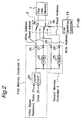
- Fig. 2 is a schematic block diagram of a
first memory controller 3, asecond memory controller 4 and afirst switch 5 which are shown in Fig. 1; - Fig. 3 is a front view of an image on a television display showing a method of dividing the image into a plurality of compression blocks;
- Fig. 4 is a schematic block diagram showing digital video data written into and read out from a
first line memory 2 in both cases of selecting the first andsecond memory controllers - Fig. 5 is a schematic diagram showing compositions of a plurality of SYNC blocks which are used in the preferred embodiments;
- Fig. 6 is a schematic diagram showing compressed digital video data which is used in the preferred embodiments; and
- Fig. 7 is a schematic diagram of a
video tape recorder 74 and acompression adapter 201, according to a second preferred embodiment of the present invention. - The preferred embodiments according to the present invention will be described below with reference to the attached drawings.
- Fig. 1 is a schematic block diagram of an apparatus for recording and reproducing compressed or non-compressed digital video data (referred to as a recording and reproducing apparatus hereinafter), according to a first preferred embodiment of the present invention. In the first preferred embodiment, compressed or non-compressed digital video data is inputted through an
input terminal 1, and then the digital video data is recorded and reproduced. - In the present preferred embodiment, when recording and reproducing non-compressed video data, the luminance signal of one horizontal scanning line is sampled at 18 MHz, whereas the two color difference signals of one horizontal scanning line are sampled at 9 MHz, respectively. Further, 960 samples of the luminance signal of one horizontal scanning line is quantized into eight-bit video data, whereas 480 samples of the color difference signal of one horizontal scanning line is quantized into eight-bit video data. Furthermore, the number of recording horizontal scanning lines is 255 lines/field. Therefore, when the digital video data compressed by the recording and reproducing apparatus of the present preferred embodiment is recorded and reproduced, the upper limit of the compressed digital video data is (255 x 2 x 960) Bytes.
- The composition of the recording and reproducing apparatus of the first preferred embodiment will be described below in detail with reference to Fig. 1.
- The recording and reproducing apparatus of the first preferred embodiment comprises:
- (a) the
input terminal 1 for inputting compressed or non-compressed digital video data; - (b) a
first line memory 2 for temporarily storing digital video data inputted through theinput terminal 1, wherein thefirst line memory 2 is of a line memory for storing digital video data of one horizontal scanning line; - (c) a
first memory controller 3 for performing a shuffling process every horizontal scanning line for the digital video data stored in thefirst line memory 2; and - (d) a
second memory controller 4 for performing delay process for the digital video data stored in thefirst line memory 2 by a predetermined time interval, without the shuffling process. - The write address and the read address outputted from the
first memory controller 3 are inputted through afirst switch 5 to thefirst line memory 2, whereas the write address and the read address outputted from thesecond memory controller 4 are inputted through thefirst switch 5 to thefirst line memory 2. When a signal representing that non-compressed digital video data is inputted through theinput terminal 1 is inputted from an outer unit through anouter input terminal 30 to afirst switching controller 19, thefirst switching controller 19 controls thefirst switch 5 to be switched over so that thefirst memory controller 3 is connected through thefirst switch 5 to thefirst line memory 2, and further outputs a compression flag "0" to a compressionflag adding circuit 31. On the other hand, when a signal representing that compressed digital video data is inputted through theinput terminal 1 is inputted from the outer unit through theouter input terminal 30 to thefirst switching controller 19, thefirst switching controller 19 controls thefirst switch 5 to be switched over so that thesecond memory controller 4 is connected through thefirst switch 5 to thefirst line memory 2, and further outputs a compression flag "1" to the compressionflag adding circuit 31. - The recording and reproducing apparatus of the first preferred embodiment further comprises:
- (a) the compression
flag adding circuit 31 for adding the compression flag "1" or "0" into the digital video data read out from thefirst line memory 2; - (b) an error
parity adding circuit 6 for calculating an error parity every predetermined SYNC block and adding the calculated error parity to the digital video data outputted from the compressionflag adding circuit 31; - (c) a
recording processing circuit 7 for modulating a carrier signal according to the digital video data using a predetermined modulation method and amplifying the modulated signal; and - (d) a recording
magnetic head 8 for recording the modulated signal outputted from therecording processing circuit 7, onto a magnetic tape. - Further, the recording and reproducing apparatus of the first preferred embodiment further comprises:
- (a) a reproducing magnetic head 9 for reproducing the modulated signal recorded on the magnetic tape;
- (b) a reproducing
processing circuit 10 for amplifying the modulated signal reproduced by the reproducing magnetic head 9 and demodulating the amplified signal so as to obtain reproduced digital video data; - (c) an error correction circuit 11 for performing an error correction process for the digital video data outputted from the reproducing
processing circuit 10; - (d) a compression
flag detecting circuit 32 for detecting the compression flag "1" or "0" included in the digital video data outputted from the error correction circuit 11, outputting the compression flag to thesecond switching controller 20, removing the compression flag from the inputted digital video data, and then outputting the digital video data to asecond line memory 12; - (e) the
second line memory 12 for temporarily storing the digital video data outputted from the compressionflag detecting circuit 32, wherein thesecond line memory 12 is of a lime memory for storing digital video data of one horizontal scanning line; - (f) a
third memory controller 13 for performing a deshuffling process which is opposite to the shuffling process of thefirst memory controller 3, every horizontal scanning line, for the digital video data stored in thesecond line memory 12; and - (g) a
fourth memory controller 14 for performing a delay process for the digital video data stored in thesecond line memory 12 by a predetermined time interval, without the deshuffling process. - In response to the compression flag "0" representing that the reproduced digital video data is the non-compressed video data, the
second switching controller 20 controls asecond switch 15 to be switched over so that thethird memory controller 13 is connected through thesecond switch 15 to thesecond line memory 12. On the other hand, in response to the compression flag "1" representing that the reproduced digital video data is the compressed video data, thesecond switching controller 20 controls thesecond switch 15 to be switched over so that thefourth memory controller 13 is connected through thesecond switch 15 to thesecond line memory 12. - Furthermore, the recording and reproducing apparatus of the first preferred embodiment further comprises:
- (a) an
error concealment circuit 16 for performing an error concealment process for the digital video data read out from thesecond line memory 12, by predictively interpolating the inputted digital video data which could not be corrected by the error correction circuit 11; and - (b) a
data converting circuit 18 for converting eight-bit digital video data into ten-bit data including two bits composed of an error flag and an inverted signal of the error flag signal, and outputting the converted data including the eight-bit digital video data, the error flag, and the inverted signal of the error flag, through anoutput terminal 17 to an outer unit. - The operation of the recording and reproducing apparatus of the first preferred embodiment will be described below in detail with reference to Fig. 1.
- First of all, the case where non-compressed digital video data is recorded and reproduced will be described below. When non-compressed digital video data is inputted through the
input terminal 1 to thefirst line memory 2, the signal representing that the non-compressed digital video data is inputted through theinput terminal 1 is inputted through theinput terminal 30 to thefirst switching controller 19, and then thefirst switching controller 19 controls thefirst switch 5 to be switched over so that thefirst memory controller 3 is connected through thefirst switch 5 to thefirst line memory 2. On the other hand, the non-compressed digital video data is written into thefirst line memory 2 every horizontal scanning line by the write control of thefirst memory controller 3. Thereafter, the digital video data written in thefirst line memory 2 is read out therefrom by read control of thefirst memory controller 3 in an order different from that when writing the digital video data in thefirst line memory 2, wherein the process for changing the order is called a shuffling process. - In the present preferred embodiment, the digital video data is shuffled within one horizontal scanning line with one block of one horizontal scanning line. In this case, the order of the digital video data is preferably changed so that the adjacent samples are located far away from each other as far as possible on a track of the magnetic tape.
- The digital video data shuffled by the
first memory controller 3 being read out from thefirst line memory 2 is inputted to the compressionflag adding circuit 31, which then adds the compression flag "0" to the inputted digital video data and thereafter outputs the digital video data with the compression flag "0" to the errorparity adding circuit 6. Thereafter, the errorparity adding circuit 6 calculates a parity code such as the Read Solomon code which is known to those skilled in the art, or the like, based on the inputted digital video data, adds the parity code to the inputted digital video data, and then outputs the digital video data with the parity code through therecording processing circuit 7 including the modulation and amplification functions to the recordingmagnetic head 8, thereby recording the digital video signal onto a magnetic tape (not shown). Adding the parity code thereto can remove almost all the data errors which may be caused in the recording and reproducing processes, in the error correction circuit 11 of the reproducing side. - On the other hand, the digital video signal reproduced by the reproducing magnetic head 9 is inputted as the digital video data to the error correction circuit 11 through the reproducing
processing circuit 10 including the amplification and demodulation functions. Thereafter, the error correction circuit 11 performs the error correction process for the reproduced digital video data based on the parity code included in the reproduced digital video data, and outputs to the compressionflag detecting circuit 32, not only the corrected digital video data but also an error flag representing the position of the digital video data which could not be corrected by the error correction circuit 11. Then the compressionflag detecting circuit 32 detects the compression flag "0" included in the digital video data, outputs the detected compression flag "0" to thesecond switching controller 20, removes the compression flag "0" from the inputted digital video data, and then outputs the digital video data together with the error flag after removing the compression flag "0", to thesecond line memory 12. - In response to the compression flag "0", the
second switching controller 20 controls thesecond switch 15 to be switched over so that thethird memory controller 13 is connected through thesecond switch 15 to thesecond line memory 12. In this case, the digital video data with the error flag is written in thesecond line memory 12 and is read out therefrom by thethird memory controller 13 performing the deshuffling process which is opposite to the shuffling process of thefirst memory controller 3, so that the order of the digital video data written in thesecond line memory 12 is returned to the same order as that of the digital video data written in thefirst line memory 2. - The digital video data together with the error flag is read out from the
second line memory 12 is inputted to theerror concealment circuit 16, which then predictively interpolates the pixel data judged as the error data based on the above-mentioned error flag, from the adjacent pixel data located in the periphery of the judged pixel data, and outputs the interpolated digital video data to thedata converting circuit 16. In this case, thedata converting circuit 18 inserts a synchronizing signal or code etc. into the inputted digital video data according to a data format represented in the CCIR No. 601 Recommendation without performing another particular process, and then outputs the digital video data together with the synchronizing signal or code through theoutput terminal 17. - As described above, in the case of recording the non-compressed digital video data onto the magnetic tape, the digital video data is recorded after the shuffling process. Therefore, the burst errors on the magnetic tape are dispersed in an image displayed on the television display, and there becomes a higher possibility that a pixel data adjacent to an error pixel data does not become error. As a result, the performance of the error concealment process for predictively interpolating the error pixel data based on the pixel data located in the periphery of the error pixel data can be heightened.
- Next, the case where compressed digital video data is recorded and reproduced will be described below. In the present preferred embodiment, when the compressed digital video data is recorded, a predetermined compression adapter (not shown) is connected to the
input terminal 1, and the compressed digital video data is inputted to theinput terminal 1. - Fig. 3 is a front view of an image on a television display showing a method of dividing the image into a plurality of compression blocks. As shown in Fig. 3, the video data of one field is divided into a plurality of blocks A(1, 1), A(1, 2), A(1, 3), ... in an order thereof. In the compression adapter of the present preferred embodiment, as shown in Fig. 3, for example, the video data of one field is compressed so that the digital video data of 8 pixels x 8 horizontal scanning lines is packaged as one compression block. Within the compression block, for example, the discrete cosine transform (referred to as a DCT hereinafter) etc. is performed for the digital video data, and thereafter, the digital video data after the DCT is converted into a Huffman code etc. The Huffman-coded digital video data is outputted from the compression adapter (not shown) through the
input terminal 1 to the recording and reproducing apparatus of the first preferred embodiment. In this case, the second andfourth memory controllers second memory controller 4 is connected through thefirst switch 5 to thefirst line memory 2 and thefourth memory controller 14 is connected through thesecond switch 15 to thesecond line memory 12. Then, the compressed digital video data is written into thefirst line memory 2, and then is read out from thefirst line memory 2 performing only the delay process without the shuffling process by thesecond memory controller 4. - Next, the composition and operation of the first and
second memory controllers first memory controller 3, thesecond memory controller 4 and thefirst switch 5 which are shown in Fig. 1. - Referring to Fig. 2, 21 denotes a video signal reference pulse such as a horizontal synchronizing signal or the like which becomes a reset signal for a counter circuit 23 as described later; 22 denotes a clock such as a pixel clock; 23 denotes a counter circuit for counting the clock and outputting an address representing the counts of the clocks; 24 denotes a first read only memory (a read only memory is referred to as a ROM hereinafter) for converting the output address from the counter circuit 23 into a
first read address 27; 25 denotes a second ROM for converting the output address from the counter circuit 23 into a second read address 29; 26 denotes a first write address which is the same as the output address from the counter circuit 23; and 28 denotes a second write address which is the same as the output address from the counter circuit 23. - The
first switch 5 comprisesswitches first switching controller 19 as described above. - The operation of the first and
second memory controllers - The video signal reference pulse 21 such as the horizontal synchronizing signal or the like and the
clock 22 are inputted to the counter circuit 23, which is reset in response to the video signal reference pulse 21, and thereafter counts the number of theclocks 22. In other words, the number of counts of the counter circuit 23 or the output address is incremented by one every leading edge of theclock 22. The output address of the counter circuit 23 becomes not only thefirst write address 26 which is an output of thefirst memory controller 3, but also the second write address 28 which is an output of thesecond memory controller 4. Further, the output address of the counter circuit 23 is inputted to the address terminal of thefirst ROM 24, which converts the inputted address into the first read address which is another output of thefirst memory controller 3. Furthermore, the output address of the counter circuit 23 is inputted to the address terminal of the second ROM 25, which converts the inputted address into the second read address which is another output of thesecond memory controller 4. - When the non-compressed digital video data is inputted through the
input terminal 1, thewrite address 26 and the readaddress 27 which are outputted from thefirst memory controller 3 are inputted through theswitches first line memory 2. On the other hand, when the compressed digital video data is inputted through theinput terminal 1, the write address 28 and the read address 29 which are outputted from thesecond memory controller 4 are inputted through theswitches first line memory 2. - Fig. 4 is a schematic block diagram showing video data written into and read out from a
first line memory 2 in both the cases of selecting the first andsecond memory controllers first line memory 2. - The middle view of Fig. 4 shows the order of the digital video data read out from the
first line memory 2 in the case of selecting thefirst memory controller 3. This shows the shuffling process. - On the other hand, the lower view of Fig. 4 shows the order of the digital video data read out from the
first line memory 2 in the case of selecting thesecond memory controller 4. This shows only delay process without performing the shuffling process. - In the present preferred embodiment, even when one data selected among the non-compressed digital video data and the compressed digital video data is recorded onto the magnetic tape, the inputted digital video data is written into the
first line memory 2 in the order when they are inputted to theinput terminal 1 since the output address of the counter circuit 23 becomes thewrite address 26 or 28 as it is. On the other hand, upon reading out the digital video data from thefirst line memory 2, since the read address is converted into the write address by theROM 24 or 25, by changing only the contents of theROM 24 and 25, it is determined whether or not the shuffling process is to be performed. - When the non-compressed digital video data is inputted to the
input terminal 1, thefirst memory controller 3 is selected, and then the digital video data is read out from thefirst line memory 2 performing the shuffling process as shown in the middle view of Fig. 4. On the other hand, when the compressed digital video data is inputted to theinput terminal 1, thesecond memory controller 4 is selected. and then the digital video data is read out from thefirst line memory 2 in the same order as that when writing the same in thefirst line memory 2 as shown in the lower view of Fig. 4. - In the present preferred embodiment, the read address for the
first line memory 2 is converted by theROMs 24 and 25, however, the present invention is not limited to this. The converting ROMs may be provided in the write address lines. - In the present preferred embodiment, the ROMs are used as means for converting the address, however, the present invention is not limited to this. The address may be converted by calculating the address using a calculation circuit.
- Referring back to Fig. 1 in the case of selecting the
second memory controller 4, the compressed digital video data read out from thefirst line memory 2 by control of thesecond memory controller 4 is inputted to the compressionflag adding circuit 31, and then the compression flag "1" is added to the read-out digital video data by the compressionflag adding circuit 31. Thereafter, the compressed digital video data together with the compression flag "1" is inputted to the errorparity adding circuit 6, which forms a block to be recorded onto a magnetic tape as shown in Fig. 5. Hereinafter, the unit block when recording the digital video data onto the magnetic tape is referred to as a SYNC block. As is apparent from Fig. 5, one SYNC block is composed of the followings: - (a) a synchronizing signal (SYNC) representing a start of the block on the magnetic tape;
- (b) an index signal (ID) representing a position of the block;
- (c) three-block digital video data; and
- (d) an error correction parity for the error correction process to be performed by the error correction circuit 11.
- In Fig. 5, the digital video data A(1, 1), A(1, 2), A(1, 3), ... correspond to the block numbers of the compression blocks shown in Fig. 3. In this case, the
second memory controller 4 is selected and then the shuffling process is not performed. Therefore, the digital video data of one compression block are arranged so as not to be included over a plurality of SYNC blocks. In other words, the number of the compression blocks included in one SYNC block can be suppressed to the necessary lower limit. Therefore, for example, upon the search operation, when all the digital video data recorded on the magnetic tape is not reproduced, the reproduced digital video data which has been compressed in the unit of the SYNC block can be recovered or restored. Further, even when one SYNC block is removed or broken due to damage of the magnetic tape or the like, this relatively reduces the influence to many compression blocks. - The signal processing when reproducing the compressed digital video data will be described below in details.
- The modulated digital video signal reproduced by the reproducing magnetic head 9 is inputted to the reproducing producing
circuit 10, which amplifies and demodulates the reproduced modulated digital video signal, thereby obtaining and outputting the digital video data to the error correction circuit 11. Then the error correction circuit 11 performs the error correction process for the reproduced digital video data in a manner similar to that as described above, and outputs the digital video data together with the error flag representing the position of the digital video data which could not be corrected by the error correction circuit 11, through the compressionflag detecting circuit 32 to thesecond line memory 12. - The compression
flag detecting circuit 32 detects the compression flag "1" included in the digital video data, and then outputs the compression flag "1" to thesecond switching controller 20. In response to the compression flag "1", thesecond switching controller 20 controls thesecond switch 15 to be switched over so that thefourth memory controller 14 is connected through thesecond switch 15 to thesecond line memory 12. That is, the write and read operation of thesecond line memory 12 is controlled by thefourth memory controller 14. The control operation of thefourth memory controller 14 is opposite to that of thesecond memory controller 4, and in this case, since the digital video data has not been shuffled in the recording side, the digital video data stored in thesecond line memory 12 is read out in the same order as the order when writing the digital video data. The digital video data read out from thesecond line memory 12 is inputted to theerror concealment circuit 16. When the compressed digital video data is reproduced, the error concealment process is not performed in this case. That is, the operation of theerror concealment circuit 16 is disabled in this case. The digital video data together with the error flag added by the error correction circuit 11 is inputted to thedata converting circuit 18, which converts the inputted data into the digital video data in a manner as described later in details. Thereafter, the converted digital video data is outputted through theoutput terminal 17. - When the compressed digital video data is recorded in the manner as described above, the shuffling and deshuffling processes are not performed. Therefore, the fundamental data of one compression block is included in one SYNC block. Even when one SYNC block is damaged or broken due to damage of the magnetic tape or the like, the influence can not be propagated to many compression blocks.
- In the present preferred embodiment, one SYNC block includes three compression blocks, such as A(1 ,1), A(1, 2) and A(1, 3), which are to be packaged as a set of compression blocks, however, the present invention is not limited to this. One SYNC block may includes one or more compression blocks which are to be packaged as a set of compression blocks. Only relatively important data of the compression block may be packaged as only single SYNC block.
- In the present preferred embodiment, the operation of the error
parity adding circuit 6 is not described in details. The error parity may be in a product form including an inner party and an outer parity, in order to heighten the performance of the error correction. - The operation of the
data converting circuit 18 will be described below in details. - In the
data converting circuit 18, the error flag representing the digital video data which could not be corrected by the error correction circuit 11 and the inverted signal of the error flag are assigned as the most significant two bits, whereas the digital video data is assigned as the lower eight bits, thereby extending the reProduced digital video data into ten bits. This extended reproduced digital video data is outputted through theoutput terminal 17. - Fig. 6 is a schematic diagram showing the compressed digital video data which is outputted from the
data converting circuit 18. - Referring to Fig. 6, the inverted flag of the error flag is assigned to the most significant bit (MSB) or 10-th bit, the error flag is assigned to the 9-th bit, and the compressed digital video data is assigned to the lower eight bits from 8-th to first bits. Further, the synchronizing signal is assigned as ten bits of the start and end of the effective sample of one horizontal scanning line. The synchronizing signal is constituted by "3FF" and "000" in the sexadecimal notation in a data format which is represented in the CCIR No. 601 Recommendation. Therefore, in the interface of ten bits thereof, "3FF" and "000" in the sexadecimal notation of the digital video data are set as inhibit code. Therefore, in the present preferred embodiment, the error flag and the inverted signal of the error flag are assigned to the MSB and the 9-th bit, and "3FF" and "000" in the sexadecimal notation are inhibited or prohibited in the region of the digital video data.
- Accordingly, the error flag representing detecting the error position caused upon the reproducing process can be transmitted to an outer unit such as a compression adapter or the like, using an interface in conformity to the data format represented in the CCIR No. 601 Recommendation, and then an error concealment process can be performed by the above-mentioned compression adapter for recovering or restoring the compressed digital video data after recovering or restoring the same. This results in obtaining a better quality of reproduced image on a television display.
- Fig. 7 is a schematic diagram of a
VTR 74 and acompression adapter 201, according to a second preferred embodiment of the present invention. - Referring to Fig. 7, the
compression adapter 201 comprises: - (a) an
input terminal 70 for inputting a video signal; - (b) a
compression encoder 71 for compressing the video signal inputted through theinput terminal 70 so as to obtain compressed video data of eight bits; - (c) a
data converting circuit 72 for converting the compressed video data of eight bits outputted from thecompression encoder 71 into transmission data of ten bits having a data format including the compressed digital video data of eight bits, which can be transmitted to theVTR 74; - (d) an
output terminal 73 for outputting the compressed video data of ten bits to theVTR 74; - (e) an
input terminal 75 for inputting reproduced compressed video data outputted from thecompression adapter 201; - (f) a
data detecting circuit 76 for decoding the compressed video data having the data format shown in Fig. 6 so as to convert the same into compressed video data having a predetermined data format, wherein thedata detecting circuit 76 detects the synchronizing signal, the error flag, and the compressed digital video data included in the data format shown in Fig. 6 so as to separate these data, and then separately outputs the detected digital video data together with the synchronizing signal and the error flag; - (g) a
compression decoder 77 for performing a decompression process and an inverse process of the DCT process for the digital video data of the compression blocks having no error which are indicated by the error flag so as to convert the same into the original digital video data, and outputting the decompressed digital video data together with the error flag; - (h) an error concealment circuit 78 for performing an error concealment process so as to predictively interpolating the digital video data using the digital video data of the SYNC block one frame before or one field before, in a manner similar to that of the
error concealment circuit 16 of the first preferred embodiment, and outputting the original digital video data having no error; and - (i) an
output terminal 79 for outputting the decompressed original digital video data. - In the
compression adapter 201, thecompression decoder 77 and the error concealment circuit 78 is included in adata recovery circuit 80. - The
VTR 74 comprises: - (a) a
data detecting circuit 101 for detecting and extracting the compressed digital video data of eight bits from the inputted transmission data of ten bits, and outputting the extracted compressed digital video data of eight bits; - (b) an error
parity adding circuit 102 for operating in the same manner as that of the errorparity adding circuit 6 of the first preferred embodiment; - (c) a
recording processing circuit 103 for operating in the same manner as that of therecording processing circuit 7 of the first preferred embodiment; - (d) a recording
magnetic head 104 for operating in the same manner as that of the recordingmagnetic head 8 of the first preferred embodiment; - (e) a reproducing
magnetic head 105 for operating in the same manner as that of the reproducing magnetic head 9 of the first preferred embodiment; - (f) a reproducing
processing circuit 106 for operating in the same manner as that of the reproducingprocessing circuit 10 of the first preferred embodiment; - (g) an
error correction circuit 107 for operating in the same manner as that of the error correction circuit 11 of the first preferred embodiment, and outputting the reproduced compressed digital video data together with error flags; - (h) a
data converting circuit 108 for converting the reproduced compressed digital video data and the error flags into digital transmission data having a data format in conformity to the data format represented in the CCIR No. 601 Recommendation. - The operation of the apparatuses shown in Fig. 7 when compressed digital video data is recorded and reproduced will be described below in details.
- First of all, the operation of the recording side will be described hereinafter. A video signal is inputted through the
input terminal 70 to thecompression encoder 71, and then thecompression encoder 71 performs the DCT process and the high-efficiency encoding process such as the entropy encoding process or the like for the inputted video signal so as to convert the same into compressed digital video data of eight bits, and outputs the compressed digital video data of eight bits to thedata converting circuit 72. Then thedata converting circuit 72 adds the synchronizing signal, the error flag and the inverted signal of the error flag to the inputted compressed digital video data so as to convert the inputted data into the transmission data of ten bits. In the transmission data of ten bits outputted from thedata converting circuit 72, since there is no error due to reproduction of the magnetic tape, all the error flags are set to one as dummy bits, and all the inverted flag thereof are set to zero as dummy bits. In other words, the transmission data of ten bits outputted from thedata converting circuit 72 through theoutput terminal 73 includes the following data format: - (a) the most significant bit which is set to zero as a dummy bit;
- (b) the second bit which is set to one as a dummy bit; and
- (c) the lower eight bits composed of the compressed digital video data.
- The transmission data having the above-mentioned data format is inputted to the data detecting 101 of the
VTR 74. Then, thedata detecting circuit 101 detects and separates only the compressed digital video data of eight bits inserted in the lower eight bits from the inputted data, and outputs the separated compressed digital video data to theerror parity circuit 102. The errorparity adding circuit 102 adds the correction parity to the inputted data in a manner similar to that of the errorparity adding circuit 102, and outputs the digital video data of eight bits together with the error parity through therecording processing circuit 103 to the recordingmagnetic head 104, thereby recording the digital video signal having these data onto a magnetic tape (not shown). - Next, the operation of the reproducing side will be described below. The digital video signal is reproduced from the magnetic tape, and then the reproducing
processing circuit 106 performs the amplification process and the demodulation process for the inputted reproduced digital video signal so as to convert the inputted reproduced digital video signal into the digital video data, which is outputted to theerror correction circuit 107. Theerror correction circuit 107 performs the error correction process for the inputted digital video data based on the parity code included in the digital video data in order to correct the errors which may be caused in the recording and reproducing processes, and outputs to thedata converting circuit 108, not only the corrected digital video data but also an error flag representing the position of the digital video data which could not be corrected by theerror correction circuit 107. Thedata converting circuit 108 converts the inputted data into transmission data having the following data format shown in Fig. 6 and in conformity to the data format represented in the CCIR No. 601 Recommendation, and then outputs the converted transmission data together with the synchronizing signal: - (a) the most significant bit in which the inverted signal of the error is inserted;
- (b) the second bit in which the error flag is inserted; and
- (c) the lower eight bits in which the compressed digital video data.
- Thereafter, the data outputted from the
data converting circuit 108 of theVTR 108 is inputted through theinput terminal 75 to thedata detecting circuit 76, and then thedata converting circuit 76 detects and separates the synchronizing signal, the error flag, the inverted signal of the error flag, and the compressed video data, and separately outputs these data to thecompression decoder 77 of thedata recovery circuit 80. Thereafter, thecompression decoder 77 performs the decompression process and the inverted process of the DCT process for the inputted digital video data of the compression blocks having no error so as to convert the same into the original digital video data, and outputs the decompressed digital video data and the digital video data of compression blocks having errors to the error concealment circuit 78. The error concealment circuit 78 performs the error concealment process for the digital video data of compression blocks having errors corresponding to error flags so as to predictively interpolating the error digital video data using the decompressed data one frame before or one field before, thereby obtaining the interpolated no-error digital video data. This results in obtaining the original digital video data, which is outputted through theoutput terminal 79. - In the present preferred embodiment, the error concealment process is performed for the output data from the
compression decoder 77, however, the present invention is not limited to this. The error concealment process may be performed for the compressed digital video data which is the output data from thedata detecting circuit 76. - In the recording side of the apparatuses shown in Fig. 7, in the
data converting circuit 72, the inputted data is converted into the transmission data having the following data format: - (a) the most significant bit to which data "one" is assigned;
- (b) the second bit to which data "zero" is assigned; and
- (c) the lower eight bits to which the compressed digital video data is assigned. This can set "000" to "003" in the sexadecimal notation and "3FD" to "3FF" in the sexadecimal notation which are prohibited in the 10-bit digital interface, to inhibit codes. The above-mentioned transmission data of ten bits having the above-mentioned data format can be transmitted in conformity to the data format represented in the CCIR No. 601 Recommendation.
- In the present preferred embodiment, the above-mentioned data format includes the eight-bit digital video data, however, the present invention is not limited to this. The above-mentioned data format may include natural number-N-bit digital video data.
- In the reproducing side of the apparatuses shown in Fig. 7, in the
data converting circuit 108, the error flag and the inverted signal of the error flag, which represents an error caused in the recording and reproducing processes of the compressed digital video data, are assigned to the higher ten bits, whereas the compressed digital video data is assigned to the lower eight bits, thereby extending the data format of eight bits to the data format of ten bits. This can set "000" to "003" in the sexadecimal notation and "3FD" to "3FF" in the sexadecimal notation which are prohibited in the 10-bit digital interface, to inhibit codes. The data of ten bits having the above-mentioned data format can be transmitted in conformity to the data format represented in the CCIR No. 601 Recommendation. - In the present preferred embodiment, the
compression adapter 201 comprising thecompression encoder 71, thedata converting circuit 72, thedata detecting circuit 76 and thedata recovery circuit 80 can be constituted so as to be separated from theVTR 74. Upon recording and reproducing the digital video signal of the current television system, theVTR 74 is used without thecompression adapter 201. On the other hand, upon recording and reproducing the digital video signal of the future television system such as an HDTV system or the like, theVTR 74 is used with thecompression adapter 201. Thus, even though digital video signal of the future television system is recorded and reproduced, the conventional VTR can be effectively utilized, advantageously. - As described above, an interface between the
VTR 74 and thecompression adapter 201 is only one serial transmission line, and then another transmission line for transmitting the error flag is not necessary, advantageously. - Although the present invention has been fully described in connection with the preferred embodiments thereof with reference to the accompanying drawings, it is to be noted that various changes and modifications are apparent to those skilled in the art. Such changes and modifications are to be understood as included within the scope of the present invention as defined by the appended claims unless they depart therefrom.
Claims (4)
- An apparatus for recording digital video data, comprising:
compression means for compressing digital video data inputted to said apparatus, and outputting a compressed digital video data;
first data converting means for converting the compressed digital video data outputted from said compression means into transmission data having a predetermined data format by adding a dummy bit of one and another dummy bit of zero to each of the digital video data of natural number N bits;
first data detecting means for removing the dummy bits of two bits from the transmission data outputted from said first data converting means so as to obtain the digital video data of N bits, and outputting the digital video data of N bits;
error parity adding means for adding an error parity to the digital video data of N bits outputted from said first data detecting means and outputting the digital video data of N bits together with the error parity; and
recording means for recording the digital video data of N bits and the error parity onto a recording medium. - An apparatus for reproducing compressed digital video data, comprising:
reproducing means for reproducing compressed digital video data of natural number N bits including error parity from a recording medium;
error correction means for correcting errors in the compressed digital video data of N bits reproduced by said reproducing means based on the error parity reproduced by said reproducing means, generating an error flag when the compressed digital video data of N bits can not corrected upon said correcting errors, and outputting the compressed digital video data of N bits together with the error flag representing the compressed digital video data of N bits which can not corrected;
second data converting means for converting the compressed digital video data of N bits outputted from said error correction means into transmission data having a predetermined data format by adding the error flag and the inverted signal of the error flag to each of the compressed digital video data of natural number N bits;
second data detecting means, responsive to the compressed digital video data and the error flag outputted from said second data converting means, for separating the error flag from the compressed digital video data of N bits, and separately outputting the compressed digital video data of N bits and the error flag; and
data recovery means, responsive to the compressed digital video data of N bits and the error flag outputted from said second data detecting means, for decompressing the compressed digital video data of N bits outputted from said second data detecting means so as to obtain decompressed digital video data, and concealing the error in the decompressed digital video data represented by the error flag based on the error flag. - An apparatus for recording and reproducing digital video data, comprising:
compression means for compressing digital video data inputted to said apparatus, and outputting a compressed digital video data;
first data converting means for converting the compressed digital video data outputted from said compression means into transmission data having a predetermined data format by adding a dummy bit of one and another dummy bit of zero to each of the digital video data of natural number N bits;
first data detecting means for removing the dummy bits of two bits from the transmission data outputted from said first data converting means so as to obtain the digital video data of N bits, and outputting the digital video data of N bits;
error parity adding means for adding an error parity to the digital video data of N bits outputted from said first data detecting means and outputting the digital video data of N bits together with the error parity;
recording means for recording the digital video data of N bits and the error parity onto a recording medium;
reproducing means for reproducing the compressed digital video data of natural number N bits including error parity from said recording medium;
error correction means for correcting errors in the compressed digital video data of N bits reproduced by said reproducing means based on the error parity reproduced by said reproducing means, generating an error flag when the compressed digital video data of N bits can not corrected upon said correcting errors, and outputting the compressed digital video data of N bits together with the error flag representing the compressed digital video data of N bits which can not corrected;
second data converting means for converting the compressed digital video data of N bits outputted from said error correction means into transmission data having a predetermined data format by adding the error flag and the inverted signal of the error flag to each of the compressed digital video data of natural number N bits;
second data detecting means, responsive to the compressed digital video data and the error flag outputted from said second data converting means, for separating the error flag from the compressed digital video data of N bits, and separately outputting the compressed digital video data of N bits and the error flag; and
data recovery means, responsive to the compressed digital video data of N bits and the error flag outputted from said second data detecting means, for decompressing the compressed digital video data of N bits outputted from said second data detecting means so as to obtain decompressed digital video data, and concealing the error in the decompressed digital video data represented by the error flag based on the error flag. - A compression adapter for connecting to an apparatus for recording and reproducing digital video data, comprising:
compression means for compressing digital video data inputted to said compression adapter, and outputting a compressed digital video data;
first data converting means for converting the compressed digital video data outputted from said compression means into transmission data having a predetermined data format by adding a dummy bit of one and another dummy bit of zero to each of the digital video data of natural number N bits, and outputting the transmission data to said apparatus;
second data detecting means, responsive to digital video data of N bits and an error flag outputted from said apparatus, for separating the error flag from the compressed digital video data of N bits, and separately outputting the compressed digital video data of N bits and the error flag; and
data recovery means, responsive to the compressed digital video data of N bits and the error flag outputted from said second data detecting means, for decompressing the compressed digital video data of N bits outputted from said second data detecting means so as to obtain decompressed digital video data, and concealing the error in the decompressed digital video data represented by the error flag based on the error flag.
Applications Claiming Priority (4)
| Application Number | Priority Date | Filing Date | Title |
|---|---|---|---|
| JP05150083A JP3141629B2 (en) | 1993-06-22 | 1993-06-22 | Video signal recording and playback device |
| JP15008393 | 1993-06-22 | ||
| JP150083/93 | 1993-06-22 | ||
| EP94109531A EP0631436B1 (en) | 1993-06-22 | 1994-06-21 | Apparatus for recording and reproducing compressed or non-compressed digital video data |
Related Parent Applications (2)
| Application Number | Title | Priority Date | Filing Date |
|---|---|---|---|
| EP94109531A Division EP0631436B1 (en) | 1993-06-22 | 1994-06-21 | Apparatus for recording and reproducing compressed or non-compressed digital video data |
| EP94109531.7 Division | 1994-06-21 |
Publications (3)
| Publication Number | Publication Date |
|---|---|
| EP0666692A2 true EP0666692A2 (en) | 1995-08-09 |
| EP0666692A3 EP0666692A3 (en) | 1995-10-04 |
| EP0666692B1 EP0666692B1 (en) | 1999-11-10 |
Family
ID=15489146
Family Applications (2)
| Application Number | Title | Priority Date | Filing Date |
|---|---|---|---|
| EP94109531A Expired - Lifetime EP0631436B1 (en) | 1993-06-22 | 1994-06-21 | Apparatus for recording and reproducing compressed or non-compressed digital video data |
| EP95106159A Expired - Lifetime EP0666692B1 (en) | 1993-06-22 | 1994-06-21 | Apparatus for recording and reproducing compressed or non-compressed digital video data with compression adapter |
Family Applications Before (1)
| Application Number | Title | Priority Date | Filing Date |
|---|---|---|---|
| EP94109531A Expired - Lifetime EP0631436B1 (en) | 1993-06-22 | 1994-06-21 | Apparatus for recording and reproducing compressed or non-compressed digital video data |
Country Status (3)
| Country | Link |
|---|---|
| EP (2) | EP0631436B1 (en) |
| JP (1) | JP3141629B2 (en) |
| DE (2) | DE69421605T2 (en) |
Families Citing this family (10)
| Publication number | Priority date | Publication date | Assignee | Title |
|---|---|---|---|---|
| US5862035A (en) | 1994-10-07 | 1999-01-19 | Maxwell Energy Products, Inc. | Multi-electrode double layer capacitor having single electrolyte seal and aluminum-impregnated carbon cloth electrodes |
| US6233135B1 (en) | 1994-10-07 | 2001-05-15 | Maxwell Energy Products, Inc. | Multi-electrode double layer capacitor having single electrolyte seal and aluminum-impregnated carbon cloth electrodes |
| US6449139B1 (en) | 1999-08-18 | 2002-09-10 | Maxwell Electronic Components Group, Inc. | Multi-electrode double layer capacitor having hermetic electrolyte seal |
| US6631074B2 (en) | 2000-05-12 | 2003-10-07 | Maxwell Technologies, Inc. | Electrochemical double layer capacitor having carbon powder electrodes |
| US6813139B2 (en) | 2001-11-02 | 2004-11-02 | Maxwell Technologies, Inc. | Electrochemical double layer capacitor having carbon powder electrodes |
| US6643119B2 (en) | 2001-11-02 | 2003-11-04 | Maxwell Technologies, Inc. | Electrochemical double layer capacitor having carbon powder electrodes |
| US7791860B2 (en) | 2003-07-09 | 2010-09-07 | Maxwell Technologies, Inc. | Particle based electrodes and methods of making same |
| US7920371B2 (en) | 2003-09-12 | 2011-04-05 | Maxwell Technologies, Inc. | Electrical energy storage devices with separator between electrodes and methods for fabricating the devices |
| US7090946B2 (en) | 2004-02-19 | 2006-08-15 | Maxwell Technologies, Inc. | Composite electrode and method for fabricating same |
| US7440258B2 (en) | 2005-03-14 | 2008-10-21 | Maxwell Technologies, Inc. | Thermal interconnects for coupling energy storage devices |
Citations (3)
| Publication number | Priority date | Publication date | Assignee | Title |
|---|---|---|---|---|
| DE2947874A1 (en) * | 1979-11-28 | 1981-06-04 | Institut für Rundfunktechnik GmbH, 8000 München | Digital coder for video information on tape - has analogue signals converted to digital form and transcoded multiplexed and modulated before recording |
| EP0338781A2 (en) * | 1988-04-19 | 1989-10-25 | Sony Corporation | Data transmission and recording |
| US5218454A (en) * | 1989-03-28 | 1993-06-08 | Canon Kabushiki Kaisha | Apparatus for improved recording of signals having video and audio components |
Family Cites Families (5)
| Publication number | Priority date | Publication date | Assignee | Title |
|---|---|---|---|---|
| NL190252B (en) * | 1977-07-14 | 1993-07-16 | Indep Broadcasting Authority | DIGITAL RECORDING AND PLAYING DEVICES. |
| GB2139843B (en) * | 1983-05-11 | 1987-07-08 | Sony Corp | Digital video tape recorder apparatus |
| US4727411A (en) * | 1985-04-17 | 1988-02-23 | Kabushiki Kaisha Toshiba | Mirror image generator for composite signals with chroma inversion |
| JP2508457B2 (en) * | 1986-04-25 | 1996-06-19 | ソニー株式会社 | Digital video signal recorder |
| TW223690B (en) * | 1991-02-13 | 1994-05-11 | Ampex |
-
1993
- 1993-06-22 JP JP05150083A patent/JP3141629B2/en not_active Expired - Fee Related
-
1994
- 1994-06-21 DE DE1994621605 patent/DE69421605T2/en not_active Expired - Fee Related
- 1994-06-21 EP EP94109531A patent/EP0631436B1/en not_active Expired - Lifetime
- 1994-06-21 EP EP95106159A patent/EP0666692B1/en not_active Expired - Lifetime
- 1994-06-21 DE DE1994616459 patent/DE69416459T2/en not_active Expired - Fee Related
Patent Citations (3)
| Publication number | Priority date | Publication date | Assignee | Title |
|---|---|---|---|---|
| DE2947874A1 (en) * | 1979-11-28 | 1981-06-04 | Institut für Rundfunktechnik GmbH, 8000 München | Digital coder for video information on tape - has analogue signals converted to digital form and transcoded multiplexed and modulated before recording |
| EP0338781A2 (en) * | 1988-04-19 | 1989-10-25 | Sony Corporation | Data transmission and recording |
| US5218454A (en) * | 1989-03-28 | 1993-06-08 | Canon Kabushiki Kaisha | Apparatus for improved recording of signals having video and audio components |
Also Published As
| Publication number | Publication date |
|---|---|
| DE69416459T2 (en) | 1999-10-07 |
| EP0666692B1 (en) | 1999-11-10 |
| DE69421605D1 (en) | 1999-12-16 |
| EP0631436A2 (en) | 1994-12-28 |
| DE69416459D1 (en) | 1999-03-25 |
| JP3141629B2 (en) | 2001-03-05 |
| EP0666692A3 (en) | 1995-10-04 |
| EP0631436B1 (en) | 1999-02-10 |
| DE69421605T2 (en) | 2000-07-20 |
| JPH0723333A (en) | 1995-01-24 |
| EP0631436A3 (en) | 1995-08-02 |
Similar Documents
| Publication | Publication Date | Title |
|---|---|---|
| EP0629085B1 (en) | Digital high definition television receiver with features that facilitate trick-play modes on a digital vcr | |
| EP0613297B1 (en) | Digital high definition television video recorder with trick-play features | |
| JP3134424B2 (en) | Variable length encoding method and apparatus | |
| EP0575997B1 (en) | Digital video cassette recorder signal processing apparatus | |
| KR0137736B1 (en) | Digital video signal processing apparatus | |
| EP0666692A2 (en) | Apparatus for recording and reproducing compressed or non-compressed digital video data | |
| EP0711085B1 (en) | Recording and reproduction of television signals | |
| EP0553817B1 (en) | Digital information transferring apparatus | |
| US6009227A (en) | HDTV digital recorder with compressed image data inserted in a video signal that corresponds to a video interface standard | |
| US5510904A (en) | Video data compressor minimizing propagation of error | |
| EP0602897B1 (en) | Apparatus for generating a composite video signal | |
| US5502569A (en) | Apparatus and method for recording digital video signals | |
| JP3034172B2 (en) | Image data recording and playback device | |
| US6044198A (en) | Digital signal recording/reproducing device with editor | |
| EP0814610B1 (en) | Digital video signal processor | |
| KR100286413B1 (en) | Video signal processing device | |
| JP3598554B2 (en) | Digital video signal recording device and reproducing device | |
| JP3456726B2 (en) | Compression signal processor | |
| JP3480517B2 (en) | Digital VTR | |
| JP3397777B2 (en) | Video playback device and video playback method | |
| KR100209680B1 (en) | Additional information recording and reproducing device of magnetic recording medium | |
| JPH0773603A (en) | Method of processing digital video signal | |
| JPH06315135A (en) | Recorder for edtv signal | |
| JPH06349009A (en) | Digital vtr | |
| JPH09182108A (en) | Method and device for inserting check data for restoring picture encoding data disappearing because of vitc insertion |
Legal Events
| Date | Code | Title | Description |
|---|---|---|---|
| PUAI | Public reference made under article 153(3) epc to a published international application that has entered the european phase |
Free format text: ORIGINAL CODE: 0009012 |
|
| 17P | Request for examination filed |
Effective date: 19950425 |
|
| AC | Divisional application: reference to earlier application |
Ref document number: 631436 Country of ref document: EP |
|
| AK | Designated contracting states |
Kind code of ref document: A2 Designated state(s): DE GB |
|
| PUAL | Search report despatched |
Free format text: ORIGINAL CODE: 0009013 |
|
| AK | Designated contracting states |
Kind code of ref document: A3 Designated state(s): DE GB |
|
| 17Q | First examination report despatched |
Effective date: 19970909 |
|
| GRAG | Despatch of communication of intention to grant |
Free format text: ORIGINAL CODE: EPIDOS AGRA |
|
| GRAG | Despatch of communication of intention to grant |
Free format text: ORIGINAL CODE: EPIDOS AGRA |
|
| GRAH | Despatch of communication of intention to grant a patent |
Free format text: ORIGINAL CODE: EPIDOS IGRA |
|
| GRAH | Despatch of communication of intention to grant a patent |
Free format text: ORIGINAL CODE: EPIDOS IGRA |
|
| GRAA | (expected) grant |
Free format text: ORIGINAL CODE: 0009210 |
|
| AC | Divisional application: reference to earlier application |
Ref document number: 631436 Country of ref document: EP |
|
| AK | Designated contracting states |
Kind code of ref document: B1 Designated state(s): DE GB |
|
| REF | Corresponds to: |
Ref document number: 69421605 Country of ref document: DE Date of ref document: 19991216 |
|
| RIN2 | Information on inventor provided after grant (corrected) |
Free format text: OOTSUKA, TAKESHI * BANNAI, TATSUSHI * HIRATSUKA, SACHIO |
|
| PLBE | No opposition filed within time limit |
Free format text: ORIGINAL CODE: 0009261 |
|
| STAA | Information on the status of an ep patent application or granted ep patent |
Free format text: STATUS: NO OPPOSITION FILED WITHIN TIME LIMIT |
|
| 26N | No opposition filed | ||
| REG | Reference to a national code |
Ref country code: GB Ref legal event code: IF02 |
|
| PGFP | Annual fee paid to national office [announced via postgrant information from national office to epo] |
Ref country code: DE Payment date: 20070614 Year of fee payment: 14 |
|
| PGFP | Annual fee paid to national office [announced via postgrant information from national office to epo] |
Ref country code: GB Payment date: 20070620 Year of fee payment: 14 |
|
| GBPC | Gb: european patent ceased through non-payment of renewal fee |
Effective date: 20080621 |
|
| PG25 | Lapsed in a contracting state [announced via postgrant information from national office to epo] |
Ref country code: DE Free format text: LAPSE BECAUSE OF NON-PAYMENT OF DUE FEES Effective date: 20090101 |
|
| PG25 | Lapsed in a contracting state [announced via postgrant information from national office to epo] |
Ref country code: GB Free format text: LAPSE BECAUSE OF NON-PAYMENT OF DUE FEES Effective date: 20080621 |