EP0665681A2 - Color image forming method and apparatus - Google Patents
Color image forming method and apparatus Download PDFInfo
- Publication number
- EP0665681A2 EP0665681A2 EP95300559A EP95300559A EP0665681A2 EP 0665681 A2 EP0665681 A2 EP 0665681A2 EP 95300559 A EP95300559 A EP 95300559A EP 95300559 A EP95300559 A EP 95300559A EP 0665681 A2 EP0665681 A2 EP 0665681A2
- Authority
- EP
- European Patent Office
- Prior art keywords
- signal
- color image
- image signal
- black
- extraction
- Prior art date
- Legal status (The legal status is an assumption and is not a legal conclusion. Google has not performed a legal analysis and makes no representation as to the accuracy of the status listed.)
- Granted
Links
Images


Classifications
-
- H—ELECTRICITY
- H04—ELECTRIC COMMUNICATION TECHNIQUE
- H04N—PICTORIAL COMMUNICATION, e.g. TELEVISION
- H04N1/00—Scanning, transmission or reproduction of documents or the like, e.g. facsimile transmission; Details thereof
- H04N1/46—Colour picture communication systems
- H04N1/56—Processing of colour picture signals
- H04N1/60—Colour correction or control
- H04N1/6016—Conversion to subtractive colour signals
- H04N1/6022—Generating a fourth subtractive colour signal, e.g. under colour removal, black masking
Definitions
- the present invention relates to an image forming method and apparatus for printing out, e.g., image data output from a scanner and image data output from an external apparatus and, more particularly, to an apparatus for printing out color image data.
- Colors to be finally printed by a color copying machine are four colors, i.e., C, M, Y, and K, and the color copying machine performs signal processing for converting R, G, and B image data output from a scanner or an external apparatus such as a computer into C, M, Y, and K data.
- an image forming apparatus comprising: (a) extraction means for extracting a black signal from an input color image signal; (b) changing means for changing a ratio of the black signal extracted by said extraction means to the color image signal in accordance with an input instruction; and (c) image forming means for performing an output operation in accordance with the black signal extracted by said extraction means and the color image signal.
- an image forming apparatus comprising: (a) a scanner for forming a color image signal by scanning an image; (b) extraction means for extracting a black signal from the color image signal; (c) removing means for removing a high-frequency component of the black signal extracted by said extraction means; and (d) image forming means for performing an output operation in accordance with the black signal, from which the high-frequency component is removed, and with the color image signal.
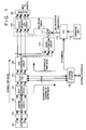
- Fig. 1 is a block diagram showing the arrangement of a signal processing circuit of a color copying machine according to the first embodiment of the present invention.
- reference numeral 101 denotes a CCD; 102, an A/D converter; 103, a shading correction circuit; 104, an input masking circuit; 105, a selector; 106, a LOG conversion circuit for achieving RGB ⁇ CMY conversion; 107, an output masking ⁇ UCR (undercolor removal) circuit; 108, a selector for selecting one of C', M', Y', and K' output from the output masking ⁇ UCR circuit 107 and outputting the selected color data to a printer (not shown) (since the printer frame-sequentially records C, M, Y, and K data); 110, a black extraction circuit for extracting K from C, M, and Y data; 109, an external I/F circuit; 111, a multiplier circuit; 112, a control CPU; and 113, an operation unit of this color copying machine.
- the selector 105 is used for switching the flow of an image signal in correspondence with a "normal copy mode” (when image data output from the CCD 101 is to be printed), a “scanner data external I/F output mode” (when image data output from the CCD 101 is output via the external I/F circuit 109), and an “external I/F print mode” (when image data supplied from the external I/F circuit 109 is to be output).
- Image pickup signals from the CCD 101 are converted into digital signals by the A/D converter 102, and the digital signals are subjected to correction of shading caused by a light amount nonuniformity of an optical system, a sensitivity variation in units of pixels of the CCD, and the like in the shading correction circuit 103.
- the corrected signals are subjected to masking processing using a matrix calculation in the input masking circuit 104.
- the processed signals are then input to the selector 105.
- the selector 105 In the "scanner data external I/F output mode", the selector 105 outputs image data (R, G, and B) from the CCD 101 to an external apparatus via the external I/F circuit 109.
- the selector 105 supplies the image data (R, G, and B) from the CCD 101 to the LOG conversion circuit 106.
- the LOG conversion circuit 106 performs RGB ⁇ CMY conversion (e.g., conversion using a table), and outputs three color signals C, M, and Y. These three color signals C, M, and Y are input to the output masking ⁇ UCR circuit 107, and are also input to the black extraction circuit 110.
- a K (black) signal extracted by the black extraction circuit 110 is also input to the output masking ⁇ UCR circuit 107 via the multiplier circuit 111 (to be described later).
- the black extraction circuit 110 outputs, e.g., min[C, M, Y] (a minimum value of the three signals C, M, and Y) as K.
- the output masking ⁇ UCR circuit 107 achieves an output masking calculation and an UCR (undercolor removal, i.e., subtracting a K signal component from color signals C, M, and Y) in a single matrix calculation.
- One of outputs C', M', Y', and K' from the output masking ⁇ UCR circuit 107 is selected by the selector 108, and is supplied to a printer which frame-sequentially prints color images.
- the selector 105 inputs image data (R, G, and B) from the external apparatus to the LOG conversion circuit 106, and the input data are supplied to the printer via the above-mentioned processing.
- the K signal extracted by the black extraction circuit 110 is input to the multiplier circuit 111, and a product of the K signal and a multiplication coefficient ⁇ from the CPU 112 obtained by the circuit 111 is input to the output masking ⁇ UCR circuit 107.
- the ratio of the K signal to the C, M, and Y signals can be varied by the multiplication coefficient ⁇ to be multiplied with the K signal.
- the value ⁇ can be changed by a command instruction input from the external apparatus via the external I/F circuit 109 or an instruction from the operation unit 113.
- the value ⁇ is set to be smaller than that set when image data output from the external apparatus is to be printed, thereby reducing K signal components which contribute to conspicuous "granularity", and eliminating the "granularity".
- the value ⁇ is set to be large to maintain high gray reproducibility (to prevent recording of gray with a color appearance).
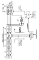
- Fig. 2 is a block diagram showing the arrangement of a signal processing circuit of a color copying machine according to the second embodiment.
- a K signal component extracted by the black extraction circuit 110 is multiplied with the multiplication coefficient ⁇ by the multiplier circuit 111, while in the second embodiment, a similar calculation is achieved by an output masking ⁇ UCR circuit 207.
- the output masking ⁇ UCR circuit 107 shown in Fig. 1 normally performs the following matrix calculation:
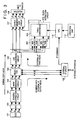
- Fig. 3 is a block diagram showing the arrangement of a signal processing circuit of a color copying machine according to the third embodiment.
- a black extraction circuit 310 shown in Fig. 3 extracts a K signal according to the following equation.
- min represents min(C, M, Y)
- max represents max(C, M, Y).
- K min ⁇ min/max + (1 - min/max)(min/255)2 ⁇
- equation (3-1) includes a division, it is difficult to achieve a high-speed hardware calculation.
- a MAX detection circuit 301 calculates max(C, M, Y)
- a MIN detection circuit 302 calculates min(C, M, Y)
- a table conversion circuit 303 performs a calculation according to equation (3-1).
- calculation contents according to equation (3-1) are written at the respective addresses by a calculation of the CPU 112 in advance.
- Fig. 4 is a block diagram showing the arrangement of a signal processing circuit of a color copying machine according to the fourth embodiment.
- the color appearance correction can be realized by changing matrix coefficients in an output masking ⁇ UCR circuit 407.
- matrix coefficients corresponding to a coefficient ⁇ 1 suitable for one with the least noise generation amount of the three scanners 411 to 413 are set in an output masking circuit 415.
- a result of multiplication by ⁇ 2 for compensating for the deficiency is given for a portion corresponding to the table conversion circuit 303 shown in Fig. 4, thus setting optimal values of ⁇ for all the scanners.
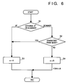
- Fig. 6 is a flow chart showing an example of the ⁇ setting operation of the CPU 112 in each of the first to fourth embodiments described above.
- step S1 it is checked in step S1 if a mode for printing image data from the external I/F circuit or a mode for printing image data read by a scanner is selected. If it is determined in step S1 that the mode for printing image data from the external I/F circuit is selected, a relatively small value A is set as the value ⁇ in step S3.
- step S2 in the normal copy mode for printing image data read by the scanner, it is checked in step S2 in accordance with an operation at the operation unit 113 if the apparatus is set in, e.g., a character copy (print) mode.
- A is set in ⁇ in step S3 described above.
- a value B sufficiently larger than A is set in ⁇ in step S4.
- the value ⁇ may be uniquely set to be A or B.
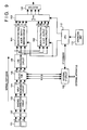
- Fig. 7 is a block diagram showing the arrangement of a signal processing circuit of a color copying machine according to the fifth embodiment of the present invention.
- the same reference numerals in Fig. 7 denote the same constituting elements as in Figs. 1 to 4.
- Reference numeral 507 denotes a black extraction circuit which can switch the calculation equation used in black extraction in accordance with an instruction from the CPU 112; and 510, an output masking ⁇ UCR circuit which can similarly switch the matrix coefficients in accordance with an instruction from the CPU 112.
- Fig. 8 is a table showing a black extraction method and output masking coefficients to be set in correspondence with each print method and each type (mode) of an image in the apparatus shown in Fig. 7. Mode setting processing operations in respective print methods will be described in turn below with reference to Fig. 8.
- it may be controlled to select a) when the output frequency of a C. G. image, characters, a map image, or the like is high.
- the black extraction circuit 510 and the output masking ⁇ UCR circuit 507 are realized by different circuits.
- an arrangement shown in Fig. 9 may be adopted.
- reference numerals 501 and 502 denote black extraction & output masking ⁇ UCR circuits A and B.
- One of the outputs from the circuits 501 and 502 is selected by a selector 503.
- the CPU 112 may control the selector 503 to select the output from the circuit 501 in the character image mode, and to select the output from the circuit 502 in the normal image mode. More specifically, the operation shown in Fig. 8 can be realized by the arrangement shown in Fig. 9 in the same manner as in the arrangement shown in Fig. 7.
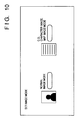
- the above-mentioned normal image mode and the character image mode are set and changed on a screen of the operation unit 113 shown in Fig. 10 or by a command from the external I/F circuit.
- Such an image mode switching operation may be performed in correspondence with each area obtained by dividing a single image.
- the normal image mode and the character image mode can be switched in units of areas in one image in correspondence with the contents (1 or 0) of the bit map memory 601.
- the contents of the bit map memory 601 can be set by the CPU 112.
- the contents may be set using the operation unit 113 or may be input using a tablet (not shown).
- black extraction & output masking ⁇ UCR operations may be performed in correspondence with a normal image, a character image, and a map image (although black extraction & output masking ⁇ UCR circuits are required).
- Fig. 12 shows, as a modification, a case wherein different output masking coefficients are set in correspondence with a map image mode, character image mode, CG image mode, and other image mode (a total of four modes) in the fifth to seventh embodiments.
- an optimal output masking coefficient can be set for each image mode.
- Fig. 13 shows an example of an image mode switching screen on the operation unit.
- the character image mode, the map image mode, and other image mode corresponding to a character/printed picture mode, a character/photographic paper picture mode, a printed picture mode, and a photographic paper picture mode in the example shown in Fig. 13; these modes are separated since they have different masking coefficients) can be selected.
- the "granularity" is improved by multiplying the K signal with the coefficient ⁇ or by switching the extraction equation itself.
- noise is prevented from being mixed in a K signal upon extraction of the K signal.
- high-frequency noise components are removed from C, M, and Y signals by three LPFs 501 shown in Fig. 14, and thereafter, the C, M, and Y signals are input to the black extraction circuit 110 to extract a K signal, so that noise in the K signal does not appear as granularity on an image.
- Delay circuits 502 shown in Fig. 14 compensate for the delay time of the LPFs 501.
- the LPF 501 is not limited to a first-order filter.
- the LPFs 501 are arranged at the input side of the black extraction circuit 110 shown in Fig. 14.
- an LPF 601 is arranged at the output side of the black extraction circuit 110. With this arrangement, the number of LPFs is decreased from three to one, and substantially the same effect as in the eighth embodiment can be expected.
- high-frequency noise components are removed by the LPFs.
- the present invention is not limited to this.
- a lower envelope detection circuit may be used.
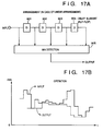
- Fig. 16 shows an example wherein lower envelope detection circuits 701 are used in place of the LPFs.
- Each of the lower envelope detection circuits 701 outputs the smallest pixel value of surrounding pixel values, as shown in, e.g., Fig. 17A, and has a function of removing high-frequency components as in the LPF, as can be understood from Fig. 17B.
- the reason why the lower envelope detection circuits are used in place of the LPFs is as follows. If a simple LPF is used, C, M, and Y signals higher than actual C, M, and Y signals are input to the black extraction circuit at an edge portion of an image, as indicated by a hatched portion in Fig. 18. The lower envelope detection circuits are used for preventing a K signal higher than an actual one from being extracted.
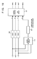
- Fig. 19 shows the 11th embodiment.
- a lower envelope detection circuit 801 is arranged at the output side of the black extraction circuit 110 as in the 10th embodiment.
- the number of lower envelope detection circuits can be decreased from three to one, and an equivalent effect can be expected.
- the present invention may be applied to either a system constituted by a plurality of devices or an apparatus consisting of a single device. Also, the present invention may be applied to a case wherein the invention is achieved by supplying a program to the system or apparatus.
- a K signal can be extracted without mixing a granularity component in the K signal, the granularity itself can be prevented from becoming conspicuous, and high gray reproducibility can be maintained.
Landscapes
- Engineering & Computer Science (AREA)
- Multimedia (AREA)
- Signal Processing (AREA)
- Color Image Communication Systems (AREA)
- Facsimile Image Signal Circuits (AREA)
- Color, Gradation (AREA)
- Color Electrophotography (AREA)
- Image Processing (AREA)
Abstract
Description
- The present invention relates to an image forming method and apparatus for printing out, e.g., image data output from a scanner and image data output from an external apparatus and, more particularly, to an apparatus for printing out color image data.
- As a color image forming apparatus for printing out image data output from, e.g., a scanner, a computer, or the like, a color copying machine has been conventionally proposed.
- Colors to be finally printed by a color copying machine are four colors, i.e., C, M, Y, and K, and the color copying machine performs signal processing for converting R, G, and B image data output from a scanner or an external apparatus such as a computer into C, M, Y, and K data.
- However, the conventional color copying machine suffers the following problems.
- Upon conversion from R, G, and B → C, M, Y, and K (LOG conversion, black extraction, output masking, UCR), when the UCR amount is large, the ratio of K becomes high as compared to the amounts of C, M, and Y on a gray (white/black) portion of an image. Especially on a highlight gray portion (light gray portion) in a "normal copy mode", the noise amount increases due to light shot noise on a CCD (which noise is proportional to a square of the amount of light incident on the CCD and becomes larger as the gray portion is lighter), and this noise is included in a K signal having the highest ratio of C, M, Y, and K data by black extraction and output masking·UCR processing. As a result, "granularity " of an image becomes conspicuous.
- It is empirically known that the "granularity" of an image can be eliminated by changing the coefficients used in the output masking·UCR processing to decrease the ratio of the K signal and to increase the ratios of the C, M, and Y signals. However, with this processing, when C. G. image data (including no noise) created by a computer is to be printed out via an external I/F, or when gray characters (character document or characters included in a map) are to be printed out even in a normal copy mode, the C, M, and Y colors on a gray (white/black) portion are recorded at relatively higher ratios, and the gray portion is printed in gray with a color appearance, thus impairing gray reproduction upon printing of a C. G. image.
- As a method of extracting a K signal from C, M, and Y signals, a scheme designed for optimizing K data in a C. G. image, a character document, and a character portion of a map document (further improving gray reproducibility) is available (to be described in detail in the embodiment of the present invention). However, such a new black extraction method has a nature of emphasizing a noise component in a normal natural image, thus posing another problem.
- It is a concern of the present invention to solve the conventional problems.
- It is another concern of the present invention to provide an image forming method which can achieve both high color reproducibility and high gray reproducibility when various images are input from various apparatuses.
- In accordance with an aspect of the present invention, there is provided an image forming apparatus comprising: (a) extraction means for extracting a black signal from an input color image signal; (b) changing means for changing a ratio of the black signal extracted by said extraction means to the color image signal in accordance with an input instruction; and (c) image forming means for performing an output operation in accordance with the black signal extracted by said extraction means and the color image signal. According to another aspect of the present invention, there is provided an image forming apparatus comprising: (a) a scanner for forming a color image signal by scanning an image; (b) extraction means for extracting a black signal from the color image signal; (c) removing means for removing a high-frequency component of the black signal extracted by said extraction means; and (d) image forming means for performing an output operation in accordance with the black signal, from which the high-frequency component is removed, and with the color image signal.
- Other advantages and features of the present invention will become apparent from the following detailed description of the embodiments of the present invention taken in conjunction with the accompanying drawings.
-
- Fig. 1 is a block diagram showing the arrangement of a signal processing circuit of a color copying machine according to the first embodiment of the present invention;
- Fig. 2 is a block diagram showing the arrangement of a signal processing circuit of a color copying machine according to the second embodiment of the present invention;
- Fig. 3 is a block diagram showing the arrangement of a signal processing circuit of a color copying machine according to the third embodiment of the present invention;
- Fig. 4 is a block diagram showing the arrangement of a signal processing circuit of a color copying machine according to the fourth embodiment of the present invention;
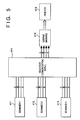
- Fig. 5 is a block diagram for explaining an example for setting optimal coefficients for a plurality of scanners;
- Fig. 6 is a flow chart for explaining a part of the operation of a
CPU 112 in the circuits shown in Figs. 1 to 4; - Fig. 7 is a block diagram showing the arrangement of a signal processing circuit of a color copying machine according to the fifth embodiment of the present invention;
- Fig. 8 is a table showing a black extraction method and output masking coefficients which are set in correspondence with each print method and each type (mode) of an image in the circuit shown in Fig. 7;
- Fig. 9 is a block diagram showing the arrangement of a signal processing circuit of a color copying machine according to the sixth embodiment of the present invention;
- Fig. 10 is a view showing an example of a mode setting operation screen of the copying machine according to the sixth embodiment;
- Fig. 11 is a block diagram showing the arrangement of a signal processing circuit of a color copying machine according to the seventh embodiment of the present invention;
- Fig. 12 is a table showing another example of a method of determining a black extraction method and output masking coefficients;
- Fig. 13 is a view showing another example of the mode setting operation screen;
- Fig. 14 is a block diagram showing the arrangement of principal part of a signal processing circuit according to the eighth embodiment of the present invention;
- Fig. 15 is a block diagram showing the arrangement of principal part of a signal processing circuit according to the ninth embodiment of the present invention;
- Fig. 16 is a block diagram showing the arrangement of principal part of a signal processing circuit according to the 10th embodiment of the present invention;
- Fig. 17A is a block diagram showing the detailed arrangement of a lower envelope detection circuit shown in Fig. 16;
- Fig. 17B is a waveform chart for explaining the operation of the circuit shown in Fig. 17A;
- Fig. 18 is a graph showing the input/output characteristics of a black extraction circuit shown in Figs. 14 and 15; and
- Fig. 19 is a block diagram showing the arrangement of principal part of a signal processing circuit according to the 11th embodiment of the present invention.
- The preferred embodiments of the present invention will be described in detail hereinafter with reference to the accompanying drawings.
- Fig. 1 is a block diagram showing the arrangement of a signal processing circuit of a color copying machine according to the first embodiment of the present invention.
- Referring to Fig. 1,
reference numeral 101 denotes a CCD; 102, an A/D converter; 103, a shading correction circuit; 104, an input masking circuit; 105, a selector; 106, a LOG conversion circuit for achieving RGB → CMY conversion; 107, an output masking·UCR (undercolor removal) circuit; 108, a selector for selecting one of C', M', Y', and K' output from the output masking·UCR circuit 107 and outputting the selected color data to a printer (not shown) (since the printer frame-sequentially records C, M, Y, and K data); 110, a black extraction circuit for extracting K from C, M, and Y data; 109, an external I/F circuit; 111, a multiplier circuit; 112, a control CPU; and 113, an operation unit of this color copying machine. Theselector 105 is used for switching the flow of an image signal in correspondence with a "normal copy mode" (when image data output from theCCD 101 is to be printed), a "scanner data external I/F output mode" (when image data output from theCCD 101 is output via the external I/F circuit 109), and an "external I/F print mode" (when image data supplied from the external I/F circuit 109 is to be output). - The signal processing of the color copying machine with the above-mentioned arrangement will be explained below.
- Image pickup signals from the
CCD 101 are converted into digital signals by the A/D converter 102, and the digital signals are subjected to correction of shading caused by a light amount nonuniformity of an optical system, a sensitivity variation in units of pixels of the CCD, and the like in theshading correction circuit 103. The corrected signals are subjected to masking processing using a matrix calculation in theinput masking circuit 104. The processed signals are then input to theselector 105. - In the "scanner data external I/F output mode", the
selector 105 outputs image data (R, G, and B) from theCCD 101 to an external apparatus via the external I/F circuit 109. - In the "normal copy mode", the
selector 105 supplies the image data (R, G, and B) from theCCD 101 to theLOG conversion circuit 106. TheLOG conversion circuit 106 performs RGB → CMY conversion (e.g., conversion using a table), and outputs three color signals C, M, and Y. These three color signals C, M, and Y are input to the output masking·UCR circuit 107, and are also input to theblack extraction circuit 110. A K (black) signal extracted by theblack extraction circuit 110 is also input to the output masking·UCR circuit 107 via the multiplier circuit 111 (to be described later). - The
black extraction circuit 110 outputs, e.g., min[C, M, Y] (a minimum value of the three signals C, M, and Y) as K. - The output masking·
UCR circuit 107 achieves an output masking calculation and an UCR (undercolor removal, i.e., subtracting a K signal component from color signals C, M, and Y) in a single matrix calculation. - One of outputs C', M', Y', and K' from the output masking·
UCR circuit 107 is selected by theselector 108, and is supplied to a printer which frame-sequentially prints color images. - In the "external I/F image data print mode", the
selector 105 inputs image data (R, G, and B) from the external apparatus to theLOG conversion circuit 106, and the input data are supplied to the printer via the above-mentioned processing. - The operation for eliminating any "granularity" of an image by changing the ratio of the extracted K signal in the above-mentioned color copying machine will be explained below.
- The K signal extracted by the
black extraction circuit 110 is input to themultiplier circuit 111, and a product of the K signal and a multiplication coefficient α from theCPU 112 obtained by thecircuit 111 is input to the output masking·UCR circuit 107. - Since the first embodiment adopts the above-mentioned arrangement, the ratio of the K signal to the C, M, and Y signals can be varied by the multiplication coefficient α to be multiplied with the K signal. The value α can be changed by a command instruction input from the external apparatus via the external I/
F circuit 109 or an instruction from theoperation unit 113. By a decision of a user himself or herself, when image data free from a noise component such as a character signal input from the external apparatus such as a computer is to be printed, the value α is set to be large (made close to "1") ; when image data output from a scanner is to be printed, the value α is set to be small (made close to "0"). Alternatively, when image data output from a scanner is to be printed, a predetermined optimal value α (which can eliminate granularity) is automatically set. - In this manner, when image data output from a scanner is to be printed, the value α is set to be smaller than that set when image data output from the external apparatus is to be printed, thereby reducing K signal components which contribute to conspicuous "granularity", and eliminating the "granularity". On the other hand, when external image data free from noise is to be printed, or when a character portion, a map, or the like of image data even from the scanner is to be printed, the value α is set to be large to maintain high gray reproducibility (to prevent recording of gray with a color appearance).
- The second embodiment which eliminates the "granularity" of an image by changing the ratio of an extracted K signal in a color copying machine will be described below.
- Fig. 2 is a block diagram showing the arrangement of a signal processing circuit of a color copying machine according to the second embodiment. In the first embodiment, a K signal component extracted by the
black extraction circuit 110 is multiplied with the multiplication coefficient α by themultiplier circuit 111, while in the second embodiment, a similar calculation is achieved by an output masking·UCR circuit 207. - The output masking·
UCR circuit 107 shown in Fig. 1 normally performs the following matrix calculation:
- Therefore, to also perform a multiplication of a K signal by α, the following calculation can be performed:

- In this manner, when the
CPU 112 sets the matrix coefficients in the output masking·UCR circuit 207, the same processing as in the first embodiment can be realized without using a multiplier circuit for multiplying a K signal with the multiplication coefficient α. - The third embodiment which eliminates the "granularity" of an image by changing the ratio of an extracted K signal in a color copying machine will be described below.
- Fig. 3 is a block diagram showing the arrangement of a signal processing circuit of a color copying machine according to the third embodiment. A
black extraction circuit 310 shown in Fig. 3 extracts a K signal according to the following equation. In the following equation, min represents min(C, M, Y), and max represents max(C, M, Y).
- In this equation, (min/max) is considered as a parameter "color appearance" {for example, since min and max values become close to each other on a gray portion, the value (min/max) becomes close to "1"; but since max >> min is satisfied as the gray portion has a color appearance, the value (min/max) becomes close to "0"}. Since a gray portion has a value (min/max) = 1, K becomes equal to min, i.e., min(C, M, Y), and becomes equal to the above-mentioned black extraction equation. More specifically, (min/max) is an amount indicating grayishness, and (min/255)² is an amount indicating darkishness. Note that (min/255)² can be replaced by (min/255) or (min/255)³.
- On the other hand, when an image portion has a strong color appearance, K becomes almost equal to min(min/255)². As a result, the extraction amount of K considerably decreases as compared to that obtained when K is equal to min(C, M, Y).
- This is based on the principle that gray reproducibility on a gray portion is improved by increasing the ratio of a K signal as much as possible, and color reproducibility on a portion with a strong color appearance is improved by decreasing the ratio of a K signal as much as possible.
- However, since equation (3-1) includes a division, it is difficult to achieve a high-speed hardware calculation. Thus, in practice, a
MAX detection circuit 301 calculates max(C, M, Y), aMIN detection circuit 302 calculates min(C, M, Y), and atable conversion circuit 303 performs a calculation according to equation (3-1). As the table contents of thetable conversion circuit 303, calculation contents according to equation (3-1) are written at the respective addresses by a calculation of theCPU 112 in advance. In this case, when theCPU 112 performs a calculation according to the following equation in place of equation (3-1), the same processing as in each of the above embodiments can be realized by changing the value of α:
- The fourth embodiment which eliminates the "granularity" of an image by changing the ratio of an extracted K signal in a color copying machine will be described below.
- Fig. 4 is a block diagram showing the arrangement of a signal processing circuit of a color copying machine according to the fourth embodiment. In the fourth embodiment, when the color appearance changes depending on the value of the coefficient α in equation (3-2) in the third embodiment, the color appearance correction can be realized by changing matrix coefficients in an output masking·UCR circuit 407.
- In this case, α = α₁·α₂ may be assumed, and a result of multiplication by α₁ may be set in the
table conversion circuit 303. With this arrangement, when a plurality ofscanners 411 to 413 are connected to asingle printer 416 via aselector 414 or a communication path, as shown in, e.g., Fig. 5, matrix coefficients corresponding to a coefficient α₁ suitable for one with the least noise generation amount of the threescanners 411 to 413 are set in anoutput masking circuit 415. When image data from another scanner is to be printed, a result of multiplication by α₂ for compensating for the deficiency is given for a portion corresponding to thetable conversion circuit 303 shown in Fig. 4, thus setting optimal values of α for all the scanners. - Fig. 6 is a flow chart showing an example of the α setting operation of the
CPU 112 in each of the first to fourth embodiments described above. - As shown in Fig. 6, it is checked in step S1 if a mode for printing image data from the external I/F circuit or a mode for printing image data read by a scanner is selected. If it is determined in step S1 that the mode for printing image data from the external I/F circuit is selected, a relatively small value A is set as the value α in step S3.
- On the other hand, in the normal copy mode for printing image data read by the scanner, it is checked in step S2 in accordance with an operation at the
operation unit 113 if the apparatus is set in, e.g., a character copy (print) mode. In the character copy mode, A is set in α in step S3 described above. On the other hand, if the character copy mode is not selected, a value B sufficiently larger than A is set in α in step S4. - In the flow chart shown in Fig. 6, depending on the mode for printing image data from the external I/F circuit or the copy mode for printing image data read by the scanner, the value α may be uniquely set to be A or B.
- Fig. 7 is a block diagram showing the arrangement of a signal processing circuit of a color copying machine according to the fifth embodiment of the present invention. The same reference numerals in Fig. 7 denote the same constituting elements as in Figs. 1 to 4.
Reference numeral 507 denotes a black extraction circuit which can switch the calculation equation used in black extraction in accordance with an instruction from theCPU 112; and 510, an output masking·UCR circuit which can similarly switch the matrix coefficients in accordance with an instruction from theCPU 112. - Fig. 8 is a table showing a black extraction method and output masking coefficients to be set in correspondence with each print method and each type (mode) of an image in the apparatus shown in Fig. 7. Mode setting processing operations in respective print methods will be described in turn below with reference to Fig. 8.
-
- a) When the character or map copy mode is selected in accordance with an instruction from the
operation unit 113 shown in Fig. 7, theCPU 112 performs a table setting operation for executing black extraction on the basis of equation (3-1) in theblack extraction circuit 510. At the same time, theCPU 112 sets matrix coefficients for setting a relatively high ratio of K (a relatively large UCR amount) in the output masking·UCR circuit 507.
With this operation, a print output with high gray reproducibility can be obtained for an original image such as characters, a map, or the like. - b) When the normal copy mode is selected in accordance with an instruction from the
operation unit 113, theCPU 112 performs a table setting operation for executing black extraction on the basis of min(C, M, Y) in theblack extraction circuit 510. At the same time, theCPU 112 sets matrix coefficients for setting a relatively low ratio of K (a relatively small UCR amount) in the output masking·UCR circuit 507.
With this operation, a print output free from granularity due to noise can be obtained for a normal natural image. Also, a print output free from moiré components can be obtained for a dot document. -
- a) When the mode for a C. G. image, characters, or a map is selected in accordance with an instruction from the
operation unit 113 shown in Fig. 7 or an I/F command from the external I/F circuit 109, theCPU 112 performs a table setting operation for executing black extraction on the basis of equation (3-1) in theblack extraction circuit 510. At the same time, theCPU 112 sets matrix coefficients for setting a relatively high ratio of K (a relatively large UCR amount) in the output masking·UCR circuit 507.
With this operation, gray reproducibility of a print output from an IPU such as a C. G. image, characters, a map image, or the like can be improved. - b) When the normal image mode is selected in accordance with an instruction from the
operation unit 113 shown in Fig. 7 or an I/F command from the external I/F circuit 109, theCPU 112 performs a table setting operation for executing black extraction on the basis of min(C, M, Y) in theblack extraction circuit 510. At the same time, theCPU 112 sets matrix coefficients for setting a relatively low ratio of K (a relatively small UCR amount) in the output masking·UCR circuit 507.
With this operation, even when natural image data (including a dot document) read from theCCD 101 via an IPU is to be printed out via the IPU again, an output image free from granularity or moiré components can be obtained. - When the print mode of an image from the IPU is selected in advance in accordance with an instruction from the
operation unit 113 shown in Fig. 7, one of the setting contents a) and b) of "[2] When Image From External I/F is Printed (Part 1)" is automatically selected. - In this case, it may be controlled to select a) when the output frequency of a C. G. image, characters, a map image, or the like is high.
- In the fifth embodiment shown in Fig. 7, the
black extraction circuit 510 and the output masking·UCR circuit 507 are realized by different circuits. For example, an arrangement shown in Fig. 9 may be adopted. Referring to Fig. 9,reference numerals circuits selector 503. - Therefore, if the black extraction & output masking·
UCR circuit A 501 is used for a character or map image, and the black extraction & output masking·UCR circuit B 502 is used for a normal image, theCPU 112 may control theselector 503 to select the output from thecircuit 501 in the character image mode, and to select the output from thecircuit 502 in the normal image mode. More specifically, the operation shown in Fig. 8 can be realized by the arrangement shown in Fig. 9 in the same manner as in the arrangement shown in Fig. 7. - The above-mentioned normal image mode and the character image mode are set and changed on a screen of the
operation unit 113 shown in Fig. 10 or by a command from the external I/F circuit. Such an image mode switching operation may be performed in correspondence with each area obtained by dividing a single image. - For example, in the arrangement shown in Fig. 11, when the contents of a
bit map memory 601 are read out in synchronism with an image signal, the normal image mode and the character image mode can be switched in units of areas in one image in correspondence with the contents (1 or 0) of thebit map memory 601. - The contents of the
bit map memory 601 can be set by theCPU 112. The contents may be set using theoperation unit 113 or may be input using a tablet (not shown). - If the number of bits of the bit map memory allows, different black extraction & output masking·UCR operations may be performed in correspondence with a normal image, a character image, and a map image (although black extraction & output masking·UCR circuits are required).
- Fig. 12 shows, as a modification, a case wherein different output masking coefficients are set in correspondence with a map image mode, character image mode, CG image mode, and other image mode (a total of four modes) in the fifth to seventh embodiments. Thus, an optimal output masking coefficient can be set for each image mode.
- Fig. 13 shows an example of an image mode switching screen on the operation unit. Thus, the character image mode, the map image mode, and other image mode (corresponding to a character/printed picture mode, a character/photographic paper picture mode, a printed picture mode, and a photographic paper picture mode in the example shown in Fig. 13; these modes are separated since they have different masking coefficients) can be selected.
- In the first to seventh embodiments described above, the "granularity" is improved by multiplying the K signal with the coefficient α or by switching the extraction equation itself. In the eighth to 11th embodiments to be described below, noise is prevented from being mixed in a K signal upon extraction of the K signal.
- More specifically, high-frequency noise components are removed from C, M, and Y signals by three
LPFs 501 shown in Fig. 14, and thereafter, the C, M, and Y signals are input to theblack extraction circuit 110 to extract a K signal, so that noise in the K signal does not appear as granularity on an image. - Delay
circuits 502 shown in Fig. 14 compensate for the delay time of theLPFs 501. Note that theLPF 501 is not limited to a first-order filter. - In the eighth embodiment, the
LPFs 501 are arranged at the input side of theblack extraction circuit 110 shown in Fig. 14. In the ninth embodiment, as shown in Fig. 15, anLPF 601 is arranged at the output side of theblack extraction circuit 110. With this arrangement, the number of LPFs is decreased from three to one, and substantially the same effect as in the eighth embodiment can be expected. - In the eighth and ninth embodiments, high-frequency noise components are removed by the LPFs. However, the present invention is not limited to this. For example, a lower envelope detection circuit may be used.
- Fig. 16 shows an example wherein lower
envelope detection circuits 701 are used in place of the LPFs. Each of the lowerenvelope detection circuits 701 outputs the smallest pixel value of surrounding pixel values, as shown in, e.g., Fig. 17A, and has a function of removing high-frequency components as in the LPF, as can be understood from Fig. 17B. - The reason why the lower envelope detection circuits are used in place of the LPFs is as follows. If a simple LPF is used, C, M, and Y signals higher than actual C, M, and Y signals are input to the black extraction circuit at an edge portion of an image, as indicated by a hatched portion in Fig. 18. The lower envelope detection circuits are used for preventing a K signal higher than an actual one from being extracted.
- Fig. 19 shows the 11th embodiment. In this embodiment, a lower
envelope detection circuit 801 is arranged at the output side of theblack extraction circuit 110 as in the 10th embodiment. - With this arrangement, the number of lower envelope detection circuits can be decreased from three to one, and an equivalent effect can be expected.
- Note that the present invention may be applied to either a system constituted by a plurality of devices or an apparatus consisting of a single device. Also, the present invention may be applied to a case wherein the invention is achieved by supplying a program to the system or apparatus.
- As described above, according to the present invention, when an image from a scanner or a C. G. image is to be printed out, optimal signal processing for removing granularity can be performed.
- Since a K signal can be extracted without mixing a granularity component in the K signal, the granularity itself can be prevented from becoming conspicuous, and high gray reproducibility can be maintained.
- The present invention is not limited to the above embodiments and various changes and modifications can be made within the spirit and scope of the present invention. Therefore, to apprise the public of the scope of the present invention the following claims are made.
Claims (28)
- An image forming apparatus comprising:(a) extraction means for extracting a black signal from an input color image signal;(b) changing means for changing a ratio of the black signal extracted by said extraction means to the color image signal in accordance with an input instruction; and(c) image forming means for performing an output operation in accordance with the black signal extracted by said extraction means and the color image signal.
- The apparatus according to claim 1, wherein said image forming means comprises image processing means for performing a matrix calculation for the black signal extracted by said extraction means and the color image signal.
- The apparatus according to claim 2, wherein said image processing means performs masking and UCR processing.
- The apparatus according to claim 2, wherein said changing means also changes a matrix coefficient of said image processing means in accordance with the instruction.
- The apparatus according to claim 1, wherein said changing means changes the ratio in correspondence with an input image signal from a scanner and an input image signal from an external apparatus.
- The apparatus according to claim 1, wherein said changing means changes the ratio in accordance with whether or not the image signal is an image signal in a character portion.
- The apparatus according to claim 1, wherein said changing means changes the ratio in accordance with a manual operation.
- The apparatus according to claim 1, wherein said changing means changes said extraction means in correspondence with a first mode in which the ratio of the black signal to be extracted changes in correspondence with a grayishness of the color image signal, and a second mode in which the ratio does not change.
- The apparatus according to claim 8, wherein said extraction means changes the ratio of the black signal to be extracted in accordance with a darkishness of the color image signal in the first mode.
- The apparatus according to claim 1, wherein said extraction means can extract the black signal using minimum and maximum values of a plurality of color signals constituting the color image signal.
- The apparatus according to claim 1, wherein said changing means changes a coefficient to be multiplied with the extracted black signal.
- An image forming apparatus comprising:(a) a scanner for forming a color image signal by scanning an image;(b) extraction means for extracting a black signal from the color image signal;(c) removing means for removing a high-frequency component of the black signal extracted by said extraction means; and(d) image forming means for performing an output operation in accordance with the black signal, from which the high-frequency component is removed, and with the color image signal.
- The apparatus according to claim 12, wherein said removing means comprises a low-pass filter.
- The apparatus according to claim 12, wherein said removing means comprises a detection circuit for detecting a lower envelope of the black signal.
- An image forming apparatus comprising:(a) extraction means for extracting a black signal from an input color image signal;(b) changing means for changing an extraction method of the black signal by said extraction means in accordance with an input instruction; and(c) image forming means for performing an output operation in accordance with the black signal extracted by said extraction means and the color image signal.
- The apparatus according to claim 15, wherein said image forming means comprises image processing means for performing a matrix calculation for the black signal extracted by said extraction means and the color image signal.
- The apparatus according to claim 16, wherein said changing means also changes a matrix coefficient of said image processing means in accordance with the instruction.
- The apparatus according to claim 15, wherein said image forming means comprises a UCR circuit which receives the black signal extracted by said extraction means and the color image signal.
- The apparatus according to claim 18, wherein said changing means also changes processing of said UCR circuit.
- The apparatus according to claim 15, wherein said image forming means comprises a masking circuit which receives the black signal extracted by said extraction means and the color image signal.
- The apparatus according to claim 20, wherein said changing means also changes processing of said masking circuit.
- An image forming apparatus comprising:(a) extraction means for extracting a black signal from an input color image signal;(b) UCR means for receiving the input color image signal and the black signal; and(c) interlocking means for interlocking changing of operations of said extraction means and said UCR means.
- An image forming apparatus comprising:(a) extraction means for extracting a black signal from an input color image signal;(b) masking means for receiving the input color image signal and the black signal; and(c) interlocking means for interlocking changing of operations of said extraction means and said masking means.
- An image forming apparatus comprising:(a) extraction means for extracting a black signal from an input color image signal;(b) matrix calculation means for receiving the input color image signal and the black signal; and(c) interlocking means for interlocking changing of operations of said extraction means and said matrix calculation means.
- An image forming apparatus comprising:(a) extraction means for extracting a black signal from an input color image signal; and(b) matrix calculation means for receiving the input color image signal and the black signal,
wherein the number of a plurality of operation modes of said matrix calculation means is larger than the number of a plurality of operation modes of said extraction means. - An image forming method comprising the steps of:(a) extracting a black signal from an input color image signal;(b) changing a ratio of the black signal extracted in the extraction step to the color image signal in accordance with an input instruction; and(c) performing an output operation in accordance with the black signal extracted in the extraction step and the color image signal.
- An image forming method comprising the steps of:(a) forming a color image signal by scanning an image;(b) extracting a black signal from the input color image signal;(c) removing a high-frequency component of the black signal extracted in the extraction step; and(d) performing an output operation in accordance with the black signal, from which the high-frequency component is extracted, and with the color image signal.
- An image forming method comprising the steps of:(a) extracting a black signal from an input color image signal;(b) changing an extraction method of the black signal in the extraction step in accordance with an input instruction; and(c) performing an output operation in accordance with the black signal extracted in the extraction step and the color image signal.
Applications Claiming Priority (6)
| Application Number | Priority Date | Filing Date | Title |
|---|---|---|---|
| JP1002494 | 1994-01-31 | ||
| JP1002494 | 1994-01-31 | ||
| JP10024/94 | 1994-01-31 | ||
| JP6064051A JPH07254994A (en) | 1994-01-31 | 1994-03-31 | Method and device for forming image |
| JP64051/94 | 1994-03-31 | ||
| JP6405194 | 1994-03-31 |
Publications (3)
| Publication Number | Publication Date |
|---|---|
| EP0665681A2 true EP0665681A2 (en) | 1995-08-02 |
| EP0665681A3 EP0665681A3 (en) | 1996-05-15 |
| EP0665681B1 EP0665681B1 (en) | 2003-01-02 |
Family
ID=26345180
Family Applications (1)
| Application Number | Title | Priority Date | Filing Date |
|---|---|---|---|
| EP95300559A Expired - Lifetime EP0665681B1 (en) | 1994-01-31 | 1995-01-30 | Color image forming method and apparatus with correction of the black component |
Country Status (4)
| Country | Link |
|---|---|
| US (1) | US6118558A (en) |
| EP (1) | EP0665681B1 (en) |
| JP (1) | JPH07254994A (en) |
| DE (1) | DE69529242T2 (en) |
Cited By (2)
| Publication number | Priority date | Publication date | Assignee | Title |
|---|---|---|---|---|
| WO2019172918A1 (en) * | 2018-03-08 | 2019-09-12 | Hewlett-Packard Development Company, L.P. | Processing of spot colors in a printing system |
| WO2021061089A1 (en) * | 2019-09-23 | 2021-04-01 | Hewlett-Packard Development Company, L.P. | Print agent coverage vectors |
Families Citing this family (7)
| Publication number | Priority date | Publication date | Assignee | Title |
|---|---|---|---|---|
| JP3262492B2 (en) | 1996-04-09 | 2002-03-04 | キヤノン株式会社 | Color printer control device, color printer control method, and storage medium storing control program |
| JP3584964B2 (en) * | 1999-10-14 | 2004-11-04 | 三菱電機株式会社 | Color conversion device and color conversion method |
| US7274489B2 (en) * | 2002-11-01 | 2007-09-25 | Kabushiki Kaisha Toshiba | Image forming apparatus and method of controlling the apparatus |
| US7626742B2 (en) * | 2005-02-16 | 2009-12-01 | Samsung Electronics Co., Ltd. | Color data conversion apparatus and method using gamut boundary descriptors |
| JP2007142901A (en) * | 2005-11-20 | 2007-06-07 | Fuji Xerox Co Ltd | Color image processing device, color image forming device, color image forming system, color image processing method, and color image forming method |
| JP4362139B2 (en) * | 2007-03-28 | 2009-11-11 | Okiセミコンダクタ株式会社 | Timing controller, liquid crystal display device, and liquid crystal display panel driving method |
| JP5036844B2 (en) * | 2010-04-15 | 2012-09-26 | シャープ株式会社 | Image compression apparatus, image output apparatus, image reading apparatus, image compression method, computer program, and recording medium |
Citations (6)
| Publication number | Priority date | Publication date | Assignee | Title |
|---|---|---|---|---|
| US4831409A (en) * | 1987-01-13 | 1989-05-16 | Ricoh Company, Ltd. | Color image processing system having an adjustable UCR function |
| EP0497325A2 (en) * | 1991-01-30 | 1992-08-05 | Fuji Photo Film Co., Ltd. | Method for determining amounts of UCR and image processing apparatus |
| EP0562596A2 (en) * | 1992-03-26 | 1993-09-29 | Canon Kabushiki Kaisha | Color image processing method and apparatus thereof |
| EP0665679A2 (en) * | 1994-01-27 | 1995-08-02 | Hewlett-Packard Company | Digital colour printer system |
| EP0665674A2 (en) * | 1994-01-27 | 1995-08-02 | Hewlett-Packard Company | Colour printer system |
| EP0665678A2 (en) * | 1994-01-27 | 1995-08-02 | Hewlett-Packard Company | Colour printer system |
Family Cites Families (8)
| Publication number | Priority date | Publication date | Assignee | Title |
|---|---|---|---|---|
| US4864391A (en) * | 1986-05-09 | 1989-09-05 | Canon Kabushiki Kaisha | Image processing apparatus for color correcting an image which can monitor the result of the color correction |
| JP3048151B2 (en) * | 1988-01-19 | 2000-06-05 | キヤノン株式会社 | Color image forming equipment |
| JP2754591B2 (en) * | 1988-09-12 | 1998-05-20 | ミノルタ株式会社 | Color copier and image forming method |
| US5128748A (en) * | 1989-02-15 | 1992-07-07 | Hitachi, Ltd. | Image processing system and apparatus for processing color documents |
| US5345320A (en) * | 1990-11-29 | 1994-09-06 | Minolta Camera Kabushiki Kaisha | Color image data processing apparatus comprising monochrome pixel detector |
| JPH0736609B2 (en) * | 1991-04-17 | 1995-04-19 | 富士ゼロックス株式会社 | Under color removal method of color image forming apparatus |
| JP3285941B2 (en) * | 1992-07-31 | 2002-05-27 | キヤノン株式会社 | Color processing method, color processing apparatus, and color image processing system |
| JPH0787346A (en) * | 1993-09-10 | 1995-03-31 | Fuji Xerox Co Ltd | Method and device for processing color picture |
-
1994
- 1994-03-31 JP JP6064051A patent/JPH07254994A/en active Pending
-
1995
- 1995-01-30 EP EP95300559A patent/EP0665681B1/en not_active Expired - Lifetime
- 1995-01-30 DE DE69529242T patent/DE69529242T2/en not_active Expired - Lifetime
- 1995-01-31 US US08/381,650 patent/US6118558A/en not_active Expired - Fee Related
Patent Citations (6)
| Publication number | Priority date | Publication date | Assignee | Title |
|---|---|---|---|---|
| US4831409A (en) * | 1987-01-13 | 1989-05-16 | Ricoh Company, Ltd. | Color image processing system having an adjustable UCR function |
| EP0497325A2 (en) * | 1991-01-30 | 1992-08-05 | Fuji Photo Film Co., Ltd. | Method for determining amounts of UCR and image processing apparatus |
| EP0562596A2 (en) * | 1992-03-26 | 1993-09-29 | Canon Kabushiki Kaisha | Color image processing method and apparatus thereof |
| EP0665679A2 (en) * | 1994-01-27 | 1995-08-02 | Hewlett-Packard Company | Digital colour printer system |
| EP0665674A2 (en) * | 1994-01-27 | 1995-08-02 | Hewlett-Packard Company | Colour printer system |
| EP0665678A2 (en) * | 1994-01-27 | 1995-08-02 | Hewlett-Packard Company | Colour printer system |
Cited By (3)
| Publication number | Priority date | Publication date | Assignee | Title |
|---|---|---|---|---|
| WO2019172918A1 (en) * | 2018-03-08 | 2019-09-12 | Hewlett-Packard Development Company, L.P. | Processing of spot colors in a printing system |
| US11126900B2 (en) | 2018-03-08 | 2021-09-21 | Hewlett-Packard Development Company, L.P. | Processing of spot colors in a printing system |
| WO2021061089A1 (en) * | 2019-09-23 | 2021-04-01 | Hewlett-Packard Development Company, L.P. | Print agent coverage vectors |
Also Published As
| Publication number | Publication date |
|---|---|
| JPH07254994A (en) | 1995-10-03 |
| DE69529242T2 (en) | 2003-09-04 |
| US6118558A (en) | 2000-09-12 |
| DE69529242D1 (en) | 2003-02-06 |
| EP0665681A3 (en) | 1996-05-15 |
| EP0665681B1 (en) | 2003-01-02 |
Similar Documents
| Publication | Publication Date | Title |
|---|---|---|
| EP0963106B1 (en) | Background noise removal for a low-cost digital color copier | |
| JP4067532B2 (en) | Color conversion apparatus, image forming apparatus, color conversion method, computer program, and recording medium | |
| US6192152B1 (en) | Image processing apparatus | |
| US8041112B2 (en) | Image processing apparatus, image forming apparatus, image reading apparatus, image processing method, image processing program, computer-readable storage medium for storing the image processing program with segmentation and density correction optimization | |
| US5886797A (en) | Method and apparatus for controlling a spatial filtering process based on characteristics of image data | |
| US8130410B2 (en) | Image processing method, image processing apparatus, image forming system and recording medium readable by a computer | |
| JP2756280B2 (en) | Color image processing equipment | |
| US6226397B1 (en) | Image processing using different image sizes depending on whether the processing is color or monochrome | |
| JP2003153006A (en) | Image processing apparatus | |
| JP2007150607A (en) | Image processor, image forming apparatus, image processing method, image processing program, and its recording medium | |
| US5508823A (en) | Image processing method and apparatus | |
| JP3334042B2 (en) | IMAGE PROCESSING APPARATUS, IMAGE READING APPARATUS AND IMAGE FORMING APPARATUS EQUIPPED WITH THE SAME, IMAGE PROCESSING METHOD, AND COMPUTER-READABLE STORAGE MEDIUM CONTAINING IMAGE PROCESSING PROCEDURE | |
| EP0665681B1 (en) | Color image forming method and apparatus with correction of the black component | |
| JP2003219191A (en) | Image processor and image forming apparatus comprising it | |
| JP3179528B2 (en) | Color image processing apparatus and method | |
| US6178010B1 (en) | Image processing device | |
| JPH10283470A (en) | Image processor, image processing method and recording medium | |
| JP2010278933A (en) | Image processing device, image forming device, image processing method, program and recording medium | |
| JPH02244876A (en) | Sharpness improving system for picture processor | |
| JP3093217B2 (en) | Image processing apparatus and image processing method | |
| JPH0877350A (en) | Image processor | |
| JP2951972B2 (en) | Image processing device | |
| JP3888119B2 (en) | Image processing device | |
| JP2951977B2 (en) | Image processing device | |
| JP2004104248A (en) | Image processing apparatus, image reader, image forming apparatus, and image processing method |
Legal Events
| Date | Code | Title | Description |
|---|---|---|---|
| PUAI | Public reference made under article 153(3) epc to a published international application that has entered the european phase |
Free format text: ORIGINAL CODE: 0009012 |
|
| AK | Designated contracting states |
Kind code of ref document: A2 Designated state(s): DE FR GB IT |
|
| PUAL | Search report despatched |
Free format text: ORIGINAL CODE: 0009013 |
|
| AK | Designated contracting states |
Kind code of ref document: A3 Designated state(s): DE FR GB IT |
|
| 17P | Request for examination filed |
Effective date: 19960925 |
|
| 17Q | First examination report despatched |
Effective date: 19980615 |
|
| GRAH | Despatch of communication of intention to grant a patent |
Free format text: ORIGINAL CODE: EPIDOS IGRA |
|
| RTI1 | Title (correction) |
Free format text: COLOR IMAGE FORMING METHOD AND APPARATUS WITH CORRECTION OF THE BLACK COMPONENT |
|
| GRAH | Despatch of communication of intention to grant a patent |
Free format text: ORIGINAL CODE: EPIDOS IGRA |
|
| GRAA | (expected) grant |
Free format text: ORIGINAL CODE: 0009210 |
|
| AK | Designated contracting states |
Kind code of ref document: B1 Designated state(s): DE FR GB IT |
|
| REG | Reference to a national code |
Ref country code: GB Ref legal event code: FG4D Free format text: 20030102 |
|
| REF | Corresponds to: |
Ref document number: 69529242 Country of ref document: DE Date of ref document: 20030206 Kind code of ref document: P |
|
| ET | Fr: translation filed | ||
| PLBE | No opposition filed within time limit |
Free format text: ORIGINAL CODE: 0009261 |
|
| STAA | Information on the status of an ep patent application or granted ep patent |
Free format text: STATUS: NO OPPOSITION FILED WITHIN TIME LIMIT |
|
| 26N | No opposition filed |
Effective date: 20031003 |
|
| PGFP | Annual fee paid to national office [announced via postgrant information from national office to epo] |
Ref country code: IT Payment date: 20110120 Year of fee payment: 17 Ref country code: FR Payment date: 20110209 Year of fee payment: 17 Ref country code: DE Payment date: 20110131 Year of fee payment: 17 |
|
| PGFP | Annual fee paid to national office [announced via postgrant information from national office to epo] |
Ref country code: GB Payment date: 20110125 Year of fee payment: 17 |
|
| GBPC | Gb: european patent ceased through non-payment of renewal fee |
Effective date: 20120130 |
|
| REG | Reference to a national code |
Ref country code: FR Ref legal event code: ST Effective date: 20120928 |
|
| PG25 | Lapsed in a contracting state [announced via postgrant information from national office to epo] |
Ref country code: DE Free format text: LAPSE BECAUSE OF NON-PAYMENT OF DUE FEES Effective date: 20120801 Ref country code: GB Free format text: LAPSE BECAUSE OF NON-PAYMENT OF DUE FEES Effective date: 20120130 |
|
| REG | Reference to a national code |
Ref country code: DE Ref legal event code: R119 Ref document number: 69529242 Country of ref document: DE Effective date: 20120801 |
|
| PG25 | Lapsed in a contracting state [announced via postgrant information from national office to epo] |
Ref country code: IT Free format text: LAPSE BECAUSE OF NON-PAYMENT OF DUE FEES Effective date: 20120130 |
|
| PG25 | Lapsed in a contracting state [announced via postgrant information from national office to epo] |
Ref country code: FR Free format text: LAPSE BECAUSE OF NON-PAYMENT OF DUE FEES Effective date: 20120131 |