EP0632627B1 - Communication device - Google Patents
Communication device Download PDFInfo
- Publication number
- EP0632627B1 EP0632627B1 EP94304604A EP94304604A EP0632627B1 EP 0632627 B1 EP0632627 B1 EP 0632627B1 EP 94304604 A EP94304604 A EP 94304604A EP 94304604 A EP94304604 A EP 94304604A EP 0632627 B1 EP0632627 B1 EP 0632627B1
- Authority
- EP
- European Patent Office
- Prior art keywords
- processing
- frame
- communication
- data
- address
- Prior art date
- Legal status (The legal status is an assumption and is not a legal conclusion. Google has not performed a legal analysis and makes no representation as to the accuracy of the status listed.)
- Expired - Lifetime
Links
Images


Classifications
-
- H—ELECTRICITY
- H04—ELECTRIC COMMUNICATION TECHNIQUE
- H04L—TRANSMISSION OF DIGITAL INFORMATION, e.g. TELEGRAPHIC COMMUNICATION
- H04L49/00—Packet switching elements
- H04L49/90—Buffering arrangements
-
- H—ELECTRICITY
- H04—ELECTRIC COMMUNICATION TECHNIQUE
- H04L—TRANSMISSION OF DIGITAL INFORMATION, e.g. TELEGRAPHIC COMMUNICATION
- H04L9/00—Cryptographic mechanisms or cryptographic arrangements for secret or secure communications; Network security protocols
- H04L9/40—Network security protocols
Definitions
- the present invention relates to a communication device for use in communication between, for example, programmable controllers.
- Fig. 5A shows one constitutional embodiment of a system using such control and Fig. 5B shows the constitution of frames in this system, while Fig. 6 shows frame formats of the token and data in this system.
- a plurality of stations 10 to which station numbers 12, 13, 14 ... are attached are connected to a communication line 11.
- Each station 10 acquires a data transmission right, when it has received the token addressed to itself from another station via the communication line 11.
- the station 10 which has acquired the data transmission right transmits the data through the communication line 12 to other stations, and then transmits the token to the next station 10 via the communication line 12 after the data transmission has finished.
- the token is circulated through the respective stations 10 to carry out acquisition and transfer of the transmission right, whereby the collision of the data on the communication line 11 can be prevented.
- a frame regarding the data which are transmitted among the respective stations 10 is usually called an LLC (logical link control) data frame, and another frame regarding the control of a medium (the communication line 11 ), such as the token, is called an MAC (media access control) frame.
- the station 10 having the station number 12 acquires the token.
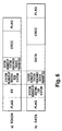
- the frame regarding the token has flags (each 1 byte) regarding HDLC (high level data link control) procedure at the head and tail thereof, and it further contains a hexadecimal code (EX wherein X is optional) denoting the token, the station number of the destination station, the station number of the station from which the transmission is made, and CRC (cyclic redundancy check) code (each 1 byte).
- EX hexadecimal code
- station number 12 which station number 12 has received is, a frame regarding the token transmitted from the station number 11 to the station number 12, and so the station number 12 acquires the token.
- the station number 12 which has acquired the token transmits the data in the form of a frame shown in Fig. 5 B b).
- the frame regarding the data as shown in Fig. 6 b), has flags regarding the HDLC procedure at the head and tail thereof, and it further contains the station number of the destination station, the station number of the station from which the transmission is made, the data and the CRC code.
- station number 12 transfers the transmission right to station number 13 by transmitting the token in the form of a frame shown in Fig. 5 B c).
- the station number 13 which has acquired the token transmits the data in the form of a frame shown in Fig. 5 B d), and then transmits the token in the form of a frame shown in Fig. 5 B e) to the next station, i.e., station number 14.
- each station 10 has a function for judging whether or not the frame regarding the token or the data received via the communication line 11 is addressed to itself. For example, as shown in Japanese Patent Application Laid-open No. Hei 3-44236, the judgement as to whether or not the frame is addressed to that station can be made by software processing.
- an interrupt is often generated to processing means (CPU) constituting the respective stations, so that the throughput of the processing means disadvantageously deteriorates. That is, the frame transmitted through the communication line is received by a single receiving channel of each station, and in compliance with this receive action, the interrupt is generated to the processing means, such as a CPU.
- the CPU checks the address region of a predetermined position (e.g., the second byte in an embodiment in Fig. 6) of the received frame by software means. As a result of this check, only when the information stored in this address region corresponds to its own station number or a specific address (EX) representing the token, does the CPU execute processes corresponding to the data or the token. If the information stored in this address region does not correspond to its own station number or the specific address regarding the token, the processing means discontinues the receiving operation or abandons the received data.
- a predetermined position e.g., the second byte in an embodiment in Fig. 6
- EX specific address
- the interrupt must be generated to check the station number even in the case of the frame regarding the data or the token for a different station, and because of this, performance has been noticeably poor.
- EP-A-0064347 which described a communication device including a processor and a communication controller in which the communication controller checks the address region of received data frames and only when the information stored in this address region corresponds to its own station number does the communication controller interrupt the processor to analyse the frame communication data.
- This system avoids interrupting the processor to check the station number even where the frame is intended for a different station but it is not capable of operating in systems employing MAC frames.
- Objects of the present invention are to relieve the load on the progressing means and to improve processing performance of a device by inhibiting the generation of an interrupt request to the processing means in the case that a frame regarding a received token or data is addressed to a different station and to allow the device to respond both an LLC data frame and an MAC data frame.
- this invention provides a communication device used as at least one of a plurality of stations constituting a communication network, the communication device comprising:
- the interrupt processing is requested from the processing means, only when the frame received from the communication medium meets predetermined conditions.
- This condition is that the frame received from the communication medium is the LLC data frame addressed to that station or is the MAC frame which all the stations taking part in the communication generally receive. That is, the interrupt processing is requested from the processing means, only when the LLC data frame addressed to that station, or the MAC frame is received.
- the reason why such processing is possible is that the first and second channels are provided as communication channels in one station or communication device and it is judged by each communication channel whether or not the interrupt is necessary. That is, since the need for the interrupt is judged by each channel, it is no longer necessary to interrupt the processing means with the frame which need not be processed by that station, so that the processing performance of the whole device can be improved.
- the necessity of the interrupt is judged by comparing a destination address contained in the frame on the communication medium with first and second reference addresses set by the processing means.
- first reference address a specific address indicating the MAC frame is set
- second reference address an own station address, inherent in the each station itself, is set.
- the destination address is separated from the MAC frame, and this destination address is then compared with the first reference address to judge whether or not the received frame is the MAC frame.
- the destination address is separated from the LLC data frame, and this destination address is then compared with the second reference address to judge whether or not the received frame is the LLC data frame addressed to that station.
- the communication device of the present invention can be used for communication between application control devices such as programmable controllers.
- the processing means executes usual processing inclusive of reception and transmission of commands and data between the processing means and the application device as well as the analysis of the commands and data.
- the processing means discontinues the usual processing and executes reception processing.
- reception processing there are conducted at least the extraction of the data from the received frame and the processing of the preparation for the subsequent reception processing.
- Fig. 1 is a block diagram showing the constitution of a communication device regarding one embodiment of the present invention.
- Fig. 2 is a block diagram showing the constitution of a communication control section and a CPU in the embodiment of Fig. 1.
- Figs. 3A and 3B are flow charts showing the operation sequence of the communication control section in the embodiment of Fig. 1.
- Fig. 4 is a flow chart showing the operation sequence of the CPU in the embodiment of Fig. 1.
- Fig. 5A shows one exemplary constitution of a system involving control by a token.
- Fig. 5B shows the constitution of frames.
- Fig. 6 shows one example of each frame format of the token and data.
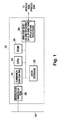
- Fig. 1 shows the constitution of a communication device 16 regarding one embodiment of the present invention in which an LSI for communication is mounted as a communication control section 14.
- the communication device 16 shown in this drawing can be used as each station 10 in the system constitution in Fig. 5A, and it is connected to a communication line 18.
- This communication device 16 is constituted of a modulation/demodulation section 20, a communication control section 14, a data storage section 22, a CPU 24, a ROM 26 and an area 28 for sending and receiving data to and from an application processor.
- the modulation/demodulation section 20 demodulates a frame regarding a token or data from a signal input through the communication line 18 at the time of receiving, and feeds the demodulated frame to the communication control section 14.
- This communication control section 14 detects an address from the frame demodulated by the modulation/demodulation section 20, and then generates an interrupt request to the CPU 24, if this address meets certain conditions.
- the CPU responds to this request to discontinue the processing, and then stores the information constituting the frame received via the modulation/demodulation section 20 in the data storage section 22.
- the ROM 26 is memory means for storing the operation program of the CPU 24.
- the area 28 for sending and receiving the data to and from the application processor is a memory area for sending and receiving communication data to and from the application processor, for example, a processor of a programmable controller.
- the CPU 24 carries out predetermined processing on the received information stored in the data storage section 22, and then writes the processed information into the area 28 for sending and receiving the data to and from the application processor.
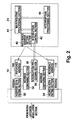
- Fig. 2 shows the constitution of the communication control section 14 and the CPU 24 in this embodiment.
- the communication control section 14 is equipped with two receiving channels RXDA1 and RXDA2. These receiving channels RXDA1 and RXDA2 are both connected to the communication line 18 via the modulation/demodulation section 20.
- the receiving channel RXDA1 is constituted of an address separating section 30 and an address comparing section 32
- the receiving channel RXDA2 is constituted of an address separating section 34 and an address comparing section 36.
- the communication control section 14 further has an interrupt processing section 38.
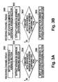
- Figs. 3A, 3B and 4 show the operation sequence of the communication control section 14 and the CPU 24 in this embodiment.
- each of the address separating sections 30 and 34 extracts the address region of the frame demodulated by the modulation/demodulation section 20, for example, the second byte of a frame constitution shown in Fig. 6 (step 202 or 302).
- Each of the address comparing sections 32 and 36 compares an address separated by the corresponding address separating section 30 or 34 with a reference address 100 or 110 (step 204 or 304).
- the station number of that actual station is set. Therefore, by the processing of the step 204, it is detected that the information demodulated by the modulation/demodulation section 20 is the token, and by the processing of the step 304, it is detected that the information is the data addressed to that particular station.
- an interrupt request is generated to the CPU 24 by the interrupt processing section 38 in the subsequent step 206 or 306.
- the CPU 24 discontinues the processing of a main routine and starts the interrupt processing. That is, when the interrupt request is generated by the interruption processing section 38, an interrupt control section 42 of the CPU 24 switches the processing from a main routine processing section 44 to an interrupt processing section 46.
- the CPU 24 executes the main routine shown in Fig. 4. That is, it carries out data exchange with an application region (400), the analysis of commands from the application region (402), the delivery of a response to the application region (404), and the analysis and processing of the received data (406).
- the interrupt request is generated by the interrupt processing section 38 of the communication control section 14
- the processing of the main routine is discontinued by the operation of the interrupt control section 42, and the processing of the interrupt processing section 46, i.e., interrupt processings shown by numerals 500 to 504 in Fig. 4 are conducted.
- the received data are read from the data storage section 22 by the CPU 24, and in the step 502, a receiving completion processing and preparation for the next receiving are conducted.
- the interrupt processing ends and the processing returns to the main routine.
- the address search of a frame regarding a token and data is conducted by the use of a plurality of channels of the receiving channels RXDA1 and RXDA2, and therefore it is no longer necessary for the CPU 24 to execute the judgement processing as to whether or not the frame is addressed to that station itself by software means.
- a look-up table system is established by the decrease of interrupt frequency and the simplification of an interrupt processing content, and owing to this look-up table system, there can be obtained effects such as the load relief of the CPU 24 and the improvement of processing performance of the whole device.
- these receiving channels RXDA1 and RXDA2 can be used as hardware (in an exclusive state).
- priority can be assigned, and for example, the interrupt of the token can have priority over the interrupt of the data.
Description
- The present invention relates to a communication device for use in communication between, for example, programmable controllers.
- As a technique for preventing transmitted data from colliding on a communication medium in a network constituting a plurality of communication devices (stations), there is, for example, control by a token. Fig. 5A shows one constitutional embodiment of a system using such control and Fig. 5B shows the constitution of frames in this system, while Fig. 6 shows frame formats of the token and data in this system.
- In the system shown in Fig. 5A, a plurality of
stations 10 to whichstation numbers communication line 11. Eachstation 10 acquires a data transmission right, when it has received the token addressed to itself from another station via thecommunication line 11. Thestation 10 which has acquired the data transmission right transmits the data through thecommunication line 12 to other stations, and then transmits the token to thenext station 10 via thecommunication line 12 after the data transmission has finished. As is apparent from the foregoing, in the data transmission system using token passing, the token is circulated through therespective stations 10 to carry out acquisition and transfer of the transmission right, whereby the collision of the data on thecommunication line 11 can be prevented. A frame regarding the data which are transmitted among therespective stations 10 is usually called an LLC (logical link control) data frame, and another frame regarding the control of a medium (the communication line 11 ), such as the token, is called an MAC (media access control) frame. - For example, when having received a frame shown in Fig. 5 B a), the
station 10 having thestation number 12 acquires the token. As shown generically in Fig. 6 a), the frame regarding the token has flags (each 1 byte) regarding HDLC (high level data link control) procedure at the head and tail thereof, and it further contains a hexadecimal code (EX wherein X is optional) denoting the token, the station number of the destination station, the station number of the station from which the transmission is made, and CRC (cyclic redundancy check) code (each 1 byte). The frame shown in Fig. 5 B a), whichstation number 12 has received is, a frame regarding the token transmitted from thestation number 11 to thestation number 12, and so thestation number 12 acquires the token. Thestation number 12 which has acquired the token transmits the data in the form of a frame shown in Fig. 5 B b). The frame regarding the data, as shown in Fig. 6 b), has flags regarding the HDLC procedure at the head and tail thereof, and it further contains the station number of the destination station, the station number of the station from which the transmission is made, the data and the CRC code. After having transmitted the data in the form of the frame shown in Fig. 5 B b),station number 12 transfers the transmission right tostation number 13 by transmitting the token in the form of a frame shown in Fig. 5 B c). Thestation number 13 which has acquired the token transmits the data in the form of a frame shown in Fig. 5 B d), and then transmits the token in the form of a frame shown in Fig. 5 B e) to the next station, i.e.,station number 14. - In order to achieve the above-mentioned control by the use of the token, each
station 10 has a function for judging whether or not the frame regarding the token or the data received via thecommunication line 11 is addressed to itself. For example, as shown in Japanese Patent Application Laid-open No. Hei 3-44236, the judgement as to whether or not the frame is addressed to that station can be made by software processing. - However, in the conventional technique having such a constitution, an interrupt is often generated to processing means (CPU) constituting the respective stations, so that the throughput of the processing means disadvantageously deteriorates. That is, the frame transmitted through the communication line is received by a single receiving channel of each station, and in compliance with this receive action, the interrupt is generated to the processing means, such as a CPU. Responding to the interrupt request, the CPU checks the address region of a predetermined position (e.g., the second byte in an embodiment in Fig. 6) of the received frame by software means. As a result of this check, only when the information stored in this address region corresponds to its own station number or a specific address (EX) representing the token, does the CPU execute processes corresponding to the data or the token. If the information stored in this address region does not correspond to its own station number or the specific address regarding the token, the processing means discontinues the receiving operation or abandons the received data.
- As described above, in the conventional technique, the interrupt must be generated to check the station number even in the case of the frame regarding the data or the token for a different station, and because of this, performance has been noticeably poor.
- Another technique is shown in EP-A-0064347 which described a communication device including a processor and a communication controller in which the communication controller checks the address region of received data frames and only when the information stored in this address region corresponds to its own station number does the communication controller interrupt the processor to analyse the frame communication data. This system avoids interrupting the processor to check the station number even where the frame is intended for a different station but it is not capable of operating in systems employing MAC frames.
- Objects of the present invention are to relieve the load on the progressing means and to improve processing performance of a device by inhibiting the generation of an interrupt request to the processing means in the case that a frame regarding a received token or data is addressed to a different station and to allow the device to respond both an LLC data frame and an MAC data frame.
- In a first aspect, this invention provides a communication device used as at least one of a plurality of stations constituting a communication network, the communication device comprising:
- processing means for conducting communication processing; and
- interrupt means for requesting interrupt processing from the processing means; the interrupt means including;
- a first communication channel, in connection with a communication medium, for judging whether or not a frame received through the communication medium is a logical link control data frame for data transmission addressed to the communication device by comparing a destination address contained in the frame with a first reference address; and characterised by further comprising;
- a second communication channel, in connection with the communication medium, for judging whether or not the frame received through the communication medium is a media access control frame for the maintenance and control of normal communication addressed to all stations including the communication device by comparing a destination address contained in the frame with a second reference address; and
- interrupt request means for requesting, from the processing means, the interruption processing regarding the media access control frame in the case that the frame received through the communication medium is judged to be the media access control frame by the second communication channel, or the interrupt processing regarding the logical link control data frame in the case that the frame received through the communication medium is judged to be the logical link control data frame by the first communication channel.
-
- In the present invention, the interrupt processing is requested from the processing means, only when the frame received from the communication medium meets predetermined conditions. This condition is that the frame received from the communication medium is the LLC data frame addressed to that station or is the MAC frame which all the stations taking part in the communication generally receive. That is, the interrupt processing is requested from the processing means, only when the LLC data frame addressed to that station, or the MAC frame is received. The reason why such processing is possible is that the first and second channels are provided as communication channels in one station or communication device and it is judged by each communication channel whether or not the interrupt is necessary. That is, since the need for the interrupt is judged by each channel, it is no longer necessary to interrupt the processing means with the frame which need not be processed by that station, so that the processing performance of the whole device can be improved.
- The necessity of the interrupt is judged by comparing a destination address contained in the frame on the communication medium with first and second reference addresses set by the processing means. As the first reference address, a specific address indicating the MAC frame is set, and as the second reference address, an own station address, inherent in the each station itself, is set. In the first communication channel, the destination address is separated from the MAC frame, and this destination address is then compared with the first reference address to judge whether or not the received frame is the MAC frame. In the second communication channel, the destination address is separated from the LLC data frame, and this destination address is then compared with the second reference address to judge whether or not the received frame is the LLC data frame addressed to that station.
- Furthermore, the communication device of the present invention can be used for communication between application control devices such as programmable controllers. In such a use, when no interruption request is generated, the processing means executes usual processing inclusive of reception and transmission of commands and data between the processing means and the application device as well as the analysis of the commands and data. Once the interrupt processing is requested, the processing means discontinues the usual processing and executes reception processing. In the reception processing, there are conducted at least the extraction of the data from the received frame and the processing of the preparation for the subsequent reception processing.
- Fig. 1 is a block diagram showing the constitution of a communication device regarding one embodiment of the present invention.
- Fig. 2 is a block diagram showing the constitution of a communication control section and a CPU in the embodiment of Fig. 1.
- Figs. 3A and 3B are flow charts showing the operation sequence of the communication control section in the embodiment of Fig. 1.
- Fig. 4 is a flow chart showing the operation sequence of the CPU in the embodiment of Fig. 1.
- Fig. 5A shows one exemplary constitution of a system involving control by a token.
- Fig. 5B shows the constitution of frames.
- Fig. 6 shows one example of each frame format of the token and data.
- Next, the present invention will be described in detail with reference to suitable examples. The present invention can be carried out in accordance with a system constituted as shown in Fig. 5A, and therefore in the following description, symbols in Fig. 5A will also be referred to.
- Fig. 1 shows the constitution of a
communication device 16 regarding one embodiment of the present invention in which an LSI for communication is mounted as acommunication control section 14. - The
communication device 16 shown in this drawing can be used as eachstation 10 in the system constitution in Fig. 5A, and it is connected to acommunication line 18. Thiscommunication device 16 is constituted of a modulation/demodulation section 20, acommunication control section 14, adata storage section 22, aCPU 24, aROM 26 and anarea 28 for sending and receiving data to and from an application processor. The modulation/demodulation section 20 demodulates a frame regarding a token or data from a signal input through thecommunication line 18 at the time of receiving, and feeds the demodulated frame to thecommunication control section 14. Thiscommunication control section 14 detects an address from the frame demodulated by the modulation/demodulation section 20, and then generates an interrupt request to theCPU 24, if this address meets certain conditions. The CPU responds to this request to discontinue the processing, and then stores the information constituting the frame received via the modulation/demodulation section 20 in thedata storage section 22. TheROM 26 is memory means for storing the operation program of theCPU 24. Thearea 28 for sending and receiving the data to and from the application processor, is a memory area for sending and receiving communication data to and from the application processor, for example, a processor of a programmable controller. TheCPU 24 carries out predetermined processing on the received information stored in thedata storage section 22, and then writes the processed information into thearea 28 for sending and receiving the data to and from the application processor. - Fig. 2 shows the constitution of the
communication control section 14 and theCPU 24 in this embodiment. - As shown in this drawing, the
communication control section 14 is equipped with two receiving channels RXDA1 and RXDA2. These receiving channels RXDA1 and RXDA2 are both connected to thecommunication line 18 via the modulation/demodulation section 20. The receiving channel RXDA1 is constituted of anaddress separating section 30 and anaddress comparing section 32, and the receiving channel RXDA2 is constituted of anaddress separating section 34 and anaddress comparing section 36. Thecommunication control section 14 further has an interruptprocessing section 38. - Figs. 3A, 3B and 4 show the operation sequence of the
communication control section 14 and theCPU 24 in this embodiment. As shown in Figs. 3A and 3B, each of theaddress separating sections demodulation section 20, for example, the second byte of a frame constitution shown in Fig. 6 (step 202 or 302). Each of theaddress comparing sections address separating section reference address 100 or 110 (step 204 or 304). As thereference address address setting section 40 of theCPU 24, prior to thestep 202 to 302 (step 200 or 300). That is, as thereference address 100 regarding the receiving channel RXDA1, EX denoting the token is set, and as thereference address 110 regarding the receiving channel RXDA2, the station number of that actual station is set. Therefore, by the processing of thestep 204, it is detected that the information demodulated by the modulation/demodulation section 20 is the token, and by the processing of thestep 304, it is detected that the information is the data addressed to that particular station. When the detection is made in thestep CPU 24 by the interruptprocessing section 38 in thesubsequent step - In compliance with this interrupt request, the
CPU 24 discontinues the processing of a main routine and starts the interrupt processing. That is, when the interrupt request is generated by theinterruption processing section 38, an interruptcontrol section 42 of theCPU 24 switches the processing from a mainroutine processing section 44 to an interruptprocessing section 46. - Concretely, before the occurrence of the interruption, the
CPU 24 executes the main routine shown in Fig. 4. That is, it carries out data exchange with an application region (400), the analysis of commands from the application region (402), the delivery of a response to the application region (404), and the analysis and processing of the received data (406). When the interrupt request is generated by the interruptprocessing section 38 of thecommunication control section 14, the processing of the main routine is discontinued by the operation of the interruptcontrol section 42, and the processing of the interruptprocessing section 46, i.e., interrupt processings shown bynumerals 500 to 504 in Fig. 4 are conducted. In thestep 500, the received data are read from thedata storage section 22 by theCPU 24, and in thestep 502, a receiving completion processing and preparation for the next receiving are conducted. In thestep 504, the interrupt processing ends and the processing returns to the main routine. - As described above, in the present embodiment, the address search of a frame regarding a token and data is conducted by the use of a plurality of channels of the receiving channels RXDA1 and RXDA2, and therefore it is no longer necessary for the
CPU 24 to execute the judgement processing as to whether or not the frame is addressed to that station itself by software means. Thus, a look-up table system is established by the decrease of interrupt frequency and the simplification of an interrupt processing content, and owing to this look-up table system, there can be obtained effects such as the load relief of theCPU 24 and the improvement of processing performance of the whole device. Furthermore, these receiving channels RXDA1 and RXDA2 can be used as hardware (in an exclusive state). In addition, priority can be assigned, and for example, the interrupt of the token can have priority over the interrupt of the data.
Claims (3)
- A communication device (16) used as at least one of a plurality of stations constituting a communication network, the communication device (16) comprising:processing means (24) for conducting communication processing; andinterrupt means (14) for requesting interrupt processing from the processing means (24); the interrupt means (14) including;a first communication channel (RXDA2), in connection with a communication medium (18), for judging whether or not a frame received through the communication medium (18) is a logical link control data frame for data transmission addressed to the communication device by comparing a destination address contained in the frame with a first reference address (110); and characterised by further comprising;a second communication channel (RXDA1), in connection with the communication medium (18), for judging whether or not the frame received through the communication medium (18) is a media access control frame for the maintenance and control of communication addressed to all stations including the communication device by comparing a destination address contained in the frame with a second reference address (100); andinterrupt request means (38) for requesting, from the processing means (24), the interruption processing regarding the media access control frame in the case that the frame received through the communication medium (18) is judged to be the media access control frame by the second communication channel (RXDA1), or the interrupt processing regarding the logical link control data frame in the case that the frame received through the communication medium (18) is judged to be the logical link control data frame by the first communication channel (RXDA2).
- The communication device (16) according to claim 1 wherein;the second communication channel (RXDA1) has means (30) for separating the destination address from the frame received through the communication medium (18), and means (32) for comparing the destination address with the second reference address (100) to judge whether or not the frame received through the communication medium (18) is the media access control frame;the first communication channel (RXDA2) has means (34) for separating the destination address from the frame received through the communication medium (18), means (36) for comparing the destination address with the first reference address (110) to judge whether the frame received through the communication medium (18) is the logical link control data frame addressed to the communication device; andthe processing means (24) has means (40) for setting a specific address indicating the media access control frame to the second reference address (100), and for setting a communication device address inherent in the communication device to the first reference address (110).
- The communication device according to claim 1 or 2 wherein the processing means (24) has:first processing routine means (44) for conducting processing inclusive of reception and transmission of commands and data between the processing means and an application device as well as the analysis of the commands and data;second processing routine means (46) for conducting reception processing inclusive of the extraction of the data from the frame received through the communication medium (18) and the processing of preparation for the next reception processing; andcontrol means (44) for discontinuing the processing by the first processing routine means (44) and conducting the reception processing by the second processing routine means (46), when the interrupt processing is requested.
Applications Claiming Priority (3)
| Application Number | Priority Date | Filing Date | Title |
|---|---|---|---|
| JP159884/93 | 1993-06-30 | ||
| JP15988493A JP3168102B2 (en) | 1993-06-30 | 1993-06-30 | Communication device |
| JP15988493 | 1993-06-30 |
Publications (3)
| Publication Number | Publication Date |
|---|---|
| EP0632627A2 EP0632627A2 (en) | 1995-01-04 |
| EP0632627A3 EP0632627A3 (en) | 1995-01-25 |
| EP0632627B1 true EP0632627B1 (en) | 2001-04-11 |
Family
ID=15703296
Family Applications (1)
| Application Number | Title | Priority Date | Filing Date |
|---|---|---|---|
| EP94304604A Expired - Lifetime EP0632627B1 (en) | 1993-06-30 | 1994-06-24 | Communication device |
Country Status (6)
| Country | Link |
|---|---|
| US (1) | US5724029A (en) |
| EP (1) | EP0632627B1 (en) |
| JP (1) | JP3168102B2 (en) |
| KR (1) | KR0131996B1 (en) |
| AU (1) | AU665492B2 (en) |
| DE (1) | DE69427053T2 (en) |
Families Citing this family (3)
| Publication number | Priority date | Publication date | Assignee | Title |
|---|---|---|---|---|
| KR100440444B1 (en) * | 2001-11-06 | 2004-07-15 | 에스케이 텔레콤주식회사 | Method for Communication between Master and Slave in Basestation |
| JP4369467B2 (en) * | 2006-12-12 | 2009-11-18 | 富士通株式会社 | Data relay apparatus, storage apparatus, and data relay method |
| WO2019155892A1 (en) | 2018-02-09 | 2019-08-15 | 株式会社オートネットワーク技術研究所 | Armrest |
Family Cites Families (11)
| Publication number | Priority date | Publication date | Assignee | Title |
|---|---|---|---|---|
| US4441162A (en) | 1981-04-22 | 1984-04-03 | Pitney Bowes Inc. | Local network interface with control processor & DMA controller for coupling data processing stations to common serial communications medium |
| GB8606217D0 (en) * | 1986-03-13 | 1986-04-16 | Univ Strathclyde | Local area network priority control system |
| NL8702394A (en) * | 1987-10-08 | 1989-05-01 | Philips Nv | INTERFACE FOR A CONNECTION NETWORK BETWEEN SEPARATE STATIONS ON THE ONE PART AND A PHYSICAL MEDIUM USED FOR MESSAGE TRANSMISSION BETWEEN THESE STATIONS. |
| US4937815A (en) * | 1988-11-21 | 1990-06-26 | Systech Corporation | Interrupt prioritization system and method for a demand shared bus |
| JPH0344236A (en) | 1989-07-12 | 1991-02-26 | Matsushita Electric Ind Co Ltd | Lan terminal equipment |
| JP2885834B2 (en) * | 1989-07-12 | 1999-04-26 | フクダ電子株式会社 | Communication system and communication control method |
| JPH03127104A (en) * | 1989-10-13 | 1991-05-30 | Hitachi Ltd | Data link device of programmable controller |
| JPH04108238A (en) * | 1990-08-28 | 1992-04-09 | Matsushita Electric Works Ltd | Collision control system at terminal equipment of network |
| JP2530060B2 (en) * | 1991-01-17 | 1996-09-04 | 株式会社東芝 | Communication control device |
| US5175732A (en) * | 1991-02-15 | 1992-12-29 | Standard Microsystems Corp. | Method and apparatus for controlling data communication operations within stations of a local-area network |
| US5276681A (en) * | 1992-06-25 | 1994-01-04 | Starlight Networks | Process for fair and prioritized access to limited output buffers in a multi-port switch |
-
1993
- 1993-06-30 JP JP15988493A patent/JP3168102B2/en not_active Expired - Fee Related
-
1994
- 1994-06-24 DE DE69427053T patent/DE69427053T2/en not_active Expired - Fee Related
- 1994-06-24 EP EP94304604A patent/EP0632627B1/en not_active Expired - Lifetime
- 1994-06-27 AU AU65993/94A patent/AU665492B2/en not_active Ceased
- 1994-06-30 KR KR1019940015387A patent/KR0131996B1/en not_active IP Right Cessation
-
1995
- 1995-10-17 US US08/544,211 patent/US5724029A/en not_active Expired - Fee Related
Also Published As
| Publication number | Publication date |
|---|---|
| AU665492B2 (en) | 1996-01-04 |
| EP0632627A2 (en) | 1995-01-04 |
| US5724029A (en) | 1998-03-03 |
| EP0632627A3 (en) | 1995-01-25 |
| AU6599394A (en) | 1995-01-12 |
| DE69427053D1 (en) | 2001-05-17 |
| KR950002281A (en) | 1995-01-04 |
| KR0131996B1 (en) | 1998-04-21 |
| DE69427053T2 (en) | 2001-11-15 |
| JPH07143143A (en) | 1995-06-02 |
| JP3168102B2 (en) | 2001-05-21 |
Similar Documents
| Publication | Publication Date | Title |
|---|---|---|
| US4507782A (en) | Method and apparatus of packet switching | |
| US7602779B2 (en) | Microprocessor, network system and communication method | |
| EP0851623B1 (en) | Multiplex transmission system | |
| US4825204A (en) | Address setting and data transmission system | |
| EP0742659A2 (en) | Multiple access system and method for multiple access | |
| US5197067A (en) | Packet communication system using a telephone switching network and a data flow control method | |
| US5892759A (en) | Data transmission control system for performing one-to-multiple site data transmission by the use of radio packet communication | |
| EP0580938B1 (en) | Duplex communication control device | |
| EP0632627B1 (en) | Communication device | |
| US5056090A (en) | Data transmission apparatus to be connected to multiplexed transmission line | |
| US6778497B1 (en) | Data communication control method for a network | |
| CA2025496C (en) | Packet communication system using a telephone switching network and a data flow control method | |
| US7231574B2 (en) | Hardware mechanism for receiving frames from a link | |
| JPS5986940A (en) | Information transmitting system of multi-drop system | |
| US6813727B2 (en) | Control unit having a main microprocessor and having a processor interface to a bus transceiver unit | |
| EP0507540A2 (en) | Method for operating a networked computer system to minimize data conversion overhead | |
| JP4570753B2 (en) | Error code sending apparatus and method | |
| US5638449A (en) | Data transmission installation of the radio network type, and corresponding process | |
| KR20000042907A (en) | Method for dealing with error of received packet in media access control layer of ethernet | |
| JP2650317B2 (en) | Broadcast control method in wireless communication system | |
| KR100208229B1 (en) | Packet service apparatus having parallel structure for interfacing digital service unit in a switching system | |
| JP2616727B2 (en) | Wireless local area network method | |
| KR0154485B1 (en) | Interrupt handling method of high level serial communication expanding chip board | |
| JP2601914B2 (en) | Data transmission equipment | |
| JP2743880B2 (en) | Broadcast message duplicate reception prevention function method |
Legal Events
| Date | Code | Title | Description |
|---|---|---|---|
| PUAI | Public reference made under article 153(3) epc to a published international application that has entered the european phase |
Free format text: ORIGINAL CODE: 0009012 |
|
| PUAL | Search report despatched |
Free format text: ORIGINAL CODE: 0009013 |
|
| 17P | Request for examination filed |
Effective date: 19940704 |
|
| AK | Designated contracting states |
Kind code of ref document: A2 Designated state(s): DE GB |
|
| AK | Designated contracting states |
Kind code of ref document: A3 Designated state(s): DE GB |
|
| 17Q | First examination report despatched |
Effective date: 19980213 |
|
| GRAG | Despatch of communication of intention to grant |
Free format text: ORIGINAL CODE: EPIDOS AGRA |
|
| GRAG | Despatch of communication of intention to grant |
Free format text: ORIGINAL CODE: EPIDOS AGRA |
|
| GRAH | Despatch of communication of intention to grant a patent |
Free format text: ORIGINAL CODE: EPIDOS IGRA |
|
| GRAH | Despatch of communication of intention to grant a patent |
Free format text: ORIGINAL CODE: EPIDOS IGRA |
|
| GRAA | (expected) grant |
Free format text: ORIGINAL CODE: 0009210 |
|
| AK | Designated contracting states |
Kind code of ref document: B1 Designated state(s): DE GB |
|
| REF | Corresponds to: |
Ref document number: 69427053 Country of ref document: DE Date of ref document: 20010517 |
|
| REG | Reference to a national code |
Ref country code: GB Ref legal event code: IF02 |
|
| PLBE | No opposition filed within time limit |
Free format text: ORIGINAL CODE: 0009261 |
|
| STAA | Information on the status of an ep patent application or granted ep patent |
Free format text: STATUS: NO OPPOSITION FILED WITHIN TIME LIMIT |
|
| 26N | No opposition filed | ||
| PGFP | Annual fee paid to national office [announced via postgrant information from national office to epo] |
Ref country code: DE Payment date: 20070621 Year of fee payment: 14 |
|
| PGFP | Annual fee paid to national office [announced via postgrant information from national office to epo] |
Ref country code: GB Payment date: 20070620 Year of fee payment: 14 |
|
| GBPC | Gb: european patent ceased through non-payment of renewal fee |
Effective date: 20080624 |
|
| PG25 | Lapsed in a contracting state [announced via postgrant information from national office to epo] |
Ref country code: DE Free format text: LAPSE BECAUSE OF NON-PAYMENT OF DUE FEES Effective date: 20090101 |
|
| PG25 | Lapsed in a contracting state [announced via postgrant information from national office to epo] |
Ref country code: GB Free format text: LAPSE BECAUSE OF NON-PAYMENT OF DUE FEES Effective date: 20080624 |