EP0615385B1 - Subband color video coding - Google Patents
Subband color video coding Download PDFInfo
- Publication number
- EP0615385B1 EP0615385B1 EP94301498A EP94301498A EP0615385B1 EP 0615385 B1 EP0615385 B1 EP 0615385B1 EP 94301498 A EP94301498 A EP 94301498A EP 94301498 A EP94301498 A EP 94301498A EP 0615385 B1 EP0615385 B1 EP 0615385B1
- Authority
- EP
- European Patent Office
- Prior art keywords
- subband
- image signal
- spatio
- temporal
- coding
- Prior art date
- Legal status (The legal status is an assumption and is not a legal conclusion. Google has not performed a legal analysis and makes no representation as to the accuracy of the status listed.)
- Expired - Lifetime
Links
Images


Classifications
-
- H—ELECTRICITY
- H04—ELECTRIC COMMUNICATION TECHNIQUE
- H04N—PICTORIAL COMMUNICATION, e.g. TELEVISION
- H04N19/00—Methods or arrangements for coding, decoding, compressing or decompressing digital video signals
- H04N19/90—Methods or arrangements for coding, decoding, compressing or decompressing digital video signals using coding techniques not provided for in groups H04N19/10-H04N19/85, e.g. fractals
- H04N19/94—Vector quantisation
-
- H—ELECTRICITY
- H04—ELECTRIC COMMUNICATION TECHNIQUE
- H04N—PICTORIAL COMMUNICATION, e.g. TELEVISION
- H04N19/00—Methods or arrangements for coding, decoding, compressing or decompressing digital video signals
- H04N19/10—Methods or arrangements for coding, decoding, compressing or decompressing digital video signals using adaptive coding
- H04N19/169—Methods or arrangements for coding, decoding, compressing or decompressing digital video signals using adaptive coding characterised by the coding unit, i.e. the structural portion or semantic portion of the video signal being the object or the subject of the adaptive coding
- H04N19/186—Methods or arrangements for coding, decoding, compressing or decompressing digital video signals using adaptive coding characterised by the coding unit, i.e. the structural portion or semantic portion of the video signal being the object or the subject of the adaptive coding the unit being a colour or a chrominance component
-
- H—ELECTRICITY
- H04—ELECTRIC COMMUNICATION TECHNIQUE
- H04N—PICTORIAL COMMUNICATION, e.g. TELEVISION
- H04N19/00—Methods or arrangements for coding, decoding, compressing or decompressing digital video signals
- H04N19/60—Methods or arrangements for coding, decoding, compressing or decompressing digital video signals using transform coding
- H04N19/61—Methods or arrangements for coding, decoding, compressing or decompressing digital video signals using transform coding in combination with predictive coding
-
- H—ELECTRICITY
- H04—ELECTRIC COMMUNICATION TECHNIQUE
- H04N—PICTORIAL COMMUNICATION, e.g. TELEVISION
- H04N19/00—Methods or arrangements for coding, decoding, compressing or decompressing digital video signals
- H04N19/60—Methods or arrangements for coding, decoding, compressing or decompressing digital video signals using transform coding
- H04N19/62—Methods or arrangements for coding, decoding, compressing or decompressing digital video signals using transform coding by frequency transforming in three dimensions
-
- H—ELECTRICITY
- H04—ELECTRIC COMMUNICATION TECHNIQUE
- H04N—PICTORIAL COMMUNICATION, e.g. TELEVISION
- H04N19/00—Methods or arrangements for coding, decoding, compressing or decompressing digital video signals
- H04N19/60—Methods or arrangements for coding, decoding, compressing or decompressing digital video signals using transform coding
- H04N19/63—Methods or arrangements for coding, decoding, compressing or decompressing digital video signals using transform coding using sub-band based transform, e.g. wavelets
- H04N19/64—Methods or arrangements for coding, decoding, compressing or decompressing digital video signals using transform coding using sub-band based transform, e.g. wavelets characterised by ordering of coefficients or of bits for transmission
- H04N19/645—Methods or arrangements for coding, decoding, compressing or decompressing digital video signals using transform coding using sub-band based transform, e.g. wavelets characterised by ordering of coefficients or of bits for transmission by grouping of coefficients into blocks after the transform
-
- H—ELECTRICITY
- H04—ELECTRIC COMMUNICATION TECHNIQUE
- H04N—PICTORIAL COMMUNICATION, e.g. TELEVISION
- H04N19/00—Methods or arrangements for coding, decoding, compressing or decompressing digital video signals
- H04N19/10—Methods or arrangements for coding, decoding, compressing or decompressing digital video signals using adaptive coding
- H04N19/102—Methods or arrangements for coding, decoding, compressing or decompressing digital video signals using adaptive coding characterised by the element, parameter or selection affected or controlled by the adaptive coding
- H04N19/115—Selection of the code volume for a coding unit prior to coding
-
- H—ELECTRICITY
- H04—ELECTRIC COMMUNICATION TECHNIQUE
- H04N—PICTORIAL COMMUNICATION, e.g. TELEVISION
- H04N19/00—Methods or arrangements for coding, decoding, compressing or decompressing digital video signals
- H04N19/10—Methods or arrangements for coding, decoding, compressing or decompressing digital video signals using adaptive coding
- H04N19/134—Methods or arrangements for coding, decoding, compressing or decompressing digital video signals using adaptive coding characterised by the element, parameter or criterion affecting or controlling the adaptive coding
- H04N19/146—Data rate or code amount at the encoder output
Description
- This invention relates to methods of coding a color component of an image signal sequence.
- Good quality, low bit rate color video coding is required for such applications as video teleconferencing over existing and future networks, as well as CD-ROM storage. An effective low rate coder should remove the redundancies due to temporal and spatial correlations along with perceptually irrelevant components of an image sequence.
- Subband digital coding techniques are well known in the art. See, e.g., N.S. Jayant and P. Noll, Digital Coding of Waveforms: Principles and Applications to Speech and Video (1984).
- Subband coding techniques have been used for image coding in a three-dimensional spatio-temporal subband framework as described in G. Karlsson and M. Vetterli, Three Dimensional Subband Coding of Video, Proceedings ICASSP (1988), 1100-1103. The technique described there employs multidimensional filtering to generate spatio-temporal frequency bands or subbands using so called quadrature mirror filters. These latter filters are described, e.g., in J.D. Johnston, A Filter Family Designed for Use in Quadrature Mirror Filter Bands, Proceedings ICASSP (1980).
- An MIMD architecture developed for the realtime implementation of three-dimensional subband coders is described in J. Hartung, Architecture for the Real-Time Implementation of Three-Dimensional Subband Video Coding, Proceedings ICASSP (1992), 225-228. A subband coding algorithm consists of filtering the original sequence into critically sampled subbands which are quantized and transmitted to a decoder. The decomposition into subbands is accomplished by temporal, horizontal, and vertical filtering into only high and low bands, respectively. A decoder dequantizes and filters the received data through related filters to reconstruct the image sequence.
- The allocation of channel bandwidth among multiple video coders that are processing in parallel various areas of a single image is described in EP-A-0479432A3. A video splitter is used to split successive images of a video signal using spatial decomposition or, alternatively, using a subband frequency decomposition. A video coder is used to reconstruct the images.
- US-A-4,817,182 discloses the analysis of image data in a number of iterated analysis procedures, using two-dimensional quadrature mirror filters to separate low-pass spatial filter response components and three differently oriented high-pass spatial filter response components.
- EP-A-0450937A3 discloses a geometric vector quantizer coding technique based on a three-dimensional subband framework. The original image data is decomposed into different spatial-temporal frequency bands and, based on the data in each band, different quantization strategies are applied to the bands. The subband which contains the lowest spatial-temporal frequency components is coded with high quality, while the non-dominant subbands are quantized using a low bit rate vector quantization method incorporating a structured codebook.
- According to this invention there is provided a method as claimed in
claim 1. - The present invention takes advantage of a three-dimensional subband framework by providing a technique for coding a color component of an image signal sequence with use of a first quantity of bits. The color component may be, for example the U or V component of the standard YUV color video format. The image signal sequence comprises a plurality of image signals.
- In an illustrative way of performing the invention, a color component of an image signal sequence is filtered into a plurality of subband image signals with use of a three-dimensional subband filter bank. One or more pixel signals ("pixels") of a first subband image signal are coded using one or more bits of the first quantity of bits. The first subband reflects the original image structure.
- A second quantity of bits is provided for coding one or more pixels of a second subband image signal. The second quantity of bits comprises one or more bits of the first quantity which were not used in coding pixels of the first subband image signal. The second subband reflects motion information of objects in the color component of the image signal sequence. The one or more pixels of the second subband image signal are coded with one or more bits of the second quantity.
- A third quantity of bits is provided for coding one or more pixels of additional subband image signals. This third quantity of bits comprises one or more bits not used in coding pixels of either the first or second subbands. In addition, this third quantity may be shared for use in coding pixels of more than one subband. For example, one or more bits of this third quantity of bits may be used to code one or more pixels of subband image signals reflecting substantially vertical and horizontal edges of moving image objects, respectively.
-
- Figure 1 presents an illustrative digital image coder;
- Figure 2 presents an illustrative subband filter arrangement in the coder of Figure 1;
- Figure 3 presents a graphical representation of the subbands provided by the subband filter presented in Figure 2; and
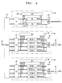
- Figure 4 presents an illustrative digital image decoder.
-
- For clarity of explanation, the illustrative coder is presented as comprising individual functional blocks (including functional blocks labeled as "processors"). The functions these blocks represent may be provided through the use of either shared or dedicated hardware, including, but not limited to, hardware capable of executing software. For example, the functions of processors presented in Figure 1 may be provided by a single shared processor. (Use of the term "processor" should not be construed to refer exclusively to hardware capable of executing software.)
- Illustrative embodiments may comprise digital signal processor (DSP) hardware, such as the AT&T DSP16 or DSP32C, read-only memory (ROM) for storing software performing the operations discussed below, and random access memory (RAM) for storing DSP results. Very large scale integration (VLSI) hardware embodiments, as well as custom VLSI circuitry in combination with a general purpose DSP circuit, may also be provided.
- Figure 1 presents an illustrative digital color image coder.
- The coder receives video signals in the standard YUV color video format at a rate of 15 frames per second and codes the signals for transmission over
channel 45 to a receiver/decoder. The YUV color video format comprises three signal components: one component (designated the "Y" component) representing luminance (or gray scale) video information, and two components (designated the "U" and "V" components) representing chrominance (or color) video information. The embodiment of Figure 1 includes threecoding sections section channel 45. The total bandwidth available to the embodiment for communication of video overchannel 45 is 368 kilobits per second (kbps) (an additional 16 kbps is available to code speech/audio information). Channel 45 may comprise a telecommunications network and/or a storage medium. -
Section 1 of the embodiment receives a sequence ofluminance frames 3 for coding. Each frame is a luminance image of the video sequence. Each such luminance frame comprises 240×360 pixel signals ("pixels"). For purposes of the present discussion, the sequence of luminance frames may be coded with, e.g., the first illustrative embodiment described in United States Patent Application Serial No. 07/832,256, (corresponding to EP-A-0555016, published 11 August 1993). - For purposes of consistency the numerals identifying components of the
first coding section 1 are the same as those used in the referenced application. As described in the referenced application,coding section 1 employs adaptive bit allocation together with conditional replenishment and quantization based on PCM with a uniform quantizer or Geometric Vector Quantization (GVQ). Of the 368 kbps available to the embodiment, 328 kbps is reserved for luminance coding bysection 1. - In addition to
coding section 1, the embodiment of Figure 1 comprisescoding sections coding section 10 receives asequence 13 of frames of the U component, whilecoding section 20 receives asequence 23 of frames of the V component. Each frame of the U and V components received bycoding sections samplers 30.Coding sections -
Coding sections section 10 and the U component. Nevertheless, what is described in terms ofsection 10 and the U component is applicable tosection 20 and the V component. - Turning to the structure and operation of
coding section 10, the sequence of down-sampled U frames are provided tosubband filter bank 12. As shown in Figure 2,filterbank 12 comprises a cascade of high-pass (HP) and low-pass (LP) temporal (t), horizontal spatial (h), and vertical spatial (v) filters. The two temporal filters, HPt and LPt, of theillustrative filterbank 12 comprise 2-tap Haar filters. These filters operate by forming difference and average frame signals, respectively, of consecutive chrominance frames received by thefilterbank 12.Filter bank 12 includes memory, e.g., RAM (not shown), coupled to the temporal filters, sufficient for storing frames of the chrominance signal sequence. - The vertical and horizontal spatial HP and LP filters which form the balance of the
filterbank 12 comprise 10-tap one-dimensional quadrature mirror filters (QMFs), of the type described in J. D. Johnston, A Filter Family Designed for Use in Quadrature Mirror Filter Banks, Proceedings ICASSP (1980). - The subband framework provided by
filterbank 12 may be represented graphically as shown in Figure 3. The large square on the left represents all subbands which are obtained from an initial low-pass temporal filtering. The individual subbands are numbered to correspond to those of Figure 2. The large square on the right represents all subbands which are obtained from an initial high-pass temporal filtering. For each given set of subbands under high- or low-pass temporal filtering, the horizontal direction is indicative of horizontal spatial filtering (from high-pass on the left to low-pass on the right) and the vertical direction is indicative of vertical spatial filtering (from high-pass at the top to low-pass at the bottom). As in Figure 2, the terms HP and LP refer to high-pass filtering and low-pass filtering respectively, while the subscripts t, h, and v refer to temporal, horizontal and vertical filtering respectively. - Each subband image contains temporal and spatial frequencies defined by the
filterbank 12. According to the illustrative embodiment, certain high spatiotemporal frequency subbands are discarded due to their general perceptual insignificance.Subbands bit allocation processor 14 ofcoding section 10. - Subband image quantization by quantizers 16 is performed responsive to an illustrative dynamic bit allocation (DBA) by
DBA processor 14. DBA has two significant parts. The first part is the ordering of the remaining subbands based on their perceptual significance. In this regard, a subband reflecting the original image structure, such as the lowest spatio-temporal frequency subband, i.e.,subband 1, is treated as the most perceptually significant. As a result,subband 1 is coded in a very accurate fashion. All bits available for coding a frame of chrominance information are made available for coding this subband image (generally, a given image insubband 1 may be adequately coded using less than all available bits). - The next most significant subband for coding purposes is the motion subband (illustratively corresponding to subband 8.1 in Figure 3). This subband is allocated all remaining bits (after the coding of subband 1) for encoding motion information (again, the coding of this subband may not actually require all such bits).
- Any bits remaining after the coding of
subbands 1 and 8.1 are used to encode subbands reflecting edge information, such as the high spatial/low temporal frequency subbands -- illustratively,subbands - The second part of the dynamic bit allocation is the location of significant pixels or groups (or "blocks") of pixels within each subband image to encode. In the illustrative embodiment, this is done either as part of a technique called "conditional replenishment" (used in the coding of subband 1) or by choosing image pixels or groups of pixels with high energy (used in the coding of subbands 8.1, 2 and 3).
- According to the first part of the illustrative DBA protocol,
subband 1 is considered for coding first. Responsive to the conditional replenishment requirements of DBA, quantizer 16-1 will code only those pixels, x(i,j,t), of the subband image which satisfy the following conditional replenishment criterion:subband 1 frame at time t, while Tcr is an empirically derived conditional replenishment scalar threshold. Those pixels which do not meet this requirement are not coded; rather, side information is generated for communication to the receiver to indicate that the receiver should use the immediate past value for this pixel as the current value for this pixel (the side information indicating which pixels are repeated from the previous frame and which pixels are quantized is sent to theentropy coder 18 for encoding). Thus, expression (1) provides an error threshold which seeks to determine which pixels need to be coded for accurate representation, and which pixel values may simply be repeated by the receiver/decoder (since the error which would be incurred in doing such repetition or "replenishment" is acceptable according to expression (1)). The choice for Tcr determines how much of the subband data will be repeated from the previously encoded subband frame. Illustratively, Tcr may take on values between 5 and 25. An illustrative conditional replenishment technique for a block of pixels is similar to the individual pixel approach. Should any pixel of the block meet the condition of equation (1), then the block is coded; otherwise the block is repeated by the receiver according to received side information. - Quantizers 16 comprise either uniform 6-bit scalar PCM quantizers of the type described by, e.g., Jayant and Noll, Digital Coding of Waveforms: Principles and Applications to Speech and Video (1984) (if coding scalar pixels), or a Geometric Vector Quantizers of the type described in United States Patent Application Serial No. 07/832,526, (corresponding to EP-A-0555016) (if coding blocks of pixels).
- All quantized pixels from quantizer 16-1 are passed to entropy coder 18-10. The entropy coder 18-10 may be any lossless coder such as the adaptive Lempel-Ziv coder. See, e.g., T. A. Welch, A Technique for High Performance Data Compression, Vol. 17, No. 6, IEEE Computer Mag. 8-19 June 1984. The number of bits that entropy
coder 18 uses to encode the quantized pixels and conditional replenishment side-information is provided toDBA processor 14 to update the number of bits available for coding additional subbands. - The next subband encoded is a subband reflecting the motion of objects in an image sequence, such as a subband containing high temporal frequency components and low spatial frequency components. In the illustrative embodiment, this is subband 8.1. The signal energy in this subband gives a good indication of the amount of motion in the video sequence at any given time. Responsive to
DBA processor 14, subband 8.1 is encoded by quantizing the pixels in blocks whose local energy exceeds a predetermined threshold value determined byDBA processor 14 as follows:where the summation is performed over the block of pixels, N denotes the block size (e.g.,N=16),and Tm is a predetermined scalar motion threshold value. For this example, Tm may be set to 100. The pixel blocks in the motion subband whose average energy exceeds the threshold Tm may be encoded by quantizer 16-8.1 using Geometric Vector Quantization with either 2 or 3 levels (described in the above-referenced U.S. Patent Application Serial No. 07/832,526 corresponding to EP-A-0555016). The value of N is the GVQ vector size. If GVQ is not used, the individual pixels of these blocks may be encoded with scalar quantizers of the type discussed above. Pixels of blocks which do not satisfy equation (2) are not quantized or communicated to the receiver. Quantized pixel blocks and block-identifying side information are provided to
entropy coder 18 for coding. The number of bits required to encode the quantized pixel blocks and corresponding side information is provided by entropy coder 18-10 toDBA processor 14 to update the number of bits available for coding additional subbands. - The subbands which are encoded last reflect the horizontal and vertical edge information of moving objects in an image sequence (typically, slowly moving objects). Illustratively, these are subbands corresponding to low temporal and high spatial frequency components. In the illustrative embodiment, these are
subbands DBA processor 14, the bits which are left to encode subband information are distributed equally to subbands 2 and 3. In each subband, the pixel blocks with the largest local energy as defined in Eq. 2 are encoded. The blocks may be quantized using Geometric Vector Quantization or scalar quantization, as discussed above. Blocks will be quantized in order of decreasing block energy until there are insufficient bits left to continue block quantization. As before, quantized pixel block information is provided toentropy coder 18. - Figure 4 presents an illustrative receiver/decoder embodiment for use with the encoder embodiment of Figure 1. The embodiment receives coded signals (and side information) from
channel 45 and provides uncoded (or "synthesized") video signals in the YUV color video format. The coded signals fromchannel 45 are separated into the luminance (Y) and the two chrominance signals (U,V) bydemultiplexer 50. The individual coded subband signals are presented to individual decoding sections 55 (for the Y component), 60 (for the U component) and 80 (for the V component). The Y subband components are decoded according to the first illustrative decoder embodiment of the above-referenced United States Patent Application Serial No. 07/832,256 (corresponding to EP-A-0555016). - The U and V sequences of coded subband chrominance frames are decoded by
decoders decoder 60 will be described. - The coded sequence of U chrominance subband frames are received by
entropy decoder 62 which performs the inverse of the process provided byentropy coder 18. These subband frames are then provided to dequantizers 66 anddequantizer control processor 64.Processor 64 uses received side information to determine which pixels are to be decoded based on coded information and which are to repeat previously decoded pixel values (i.e., which pixels are to be replenished). Decoded Pixels are provided on a subband basis by dequantizers 66. These dequantizers perform the inverse of the coding provided by quantizers 16 of Figure 1. Dequantizers 66 comprise sufficient frame memory to perform replenishment. - Once subband frames have been generated, they are combined by
subband synthesis filter 68 to produce a U chrominance component.Filer 68 performs the inverse of thefilterbank process 12 discussed above. The U chrominance component is then upsampled by conventional up-sampler 90 to bring the U chrominance image to full size. - The above embodiments can be adapted to other frameworks besides the one illustrated in Figure 3 allowing for a greater control over which subbands are perceptually most significant and which areas of the image are perceptually most significant. Also, while the above embodiments are presented for use with video signals of the standard YUV format, it should be understood that the invention is applicable to other color video formats as well, such as the YIQ format, the RGB format, etc.. In the case of the YUV and YIQ formats, the U, V, I and Q components are referred to as either "chrominance" or "color" components, while the R, G, and B components are referred to as "color" components.
Claims (11)
- A method of coding a color component of an image signal sequence, the image signal sequence comprising a plurality of image signals, the method comprising:spatially and temporally filtering the color component of the image signal sequence into a plurality of spatio-temporal subband image signals, the filtering step including generating a signal reflecting a high-pass temporal filtering of the color component of the image signal sequence;coding one or more pixel signals of a first spatio-temporal subband image signal, the first spatio-temporal subband image signal reflecting an image structure of the color component of the image signal sequence; andcoding one or more pixel signals of a second spatio-temporal subband image signal, the second spatio-temporal subband image signal reflecting image object motion information of the color component of the image signal sequence, the second spatio-temporal subband image signal further reflecting substantially the lowest quarter of the vertical spatial frequencies and substantially the lowest quarter of the horizontal spatial frequencies included in the signal reflecting a high-pass temporal filtering of the color component of the image signal sequence.
- A method as claimed in claim 1 wherein one or more pixel signals of the second spatio-temporal subband image signal are selected for coding responsive to signal energy reflected in said one or more pixel signals.
- A method as claimed in claim 2 wherein the signal energy reflected in said one or more pixel signals exceeds a threshold.
- A method as claimed in claim 1 comprising the step of generating a first signal so that one or more pixel signals of the first spatio-temporal subband image signal may be represented by one or more previously decoded first subband pixel signals.
- A method as claimed in claim 4 wherein the generating step comprises a step of comparing a first subband pixel signal with a previous first subband pixel signal to determine whether a difference between the compared signals satisfies an error criterion.
- A method as claimed in claim 1 comprising the step of coding one or more pixel signals of a third spatio-temporal subband image signal, the third subband image signal reflecting edges of moving image objects.
- A method as claimed in claim 6 wherein the third spatio-temporal subband image signal reflects substantially vertical edges of moving objects.
- A method as claimed in claim 6 wherein the third spatio-temporal subband image signal reflects substantially horizontal edges of moving objects.
- A method as claimed in claim 6 wherein one or more pixel signals of the third spatio-temporal subband image signal are selected for coding responsive to signal energy reflected in said one or more pixel signals.
- A method as claimed in claim 1 wherein the image structure reflects low spatial and temporal frequencies of the color component of the image signal sequence.
- A method as claimed in claim 1 wherein the color component is a chrominance component.
Applications Claiming Priority (2)
| Application Number | Priority Date | Filing Date | Title |
|---|---|---|---|
| US08/030,516 US5404167A (en) | 1993-03-12 | 1993-03-12 | Subband color video coding using a reduced motion information subband |
| US30516 | 1993-03-12 |
Publications (3)
| Publication Number | Publication Date |
|---|---|
| EP0615385A2 EP0615385A2 (en) | 1994-09-14 |
| EP0615385A3 EP0615385A3 (en) | 1995-09-27 |
| EP0615385B1 true EP0615385B1 (en) | 2001-03-14 |
Family
ID=21854574
Family Applications (1)
| Application Number | Title | Priority Date | Filing Date |
|---|---|---|---|
| EP94301498A Expired - Lifetime EP0615385B1 (en) | 1993-03-12 | 1994-03-02 | Subband color video coding |
Country Status (6)
| Country | Link |
|---|---|
| US (1) | US5404167A (en) |
| EP (1) | EP0615385B1 (en) |
| JP (1) | JP2957083B2 (en) |
| CA (1) | CA2115281C (en) |
| DE (1) | DE69426842T2 (en) |
| ES (1) | ES2155081T3 (en) |
Families Citing this family (7)
| Publication number | Priority date | Publication date | Assignee | Title |
|---|---|---|---|---|
| EP0502545B1 (en) * | 1991-03-07 | 1996-09-11 | Mitsubishi Denki Kabushiki Kaisha | Encoding apparatus for encoding a digital image signal |
| JPH08186815A (en) * | 1994-12-28 | 1996-07-16 | Pioneer Electron Corp | Sub band coding method |
| US6246783B1 (en) * | 1997-09-17 | 2001-06-12 | General Electric Company | Iterative filter framework for medical images |
| US6947748B2 (en) * | 2000-12-15 | 2005-09-20 | Adaptix, Inc. | OFDMA with adaptive subcarrier-cluster configuration and selective loading |
| KR100734790B1 (en) * | 2003-07-09 | 2007-07-03 | 닛본 덴끼 가부시끼가이샤 | Moving picture encoding method, moving picture decoding method, moving picture encoding device, moving picture decoding device, computer-readable recording medium for storing program |
| US7778446B2 (en) * | 2006-12-06 | 2010-08-17 | Honda Motor Co., Ltd | Fast human pose estimation using appearance and motion via multi-dimensional boosting regression |
| TWI595770B (en) * | 2011-09-29 | 2017-08-11 | 杜比實驗室特許公司 | Frame-compatible full-resolution stereoscopic 3d video delivery with symmetric picture resolution and quality |
Family Cites Families (9)
| Publication number | Priority date | Publication date | Assignee | Title |
|---|---|---|---|---|
| US4817182A (en) * | 1987-05-04 | 1989-03-28 | General Electric Company | Truncated subband coding of images |
| US5136374A (en) * | 1990-04-03 | 1992-08-04 | At&T Bell Laboratories | Geometric vector quantization |
| KR920001926A (en) * | 1990-06-25 | 1992-01-30 | 강진구 | Encoder Transmission Device and Method of Super HD-TV System |
| KR930006739B1 (en) * | 1990-08-30 | 1993-07-23 | 주식회사 금성사 | Encoding to dicoding apparatus and subbanding coding means |
| US5115309A (en) * | 1990-09-10 | 1992-05-19 | At&T Bell Laboratories | Method and apparatus for dynamic channel bandwidth allocation among multiple parallel video coders |
| GB2252002B (en) * | 1991-01-11 | 1995-01-04 | Sony Broadcast & Communication | Compression of video signals |
| GB2251756B (en) * | 1991-01-11 | 1995-01-04 | Sony Broadcast & Communication | Compression of video signals |
| US5218435A (en) * | 1991-02-20 | 1993-06-08 | Massachusetts Institute Of Technology | Digital advanced television systems |
| CA2088082C (en) * | 1992-02-07 | 1999-01-19 | John Hartung | Dynamic bit allocation for three-dimensional subband video coding |
-
1993
- 1993-03-12 US US08/030,516 patent/US5404167A/en not_active Expired - Fee Related
-
1994
- 1994-02-09 CA CA002115281A patent/CA2115281C/en not_active Expired - Fee Related
- 1994-03-02 EP EP94301498A patent/EP0615385B1/en not_active Expired - Lifetime
- 1994-03-02 DE DE69426842T patent/DE69426842T2/en not_active Expired - Fee Related
- 1994-03-02 ES ES94301498T patent/ES2155081T3/en not_active Expired - Lifetime
- 1994-03-11 JP JP6066444A patent/JP2957083B2/en not_active Expired - Fee Related
Also Published As
| Publication number | Publication date |
|---|---|
| ES2155081T3 (en) | 2001-05-01 |
| JP2957083B2 (en) | 1999-10-04 |
| EP0615385A3 (en) | 1995-09-27 |
| CA2115281C (en) | 1999-06-15 |
| US5404167A (en) | 1995-04-04 |
| JPH06327034A (en) | 1994-11-25 |
| DE69426842D1 (en) | 2001-04-19 |
| EP0615385A2 (en) | 1994-09-14 |
| DE69426842T2 (en) | 2001-09-06 |
| CA2115281A1 (en) | 1994-09-13 |
Similar Documents
| Publication | Publication Date | Title |
|---|---|---|
| EP0555016A2 (en) | Dynamic bit allocation for three-dimensional subband video coding | |
| PodilChuk et al. | Three-dimensional subband coding of video | |
| Creusere | A new method of robust image compression based on the embedded zerotree wavelet algorithm | |
| Gharavi et al. | Sub-band coding of monochrome and color images | |
| US5121191A (en) | Method and apparatus for coding motion pictures | |
| EP0734164B1 (en) | Video signal encoding method and apparatus having a classification device | |
| EP0959628A2 (en) | A motion video compression system with adaptive bit allocation and quantization | |
| US5337085A (en) | Coding technique for high definition television signals | |
| US20150043630A1 (en) | Image encoding device, image decoding device, image encoding method, and image decoding method | |
| CA2020008A1 (en) | Method of processing video image data for use in the storage or transmission of moving digital images | |
| JP2000506686A (en) | Low bit rate video encoder using overlapping block motion compensation and zero-tree wavelet coding | |
| JPH04284783A (en) | Image-data processing method | |
| JPH09121345A (en) | Image encoding device and image decoding device | |
| Westerink et al. | Subband coding of color images | |
| US5629737A (en) | Method and apparatus for subband coding video signals | |
| EP0615385B1 (en) | Subband color video coding | |
| Gharavi et al. | Application of quadrature mirror filtering to the coding of monochrome and color images | |
| Mohsenian et al. | Edge-based subband VQ techniques for images and video | |
| US5978513A (en) | Picture encoding method and apparatus and picture decoding method and apparatus | |
| Das et al. | New studies on adaptive predictive coding of images using multiplicative autoregressive models | |
| JPH05236428A (en) | Image data recording and transmitting device | |
| Singhal et al. | Source coding of speech and video signals | |
| Huh et al. | Classified wavelet transform coding of images using vector quantization | |
| FR2654285A1 (en) | SYSTEM FOR COMPRESSING DIGITAL IMAGES BELONGING TO AN IMAGE SEQUENCE WITH ADAPTIVE QUANTIFICATION BASED ON PSYCHOVISUAL INFORMATION. | |
| Fuldseth et al. | Subband video coding with smooth motion compensation |
Legal Events
| Date | Code | Title | Description |
|---|---|---|---|
| PUAI | Public reference made under article 153(3) epc to a published international application that has entered the european phase |
Free format text: ORIGINAL CODE: 0009012 |
|
| AK | Designated contracting states |
Kind code of ref document: A2 Designated state(s): DE ES FR GB IT |
|
| PUAL | Search report despatched |
Free format text: ORIGINAL CODE: 0009013 |
|
| AK | Designated contracting states |
Kind code of ref document: A3 Designated state(s): DE ES FR GB IT |
|
| 17P | Request for examination filed |
Effective date: 19960314 |
|
| 17Q | First examination report despatched |
Effective date: 19980403 |
|
| RIC1 | Information provided on ipc code assigned before grant |
Free format text: 7H 04N 7/26 A, 7H 04N 7/30 B, 7H 04N 7/28 B, 7G 06T 9/00 B |
|
| GRAG | Despatch of communication of intention to grant |
Free format text: ORIGINAL CODE: EPIDOS AGRA |
|
| RIC1 | Information provided on ipc code assigned before grant |
Free format text: 7H 04N 7/26 A, 7H 04N 7/30 B, 7H 04N 7/28 B, 7G 06T 9/00 B |
|
| GRAG | Despatch of communication of intention to grant |
Free format text: ORIGINAL CODE: EPIDOS AGRA |
|
| GRAG | Despatch of communication of intention to grant |
Free format text: ORIGINAL CODE: EPIDOS AGRA |
|
| GRAH | Despatch of communication of intention to grant a patent |
Free format text: ORIGINAL CODE: EPIDOS IGRA |
|
| GRAH | Despatch of communication of intention to grant a patent |
Free format text: ORIGINAL CODE: EPIDOS IGRA |
|
| GRAA | (expected) grant |
Free format text: ORIGINAL CODE: 0009210 |
|
| AK | Designated contracting states |
Kind code of ref document: B1 Designated state(s): DE ES FR GB IT |
|
| REF | Corresponds to: |
Ref document number: 69426842 Country of ref document: DE Date of ref document: 20010419 |
|
| REG | Reference to a national code |
Ref country code: ES Ref legal event code: FG2A Ref document number: 2155081 Country of ref document: ES Kind code of ref document: T3 |
|
| ITF | It: translation for a ep patent filed |
Owner name: JACOBACCI & PERANI S.P.A. |
|
| ET | Fr: translation filed | ||
| REG | Reference to a national code |
Ref country code: GB Ref legal event code: IF02 |
|
| PLBE | No opposition filed within time limit |
Free format text: ORIGINAL CODE: 0009261 |
|
| STAA | Information on the status of an ep patent application or granted ep patent |
Free format text: STATUS: NO OPPOSITION FILED WITHIN TIME LIMIT |
|
| 26N | No opposition filed | ||
| PGFP | Annual fee paid to national office [announced via postgrant information from national office to epo] |
Ref country code: GB Payment date: 20030224 Year of fee payment: 10 |
|
| PGFP | Annual fee paid to national office [announced via postgrant information from national office to epo] |
Ref country code: FR Payment date: 20030225 Year of fee payment: 10 |
|
| PGFP | Annual fee paid to national office [announced via postgrant information from national office to epo] |
Ref country code: ES Payment date: 20030304 Year of fee payment: 10 |
|
| PGFP | Annual fee paid to national office [announced via postgrant information from national office to epo] |
Ref country code: DE Payment date: 20030310 Year of fee payment: 10 |
|
| PG25 | Lapsed in a contracting state [announced via postgrant information from national office to epo] |
Ref country code: GB Free format text: LAPSE BECAUSE OF NON-PAYMENT OF DUE FEES Effective date: 20040302 |
|
| PG25 | Lapsed in a contracting state [announced via postgrant information from national office to epo] |
Ref country code: ES Free format text: LAPSE BECAUSE OF NON-PAYMENT OF DUE FEES Effective date: 20040303 |
|
| PG25 | Lapsed in a contracting state [announced via postgrant information from national office to epo] |
Ref country code: DE Free format text: LAPSE BECAUSE OF NON-PAYMENT OF DUE FEES Effective date: 20041001 |
|
| GBPC | Gb: european patent ceased through non-payment of renewal fee | ||
| PG25 | Lapsed in a contracting state [announced via postgrant information from national office to epo] |
Ref country code: FR Free format text: LAPSE BECAUSE OF NON-PAYMENT OF DUE FEES Effective date: 20041130 |
|
| REG | Reference to a national code |
Ref country code: FR Ref legal event code: ST |
|
| PG25 | Lapsed in a contracting state [announced via postgrant information from national office to epo] |
Ref country code: IT Free format text: LAPSE BECAUSE OF NON-PAYMENT OF DUE FEES;WARNING: LAPSES OF ITALIAN PATENTS WITH EFFECTIVE DATE BEFORE 2007 MAY HAVE OCCURRED AT ANY TIME BEFORE 2007. THE CORRECT EFFECTIVE DATE MAY BE DIFFERENT FROM THE ONE RECORDED. Effective date: 20050302 |
|
| REG | Reference to a national code |
Ref country code: ES Ref legal event code: FD2A Effective date: 20040303 |