EP0555016A2 - Dynamic bit allocation for three-dimensional subband video coding - Google Patents
Dynamic bit allocation for three-dimensional subband video coding Download PDFInfo
- Publication number
- EP0555016A2 EP0555016A2 EP93300630A EP93300630A EP0555016A2 EP 0555016 A2 EP0555016 A2 EP 0555016A2 EP 93300630 A EP93300630 A EP 93300630A EP 93300630 A EP93300630 A EP 93300630A EP 0555016 A2 EP0555016 A2 EP 0555016A2
- Authority
- EP
- European Patent Office
- Prior art keywords
- coding
- subband
- sub
- bits
- band
- Prior art date
- Legal status (The legal status is an assumption and is not a legal conclusion. Google has not performed a legal analysis and makes no representation as to the accuracy of the status listed.)
- Granted
Links
Images


Classifications
-
- H—ELECTRICITY
- H04—ELECTRIC COMMUNICATION TECHNIQUE
- H04N—PICTORIAL COMMUNICATION, e.g. TELEVISION
- H04N19/00—Methods or arrangements for coding, decoding, compressing or decompressing digital video signals
- H04N19/50—Methods or arrangements for coding, decoding, compressing or decompressing digital video signals using predictive coding
- H04N19/503—Methods or arrangements for coding, decoding, compressing or decompressing digital video signals using predictive coding involving temporal prediction
- H04N19/507—Methods or arrangements for coding, decoding, compressing or decompressing digital video signals using predictive coding involving temporal prediction using conditional replenishment
-
- H—ELECTRICITY
- H04—ELECTRIC COMMUNICATION TECHNIQUE
- H04N—PICTORIAL COMMUNICATION, e.g. TELEVISION
- H04N19/00—Methods or arrangements for coding, decoding, compressing or decompressing digital video signals
- H04N19/10—Methods or arrangements for coding, decoding, compressing or decompressing digital video signals using adaptive coding
- H04N19/102—Methods or arrangements for coding, decoding, compressing or decompressing digital video signals using adaptive coding characterised by the element, parameter or selection affected or controlled by the adaptive coding
- H04N19/117—Filters, e.g. for pre-processing or post-processing
-
- H—ELECTRICITY
- H04—ELECTRIC COMMUNICATION TECHNIQUE
- H04N—PICTORIAL COMMUNICATION, e.g. TELEVISION
- H04N19/00—Methods or arrangements for coding, decoding, compressing or decompressing digital video signals
- H04N19/10—Methods or arrangements for coding, decoding, compressing or decompressing digital video signals using adaptive coding
- H04N19/102—Methods or arrangements for coding, decoding, compressing or decompressing digital video signals using adaptive coding characterised by the element, parameter or selection affected or controlled by the adaptive coding
- H04N19/124—Quantisation
- H04N19/126—Details of normalisation or weighting functions, e.g. normalisation matrices or variable uniform quantisers
-
- H—ELECTRICITY
- H04—ELECTRIC COMMUNICATION TECHNIQUE
- H04N—PICTORIAL COMMUNICATION, e.g. TELEVISION
- H04N19/00—Methods or arrangements for coding, decoding, compressing or decompressing digital video signals
- H04N19/10—Methods or arrangements for coding, decoding, compressing or decompressing digital video signals using adaptive coding
- H04N19/102—Methods or arrangements for coding, decoding, compressing or decompressing digital video signals using adaptive coding characterised by the element, parameter or selection affected or controlled by the adaptive coding
- H04N19/132—Sampling, masking or truncation of coding units, e.g. adaptive resampling, frame skipping, frame interpolation or high-frequency transform coefficient masking
-
- H—ELECTRICITY
- H04—ELECTRIC COMMUNICATION TECHNIQUE
- H04N—PICTORIAL COMMUNICATION, e.g. TELEVISION
- H04N19/00—Methods or arrangements for coding, decoding, compressing or decompressing digital video signals
- H04N19/10—Methods or arrangements for coding, decoding, compressing or decompressing digital video signals using adaptive coding
- H04N19/134—Methods or arrangements for coding, decoding, compressing or decompressing digital video signals using adaptive coding characterised by the element, parameter or criterion affecting or controlling the adaptive coding
- H04N19/136—Incoming video signal characteristics or properties
- H04N19/14—Coding unit complexity, e.g. amount of activity or edge presence estimation
-
- H—ELECTRICITY
- H04—ELECTRIC COMMUNICATION TECHNIQUE
- H04N—PICTORIAL COMMUNICATION, e.g. TELEVISION
- H04N19/00—Methods or arrangements for coding, decoding, compressing or decompressing digital video signals
- H04N19/10—Methods or arrangements for coding, decoding, compressing or decompressing digital video signals using adaptive coding
- H04N19/169—Methods or arrangements for coding, decoding, compressing or decompressing digital video signals using adaptive coding characterised by the coding unit, i.e. the structural portion or semantic portion of the video signal being the object or the subject of the adaptive coding
- H04N19/17—Methods or arrangements for coding, decoding, compressing or decompressing digital video signals using adaptive coding characterised by the coding unit, i.e. the structural portion or semantic portion of the video signal being the object or the subject of the adaptive coding the unit being an image region, e.g. an object
- H04N19/176—Methods or arrangements for coding, decoding, compressing or decompressing digital video signals using adaptive coding characterised by the coding unit, i.e. the structural portion or semantic portion of the video signal being the object or the subject of the adaptive coding the unit being an image region, e.g. an object the region being a block, e.g. a macroblock
-
- H—ELECTRICITY
- H04—ELECTRIC COMMUNICATION TECHNIQUE
- H04N—PICTORIAL COMMUNICATION, e.g. TELEVISION
- H04N19/00—Methods or arrangements for coding, decoding, compressing or decompressing digital video signals
- H04N19/10—Methods or arrangements for coding, decoding, compressing or decompressing digital video signals using adaptive coding
- H04N19/169—Methods or arrangements for coding, decoding, compressing or decompressing digital video signals using adaptive coding characterised by the coding unit, i.e. the structural portion or semantic portion of the video signal being the object or the subject of the adaptive coding
- H04N19/18—Methods or arrangements for coding, decoding, compressing or decompressing digital video signals using adaptive coding characterised by the coding unit, i.e. the structural portion or semantic portion of the video signal being the object or the subject of the adaptive coding the unit being a set of transform coefficients
-
- H—ELECTRICITY
- H04—ELECTRIC COMMUNICATION TECHNIQUE
- H04N—PICTORIAL COMMUNICATION, e.g. TELEVISION
- H04N19/00—Methods or arrangements for coding, decoding, compressing or decompressing digital video signals
- H04N19/10—Methods or arrangements for coding, decoding, compressing or decompressing digital video signals using adaptive coding
- H04N19/169—Methods or arrangements for coding, decoding, compressing or decompressing digital video signals using adaptive coding characterised by the coding unit, i.e. the structural portion or semantic portion of the video signal being the object or the subject of the adaptive coding
- H04N19/182—Methods or arrangements for coding, decoding, compressing or decompressing digital video signals using adaptive coding characterised by the coding unit, i.e. the structural portion or semantic portion of the video signal being the object or the subject of the adaptive coding the unit being a pixel
-
- H—ELECTRICITY
- H04—ELECTRIC COMMUNICATION TECHNIQUE
- H04N—PICTORIAL COMMUNICATION, e.g. TELEVISION
- H04N19/00—Methods or arrangements for coding, decoding, compressing or decompressing digital video signals
- H04N19/10—Methods or arrangements for coding, decoding, compressing or decompressing digital video signals using adaptive coding
- H04N19/169—Methods or arrangements for coding, decoding, compressing or decompressing digital video signals using adaptive coding characterised by the coding unit, i.e. the structural portion or semantic portion of the video signal being the object or the subject of the adaptive coding
- H04N19/186—Methods or arrangements for coding, decoding, compressing or decompressing digital video signals using adaptive coding characterised by the coding unit, i.e. the structural portion or semantic portion of the video signal being the object or the subject of the adaptive coding the unit being a colour or a chrominance component
-
- H—ELECTRICITY
- H04—ELECTRIC COMMUNICATION TECHNIQUE
- H04N—PICTORIAL COMMUNICATION, e.g. TELEVISION
- H04N19/00—Methods or arrangements for coding, decoding, compressing or decompressing digital video signals
- H04N19/10—Methods or arrangements for coding, decoding, compressing or decompressing digital video signals using adaptive coding
- H04N19/189—Methods or arrangements for coding, decoding, compressing or decompressing digital video signals using adaptive coding characterised by the adaptation method, adaptation tool or adaptation type used for the adaptive coding
- H04N19/192—Methods or arrangements for coding, decoding, compressing or decompressing digital video signals using adaptive coding characterised by the adaptation method, adaptation tool or adaptation type used for the adaptive coding the adaptation method, adaptation tool or adaptation type being iterative or recursive
-
- H—ELECTRICITY
- H04—ELECTRIC COMMUNICATION TECHNIQUE
- H04N—PICTORIAL COMMUNICATION, e.g. TELEVISION
- H04N19/00—Methods or arrangements for coding, decoding, compressing or decompressing digital video signals
- H04N19/44—Decoders specially adapted therefor, e.g. video decoders which are asymmetric with respect to the encoder
-
- H—ELECTRICITY
- H04—ELECTRIC COMMUNICATION TECHNIQUE
- H04N—PICTORIAL COMMUNICATION, e.g. TELEVISION
- H04N19/00—Methods or arrangements for coding, decoding, compressing or decompressing digital video signals
- H04N19/46—Embedding additional information in the video signal during the compression process
-
- H—ELECTRICITY
- H04—ELECTRIC COMMUNICATION TECHNIQUE
- H04N—PICTORIAL COMMUNICATION, e.g. TELEVISION
- H04N19/00—Methods or arrangements for coding, decoding, compressing or decompressing digital video signals
- H04N19/60—Methods or arrangements for coding, decoding, compressing or decompressing digital video signals using transform coding
- H04N19/61—Methods or arrangements for coding, decoding, compressing or decompressing digital video signals using transform coding in combination with predictive coding
-
- H—ELECTRICITY
- H04—ELECTRIC COMMUNICATION TECHNIQUE
- H04N—PICTORIAL COMMUNICATION, e.g. TELEVISION
- H04N19/00—Methods or arrangements for coding, decoding, compressing or decompressing digital video signals
- H04N19/60—Methods or arrangements for coding, decoding, compressing or decompressing digital video signals using transform coding
- H04N19/62—Methods or arrangements for coding, decoding, compressing or decompressing digital video signals using transform coding by frequency transforming in three dimensions
-
- H—ELECTRICITY
- H04—ELECTRIC COMMUNICATION TECHNIQUE
- H04N—PICTORIAL COMMUNICATION, e.g. TELEVISION
- H04N19/00—Methods or arrangements for coding, decoding, compressing or decompressing digital video signals
- H04N19/60—Methods or arrangements for coding, decoding, compressing or decompressing digital video signals using transform coding
- H04N19/63—Methods or arrangements for coding, decoding, compressing or decompressing digital video signals using transform coding using sub-band based transform, e.g. wavelets
-
- H—ELECTRICITY
- H04—ELECTRIC COMMUNICATION TECHNIQUE
- H04N—PICTORIAL COMMUNICATION, e.g. TELEVISION
- H04N19/00—Methods or arrangements for coding, decoding, compressing or decompressing digital video signals
- H04N19/90—Methods or arrangements for coding, decoding, compressing or decompressing digital video signals using coding techniques not provided for in groups H04N19/10-H04N19/85, e.g. fractals
- H04N19/94—Vector quantisation
-
- H—ELECTRICITY
- H04—ELECTRIC COMMUNICATION TECHNIQUE
- H04N—PICTORIAL COMMUNICATION, e.g. TELEVISION
- H04N19/00—Methods or arrangements for coding, decoding, compressing or decompressing digital video signals
- H04N19/10—Methods or arrangements for coding, decoding, compressing or decompressing digital video signals using adaptive coding
- H04N19/102—Methods or arrangements for coding, decoding, compressing or decompressing digital video signals using adaptive coding characterised by the element, parameter or selection affected or controlled by the adaptive coding
- H04N19/115—Selection of the code volume for a coding unit prior to coding
-
- H—ELECTRICITY
- H04—ELECTRIC COMMUNICATION TECHNIQUE
- H04N—PICTORIAL COMMUNICATION, e.g. TELEVISION
- H04N19/00—Methods or arrangements for coding, decoding, compressing or decompressing digital video signals
- H04N19/10—Methods or arrangements for coding, decoding, compressing or decompressing digital video signals using adaptive coding
- H04N19/134—Methods or arrangements for coding, decoding, compressing or decompressing digital video signals using adaptive coding characterised by the element, parameter or criterion affecting or controlling the adaptive coding
- H04N19/146—Data rate or code amount at the encoder output
- H04N19/152—Data rate or code amount at the encoder output by measuring the fullness of the transmission buffer
-
- H—ELECTRICITY
- H04—ELECTRIC COMMUNICATION TECHNIQUE
- H04N—PICTORIAL COMMUNICATION, e.g. TELEVISION
- H04N19/00—Methods or arrangements for coding, decoding, compressing or decompressing digital video signals
- H04N19/30—Methods or arrangements for coding, decoding, compressing or decompressing digital video signals using hierarchical techniques, e.g. scalability
Definitions
- This invention relates to the efficient digital coding of multi-valued signals, and more particularly, to the digital coding of video signals at low rates where the rate is fixed for each video frame.
- low bit rate video coding is required for such applications as teleconferencing over existing and future networks, as well as CD-ROM storage.
- An effective low rate coder should remove the redundancies due to temporal and spatial correlations along with perceptually irrelevant components of an image sequence.
- Subband digital coding techniques are well known in the art. See, e.g., N. S. Jayant and P. Noll, Digital Coding of Waveforms: Principles and Applications to Speech and Video (1984).
- Subband coding techniques have been used for image coding in a three-dimensional spatio-temporal subband framework as described in G. Karlsson and M. Vetterli, Three Dimensional Subband Coding of Video, Proceedings ICASSP (1988), 1100-1103.
- the technique described there employs multidimensional filtering to generate spatio-temporal frequency bands or subbands using so called quadrature mirror filters. These latter filters are described, e.g., in J. D. Johnston, A Filter Family Designed for Use in Quadrature Mirror Filter Bands, Proceedings ICASSP (1980).
- the present invention takes advantage of the three-dimensional subband framework in determining a dynamic bit allocation that relies on perceptual criteria of the human visual system. This is done in terms of both the relative significance of individual subbands, and the significance of local spatial areas within such subbands. Three illustrative embodiments of the present invention are described below.
- an image sequence is separated in different spatio-temporal frequency bands.
- the temporal correlations are exploited by using conditional replenishment on the subband data between frames. Unless the subband is discarded due to perceptually insignificant information as measured by the low signal energy content in the subband, conditional replenishment is applied to the data either on a pixel or block basis.
- the subband corresponding to the lowest spatio-temporal frequency components needs to be encoded accurately due to the high signal energy present in the subband and its perceptual significance for video data.
- the lowest spatiotemporal frequency band is quantized using PCM with a uniform quantizer.
- the perceptually significant upper subbands as measured by their overall signal energy are encoded either by Geometric Vector Quantization (described in commonly assigned U.S. Patent Application Serial No. 07/503,659, entitled “Geometric Vector Quantization”, filed April 3, 1990, and in commonly assigned U.S. Patent Application Serial No. 07/832,536, entitled “Geometric Vector Quantization”, filed on even date herewith, which are hereby incorporated by reference as if fully set forth herein) or by conventional PCM using a uniform quantizer.
- the areas of the significant upper frequency subbands which are to be encoded are chosen by using the adaptive bit allocation scheme of the present invention.
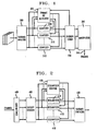
- FIGs. 1 and 2 present a first illustrative embodiment of the present invention comprising digital image coder and decoder, respectively.
- FIG. 3 shows a typical subband filter arrangement in accordance with one aspect of the present invention.
- FIGs. 4 and 5 present a second illustrative embodiment of the present invention comprising digital image coder and decoder, respectively.
- FIG. 6 presents subbands arranged in order of perceived visibility of errors.
- FIG. 7 presents a graph illustrating bit allocation as carried out by a bit allocation block.
- FIG. 8 presents a third illustrative embodiment of the present invention comprising an image coder.
- FIG. 9 presents a graphical representation of the subbands including an indication of an illustrative high energy region and a mapping thereof among the subbands.
- FIG. 10 presents a flowchart of a procedure for determining quantizer parameters.
- FIGs. 1 and 2 present a first illustrative embodiment of the present invention.
- FIG. 1 shows an image encoder which employs the adaptive bit allocation of the present invention together with conditional replenishment and quantization based on PCM with a uniform quantizer or Geometric Vector Quantization.
- FIG. 2 shows an image decoder based on the same inventive techniques.
- FIG. 1 shows a representation of a graphical image, e.g., sequential frames of a video image. Since the subband filtering used in this illustrative image coding application uses 2 taps for the temporal filtering, it proves convenient to store two successive fames of the input signal in block 300. As a specific example, each fame of the image contains 240x360 pixels which is known as the Common Intermediate Format (CIF). For present purposes, the image will be considered to be a multi-level image having up to 256 possible intensity levels. Color images are amenable to coding using the present inventive techniques.
- CIF Common Intermediate Format
- the spatio-temporal frequency components of the image are generated using 2-tap Haar filters for the temporal filtering and 10-tap one-dimensional quadrature mirror filters (QMFs), of the type described in J. D. Johnston, A Filter Family Designed for Use in Quadrature Mirror Filter Banks , Proceedings ICASSP (1980), for the spatial filtering.
- QMFs quadrature mirror filters
- the subband framework consists of 11 spatio--temporal frequency bands, as shown in FIG 3. Except for the particular choice of subband filters, this is the same basic structure as used in G. Karlsson and M.
- HP and LP refer to high--pass filtering and low--pass filtering respectively while the subscripts t,h, and v refer to temporal, horizontal and vertical filtering respectively.
- the subbands whose signal energy content is typically low are discarded without causing severe degradation in the reconstructed image sequence.
- the remaining subbands are encoded using conditional replenishment to take advantage of the temporal correlation and either PCM with a uniform quantizer (such as that described by Jayant and Noll, Digital Coding of Waveforms: Principles and Applications to Speech and Video (1984)), or Geometric Vector Quantization, (such as that described in the patent application incorporated by reference).
- the highest spatio-temporal frequency subbands are discarded due to their general perceptual insignificance.
- the subbands labeled 9 through 11 in FIG. 3 are discarded without causing severe image quality distortion.
- any number of high frequency subbands may be discarded.
- the significant subbands are encoded using either a scalar quantizer or Geometric Vector Quantization shown as blocks 310i in FIG. 1.
- the dynamic bit allocation is represented by block 320 in FIG 1.
- the bit allocation depends on the amount of conditional replenishment and the amount of motion data as determined by the signal energy in the appropriate subband.
- Conditional replenishment is applied to all of the significant subbands and is part of dynamic bit allocation block 320.
- Conditional replenishment is performed on a pixel basis in the subbands using a scalar quantizer, and on a block basis in the subbands using Geometric Vector Quantization.
- the block size corresponds to the block size used in the vector quantization scheme under consideration.
- Conditional replenishment on a pixel basis is described by the following expression: where x (i,j,t) is the original pixel value in the ith row, jth column and time t, and x ⁇ (i,j,t) is the quantized pixel value in the ith row, jth column and time t.
- T cr is an empirically derived conditional replenishment scalar threshold.
- the choice for T cr determines how much of the subband data will be repeated from the previously encoded subbands. As an example for some typical video sequences, we have found a good choice for T cr to be between 10 and 25.
- Performing conditional replenishment on a block basis is similar to the pixel--based approach except that the condition in Eq. (1) must hold for all the pixels in a block of data; otherwise the block must be quantized and transmitted.
- the side information indicating which pixels are repeated from the previous fame and which pixels are quantized is sent to block 330, the entropy coder, to be encoded.
- the entropy coder may be any lossless coding technique and for this example is the adaptive Lempel-Ziv algorithm. See, e.g., T. A Welch, A Technique for High Performance Data Compression , IEEE Computer (1988).
- the number of bits that the entropy coder of block 330 in FIG. 1 needs to encode the conditional replenishment side--information is fed to the Dynamic Bit Allocation block 320 to update the number of bits available to encode the subband data.
- the image signal is then multiplexed onto communication channel 345 for transmission to a decoder ( see discussion below).
- the dynamic bit allocation technique has two significant parts.
- the first part is the ordering of the subbands based on their perceptual significance.
- the lowest spatio-temporal frequency band is treated as the most significant in that it contains the most signal energy and most of the original image structure. This band is very accurately encoded.
- the next most significant subband is the motion subband (corresponding to subband 8 in FIG. 3). This subband is given enough bits to encode the motion information.
- the remaining bits are used to encode the high spatial--low temporal frequency subbands (corresponding to subbands 2--7 in FIG. 3).
- the high motion activity should mask the loss in high spatial details. When the motion activity drops, more bits are left to encode the high spatial details which now become visible.
- the second part of the dynamic bit allocation is to locate the significant areas of the image to encode. This is done across all the subbands by choosing the blocks with the highest average energy to encode.
- the present embodiment first encodes the lowest spatio-temporal frequency band using PCM and a uniform quantizer.
- the uniform quantizer consists of 6 -- 8 bits. If the signal in the lowest frequency subband contains data which possesses a probability density function that is not uniform, PCM is applied with a quantizer that suits the probability density function of the signal. Applying a quantizer suited to a signal's probability density function is a conventional technique and is described, e.g. , in the above-cited Jayant and Noll reference.
- the number of bits needed to encode the lowest spatio--temporal frequency band using PCM and a uniform quantizer is fed into block 320 -- Dynamic Bit Allocation -- to update the number of bits available to encode the high spatio--temporal frequency bands.
- the next band that is encoded corresponds to the subband containing high temporal frequency components and low spatial frequency components.
- this corresponds to subband 8.
- This frequency subband contains much of the motion information of the video signal.
- the signal energy in this subband gives a good indication of the amount of motion in the video sequence at any given time.
- Subband 8 is encoded by quantizing the data in the blocks whose local energy exceeds a predetermined threshold value as given by: where the summation is performed over the block of data, N denoter the block size and T m is a predetermined scalar motion threshold value. For this example, a good value for T m is 100.
- the blocks in the motion subband whose average energy exceeds the threshold T m are encoded using Geometric Vector Quantization with either 2 or 3 levels (described in the above-referenced U.S. Patent Application Serial No. 07/503,659).
- the amount of bits that are required to encode the motion data accurately is fed back to block 320 -- Dynamic Bit allocation -- to update the number of bits left to encode the remaining subbands.
- the subbands which are encoded last correspond to the low temporal frequency components and high spatial frequency components. For the example framework illustrated in FIG. 3, this corresponds to the subbands labeled 2 through 7.
- the bits which are left to encode subbands 2--7 are distributed to the blocks across all the remaining subbands with the largest local energy as defined in Eq. 2.
- the blocks may be encoded using Geometric Vector Quantization. Any of these remaining blocks, especially those corresponding to lower spatial frequencies (such as subbands 2--4 in FIG.3), may be encoded using the scalar quantizer described for the lowest spatio--temporal frequency band. In this case, the pixels with the largest absolute value are encoded.
- FIG. 2 shows a decoder counterpart to the coder in FIG. 1.
- Coded signals received from the channel are first demultiplexed in unit 400. Side information is used by the dequantizer control unit 420 to determine which areas of the subbands have been repeated from the previously encoded subband as given by conditional replenishment, which areas have been quantized, and which areas have been zeroed out
- the dequantizer units labeled 410i reconstruct the data from the vector indices and magnitude information as provided by the Geometric Vector Quantizer.
- the subband synthesis unit 430 performs the operations of the subband analysis unit 300 in reverse to reconstruct the images.
- the above embodiment can be adapted to other frameworks besides the one illustrated in FIG. 3 allowing for a greater control over which subbands are perceptually most significant and which areas of the image are perceptually most significant.
- a second illustrative embodiment of the present invention codes video frame sequences at a maximum constrained bit rate. This embodiment provides coded video to be transmitted or stored on a medium with a specified constant or time varying bit rate.
- FIG. 4 presents an embodiment of the video coder according to the present invention.
- An input video image sequence is decomposed into temporal and spatial subbands by the subband analysis filter block 300.
- the subband structure is the same as that shown in FIG. 4 of the above-referenced patent application serial number 07/503,659.
- the outputs of the subband filters are critically sampled, and bands 7, 9, 10, and 11 are set to zero.
- the decomposed video sequence therefore, contains half the number of samples as the original input image sequence.
- the zeroed bands typically contain very low energy, therefore, zeroing these bands introduces very little degradation in the reconstructed video sequence.
- Two-tap temporal filters are used to minimize delay, and tenth-order quadrature mirror filters are used for the spatial decomposition.
- the decomposition by filter block 300 produces subbands with reduced spatial redundancy. However, temporal redundancy within the lower temporal subbands and spatial correlations between the subbands remain.
- the technique of conditional replenishment is used to remove temporal redundancy from the coded signal, thereby achieving higher decoded video quality at a specified coding rate.
- Subband correlation may be taken advantage of by dequantizer blocks 610i and dequantizer control block 620 to further improve the quality of the decoded video.
- this embodiment allocates coding bits within and among the subbands to minimize the perceived coding distortion. Quantization errors are most noticeable in subband 1 because it contains most of the basic image structure, and in band 8 for moving areas of the video sequence.
- FIG. 7 presents a graph illustrating bit allocation as carried out by block 520. Each node of the graph corresponds to one of the subbands, and each edge is labeled with the proportion of bits remaining from the preceding subband which are allocated to the lower subband node.
- bits remaining after quantizing bands 1 and 8 are allocated equally to subbands 2, 3, 5, and 6. Although equal bandwidth is allocated to the lower priority bands, 5 and 6, fewer bits per sample are allocated to these bands since they contain more samples.
- the advantage in allocating bits in this fashion is that the quantizers for bands 1 and 8, and the quantizers for bands 2, 3, 5, and 6 can be implemented in parallel, yielding greater efficiency in operation.
- Temporal redundancy in bands 1, 2, 3, 4, 5, and 6 is removed by selectively repeating subband samples which differ by less than a determined threshold from the corresponding previously transmitted value.
- This technique is referred to as conditional replenishment, and has been described above with reference to the first illustrative embodiment.
- Conditional replenishment is applied in the subband analysis framework. An advantage is obtained by allocating bandwidth for replenishment on a priority basis to those subbands which have the highest visibility. This results in a perceptually improved decoded quality.
- Each quantizer block 510i includes a memory which contains the previously quantized subband samples. Since the samples are represented with a linear eight-bit code, the error magnitude is in the range (0, 256). A histogram of the occurrence of the error values is efficiently generated by the quantizer 310i using the error value, for each sample in the subband, as an address into one of 256 memory locations which are incremented for each occurrence of the corresponding error value.
- a coding error threshold is determined from the histogram by summing the number of occurrences for each error value, starting with the largest error and proceeding towards the lowest error, until the bandwidth needed to quantize the number of samples indicated by that sum equals the coding bandwidth available.
- the address of the location being accessed when the summation is terminated is equal to the coding error threshold
- the threshold is limited to be greater than an error which is not visible in the decoded video sequence. This minimum value has been empirically determined to be three (3) for subbands 1, 2, and 3. Samples which have an error greater than the determined threshold are coded and transmitted to the decoder as described below.
- the locations of samples which are below the threshold are efficiently coded using run-length coding, and entropy coding, e.g. , Huffman coding, of the run-lengths, implemented by entropy coder 530. Excess bits are available to be allocated to lower priority subbands when the error threshold determined by the histogram method falls below the minimum visibility threshold.
- Sample values which are transmitted in bands 1, 2, 3, and 4 are coded using a scalar quantizer.
- Sample values which are transmitted in bands 5 and 6 are coded using a scalar or vector quantizer, and in particular the geometric vector quantizer described in the above-referenced and incorporated patent applications.
- the determination to use the scalar or vector quantizer is made by applying a threshold to the bandwidth allocated to subbands 5 and 6. An allocation below an empirically determined threshold indicates a high degree of motion in the video sequence. It has been empirically determined that perceived distortion is minimized when the vector quantizer is used for a bandwidth allocation falling below 60 percent of the maximum allocation. An advantage is achieved by this method because the distortion introduced by the vector quantizer is masked by motion in the video sequence.
- the scalar quantizer is used to reduce the errors introduced by the vector quantizer.
- This section describes an efficient implementation of the geometric vector quantizer used in subbands 5, 6, and 8. This implementation provides a means for constraining the bandwidth necessary to code the given subband, and provides an efficient technique to search for null vectors.
- Null vectors correspond to repeated samples in bands 5 and 6, and refer to zero valued samples in band 8.
- the geometric vector codebook described in patent application serial number 07/503,659 requires approximately equal complexity to identify both null and non-null vectors. Because the majority of subband samples typically are coded as the null vector, a significant reduction in vector search complexity may be achieved by an efficient null vector search technique. Null vectors may be identified by first determining the sample in each vector having the greatest magnitude, for band 8, or the greatest magnitude difference, for bands 5 and 6, where conditional replenishment is used. A coding threshold is determined by the histogram method described above, using the maximum magnitudes, for band 8, or maximum difference magnitudes, for bands 5 and 6.
- null vectors Those vectors having a maximum magnitude falling below the coding threshold are identified as null vectors.
- the remaining vectors are coded using the efficient codebook search techniques described in the above referenced and incorporated patent applications.
- the location of null vectors is coded using run-length coding and entropy coding, e.g. , Huffman coding, of the run-lengths.
- the coding threshold in band 8 is limited to a minimum value of 6. If the coding value is determined to be less than 6 by the histogram method,, excess coding bandwidth is available to allocate to the lower priority bands.
- the transmitted sample values are written into the corresponding locations in each subband sample memory in the quantizer blocks 510i.
- the channel multiplexer block 340 formats the information from the quantizer blocks 510i so that it can be transmitted or stored on the appropriate medium This information includes the run-length encoded repeated sample locations and the transmitted quantized samples. Side information is provided for bands 5 and 6 to specify whether scalar or vector quantization was used in the encoding process.
- FIG. 5 presents an embodiment of the decoder according to the present invention.
- the channel demultiplexer block 400 operates in reciprocal fashion to multiplexer 340 in FIG. 4 to separate the coded subband information. This information is provided to the dequantizer blocks 610i for each subband. For the case of vector quantization in bands 5, 6, and 8, the dequantizers reconstruct the vector samples as described in U.S. patent application serial number 07/503,659. The remaining samples in band 8 are set to zero.
- the dequantizer blocks 610i, corresponding to subbands 1, 2, 3, 4, 5, and 6, include memories containing the previously dequantized subband samples. Samples which are quantized and transmitted by the encoder replace the corresponding samples in these subband memories; the remaining samples are repeated. The difference between the transmitted samples and previously stored samples, for subband 1, are calculated and stored for use as described below.
- the selective modification of the subband samples in the decoder improves the perceived quality of the reconstructed video signal.
- Objectionable errors in the decoded video sequence may occur when the coding rate is constrained such that there is insufficient bandwidth to transmit all of the subband samples with errors above a perceptible threshold.
- the decoder subbands using conditional replenishment contain three types of samples: ( i ) low error samples which are repeated, ( ii ) newly received samples, and ( iii ) large error samples which cause objectionable artifacts in the decoded video sequence. These large errors occur most frequently in the subbands with lower bandwidth allocation priority. The errors typically appear as edges which remain behind moving objects.
- Quantization errors in subband 1 remain small since it has the highest bandwidth allocation priority. This fact, along with the spatial correlation between the subbands, is used to identify samples in the upper subbands which have a large error.
- the technique compares the band 1 difference signal, described above, to an empirically determined threshold. A useful threshold value is 12 for the range of intensity values in band 1 is (0, 256). If the difference is greater than the threshold, the corresponding spatial samples in subbands 2, 3, 4, 5, and 6 are tested further.
- Each sample in subband 1 corresponds to four samples in subbands 5 and 6 since subband 1 is decimated by an additional factor of two in the analysis filters 300. If the corresponding upper subband samples have not been transmitted by the encoder, they are assumed to have large error and are processed further to reduce the resultant distortion.
- a useful technique is to set these samples to zero in order to eliminate trailing edges on moving areas. Other techniques, such as interpolating these samples between low error samples, may prove advantageous in smooth areas of the image. This technique provides an advantage by reducing perceived coding distortion without transmitting additional side information to the decoder.
- the resulting subband samples are finally applied to the subband synthesis block 430, which reconstructs the sequence of video frames.
- the overall structure of the encoder of this embodiment is presented in FIG. 8.
- a series of video frames are fed into a sub-band analysis filterbank 300 which divides the frequency spectrum into sub-bands.
- the output of the sub-band analysis is used by a dynamic bit allocator 720.
- the dynamic bit allocator 720 is responsible for deciding how much of the total available bit rate should be allocated to each sub-band.
- the dynamic bit allocator 720 also determines which spatial regions are more important to code within each sub-band This information, along with the output of the sub-band analysis 300, is provided to the quantizers 710i. Under certain circumstances, feedback from the entropy coder 330 may be needed to determine the exact bit rate required to code some of the sub-bands.
- the resulting bit stream is multiplexed 340 and transmitted over a channel 345.
- the dynamic bit allocator 720 assumes that there is a fixed rate available as each frame enters the system, although that rate could change when the next frame enter
- a coding advantage can be achieved by dividing the sub-bands into regions and allocating more bits to regions that are deemed to be perceptually more relevant.
- the definition of perceptual relevance may vary for different applications.
- a convenient method for determining perceptually relevant regions is to divide the high-pass temporal, low-pass spatial sub-band (sub-band 8 in FIG. 9) into blocks and to compute the energy in each block using, where x i,j,t represents the intensity value of a pixel at column i, row j, at time instant t.
- the computed energy values for each block, e k,l,t are sorted in decreasing order and classified into two or more groups. Illustratively, two classes of blocks are assumed, high energy and low energy.
- the output from the sub-band analysis filterbank 300 is provided to the dynamic bit allocator 720.
- the dynamic bit allocator 720 is responsible for determining the energy grouping.
- this spatial information is used to quantize all of the sub-bands to be coded (FIG. 9). For example, if a block were classified as a high energy block, then the corresponding block could be quantized using a finer quantizer in each of the coded subbands. By preserving higher quality in that block in all of the coded sub-bands, the reconstructed image will have a higher SNR in the corresponding block. This is ideal for an application which requires more spatial detail in moving regions. Such an application might be, e.g. , the coding of an image sequence of a person using the American Sign Language (used commonly by deaf people). On the other hand, fewer bits could be allocated to these regions for applications where spatial detail is not needed where motion occurs. There may be any number of high and low energy blocks identified in sub-band 8.
- motion activity When motion activity is low, sub-band images are not segregated into high and low motion regions. In this case, all the regions of the sub-band image are treated as being equally important.
- the motion activity is determined by keeping a history of the extrema of total energy in band 8. Illustratively, if the total energy of sub-band 8 for a current frame is within the bottom one-third of the dynamic range of the total energy history of the sub-band, motion activity is considered to be low.
- an initial allotment of bits is determined to code each sub-band-
- a typical initial allotment provides 50% of the total bits to sub-band 1, another 40% to sub-band 8, and the remaining 10% is divided among sub-bands 2-7.
- the total number of bits is determined by the channel bandwidth and the fame rate.
- the embodiment codes sub-band 1 first since sub-band 1 contains a significant portion of the energy in the original signal. Given the initial allotment of bits to code this sub-band, the number of pixels which can be accurately coded is computed by dividing the total number of bits allotted to the sub-band by the number of bits it takes to code each pixel. The number of bits needed to code each pixel is the sum of the bits needed to represent the address, sign, and magnitude of the transmitted pixel. The number of address and sign bits remain fixed within a subband, but the number of bits needed for representing pixel magnitude is determined using an iterative procedure ( see FIG. 10).
- This procedure begins by computing a histogram of the absolute values of the difference between like-address pixels in the current and previous frames. The maximum value is retained. The histogram is used to determine the threshold value of a dead-zone quantizer.
- a dead-zone quantizer automatically eliminates coding pixel values which fall below a threshold. Sub-band difference values that are greater than the dead-zone threshold get coded, while those at or below the threshold are not coded but are repeated from the previous frame.
- the system uses an empirically derived minimum threshold value as an initial estimate of the actual dead-zone threshold. For a channel bit-rate of 384 kbs, illustrative minimum threshold estimates for bands 1-8 are: 3, 4, 4, 5, 5, 5, 5, 5, and 5.
- the step size for the quantizer is then set to be twice the value of the dead-zone threshold.
- the maximum amount of distortion that can be introduced by a single uncoded pixel (which falls at or below the threshold) is the threshold value. Since this level of distortion is assumed to be acceptable for pixels which are not coded, the same maximum distortion is allowed on quantized pixels which are coded by setting the step size to twice the dead-zone threshold.
- the minimum threshold value is based on experiments which were performed to identify the amount of distortion that can be introduced into each subband before the noise becomes noticeable. The reason a minimum threshold is introduced is to prevent any particular sub-band from being overcoded.
- num_levels (max_val-threshold) step_size
- the number of bits needed to code a pixel can be evaluated by adding the number of bits needed for the address and sign to the number of bits needed for this quantizer. Dividing the total number of bits by the bits per pixel determines the number of pixels that can be coded within that sub-band region. A count of the number of pixels which fall above the dead-zone threshold is computed from the histogram. If this count is less than the allowed count, then the quantizer parameters are fixed. If, however, the count is larger than the allowed count, then the dead-zone threshold is incremented and the computations are repeated as shown in FIG. 10.
- the dead-zone threshold forces the step-size to increase since it is set to twice the dead-zone threshold. This, in turn, eventually reduces the number of bits required to quantize the same data, albeit more coarsely.
- the dead-zone value is incremented until the count of pixels to be coded falls below the number of coded pixels allowed. When this occurs, the quantizer parameters are fixed and provided to the quantizer 710i.
- the quantizer parameters are then used to actually code the sub-band. There may be some bits leftover after coding sub-band 1 if the number of pixels to be coded is less than the number of pixels allowed This can happen in two circumstances. First, if the minimum dead-zone threshold is used to prevent overcoding, then the actual count will usually be less than the allowed count. Second, since the histogram uses discrete values, the desired count may not match up exactly with the allowed count. To prevent the system from using more than its allocated bit rate, the value of the dead-zone threshold is incremented uni the actual count is less than or equal to the allowed count. Under these two circumstances, any leftover bits are immediately re-allocated to the next sub-band to be coded.
- sub-band 8 is coded next.
- the exact same procedure is followed for sub-band 8 as was used for sub-band 1, except that the original fame is used rather than the difference between two frames. This method was chosen because of the low correlation between successive frames in sub-band 8. Once again, any leftover bits are passed on to help code subsequent sub-bands.
- each of the remaining low-pass temporal sub-bands (sub-bands 2-7) are coded.
- Two alternative methods for doing this are provided.
- the first method concerns processing the sub-bands in a perceptually significant order. 2, 3, 5, 6, 4, 7. As with sub-band 8, any bits leftover from previous coding are added to the predetermined bit allocation for the current sub-band.
- the dead-zone quantizer on the difference signal is used to update these sub-bands.
- an empirically derived minimum dead-zone threshold is imposed when coding these sub-bands.
- the second method uses an energy criterion which selects the highest values from the difference signal from all of the sub-bands 2-7 rather than looking at each of bands 2-7 individually.
- sub-band 8 Of the high-pass temporal sub-bands, only sub-band 8 is coded. Subbands 9, 10, and 11 are all set to zero and are not coded (as discussed above, this may be done by filterbank 300).
- This embodiment employs the decoder discussed in section B.3, above , and presented in FIG. 5.
Abstract
Description
- This invention relates to the efficient digital coding of multi-valued signals, and more particularly, to the digital coding of video signals at low rates where the rate is fixed for each video frame.
- Good quality, low bit rate video coding is required for such applications as teleconferencing over existing and future networks, as well as CD-ROM storage. An effective low rate coder should remove the redundancies due to temporal and spatial correlations along with perceptually irrelevant components of an image sequence.
- Subband digital coding techniques are well known in the art. See, e.g., N. S. Jayant and P. Noll, Digital Coding of Waveforms: Principles and Applications to Speech and Video (1984).
- Subband coding techniques have been used for image coding in a three-dimensional spatio-temporal subband framework as described in G. Karlsson and M. Vetterli, Three Dimensional Subband Coding of Video, Proceedings ICASSP (1988), 1100-1103. The technique described there employs multidimensional filtering to generate spatio-temporal frequency bands or subbands using so called quadrature mirror filters. These latter filters are described, e.g., in J. D. Johnston, A Filter Family Designed for Use in Quadrature Mirror Filter Bands, Proceedings ICASSP (1980).
- The present invention takes advantage of the three-dimensional subband framework in determining a dynamic bit allocation that relies on perceptual criteria of the human visual system. This is done in terms of both the relative significance of individual subbands, and the significance of local spatial areas within such subbands. Three illustrative embodiments of the present invention are described below.
- For example, in the first illustrative embodiment of the present invention, an image sequence is separated in different spatio-temporal frequency bands. The temporal correlations are exploited by using conditional replenishment on the subband data between frames. Unless the subband is discarded due to perceptually insignificant information as measured by the low signal energy content in the subband, conditional replenishment is applied to the data either on a pixel or block basis. The subband corresponding to the lowest spatio-temporal frequency components needs to be encoded accurately due to the high signal energy present in the subband and its perceptual significance for video data. The lowest spatiotemporal frequency band is quantized using PCM with a uniform quantizer.
- The perceptually significant upper subbands as measured by their overall signal energy are encoded either by Geometric Vector Quantization (described in commonly assigned U.S. Patent Application Serial No. 07/503,659, entitled "Geometric Vector Quantization", filed April 3, 1990, and in commonly assigned U.S. Patent Application Serial No. 07/832,536, entitled "Geometric Vector Quantization", filed on even date herewith, which are hereby incorporated by reference as if fully set forth herein) or by conventional PCM using a uniform quantizer.
- The areas of the significant upper frequency subbands which are to be encoded are chosen by using the adaptive bit allocation scheme of the present invention.
- FIGs. 1 and 2 present a first illustrative embodiment of the present invention comprising digital image coder and decoder, respectively.
- FIG. 3 shows a typical subband filter arrangement in accordance with one aspect of the present invention.
- FIGs. 4 and 5 present a second illustrative embodiment of the present invention comprising digital image coder and decoder, respectively.
- FIG. 6 presents subbands arranged in order of perceived visibility of errors.
- FIG. 7 presents a graph illustrating bit allocation as carried out by a bit allocation block.
- FIG. 8 presents a third illustrative embodiment of the present invention comprising an image coder.
- FIG. 9 presents a graphical representation of the subbands including an indication of an illustrative high energy region and a mapping thereof among the subbands.
- FIG. 10 presents a flowchart of a procedure for determining quantizer parameters.
- FIGs. 1 and 2 present a first illustrative embodiment of the present invention.
- FIG. 1 shows an image encoder which employs the adaptive bit allocation of the present invention together with conditional replenishment and quantization based on PCM with a uniform quantizer or Geometric Vector Quantization. Similarly, FIG. 2 shows an image decoder based on the same inventive techniques. Each of the system elements will now be described individually.
- FIG. 1 shows a representation of a graphical image, e.g., sequential frames of a video image. Since the subband filtering used in this illustrative image coding application uses 2 taps for the temporal filtering, it proves convenient to store two successive fames of the input signal in
block 300. As a specific example, each fame of the image contains 240x360 pixels which is known as the Common Intermediate Format (CIF). For present purposes, the image will be considered to be a multi-level image having up to 256 possible intensity levels. Color images are amenable to coding using the present inventive techniques. - Referring to FIG. 1, successive fames of a video image are applied to the subband analysis filter block 300 (presented in greater detail in FIG 3). There, the spatio-temporal frequency components of the image are generated using 2-tap Haar filters for the temporal filtering and 10-tap one-dimensional quadrature mirror filters (QMFs), of the type described in J. D. Johnston, A Filter Family Designed for Use in Quadrature Mirror Filter Banks, Proceedings ICASSP (1980), for the spatial filtering. In a typical embodiment of the present invention, the subband framework consists of 11 spatio--temporal frequency bands, as shown in FIG 3. Except for the particular choice of subband filters, this is the same basic structure as used in G. Karlsson and M. Vetterli, Three-Dimensional Subband Coding of Video, Proceedings ICASSP (1988). The terms HP and LP refer to high--pass filtering and low--pass filtering respectively while the subscripts t,h, and v refer to temporal, horizontal and vertical filtering respectively. The subbands whose signal energy content is typically low are discarded without causing severe degradation in the reconstructed image sequence. The remaining subbands are encoded using conditional replenishment to take advantage of the temporal correlation and either PCM with a uniform quantizer (such as that described by Jayant and Noll, Digital Coding of Waveforms: Principles and Applications to Speech and Video (1984)), or Geometric Vector Quantization, (such as that described in the patent application incorporated by reference).
- The highest spatio-temporal frequency subbands are discarded due to their general perceptual insignificance. For the particular scheme described here, the subbands labeled 9 through 11 in FIG. 3 are discarded without causing severe image quality distortion. In general, depending on the bit rate, quality sought, and subband framework, any number of high frequency subbands may be discarded.
- The significant subbands are encoded using either a scalar quantizer or Geometric Vector Quantization shown as
blocks 310i in FIG. 1. - The dynamic bit allocation is represented by
block 320 in FIG 1. The bit allocation depends on the amount of conditional replenishment and the amount of motion data as determined by the signal energy in the appropriate subband. - Conditional replenishment is applied to all of the significant subbands and is part of dynamic
bit allocation block 320. Conditional replenishment is performed on a pixel basis in the subbands using a scalar quantizer, and on a block basis in the subbands using Geometric Vector Quantization. The block size corresponds to the block size used in the vector quantization scheme under consideration. Conditional replenishment on a pixel basis is described by the following expression:
where x (i,j,t) is the original pixel value in the ith row, jth column and time t, and x̂(i,j,t) is the quantized pixel value in the ith row, jth column and time t. Q· represents quantization of the term in the bracket while Tcr is an empirically derived conditional replenishment scalar threshold. The choice for Tcr determines how much of the subband data will be repeated from the previously encoded subbands. As an example for some typical video sequences, we have found a good choice for Tcr to be between 10 and 25. Performing conditional replenishment on a block basis is similar to the pixel--based approach except that the condition in Eq. (1) must hold for all the pixels in a block of data; otherwise the block must be quantized and transmitted. - After conditional replenishment is performed on the subbands with significant information, the side information indicating which pixels are repeated from the previous fame and which pixels are quantized is sent to block 330, the entropy coder, to be encoded. The entropy coder may be any lossless coding technique and for this example is the adaptive Lempel-Ziv algorithm. See, e.g., T. A Welch, A Technique for High Performance Data Compression, IEEE Computer (1988). The number of bits that the entropy coder of
block 330 in FIG. 1 needs to encode the conditional replenishment side--information is fed to the DynamicBit Allocation block 320 to update the number of bits available to encode the subband data. After entropy coding, the image signal is then multiplexed ontocommunication channel 345 for transmission to a decoder (see discussion below). - The dynamic bit allocation technique has two significant parts. The first part is the ordering of the subbands based on their perceptual significance. In this regard, the lowest spatio-temporal frequency band is treated as the most significant in that it contains the most signal energy and most of the original image structure. This band is very accurately encoded. The next most significant subband is the motion subband (corresponding to
subband 8 in FIG. 3). This subband is given enough bits to encode the motion information. The remaining bits are used to encode the high spatial--low temporal frequency subbands (corresponding to subbands 2--7 in FIG. 3). When the motion information is high, more bits are given to the motion subband and fewer are left to encode the high spatial details. The high motion activity should mask the loss in high spatial details. When the motion activity drops, more bits are left to encode the high spatial details which now become visible. - The second part of the dynamic bit allocation is to locate the significant areas of the image to encode. This is done across all the subbands by choosing the blocks with the highest average energy to encode.
- Because the lowest spatio-temporal frequency subband (subband 1) includes much of the basic image structure and most of the signal energy, it is important to accurately encode this subband. Therefore the present embodiment first encodes the lowest spatio-temporal frequency band using PCM and a uniform quantizer. For a typical image scheme, the uniform quantizer consists of 6 -- 8 bits. If the signal in the lowest frequency subband contains data which possesses a probability density function that is not uniform, PCM is applied with a quantizer that suits the probability density function of the signal. Applying a quantizer suited to a signal's probability density function is a conventional technique and is described, e.g., in the above-cited Jayant and Noll reference. The number of bits needed to encode the lowest spatio--temporal frequency band using PCM and a uniform quantizer is fed into
block 320 -- Dynamic Bit Allocation -- to update the number of bits available to encode the high spatio--temporal frequency bands. - The next band that is encoded corresponds to the subband containing high temporal frequency components and low spatial frequency components. For the example presented in the framework illustrated in FIG. 3, this corresponds to
subband 8. This frequency subband contains much of the motion information of the video signal. The signal energy in this subband gives a good indication of the amount of motion in the video sequence at any given time.Subband 8 is encoded by quantizing the data in the blocks whose local energy exceeds a predetermined threshold value as given by:
where the summation is performed over the block of data, N denoter the block size and Tm is a predetermined scalar motion threshold value. For this example, a good value for Tm is 100. The blocks in the motion subband whose average energy exceeds the threshold Tm are encoded using Geometric Vector Quantization with either 2 or 3 levels (described in the above-referenced U.S. Patent Application Serial No. 07/503,659). The amount of bits that are required to encode the motion data accurately is fed back to block 320 -- Dynamic Bit allocation -- to update the number of bits left to encode the remaining subbands. - The subbands which are encoded last, correspond to the low temporal frequency components and high spatial frequency components. For the example framework illustrated in FIG. 3, this corresponds to the subbands labeled 2 through 7. The bits which are left to encode
subbands 2--7 are distributed to the blocks across all the remaining subbands with the largest local energy as defined in Eq. 2. The blocks may be encoded using Geometric Vector Quantization. Any of these remaining blocks, especially those corresponding to lower spatial frequencies (such assubbands 2--4 in FIG.3), may be encoded using the scalar quantizer described for the lowest spatio--temporal frequency band. In this case, the pixels with the largest absolute value are encoded. - FIG. 2 shows a decoder counterpart to the coder in FIG. 1. Coded signals received from the channel are first demultiplexed in
unit 400. Side information is used by thedequantizer control unit 420 to determine which areas of the subbands have been repeated from the previously encoded subband as given by conditional replenishment, which areas have been quantized, and which areas have been zeroed out The dequantizer units labeled 410i reconstruct the data from the vector indices and magnitude information as provided by the Geometric Vector Quantizer. Thesubband synthesis unit 430 performs the operations of thesubband analysis unit 300 in reverse to reconstruct the images. - The above embodiment can be adapted to other frameworks besides the one illustrated in FIG. 3 allowing for a greater control over which subbands are perceptually most significant and which areas of the image are perceptually most significant.
- A second illustrative embodiment of the present invention codes video frame sequences at a maximum constrained bit rate. This embodiment provides coded video to be transmitted or stored on a medium with a specified constant or time varying bit rate.
- FIG. 4 presents an embodiment of the video coder according to the present invention. An input video image sequence is decomposed into temporal and spatial subbands by the subband
analysis filter block 300. The subband structure is the same as that shown in FIG. 4 of the above-referenced patent application serial number 07/503,659. The outputs of the subband filters are critically sampled, andbands - The decomposition by
filter block 300 produces subbands with reduced spatial redundancy. However, temporal redundancy within the lower temporal subbands and spatial correlations between the subbands remain. The technique of conditional replenishment is used to remove temporal redundancy from the coded signal, thereby achieving higher decoded video quality at a specified coding rate. Subband correlation may be taken advantage of bydequantizer blocks 610i and dequantizer control block 620 to further improve the quality of the decoded video. - During peak motion of objects in a video signal, the available coding rate may be insufficient to code all of the perceptually significant subband samples. Therefore, this embodiment allocates coding bits within and among the subbands to minimize the perceived coding distortion. Quantization errors are most noticeable in
subband 1 because it contains most of the basic image structure, and inband 8 for moving areas of the video sequence. - Samples in
bands Band 4 usually has very low energy, therefore it is perceptually less significant thanbands - This ordering is used to determine the priority of allocating available bandwidth to each subband quantizer
block 310i. Bandwidth or bit allocation is implemented by dynamicbit allocation block 520. Because the bandwidth required to code different bands is correlated, a fixed proportion of the remaining bandwidth may be allocated to the subbands at each stage of allocation. These proportions have been determined empirically. FIG. 7 presents a graph illustrating bit allocation as carried out byblock 520. Each node of the graph corresponds to one of the subbands, and each edge is labeled with the proportion of bits remaining from the preceding subband which are allocated to the lower subband node. - The bits remaining after quantizing
bands bands bands - Temporal redundancy in
bands - In order to determine which subband samples should be repeated,, the magnitude difference between the subband samples being quantized and the corresponding samples of a previously quantized video frame is calculated Each
quantizer block 510i includes a memory which contains the previously quantized subband samples. Since the samples are represented with a linear eight-bit code, the error magnitude is in the range (0, 256). A histogram of the occurrence of the error values is efficiently generated by thequantizer 310i using the error value, for each sample in the subband, as an address into one of 256 memory locations which are incremented for each occurrence of the corresponding error value. A coding error threshold is determined from the histogram by summing the number of occurrences for each error value, starting with the largest error and proceeding towards the lowest error, until the bandwidth needed to quantize the number of samples indicated by that sum equals the coding bandwidth available. The address of the location being accessed when the summation is terminated is equal to the coding error threshold The threshold is limited to be greater than an error which is not visible in the decoded video sequence. This minimum value has been empirically determined to be three (3) forsubbands entropy coder 530. Excess bits are available to be allocated to lower priority subbands when the error threshold determined by the histogram method falls below the minimum visibility threshold. - Sample values which are transmitted in
bands bands subbands - This section describes an efficient implementation of the geometric vector quantizer used in
subbands - Null vectors correspond to repeated samples in
bands band 8. The geometric vector codebook described in patent application serial number 07/503,659 requires approximately equal complexity to identify both null and non-null vectors. Because the majority of subband samples typically are coded as the null vector, a significant reduction in vector search complexity may be achieved by an efficient null vector search technique. Null vectors may be identified by first determining the sample in each vector having the greatest magnitude, forband 8, or the greatest magnitude difference, forbands band 8, or maximum difference magnitudes, forbands band 8 is limited to a minimum value of 6. If the coding value is determined to be less than 6 by the histogram method,, excess coding bandwidth is available to allocate to the lower priority bands. - The transmitted sample values are written into the corresponding locations in each subband sample memory in the quantizer blocks 510i. The
channel multiplexer block 340 formats the information from the quantizer blocks 510i so that it can be transmitted or stored on the appropriate medium This information includes the run-length encoded repeated sample locations and the transmitted quantized samples. Side information is provided forbands - FIG. 5 presents an embodiment of the decoder according to the present invention. The
channel demultiplexer block 400 operates in reciprocal fashion tomultiplexer 340 in FIG. 4 to separate the coded subband information. This information is provided to the dequantizer blocks 610i for each subband. For the case of vector quantization inbands band 8 are set to zero. The dequantizer blocks 610i, corresponding to subbands 1, 2, 3, 4, 5, and 6, include memories containing the previously dequantized subband samples. Samples which are quantized and transmitted by the encoder replace the corresponding samples in these subband memories; the remaining samples are repeated. The difference between the transmitted samples and previously stored samples, forsubband 1, are calculated and stored for use as described below. - The selective modification of the subband samples in the decoder improves the perceived quality of the reconstructed video signal. This is accomplished by
dequantizer blocks 610i and dequantizer control block 620 as follows. Objectionable errors in the decoded video sequence may occur when the coding rate is constrained such that there is insufficient bandwidth to transmit all of the subband samples with errors above a perceptible threshold. Under this condition, the decoder subbands using conditional replenishment contain three types of samples: (i) low error samples which are repeated, (ii) newly received samples, and (iii) large error samples which cause objectionable artifacts in the decoded video sequence. These large errors occur most frequently in the subbands with lower bandwidth allocation priority. The errors typically appear as edges which remain behind moving objects. - Quantization errors in
subband 1 remain small since it has the highest bandwidth allocation priority. This fact, along with the spatial correlation between the subbands, is used to identify samples in the upper subbands which have a large error. The technique compares theband 1 difference signal, described above, to an empirically determined threshold. A useful threshold value is 12 for the range of intensity values inband 1 is (0, 256). If the difference is greater than the threshold, the corresponding spatial samples insubbands - Each sample in
subband 1 corresponds to four samples insubbands subband 1 is decimated by an additional factor of two in the analysis filters 300. If the corresponding upper subband samples have not been transmitted by the encoder, they are assumed to have large error and are processed further to reduce the resultant distortion. A useful technique is to set these samples to zero in order to eliminate trailing edges on moving areas. Other techniques, such as interpolating these samples between low error samples, may prove advantageous in smooth areas of the image. This technique provides an advantage by reducing perceived coding distortion without transmitting additional side information to the decoder. - The resulting subband samples are finally applied to the
subband synthesis block 430, which reconstructs the sequence of video frames. - An illustrative hardware architecture for a real-time implementation of the present invention is presented in the Appendix.
- The overall structure of the encoder of this embodiment is presented in FIG. 8. A series of video frames are fed into a
sub-band analysis filterbank 300 which divides the frequency spectrum into sub-bands. The output of the sub-band analysis is used by a dynamic bit allocator 720. The dynamic bit allocator 720 is responsible for deciding how much of the total available bit rate should be allocated to each sub-band. The dynamic bit allocator 720 also determines which spatial regions are more important to code within each sub-band This information, along with the output of thesub-band analysis 300, is provided to thequantizers 710i. Under certain circumstances, feedback from theentropy coder 330 may be needed to determine the exact bit rate required to code some of the sub-bands. The resulting bit stream is multiplexed 340 and transmitted over achannel 345. The dynamic bit allocator 720 assumes that there is a fixed rate available as each frame enters the system, although that rate could change when the next frame enters. - A coding advantage can be achieved by dividing the sub-bands into regions and allocating more bits to regions that are deemed to be perceptually more relevant. The definition of perceptual relevance may vary for different applications. A convenient method for determining perceptually relevant regions is to divide the high-pass temporal, low-pass spatial sub-band (
sub-band 8 in FIG. 9) into blocks and to compute the energy in each block using,
where xi,j,t represents the intensity value of a pixel at column i, row j, at time instant t. The computed energy values for each block, ek,l,t are sorted in decreasing order and classified into two or more groups. Illustratively, two classes of blocks are assumed, high energy and low energy. In FIG. 8, the output from thesub-band analysis filterbank 300 is provided to the dynamic bit allocator 720. The dynamic bit allocator 720 is responsible for determining the energy grouping. - Once the high and low energy blocks are determined from
sub-band 8, this spatial information is used to quantize all of the sub-bands to be coded (FIG. 9). For example, if a block were classified as a high energy block, then the corresponding block could be quantized using a finer quantizer in each of the coded subbands. By preserving higher quality in that block in all of the coded sub-bands, the reconstructed image will have a higher SNR in the corresponding block. This is ideal for an application which requires more spatial detail in moving regions. Such an application might be, e.g., the coding of an image sequence of a person using the American Sign Language (used commonly by deaf people). On the other hand, fewer bits could be allocated to these regions for applications where spatial detail is not needed where motion occurs. There may be any number of high and low energy blocks identified insub-band 8. - When motion activity is low, sub-band images are not segregated into high and low motion regions. In this case, all the regions of the sub-band image are treated as being equally important. The motion activity is determined by keeping a history of the extrema of total energy in
band 8. Illustratively, if the total energy ofsub-band 8 for a current frame is within the bottom one-third of the dynamic range of the total energy history of the sub-band, motion activity is considered to be low. - After the high and low energy blocks have been determined, an initial allotment of bits is determined to code each sub-band- A typical initial allotment provides 50% of the total bits to
sub-band 1, another 40% tosub-band 8, and the remaining 10% is divided among sub-bands 2-7. The total number of bits is determined by the channel bandwidth and the fame rate. - The embodiment codes sub-band 1 first since
sub-band 1 contains a significant portion of the energy in the original signal. Given the initial allotment of bits to code this sub-band, the number of pixels which can be accurately coded is computed by dividing the total number of bits allotted to the sub-band by the number of bits it takes to code each pixel. The number of bits needed to code each pixel is the sum of the bits needed to represent the address, sign, and magnitude of the transmitted pixel. The number of address and sign bits remain fixed within a subband, but the number of bits needed for representing pixel magnitude is determined using an iterative procedure (see FIG. 10). - This procedure begins by computing a histogram of the absolute values of the difference between like-address pixels in the current and previous frames. The maximum value is retained. The histogram is used to determine the threshold value of a dead-zone quantizer. A dead-zone quantizer automatically eliminates coding pixel values which fall below a threshold. Sub-band difference values that are greater than the dead-zone threshold get coded, while those at or below the threshold are not coded but are repeated from the previous frame. The system uses an empirically derived minimum threshold value as an initial estimate of the actual dead-zone threshold. For a channel bit-rate of 384 kbs, illustrative minimum threshold estimates for bands 1-8 are: 3, 4, 4, 5, 5, 5, 5, and 5. The step size for the quantizer is then set to be twice the value of the dead-zone threshold. The maximum amount of distortion that can be introduced by a single uncoded pixel (which falls at or below the threshold) is the threshold value. Since this level of distortion is assumed to be acceptable for pixels which are not coded, the same maximum distortion is allowed on quantized pixels which are coded by setting the step size to twice the dead-zone threshold.
- The minimum threshold value is based on experiments which were performed to identify the amount of distortion that can be introduced into each subband before the noise becomes noticeable. The reason a minimum threshold is introduced is to prevent any particular sub-band from being overcoded.
- Once the initial dead-zone threshold, step size and maximum absolute difference value have been determined, the number of quantization levels is determined according to the following expression

- This value is then rounded up to the nearest power of 2 to create the greatest number of levels for the bits available. Now the number of bits needed to code a pixel can be evaluated by adding the number of bits needed for the address and sign to the number of bits needed for this quantizer. Dividing the total number of bits by the bits per pixel determines the number of pixels that can be coded within that sub-band region. A count of the number of pixels which fall above the dead-zone threshold is computed from the histogram. If this count is less than the allowed count, then the quantizer parameters are fixed. If, however, the count is larger than the allowed count, then the dead-zone threshold is incremented and the computations are repeated as shown in FIG. 10. Increasing the dead-zone threshold forces the step-size to increase since it is set to twice the dead-zone threshold. This, in turn, eventually reduces the number of bits required to quantize the same data, albeit more coarsely. The dead-zone value is incremented until the count of pixels to be coded falls below the number of coded pixels allowed. When this occurs, the quantizer parameters are fixed and provided to the
quantizer 710i. - The quantizer parameters are then used to actually code the sub-band. There may be some bits leftover after coding
sub-band 1 if the number of pixels to be coded is less than the number of pixels allowed This can happen in two circumstances. First, if the minimum dead-zone threshold is used to prevent overcoding, then the actual count will usually be less than the allowed count. Second, since the histogram uses discrete values, the desired count may not match up exactly with the allowed count. To prevent the system from using more than its allocated bit rate, the value of the dead-zone threshold is incremented uni the actual count is less than or equal to the allowed count. Under these two circumstances, any leftover bits are immediately re-allocated to the next sub-band to be coded. - In this case,
sub-band 8 is coded next. The exact same procedure is followed forsub-band 8 as was used forsub-band 1, except that the original fame is used rather than the difference between two frames. This method was chosen because of the low correlation between successive frames insub-band 8. Once again, any leftover bits are passed on to help code subsequent sub-bands. - Once
sub-bands sub-band 8, any bits leftover from previous coding are added to the predetermined bit allocation for the current sub-band Once again, the dead-zone quantizer on the difference signal is used to update these sub-bands. As withsub-band 1, an empirically derived minimum dead-zone threshold is imposed when coding these sub-bands. The second method uses an energy criterion which selects the highest values from the difference signal from all of the sub-bands 2-7 rather than looking at each of bands 2-7 individually. - Of the high-pass temporal sub-bands, only sub-band 8 is coded.
Subbands - This embodiment employs the decoder discussed in section B.3, above, and presented in FIG. 5.


Claims (2)
- A method of coding a set of multi-level signals, the method comprising the steps of:
filtering the set of multi-level signals into a plurality of sets of multi-level sub-band signals;
allocating a first quantity of bits for use in coding a first set of sub-band signals;
coding the first set of multi-level sub-band signals using zero or more of the first quantity of allocated bits;
allocating a second quantity of bits for use in coding a second set of sub-band signals, the second quantity of bits comprising zero or more of the first quantity of bits not used in coding the first set of multi-level sub-band signals; and
coding the second set of multi-level sub-band signals using zero or more of the second quantity of allocated bits. - A method of synthesizing a sequence of images based on coded subband image signals, the method comprising:
decoding a coded portion of a subband image, said portion indicated by signals received from a communication channel;
for a portion of the subband image not coded, adopting as said portion a corresponding portion of a previously synthesized subband image;
synthesizing a subband image by combining one or more of said decoded portions and one or more of said adopted portions; and
synthesizing a sequence of images, wherein an image of the sequence is syntesized based on a plurality of synthesized subband images.
Applications Claiming Priority (2)
| Application Number | Priority Date | Filing Date | Title |
|---|---|---|---|
| US83225692A | 1992-02-07 | 1992-02-07 | |
| US832256 | 1992-02-07 |
Publications (3)
| Publication Number | Publication Date |
|---|---|
| EP0555016A2 true EP0555016A2 (en) | 1993-08-11 |
| EP0555016A3 EP0555016A3 (en) | 1994-08-17 |
| EP0555016B1 EP0555016B1 (en) | 1998-12-16 |
Family
ID=25261130
Family Applications (1)
| Application Number | Title | Priority Date | Filing Date |
|---|---|---|---|
| EP93300630A Expired - Lifetime EP0555016B1 (en) | 1992-02-07 | 1993-01-28 | Dynamic bit allocation for three-dimensional subband video coding |
Country Status (5)
| Country | Link |
|---|---|
| US (2) | US5309232A (en) |
| EP (1) | EP0555016B1 (en) |
| JP (1) | JP2915238B2 (en) |
| CA (1) | CA2088082C (en) |
| DE (1) | DE69322531T2 (en) |
Cited By (9)
| Publication number | Priority date | Publication date | Assignee | Title |
|---|---|---|---|---|
| EP0615385A2 (en) * | 1993-03-12 | 1994-09-14 | AT&T Corp. | Subband color video coding |
| EP0684736A3 (en) * | 1994-05-27 | 1998-02-11 | AT&T Corp. | Model-assisted coding of video sequences at low bit rates |
| EP0888689A1 (en) * | 1996-03-19 | 1999-01-07 | Johnson-Grace Co. | Data compression using adaptive bit allocation and hybrid lossless entropy encoding |
| EP0892562A2 (en) * | 1993-04-09 | 1999-01-20 | Sony Corporation | Picture encoding method, picture encoding apparatus and picture recording medium |
| WO2001011893A1 (en) * | 1999-08-06 | 2001-02-15 | Sony Electronics Inc. | A deadzone quantization method and apparatus for image compression |
| EP1379090A3 (en) * | 2002-07-05 | 2005-06-22 | Microsoft Corporation | Improved optimization techniques for data compression |
| EP1756950A1 (en) * | 2004-06-07 | 2007-02-28 | Agency for Science, Technology and Research | Systems and methods for scalably encoding and decoding data |
| WO2013003805A3 (en) * | 2011-06-30 | 2013-03-14 | Huawei Technologies Co., Ltd. | Fast encoding method for lossless coding |
| EP3185554A1 (en) * | 2015-12-21 | 2017-06-28 | Alcatel Lucent | Devices for video encoding and reconstruction with adaptive quantization |
Families Citing this family (116)
| Publication number | Priority date | Publication date | Assignee | Title |
|---|---|---|---|---|
| US6005627A (en) * | 1991-05-31 | 1999-12-21 | Kabushiki Kaisha Toshiba | Video coding apparatus |
| US5317397A (en) * | 1991-05-31 | 1994-05-31 | Kabushiki Kaisha Toshiba | Predictive coding using spatial-temporal filtering and plural motion vectors |
| US5986713A (en) * | 1991-05-31 | 1999-11-16 | Kabushiki Kaisha Toshiba | Video coding apparatus using inter-field prediction |
| US5509017A (en) * | 1991-10-31 | 1996-04-16 | Fraunhofer Gesellschaft Zur Forderung Der Angewandten Forschung E.V. | Process for simultaneous transmission of signals from N signal sources |
| EP0576763A1 (en) * | 1992-06-30 | 1994-01-05 | International Business Machines Corporation | Improved method for sub-band coding video signals and device for implementing said method |
| FR2697706B1 (en) * | 1992-11-03 | 1994-11-25 | Thomson Csf | Flow reduction method and device for recording images on a VCR. |
| US5412429A (en) * | 1993-03-11 | 1995-05-02 | The United States Of America As Represented By The Administrator Of The National Aeronautics And Space Administration | Picture data compression coder using subband/transform coding with a Lempel-Ziv-based coder |
| WO1995001633A1 (en) * | 1993-06-30 | 1995-01-12 | Sony Corporation | Method and apparatus for encoding digital signals, method and apparatus for decoding the coded signals, and medium for recording the coded signals |
| US5495292A (en) * | 1993-09-03 | 1996-02-27 | Gte Laboratories Incorporated | Inter-frame wavelet transform coder for color video compression |
| FR2715527B1 (en) * | 1994-01-21 | 1996-02-23 | Thomson Csf | Method and device for analysis and synthesis in adaptive sub-bands. |
| KR0134318B1 (en) * | 1994-01-28 | 1998-04-29 | 김광호 | Bit distributed apparatus and method and decoder apparatus |
| US5426673A (en) * | 1994-02-09 | 1995-06-20 | The Regents Of The University Of California | Discrete cosine transform-based image coding and decoding method |
| JP3102260B2 (en) * | 1994-03-31 | 2000-10-23 | 日本ビクター株式会社 | Video encoding device |
| US5512939A (en) * | 1994-04-06 | 1996-04-30 | At&T Corp. | Low bit rate audio-visual communication system having integrated perceptual speech and video coding |
| WO1995027375A1 (en) * | 1994-04-05 | 1995-10-12 | Gte Laboratories Incorporated | Method and apparatus of using vector subband coder (vsc) for image compression |
| EP0756790B1 (en) * | 1994-04-20 | 2004-03-17 | Thomson Consumer Electronics, Inc. | Asynchronous control signal generating apparatus |
| US5838686A (en) * | 1994-04-22 | 1998-11-17 | Thomson Consumer Electronics, Inc. | System for dynamically allocating a scarce resource |
| JP3583432B2 (en) * | 1994-04-22 | 2004-11-04 | トムソン コンシユーマ エレクトロニクス インコーポレイテツド | A system for dynamically allocating scarce resources |
| US5708473A (en) * | 1994-08-30 | 1998-01-13 | Hughes Aircraft Company | Two stage video film compression method and system |
| US5748786A (en) * | 1994-09-21 | 1998-05-05 | Ricoh Company, Ltd. | Apparatus for compression using reversible embedded wavelets |
| JP3302229B2 (en) * | 1994-09-20 | 2002-07-15 | 株式会社リコー | Encoding method, encoding / decoding method and decoding method |
| US6229927B1 (en) | 1994-09-21 | 2001-05-08 | Ricoh Company, Ltd. | Reversible embedded wavelet system implementation |
| US5881176A (en) | 1994-09-21 | 1999-03-09 | Ricoh Corporation | Compression and decompression with wavelet style and binary style including quantization by device-dependent parser |
| US6549666B1 (en) | 1994-09-21 | 2003-04-15 | Ricoh Company, Ltd | Reversible embedded wavelet system implementation |
| US6873734B1 (en) | 1994-09-21 | 2005-03-29 | Ricoh Company Ltd | Method and apparatus for compression using reversible wavelet transforms and an embedded codestream |
| US6141446A (en) * | 1994-09-21 | 2000-10-31 | Ricoh Company, Ltd. | Compression and decompression system with reversible wavelets and lossy reconstruction |
| US5821986A (en) * | 1994-11-03 | 1998-10-13 | Picturetel Corporation | Method and apparatus for visual communications in a scalable network environment |
| US5978514A (en) | 1994-11-10 | 1999-11-02 | Kabushiki Kaisha Toshiba | Image data coding and decoding system for efficiently compressing information using the shape and position of the image content |
| US5506686A (en) * | 1994-11-23 | 1996-04-09 | Motorola, Inc. | Method and device for determining bit allocation in a video compression system |
| JP3036392B2 (en) * | 1995-02-28 | 2000-04-24 | 日本電気株式会社 | Motion compensator on subband signal |
| GB2303267B (en) * | 1995-06-06 | 2000-03-22 | Sony Uk Ltd | Video compression |
| US5819215A (en) * | 1995-10-13 | 1998-10-06 | Dobson; Kurt | Method and apparatus for wavelet based data compression having adaptive bit rate control for compression of digital audio or other sensory data |
| US5754794A (en) * | 1995-10-19 | 1998-05-19 | Lucent Technologies Inc. | Subband coding using local bases in multiple dimensions |
| US5890102A (en) * | 1995-10-24 | 1999-03-30 | Georgia Tech Research Corporation | Jointly optimized subband coding system and method |
| GB2306830B (en) * | 1995-10-30 | 2000-05-24 | Sony Uk Ltd | Video data compression |
| US5764803A (en) * | 1996-04-03 | 1998-06-09 | Lucent Technologies Inc. | Motion-adaptive modelling of scene content for very low bit rate model-assisted coding of video sequences |
| US6865291B1 (en) * | 1996-06-24 | 2005-03-08 | Andrew Michael Zador | Method apparatus and system for compressing data that wavelet decomposes by color plane and then divides by magnitude range non-dc terms between a scalar quantizer and a vector quantizer |
| US6430216B1 (en) | 1997-08-22 | 2002-08-06 | Data Fusion Corporation | Rake receiver for spread spectrum signal demodulation |
| US6947474B2 (en) | 1996-08-23 | 2005-09-20 | Tensorcomm, Inc. | Rake receiver for spread spectrum signal demodulation |
| US6258287B1 (en) * | 1996-08-28 | 2001-07-10 | Georgia Tech Research Corporation | Method and apparatus for low energy electron enhanced etching of substrates in an AC or DC plasma environment |
| US6055330A (en) * | 1996-10-09 | 2000-04-25 | The Trustees Of Columbia University In The City Of New York | Methods and apparatus for performing digital image and video segmentation and compression using 3-D depth information |
| US5990959A (en) * | 1996-12-20 | 1999-11-23 | U S West, Inc. | Method, system and product for direct rendering of video images to a video data stream |
| US5984514A (en) * | 1996-12-20 | 1999-11-16 | Analog Devices, Inc. | Method and apparatus for using minimal and optimal amount of SRAM delay line storage in the calculation of an X Y separable mallat wavelet transform |
| US5838377A (en) * | 1996-12-20 | 1998-11-17 | Analog Devices, Inc. | Video compressed circuit using recursive wavelet filtering |
| US5999656A (en) * | 1997-01-17 | 1999-12-07 | Ricoh Co., Ltd. | Overlapped reversible transforms for unified lossless/lossy compression |
| JP3684751B2 (en) * | 1997-03-28 | 2005-08-17 | ソニー株式会社 | Signal encoding method and apparatus |
| GB2343801B (en) * | 1997-08-21 | 2001-09-12 | Data Fusion Corp | Method and apparatus for acquiring wide-band pseudorandom noise encoded waveforms |
| FR2767986A1 (en) * | 1997-08-29 | 1999-03-05 | Canon Kk | Digital signal coding and encoding |
| EP0899960A3 (en) | 1997-08-29 | 1999-06-09 | Canon Kabushiki Kaisha | Digital signal coding and decoding |
| US6044172A (en) * | 1997-12-22 | 2000-03-28 | Ricoh Company Ltd. | Method and apparatus for reversible color conversion |
| EP0938235A1 (en) | 1998-02-20 | 1999-08-25 | Canon Kabushiki Kaisha | Digital signal coding and decoding |
| FR2776437B1 (en) * | 1998-03-20 | 2003-03-21 | Canon Kk | DIGITAL SIGNAL CODING |
| US6128346A (en) * | 1998-04-14 | 2000-10-03 | Motorola, Inc. | Method and apparatus for quantizing a signal in a digital system |
| US6148111A (en) * | 1998-04-27 | 2000-11-14 | The United States Of America As Represented By The Secretary Of The Navy | Parallel digital image compression system for exploiting zerotree redundancies in wavelet coefficients |
| US7257158B1 (en) | 1998-05-18 | 2007-08-14 | Kendyl A. Román | System for transmitting video images over a computer network to a remote receiver |
| US6275614B1 (en) * | 1998-06-26 | 2001-08-14 | Sarnoff Corporation | Method and apparatus for block classification and adaptive bit allocation |
| US7158681B2 (en) * | 1998-10-01 | 2007-01-02 | Cirrus Logic, Inc. | Feedback scheme for video compression system |
| US8170095B2 (en) * | 1998-12-21 | 2012-05-01 | Zin Stai Pte. In, Llc | Faster image processing |
| US20030005428A1 (en) * | 2001-05-26 | 2003-01-02 | Roman Kendyl A. | Global media exchange |
| US7671864B2 (en) * | 2000-01-14 | 2010-03-02 | Roman Kendyl A | Faster image processing |
| US20080250458A1 (en) * | 1998-12-21 | 2008-10-09 | Roman Kendyl A | Media exchange for handheld wireless receivers and other media user devices |
| US7233619B1 (en) * | 1998-12-21 | 2007-06-19 | Roman Kendyl A | Variable general purpose compression for video images (ZLN) |
| US8290034B2 (en) * | 1998-12-21 | 2012-10-16 | Zin Stai Pte. In, Llc | Video transmission and display including bit-wise sub-sampling video compression |
| US8068544B2 (en) | 1998-12-21 | 2011-11-29 | Zin Stai Pte. In, Llc | Compression with doppler enhancement |
| US8416847B2 (en) * | 1998-12-21 | 2013-04-09 | Zin Stai Pte. In, Llc | Separate plane compression using plurality of compression methods including ZLN and ZLD methods |
| US7016417B1 (en) | 1998-12-23 | 2006-03-21 | Kendyl A. Roman | General purpose compression for video images (RHN) |
| US6778709B1 (en) * | 1999-03-12 | 2004-08-17 | Hewlett-Packard Development Company, L.P. | Embedded block coding with optimized truncation |
| US6246345B1 (en) * | 1999-04-16 | 2001-06-12 | Dolby Laboratories Licensing Corporation | Using gain-adaptive quantization and non-uniform symbol lengths for improved audio coding |
| US7885340B2 (en) * | 1999-04-27 | 2011-02-08 | Realnetworks, Inc. | System and method for generating multiple synchronized encoded representations of media data |
| US8004572B2 (en) * | 1999-05-17 | 2011-08-23 | Zin Stai Pte. In, Llc | System for transmitting a video stream over a computer network to a remote receiver |
| US6363113B1 (en) * | 1999-06-07 | 2002-03-26 | Lucent Technologies Inc. | Methods and apparatus for context-based perceptual quantization |
| US6263022B1 (en) * | 1999-07-06 | 2001-07-17 | Philips Electronics North America Corp. | System and method for fine granular scalable video with selective quality enhancement |
| US6834123B2 (en) * | 2001-05-29 | 2004-12-21 | Intel Corporation | Method and apparatus for coding of wavelet transformed coefficients |
| US6956903B2 (en) | 2001-05-29 | 2005-10-18 | Intel Corporation | Method and apparatus for three-dimensional wavelet transform |
| US6803931B1 (en) | 1999-11-04 | 2004-10-12 | Kendyl A. Roman | Graphical user interface including zoom control box representing image and magnification of displayed image |
| US7191462B1 (en) * | 1999-11-08 | 2007-03-13 | Kendyl A. Román | System for transmitting video images over a computer network to a remote receiver |
| US6535620B2 (en) * | 2000-03-10 | 2003-03-18 | Sarnoff Corporation | Method and apparatus for qualitative spatiotemporal data processing |
| US6549674B1 (en) * | 2000-10-12 | 2003-04-15 | Picsurf, Inc. | Image compression based on tiled wavelet-like transform using edge and non-edge filters |
| US6661927B1 (en) * | 2000-07-27 | 2003-12-09 | Motorola, Inc. | System and method for efficiently encoding an image by prioritizing groups of spatially correlated coefficients based on an activity measure |
| US6738523B1 (en) | 2000-09-14 | 2004-05-18 | Eastman Kodak Company | Parallel inverse discrete wavelet transform |
| FR2815748B1 (en) * | 2000-10-20 | 2003-01-24 | Canon Kk | METHOD AND DEVICE FOR PROCESSING AND DECODING A CODE DIGITAL SIGNAL |
| US6898323B2 (en) | 2001-02-15 | 2005-05-24 | Ricoh Company, Ltd. | Memory usage scheme for performing wavelet processing |
| FR2822330B1 (en) * | 2001-03-14 | 2003-05-02 | Thomson Multimedia Sa | BLOCK CODING METHOD, MPEG TYPE, IN WHICH A RESOLUTION IS ASSIGNED TO EACH BLOCK |
| US6859563B2 (en) | 2001-03-30 | 2005-02-22 | Ricoh Co., Ltd. | Method and apparatus for decoding information using late contexts |
| US7006697B1 (en) | 2001-03-30 | 2006-02-28 | Ricoh Co., Ltd. | Parallel block MQ arithmetic image compression of wavelet transform coefficients |
| US7062101B2 (en) | 2001-03-30 | 2006-06-13 | Ricoh Co., Ltd. | Method and apparatus for storing bitplanes of coefficients in a reduced size memory |
| US6950558B2 (en) | 2001-03-30 | 2005-09-27 | Ricoh Co., Ltd. | Method and apparatus for block sequential processing |
| US6895120B2 (en) * | 2001-03-30 | 2005-05-17 | Ricoh Co., Ltd. | 5,3 wavelet filter having three high pair and low pair filter elements with two pairs of cascaded delays |
| JP2002330075A (en) * | 2001-05-07 | 2002-11-15 | Matsushita Electric Ind Co Ltd | Subband adpcm encoding/decoding method, subband adpcm encoder/decoder and wireless microphone transmitting/ receiving system |
| US7581027B2 (en) * | 2001-06-27 | 2009-08-25 | Ricoh Co., Ltd. | JPEG 2000 for efficent imaging in a client/server environment |
| US6771214B2 (en) | 2001-09-12 | 2004-08-03 | Data Fusion Corporation | GPS near-far resistant receiver |
| US7280252B1 (en) | 2001-12-19 | 2007-10-09 | Ricoh Co., Ltd. | Error diffusion of multiresolutional representations |
| US7095907B1 (en) | 2002-01-10 | 2006-08-22 | Ricoh Co., Ltd. | Content and display device dependent creation of smaller representation of images |
| US7460722B2 (en) * | 2002-01-11 | 2008-12-02 | Canon Kabushiki Kaisha | Encoding of digital data with determination of sample path |
| US7120305B2 (en) * | 2002-04-16 | 2006-10-10 | Ricoh, Co., Ltd. | Adaptive nonlinear image enlargement using wavelet transform coefficients |
| JP2004104694A (en) * | 2002-09-12 | 2004-04-02 | Sony Corp | Encoding apparatus, encoding method, encoding program, decoding apparatus, decoding method and decoding program |
| KR100524065B1 (en) * | 2002-12-23 | 2005-10-26 | 삼성전자주식회사 | Advanced method for encoding and/or decoding digital audio using time-frequency correlation and apparatus thereof |
| US7039247B2 (en) * | 2003-01-31 | 2006-05-02 | Sony Corporation | Graphic codec for network transmission |
| US20050018796A1 (en) * | 2003-07-07 | 2005-01-27 | Sande Ravindra Kumar | Method of combining an analysis filter bank following a synthesis filter bank and structure therefor |
| EP1599046A1 (en) * | 2004-05-19 | 2005-11-23 | THOMSON Licensing | Method for coding video data of a sequence of pictures |
| US7512182B2 (en) * | 2004-08-30 | 2009-03-31 | General Instrument Corporation | Method and apparatus for performing motion compensated temporal filtering in video encoding |
| WO2006093723A2 (en) * | 2005-02-25 | 2006-09-08 | Data Fusion Corporation | Mitigating interference in a signal |
| JP4654773B2 (en) * | 2005-05-31 | 2011-03-23 | 富士フイルム株式会社 | Information processing apparatus, moving image encoding apparatus, information processing method, and information processing program |
| TWI351229B (en) * | 2006-03-20 | 2011-10-21 | Realtek Semiconductor Corp | Image processing system capable of recovering details of images and related image processing method thereof |
| US9949278B2 (en) * | 2006-09-11 | 2018-04-17 | Qualcomm Incorporated | Dynamic power amplifier backoff |
| JP4525704B2 (en) * | 2007-05-17 | 2010-08-18 | ソニー株式会社 | Encoding apparatus and method, recording medium, and program. |
| US8254455B2 (en) | 2007-06-30 | 2012-08-28 | Microsoft Corporation | Computing collocated macroblock information for direct mode macroblocks |
| US8401229B2 (en) * | 2007-09-04 | 2013-03-19 | Objectvideo, Inc. | Stationary target detection by exploiting changes in background model |
| CN101600029B (en) * | 2008-06-06 | 2013-05-08 | 博通集成电路(上海)有限公司 | System and method for reducing background noise |
| US8755515B1 (en) | 2008-09-29 | 2014-06-17 | Wai Wu | Parallel signal processing system and method |
| US8189666B2 (en) | 2009-02-02 | 2012-05-29 | Microsoft Corporation | Local picture identifier and computation of co-located information |
| WO2011126344A2 (en) * | 2010-04-09 | 2011-10-13 | Samsung Electronics Co., Ltd. | Method and apparatus for generating video packets, method and apparatus for restoring video |
| EP2571170B1 (en) | 2010-07-05 | 2016-06-01 | Nippon Telegraph And Telephone Corporation | Encoding method, decoding method, encoding device, decoding device, program, and recording medium |
| US9236063B2 (en) | 2010-07-30 | 2016-01-12 | Qualcomm Incorporated | Systems, methods, apparatus, and computer-readable media for dynamic bit allocation |
| US9208792B2 (en) | 2010-08-17 | 2015-12-08 | Qualcomm Incorporated | Systems, methods, apparatus, and computer-readable media for noise injection |
| US11102488B2 (en) * | 2019-05-31 | 2021-08-24 | Ati Technologies Ulc | Multi-scale metric-based encoding |
Citations (3)
| Publication number | Priority date | Publication date | Assignee | Title |
|---|---|---|---|---|
| EP0396368A2 (en) * | 1989-05-04 | 1990-11-07 | AT&T Corp. | Perceptually-adapted image coding system |
| US5063444A (en) * | 1990-03-19 | 1991-11-05 | At&T Bell Laboratories | High definition television arrangement with signal selections adapted to the available transmission capacity |
| US5067015A (en) * | 1989-06-28 | 1991-11-19 | British Aerospace Public Limited Company | Method of processing video image data for use in the storage or transmission of moving digital images |
Family Cites Families (18)
| Publication number | Priority date | Publication date | Assignee | Title |
|---|---|---|---|---|
| FR2389277A1 (en) * | 1977-04-29 | 1978-11-24 | Ibm France | QUANTIFICATION PROCESS WITH DYNAMIC ALLOCATION OF THE AVAILABLE BIT RATE, AND DEVICE FOR IMPLEMENTING THE SAID PROCESS |
| JPS5921039B2 (en) * | 1981-11-04 | 1984-05-17 | 日本電信電話株式会社 | Adaptive predictive coding method |
| US4535472A (en) * | 1982-11-05 | 1985-08-13 | At&T Bell Laboratories | Adaptive bit allocator |
| EP0111612B1 (en) * | 1982-11-26 | 1987-06-24 | International Business Machines Corporation | Speech signal coding method and apparatus |
| CA1253255A (en) * | 1983-05-16 | 1989-04-25 | Nec Corporation | System for simultaneously coding and decoding a plurality of signals |
| US4790016A (en) * | 1985-11-14 | 1988-12-06 | Gte Laboratories Incorporated | Adaptive method and apparatus for coding speech |
| US4751742A (en) * | 1985-05-07 | 1988-06-14 | Avelex | Priority coding of transform coefficients |
| IT1184023B (en) * | 1985-12-17 | 1987-10-22 | Cselt Centro Studi Lab Telecom | PROCEDURE AND DEVICE FOR CODING AND DECODING THE VOICE SIGNAL BY SUB-BAND ANALYSIS AND VECTORARY QUANTIZATION WITH DYNAMIC ALLOCATION OF THE CODING BITS |
| NL8700985A (en) * | 1987-04-27 | 1988-11-16 | Philips Nv | SYSTEM FOR SUB-BAND CODING OF A DIGITAL AUDIO SIGNAL. |
| US4943855A (en) * | 1988-07-22 | 1990-07-24 | At&T Bell Laboratories | Progressive sub-band image coding system |
| US4956871A (en) * | 1988-09-30 | 1990-09-11 | At&T Bell Laboratories | Improving sub-band coding of speech at low bit rates by adding residual speech energy signals to sub-bands |
| FR2643531B1 (en) * | 1989-02-21 | 1996-04-26 | Thomson Csf | INFORMATION COMPRESSION METHOD AND DEVICE FOR COMPATIBLE DECODING OF A FAMILY OF INCREASING RESOLUTIONS TELEVISION SIGNALS |
| US4969040A (en) * | 1989-10-26 | 1990-11-06 | Bell Communications Research, Inc. | Apparatus and method for differential sub-band coding of video signals |
| US5040062A (en) * | 1990-03-19 | 1991-08-13 | At&T Bell Laboratories | Television signal arrangement where selected signals are encoded digitally |
| US5136374A (en) * | 1990-04-03 | 1992-08-04 | At&T Bell Laboratories | Geometric vector quantization |
| US5128757A (en) * | 1990-06-18 | 1992-07-07 | Zenith Electronics Corporation | Video transmission system using adaptive sub-band coding |
| US5107348A (en) * | 1990-07-11 | 1992-04-21 | Zenith Electronics Corporation | Temporal decorrelation of block artifacts |
| US5097331A (en) * | 1990-08-24 | 1992-03-17 | Bell Communications Research, Inc. | Multiple block-size transform video coding using an asymmetric sub-band structure |
-
1993
- 1993-01-26 CA CA002088082A patent/CA2088082C/en not_active Expired - Fee Related
- 1993-01-28 EP EP93300630A patent/EP0555016B1/en not_active Expired - Lifetime
- 1993-01-28 DE DE69322531T patent/DE69322531T2/en not_active Expired - Lifetime
- 1993-02-05 JP JP5040651A patent/JP2915238B2/en not_active Expired - Lifetime
- 1993-07-16 US US08/092,768 patent/US5309232A/en not_active Expired - Lifetime
-
1995
- 1995-03-15 US US08/405,426 patent/US5481308A/en not_active Expired - Fee Related
Patent Citations (3)
| Publication number | Priority date | Publication date | Assignee | Title |
|---|---|---|---|---|
| EP0396368A2 (en) * | 1989-05-04 | 1990-11-07 | AT&T Corp. | Perceptually-adapted image coding system |
| US5067015A (en) * | 1989-06-28 | 1991-11-19 | British Aerospace Public Limited Company | Method of processing video image data for use in the storage or transmission of moving digital images |
| US5063444A (en) * | 1990-03-19 | 1991-11-05 | At&T Bell Laboratories | High definition television arrangement with signal selections adapted to the available transmission capacity |
Non-Patent Citations (3)
| Title |
|---|
| ICASSP '88, 11 April 1988, NEW YORK, USA pages 1100 - 1103, XP93970 G. KARLSSON ET AL. 'Three Dimensional Sub-Band Coding of Video' * |
| ICASSP '88, 11 April 1988, NEW YORK, USA pages 757 - 760 WESTERINK ET AL. 'An Optimal Bit Allocation Algorithm for Sub-Band Coding' * |
| IEEE TRANSACTIONS ON CIRCUITS AND SYSTEMS FOR VIDEO TECHNOLOGY, vol.1, no.2, 1 June 1991, NEW YORK, USA pages 210 - 221, XP214523 H.M. HANG ET AL. 'Digital HDTV Compression Using Parallel Motion-Compensated Transform Coders' * |
Cited By (18)
| Publication number | Priority date | Publication date | Assignee | Title |
|---|---|---|---|---|
| EP0615385A2 (en) * | 1993-03-12 | 1994-09-14 | AT&T Corp. | Subband color video coding |
| EP0615385A3 (en) * | 1993-03-12 | 1995-09-27 | At & T Corp | Subband color video coding. |
| EP0892562A2 (en) * | 1993-04-09 | 1999-01-20 | Sony Corporation | Picture encoding method, picture encoding apparatus and picture recording medium |
| EP0892562A3 (en) * | 1993-04-09 | 1999-01-27 | Sony Corporation | Picture encoding method, picture encoding apparatus and picture recording medium |
| EP0684736A3 (en) * | 1994-05-27 | 1998-02-11 | AT&T Corp. | Model-assisted coding of video sequences at low bit rates |
| EP0888689A1 (en) * | 1996-03-19 | 1999-01-07 | Johnson-Grace Co. | Data compression using adaptive bit allocation and hybrid lossless entropy encoding |
| EP0888689A4 (en) * | 1996-03-19 | 1999-12-08 | Johnson Grace Company | Data compression using adaptive bit allocation and hybrid lossless entropy encoding |
| US6408026B1 (en) | 1999-08-06 | 2002-06-18 | Sony Corporation | Deadzone quantization method and apparatus for image compression |
| WO2001011893A1 (en) * | 1999-08-06 | 2001-02-15 | Sony Electronics Inc. | A deadzone quantization method and apparatus for image compression |
| EP1379090A3 (en) * | 2002-07-05 | 2005-06-22 | Microsoft Corporation | Improved optimization techniques for data compression |
| KR100965703B1 (en) | 2002-07-05 | 2010-06-24 | 마이크로소프트 코포레이션 | Improved optimization techniques for data compression |
| EP1756950A1 (en) * | 2004-06-07 | 2007-02-28 | Agency for Science, Technology and Research | Systems and methods for scalably encoding and decoding data |
| EP1756950A4 (en) * | 2004-06-07 | 2007-12-19 | Agency Science Tech & Res | Systems and methods for scalably encoding and decoding data |
| EP2077620A1 (en) * | 2004-06-07 | 2009-07-08 | Agency For Science, Technology And Research | System for scalably encoding and decoding data |
| US7994946B2 (en) | 2004-06-07 | 2011-08-09 | Agency For Science, Technology And Research | Systems and methods for scalably encoding and decoding data |
| WO2013003805A3 (en) * | 2011-06-30 | 2013-03-14 | Huawei Technologies Co., Ltd. | Fast encoding method for lossless coding |
| EP3185554A1 (en) * | 2015-12-21 | 2017-06-28 | Alcatel Lucent | Devices for video encoding and reconstruction with adaptive quantization |
| WO2017108573A1 (en) * | 2015-12-21 | 2017-06-29 | Alcatel Lucent | Devices for video encoding and reconstruction with adaptive quantization |
Also Published As
| Publication number | Publication date |
|---|---|
| DE69322531T2 (en) | 1999-06-24 |
| CA2088082A1 (en) | 1993-08-08 |
| EP0555016B1 (en) | 1998-12-16 |
| JPH0646403A (en) | 1994-02-18 |
| JP2915238B2 (en) | 1999-07-05 |
| DE69322531D1 (en) | 1999-01-28 |
| US5309232A (en) | 1994-05-03 |
| CA2088082C (en) | 1999-01-19 |
| EP0555016A3 (en) | 1994-08-17 |
| US5481308A (en) | 1996-01-02 |
Similar Documents
| Publication | Publication Date | Title |
|---|---|---|
| EP0555016A2 (en) | Dynamic bit allocation for three-dimensional subband video coding | |
| PodilChuk et al. | Three-dimensional subband coding of video | |
| EP0857392B1 (en) | Overlapping block zerotree wavelet image coder | |
| Ho et al. | Classified transform coding of images using vector quantization | |
| US5485210A (en) | Digital advanced television systems | |
| EP0405754A2 (en) | A method of processing video image data for use in the storage or transmission of moving digital images | |
| JPH08509845A (en) | Digital video compression system using vector adaptive transformation. | |
| WO1993021734A1 (en) | A coding technique for high definition television signals | |
| Hoag et al. | Low-bit-rate coding of underwater video using wavelet-based compression algorithms | |
| US5629737A (en) | Method and apparatus for subband coding video signals | |
| Blain et al. | A comparison of vector quantization techniques in transform and subband coding of imagery | |
| EP0615385B1 (en) | Subband color video coding | |
| Voukelatos et al. | Very low bit-rate color video coding using adaptive subband vector quantization with dynamic bit allocation | |
| Wong et al. | Space-frequency localized image compression | |
| Al-Asmari | Optimum bit rate pyramid coding with low computational and memory requirements | |
| Farvardin et al. | Subband image coding using entropy-coded quantization | |
| Liang et al. | Comparison between adaptive search and bit allocation algorithms for image compression using vector quantization | |
| Fuldseth et al. | Subband video coding with smooth motion compensation | |
| Mohsenian et al. | Edge-based subband image coding technique for encoding the upper-frequency bands | |
| Popat et al. | Subband coding of video using energy-adaptive arithmetic coding and statistical feedback-free rate control | |
| ASHOURIAN et al. | PYRAMID VECTOR QUANTIZATION OF VIDEO SUBBAND WITH DITHERING | |
| Lin et al. | Image sub-band coding with inter-band predictions | |
| Voukelatos et al. | Adaptive subband VQ for very low bit rate video coding | |
| Fadzil et al. | Sample selection in subband vector quantization | |
| Kumar et al. | A survey of contemporary medical image compression techniques |
Legal Events
| Date | Code | Title | Description |
|---|---|---|---|
| PUAI | Public reference made under article 153(3) epc to a published international application that has entered the european phase |
Free format text: ORIGINAL CODE: 0009012 |
|
| AK | Designated contracting states |
Kind code of ref document: A2 Designated state(s): DE FR GB |
|
| RAP3 | Party data changed (applicant data changed or rights of an application transferred) |
Owner name: AT&T CORP. |
|
| PUAL | Search report despatched |
Free format text: ORIGINAL CODE: 0009013 |
|
| AK | Designated contracting states |
Kind code of ref document: A3 Designated state(s): DE FR GB |
|
| 17P | Request for examination filed |
Effective date: 19950202 |
|
| 17Q | First examination report despatched |
Effective date: 19970606 |
|
| GRAG | Despatch of communication of intention to grant |
Free format text: ORIGINAL CODE: EPIDOS AGRA |
|
| GRAG | Despatch of communication of intention to grant |
Free format text: ORIGINAL CODE: EPIDOS AGRA |
|
| GRAH | Despatch of communication of intention to grant a patent |
Free format text: ORIGINAL CODE: EPIDOS IGRA |
|
| GRAH | Despatch of communication of intention to grant a patent |
Free format text: ORIGINAL CODE: EPIDOS IGRA |
|
| GRAA | (expected) grant |
Free format text: ORIGINAL CODE: 0009210 |
|
| AK | Designated contracting states |
Kind code of ref document: B1 Designated state(s): DE FR GB |
|
| REF | Corresponds to: |
Ref document number: 69322531 Country of ref document: DE Date of ref document: 19990128 |
|
| ET | Fr: translation filed | ||
| PLBE | No opposition filed within time limit |
Free format text: ORIGINAL CODE: 0009261 |
|
| STAA | Information on the status of an ep patent application or granted ep patent |
Free format text: STATUS: NO OPPOSITION FILED WITHIN TIME LIMIT |
|
| 26N | No opposition filed | ||
| REG | Reference to a national code |
Ref country code: GB Ref legal event code: IF02 |
|
| PGFP | Annual fee paid to national office [announced via postgrant information from national office to epo] |
Ref country code: FR Payment date: 20120206 Year of fee payment: 20 |
|
| PGFP | Annual fee paid to national office [announced via postgrant information from national office to epo] |
Ref country code: DE Payment date: 20120123 Year of fee payment: 20 |
|
| PGFP | Annual fee paid to national office [announced via postgrant information from national office to epo] |
Ref country code: GB Payment date: 20120120 Year of fee payment: 20 |
|
| REG | Reference to a national code |
Ref country code: DE Ref legal event code: R071 Ref document number: 69322531 Country of ref document: DE |
|
| REG | Reference to a national code |
Ref country code: GB Ref legal event code: PE20 Expiry date: 20130127 |
|
| PG25 | Lapsed in a contracting state [announced via postgrant information from national office to epo] |
Ref country code: GB Free format text: LAPSE BECAUSE OF EXPIRATION OF PROTECTION Effective date: 20130127 Ref country code: DE Free format text: LAPSE BECAUSE OF EXPIRATION OF PROTECTION Effective date: 20130129 |
|
| REG | Reference to a national code |
Ref country code: GB Ref legal event code: 732E Free format text: REGISTERED BETWEEN 20140102 AND 20140108 |
|
| REG | Reference to a national code |
Ref country code: GB Ref legal event code: 732E Free format text: REGISTERED BETWEEN 20140109 AND 20140115 |