EP0598710A2 - A vibration driven apparatus - Google Patents
A vibration driven apparatus Download PDFInfo
- Publication number
- EP0598710A2 EP0598710A2 EP94200301A EP94200301A EP0598710A2 EP 0598710 A2 EP0598710 A2 EP 0598710A2 EP 94200301 A EP94200301 A EP 94200301A EP 94200301 A EP94200301 A EP 94200301A EP 0598710 A2 EP0598710 A2 EP 0598710A2
- Authority
- EP
- European Patent Office
- Prior art keywords
- vibration
- resilient member
- vibration wave
- wave motor
- travelling
- Prior art date
- Legal status (The legal status is an assumption and is not a legal conclusion. Google has not performed a legal analysis and makes no representation as to the accuracy of the status listed.)
- Granted
Links
- 238000006243 chemical reaction Methods 0.000 claims abstract description 8
- 230000033001 locomotion Effects 0.000 claims description 6
- 230000010287 polarization Effects 0.000 claims description 5
- 230000000452 restraining effect Effects 0.000 description 5
- 238000006073 displacement reaction Methods 0.000 description 4
- 239000007788 liquid Substances 0.000 description 4
- 244000126211 Hericium coralloides Species 0.000 description 3
- 238000009835 boiling Methods 0.000 description 2
- 238000010276 construction Methods 0.000 description 2
- 230000000694 effects Effects 0.000 description 2
- 238000000034 method Methods 0.000 description 2
- 230000008602 contraction Effects 0.000 description 1
- 230000003247 decreasing effect Effects 0.000 description 1
- 239000011810 insulating material Substances 0.000 description 1
- 230000001788 irregular Effects 0.000 description 1
- 239000000463 material Substances 0.000 description 1
- 230000000737 periodic effect Effects 0.000 description 1
- 230000000717 retained effect Effects 0.000 description 1
Images


Classifications
-
- H—ELECTRICITY
- H02—GENERATION; CONVERSION OR DISTRIBUTION OF ELECTRIC POWER
- H02N—ELECTRIC MACHINES NOT OTHERWISE PROVIDED FOR
- H02N2/00—Electric machines in general using piezoelectric effect, electrostriction or magnetostriction
- H02N2/02—Electric machines in general using piezoelectric effect, electrostriction or magnetostriction producing linear motion, e.g. actuators; Linear positioners ; Linear motors
- H02N2/08—Electric machines in general using piezoelectric effect, electrostriction or magnetostriction producing linear motion, e.g. actuators; Linear positioners ; Linear motors using travelling waves, i.e. Rayleigh surface waves
Landscapes
- General Electrical Machinery Utilizing Piezoelectricity, Electrostriction Or Magnetostriction (AREA)
Abstract
Description
- This invention relates to a vibration wave driven motor in which a resilient member in which a travelling vibration wave is generated is formed into an elliptical annular shape, i.e., a so-called track- like shape.
- There has heretofore been proposed a vibration wave driven motor in which a travelling vibration wave is formed in a metallic resilient member of an elliptical annular shape comprising straight portions and arcuate portions and wherein for example, the resilient member is constructed as a movable member and the straight portions thereof are brought into pressure contact with a rail-like stator forming the fixed side and the resilient member is rectilinearly moved on said rail-like stator.
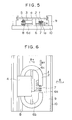
- Figures 5 and 6 of the accompanying drawings show the construction of such vibration wave driven motor. The
reference numeral 1 designates a resilient member having a projection 1 a provided on the sliding surface side thereof, and a piezo-electric element 2 for forming a travelling vibration wave in theresilient member 1 is joined to the upper surface of the resilient member. Thereference numeral 8 denotes a rail-like stator (a driven member) as a contact member which frictionally contacts with theresilient member 1. The rail-like stator 8 is brought into pressure contact with theresilient member 1 by a pressingspring 3 through a vibration insulating material 5 (for example, felt). - The
reference numeral 6 designates a comb-tooth-like movement stopper having its comb-tooth portion 6a inserted in a slit in that portion of theresilient member 1 which is not in contact with the rail-like stator 8. The comb-tooth portion 6a supports theresilient member 1 through felt 7 disposed on the bottom of the slit. - The
resilient member 1 is supported by a supporting table 4 through themovement stopper 6, thepressing spring 3, etc., and the supporting table 4 on which for example, the printing head of a printer is placed is supported by arestraining member 9 for restraining displacement in any other direction than a direction By which is a predetermined movement direction. - When a travelling vibration wave is formed in the
resilient member 1 by two standing waves which deviate by 90 ° in phase and time from each other, theresilient member 1 is moved on the rail-like stator 8 by the frictional force between the rail-like stator 8 andresilient member 1 and along therewith, the supporting table 4 and other members (3, 5, 6 and 7) move in the direction By along the restrainingmember 9. At that time, the frictional driving force produced acts on a portion of theresilient member 1, and since it deviates from the supporting portion, a moment acts on theresilient member 1, which thus tries to deviate in directions Bx and By. - The comb-
tooth portion 6a of themovement stopper 6 is inserted in the slit portion of theresilient member 1 as shown in Figure 6, and restrains the displacement of theresilient member 1 in the direction By and also supports the weight of theresilient member 1 through thefelt 7. Restrainingportions 6b and 6c restrain the displacement of theresilient member 1 in the direction Bx, and a restrainingmember 6d restrains the displacement of theresilient member 1 on the pressed side thereof in the direction By.By virtue of thesemembers 6a - 6d, theresilient member 1 is rectilinearly smoothly movable with the supporting table 4 without back-lash. - Figure 7 of the accompanying drawings is a perspective view of the
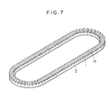
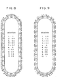
resilient member 1 to which the piezo-electric element 2 is joined, and Figures 8 and 9 of the accompanying drawings are contour maps showing the deviations of the surface of the piezo-electric element in two standing wave modes positionally deviating by 90 from each other and equal in resonance frequency which have been found by eigen value analysis using the finite element method. The deviation is a component in a direction perpendicular to the surface of the piezo- electric element, and the amount of deviation is maximum "1". - This vibration member is such that fifteen waves are generated in the full circumference thereof and about five waves are generated in the straight portions thereof used for driving. Accordingly, the rail-
like stator 8 and theresilient member 1 are in contact with each other at the antinodes of five waves. - Now, generally, the travelling vibration wave generated in the
resilient member 1 is irregular in the magnitude of amplitude from location to location because of the warp of the surfaces of theresilient member 1 and the piezo-electric element 2 and the non-uniformity of the materials thereof. Therefore, where theresilient member 1 and the rail-like stator 8 are in contact with each other at the antinodes of a number of waves, the states of contact in the individual waves differ and in an extreme case, the two members are in contact with each other at some locations and are not in contact with each other at other locations. This irregularity of contact has increased the slide loss on the sliding surface, has reduced the efficiency of the motor and has caused noise. - Reference is made to US Patent No. 4672256 which discloses a vibration wave motor, in which a periodic voltage is applied to an electrostrictive element to generate a travelling vibration wave in the surface of a vibration member thereof, and in which a movable member having a friction member is driven on the vibration member by the vibration wave.
- Reference is also made to Patent Abstracts of Japan 60046781 which discloses a vibration wave motor having electrostrictive elements arranged in such a manner that when an AC voltage is applied thereto, standing waves are generated and combined to form a travelling wave.
- Reference is further made to EP-A-0301430 which discloses an ultrasonic driving device comprising a stator consisting of a piezoelectric vibrator having divided electrodes.
- Reference is still further made to Patent Abstracts of Japan 62077968 which discloses a printer having a piezoelectric motor which generates a flexural vibration to effect a driving motion.
- An object of the present invention is to provide a vibration wave driven apparatus in which any reduction in the efficiency of a motor and the generation of noise can be prevented.
- According to the invention there is provided a vibration wave motor comprising a vibrating member having at lest one elongate straight portion of length L and at least one curved portion of average radius R contiguous with said straight portion, characterised in that R/L is 1/4 or greater.
- A resilient member may be driven while being maintained in stable contact with a rail-like stator and any reduction in the efficiency of the motor and the generation of noise can be prevented.
- The present invention is embodied in a vibration wave driven motor in which the vibration member has an electromechanical energy conversation element secured to one surface of a resilient member of an elliptical annular shape formed by straight portions and arcuate portions, and a member brought into pressure contact with the other surface of said resilient member and wherein AC voltages having a phase difference of 90 therebetween in terms of time are applied to the driving phases of said electro-mechanical energy conversation element divided into two phases to thereby generate a travelling vibration wave in said resilient member, whereby said vibration member and said member brought into pressure contact therewith are moved relative to each other. The two driving phases of said electro-mechanical energy conversion element are polarization-processed in such a manner that only one travelling wave is formed in the straight portions of said resilient member.
-
- Figures 1 to 4 show an embodiment of a vibration wave driven motor according to the present invention, Figure 1 being a perspective view of a vibration member, Figures 2 and 3 being contour maps of the deviation of the standing wave mode by the finite element method, Figure 4 showing the polarization pattern of the piezo-electric element thereof.
- Figures 5 and 6 are a side view and a plan view, respectively, of a vibration wave driven motor according to the prior art.
- Figure 7 is a perspective view of a vibration member according to the prior art.
- Figures 8 and 9 are contour maps of the deviation of two standing wave modes excited in the resilient member of Figure 7.
- Figures 10 and 11 are contour maps of the deviation of the standing wave mode in another embodiment of the present invention.
- Figures 1 to 4 schematically show the essential portions of a bubble jet type printer to which the present invention is applied. The other portions of the printer are identical in construction to those shown in Figures 5 and 6 and therefore are not shown. The bubble jet type printer is a printer as disclosed, for example, in U.S. Patent No. 4,723,129 or U.S. Patent No. 4,740,796. Briefly describing it, it is a printer of the type in which at least one driving signal corresponding to recording information and providing a rapid temperature rise exceeding nuleate boiling is applied to an electro-thermal conversion member diposed correspondingly to a sheet or a liquid path in which liquid (ink) is retained to thereby generate heat energy in the electro-thermal conversion member and cause film boiling on the heat-acting surface of a recording head, with a result that a bubble in the liquid (ink) is formed correspondingly to said driving signal and by the growth and contraction of this bubble, the liquid (ink) is discharged through a discharge opening to form at least one droplet, which is blown against a sheet to thereby form a character.
- In Figure 1, the
reference numeral 1 designates a resilient member formed into an elliptical annular shape. A piezo-electric element 2 as an electro- mechanical energy conversion element is adhesively secured to one surface of theresilient member 1, whereby a vibration member is constructed. The present embodiment is such that six travelling vibration waves are formed in the full circumference of theresilient member 1, and the polarization pattern of the piezo-electric element 2 is shown in Figure 4. The reference characters 2ai and 2a2 denote the segment of the piezo-electric element which form one driving phase (hereinafter referred to as the A group) polarization-processed into the (+) polarity and the (-) polarity, respectively. Thesesegments reference characters segments electric elements resilient member 1 and in the B group as well, only one set of piezo-electric elements resilient member 1, whereby among the six travelling waves over the full circumference, only one travelling wave is formed in each straight portion. AC voltages which are equal in frequency and 90 out of phase with each other in terms of time are applied to the A group and the B group from a driving circuit, not shown, whereby travelling waves are formed on theresilient member 1, and the standing wave mode during the A group driving is shown in Figure 2 and the standing wave mode during the B group driving is shown in Figure 3. - Figures 2 and 3 show the deviations of the respective standing wave modes in contour maps in the same manner as Figures 8 and 9.
- In the present embodiment, the length L of the straight portions is 7 mm and the average radius R of the arcuate portions (the average of the radius of the outer periphery and the radius of the inner periphery) is 5 mm in order to obtain the vibration modes shown in Figures 2 and 3, and by the inventor's experiment, it has been found that if the ratio (R/L) of the average radius R of the arcuate portions to the length L of the straight portions is 1/4 or more, the position of the maximum amplitude of the standing wave in the straight portions of the
resilient member 1 exists on only one of the inner periphery side and the outer periphery side in both of the two vibration modes and when the vibration is made into a travelling wave, the amplitude on one of the outer periphery side and the inner periphery side is always high in the straight portions. In the present embodiment, one travelling wave formed on the straight portions of theresilient member 1 is higher in the amplitude on the outer periphery side. From this, in the case as shown, for example, in Figure 5, the outer periphery side of theresilient member 1 can be brought into pressure contact with the rail-like stator 8 to thereby drive the motor efficiently. - Thus, the travelling wave formed on the
resilient member 1 is such that only one wave is formed in the straight portions and therefore, if such resilient member is applied to the apparatus shown in Figure 5, theresilient member 1 and the rail-like stator 8 always contact with each other at the antinode of one wave without separating from each other and therefore, the reduction in the efficiency of the motor caused by the slide loss on the sliding surface can be decreased and at the same time, the generation of noise can be prevented. - Figures 10 and 11 are contour maps of the deviations of the two standing wave modes of the
resilient member 1 according to another embodiment of the present invention. These are seven waves over the full circumference, and approximately one wave is generated in the straight portions used for driving. - Besides this, the task can be achieved if the piezo-electric element is disposed so that irrespective of the number of waves over the full circumference, approximately one wave may be generated in the straight portions used for driving.
- In the above-described embodiment, the vibration member is moved and the
stator 8 which is a portion of the printer is fixed in place, but alternatively, the vibration member may be fixed in place and thestator 8 may be moved to obtain a similar effect. - As described above, according to the present invention, such a travelling vibration wave that approximately one wave is created in the straight portions of the vibration member used for driving is generated and the vibration member and the member with which the vibration member is brought into pressure contact are always brought into contact with each other at the antinode of one wave without separating from each other, whereby the efficiency of the motor can be enhanced and noise can be prevented.
Claims (8)
Applications Claiming Priority (3)
| Application Number | Priority Date | Filing Date | Title |
|---|---|---|---|
| JP1320127A JPH03183376A (en) | 1989-12-08 | 1989-12-08 | Oscillation wave motor |
| JP320127/89 | 1989-12-08 | ||
| EP90313324A EP0435496B1 (en) | 1989-12-08 | 1990-12-07 | A vibration driven motor and thermal jet type printer using the same |
Related Parent Applications (2)
| Application Number | Title | Priority Date | Filing Date |
|---|---|---|---|
| EP90313324A Division EP0435496B1 (en) | 1989-12-08 | 1990-12-07 | A vibration driven motor and thermal jet type printer using the same |
| EP90313324.7 Division | 1990-12-07 |
Publications (3)
| Publication Number | Publication Date |
|---|---|
| EP0598710A2 true EP0598710A2 (en) | 1994-05-25 |
| EP0598710A3 EP0598710A3 (en) | 1994-11-02 |
| EP0598710B1 EP0598710B1 (en) | 1998-03-11 |
Family
ID=18118003
Family Applications (2)
| Application Number | Title | Priority Date | Filing Date |
|---|---|---|---|
| EP94200301A Expired - Lifetime EP0598710B1 (en) | 1989-12-08 | 1990-12-07 | Vibration driven apparatus and thermal jet type printer incorporating the same |
| EP90313324A Expired - Lifetime EP0435496B1 (en) | 1989-12-08 | 1990-12-07 | A vibration driven motor and thermal jet type printer using the same |
Family Applications After (1)
| Application Number | Title | Priority Date | Filing Date |
|---|---|---|---|
| EP90313324A Expired - Lifetime EP0435496B1 (en) | 1989-12-08 | 1990-12-07 | A vibration driven motor and thermal jet type printer using the same |
Country Status (4)
| Country | Link |
|---|---|
| US (1) | US5155407A (en) |
| EP (2) | EP0598710B1 (en) |
| JP (1) | JPH03183376A (en) |
| DE (2) | DE69032138T2 (en) |
Families Citing this family (20)
| Publication number | Priority date | Publication date | Assignee | Title |
|---|---|---|---|---|
| JPH03183381A (en) * | 1989-12-12 | 1991-08-09 | Canon Inc | Oscillation wave motor |
| US5428260A (en) * | 1990-08-03 | 1995-06-27 | Canon Kabushiki Kaisha | Vibration driven motor |
| JPH0564467A (en) * | 1991-09-05 | 1993-03-12 | Canon Inc | Oscillation wave linear motor |
| JPH05116788A (en) * | 1991-10-29 | 1993-05-14 | Canon Inc | Paper sheet feeding device |
| JPH066986A (en) * | 1992-06-17 | 1994-01-14 | Canon Inc | Oscillation wave motor and manufacture thereof |
| JPH06178560A (en) * | 1992-12-03 | 1994-06-24 | Canon Inc | Vibration wave motor and printer |
| IL104349A (en) * | 1993-01-08 | 1997-01-10 | Mul T Lock Ltd | Locking apparatus |
| JP3155109B2 (en) * | 1993-01-22 | 2001-04-09 | キヤノン株式会社 | Vibration wave driving device and printer device |
| US6628046B2 (en) | 1997-05-27 | 2003-09-30 | Canon Kabushiki Kaisha | Vibration type actuator |
| US6404104B1 (en) | 1997-11-27 | 2002-06-11 | Canon Kabushiki Kaisha | Vibration type actuator and vibration type driving apparatus |
| JP4328412B2 (en) | 1999-05-14 | 2009-09-09 | キヤノン株式会社 | Vibration type actuator and vibration type drive device |
| JP4726167B2 (en) * | 2001-03-12 | 2011-07-20 | キヤノン株式会社 | Vibration wave drive |
| JP4731723B2 (en) * | 2001-05-24 | 2011-07-27 | キヤノン株式会社 | Method for manufacturing vibration wave drive device |
| JP4027090B2 (en) * | 2001-12-27 | 2007-12-26 | キヤノン株式会社 | Vibration body and vibration wave drive device |
| JP4756916B2 (en) * | 2005-05-31 | 2011-08-24 | キヤノン株式会社 | Vibration wave motor |
| DE102012022146A1 (en) | 2012-11-12 | 2014-05-15 | Physik Instrumente (Pi) Gmbh & Co. Kg | Ultrasonic actuator for a linear ultrasonic motor and linear ultrasonic motor with an ultrasonic actuator |
| US10516091B2 (en) | 2015-11-27 | 2019-12-24 | Canon Kabushiki Kaisha | Ultrasonic motor, drive control system, optical apparatus, and vibrator |
| US10775681B2 (en) | 2015-11-27 | 2020-09-15 | Canon Kabushiki Kaisha | Ultrasonic motor, drive control system, optical apparatus, and vibrator |
| US10536097B2 (en) | 2015-11-27 | 2020-01-14 | Canon Kabushiki Kaisha | Ultrasonic motor, drive control system, optical apparatus, and vibrator |
| US10451833B2 (en) | 2015-11-27 | 2019-10-22 | Canon Kabushiki Kaisha | Ultrasonic motor, drive control system, optical apparatus, and vibrator |
Citations (6)
| Publication number | Priority date | Publication date | Assignee | Title |
|---|---|---|---|---|
| DE3415628A1 (en) * | 1983-04-30 | 1984-10-31 | Canon K.K., Tokio/Tokyo | VIBRATION SHAFT MOTOR |
| JPS6046781A (en) * | 1983-08-24 | 1985-03-13 | Canon Inc | Vibration wave motor |
| EP0169297A2 (en) * | 1984-03-01 | 1986-01-29 | Matsushita Electric Industrial Co., Ltd. | Piezoelectric motor |
| JPS6277968A (en) * | 1985-10-02 | 1987-04-10 | Nec Corp | Printer |
| US4672256A (en) * | 1984-12-26 | 1987-06-09 | Canon Kabushiki Kaisha | Linear vibration wave motor |
| US4723129A (en) * | 1977-10-03 | 1988-02-02 | Canon Kabushiki Kaisha | Bubble jet recording method and apparatus in which a heating element generates bubbles in a liquid flow path to project droplets |
Family Cites Families (12)
| Publication number | Priority date | Publication date | Assignee | Title |
|---|---|---|---|---|
| JPS6118371A (en) * | 1984-07-03 | 1986-01-27 | Matsushita Electric Ind Co Ltd | Piezoelectric motor |
| US4692652A (en) * | 1985-03-29 | 1987-09-08 | Canon Kabushiki Kaisha | Vibration wave motor |
| JPS61224880A (en) * | 1985-03-29 | 1986-10-06 | Canon Inc | Vibration wave motor |
| JPS6277969A (en) * | 1985-10-02 | 1987-04-10 | Nec Corp | Printer |
| JP2555122B2 (en) * | 1987-02-02 | 1996-11-20 | 株式会社日立製作所 | Portable dosimeter |
| JPS63213480A (en) * | 1987-02-27 | 1988-09-06 | Nec Corp | Ultrasonic motor |
| JPS63294273A (en) * | 1987-05-25 | 1988-11-30 | Jgc Corp | Ultrasonic wave driving device |
| US4945275A (en) * | 1987-07-26 | 1990-07-31 | Honda Electric Co., Ltd. | Ultrasonic driving device |
| JPS6417669A (en) * | 1987-12-03 | 1989-01-20 | Nitta Kk | Glasses for golf exercise |
| JPH0268465A (en) * | 1988-08-31 | 1990-03-07 | Shirakawa Shiro | Cooling and heating device |
| JPH02285974A (en) * | 1989-04-25 | 1990-11-26 | Canon Inc | Vibration wave motor |
| JPH0321879A (en) * | 1989-06-20 | 1991-01-30 | Hitachi Electron Eng Co Ltd | Timing signal generating circuit of tester |
-
1989
- 1989-12-08 JP JP1320127A patent/JPH03183376A/en active Pending
-
1990
- 1990-12-07 EP EP94200301A patent/EP0598710B1/en not_active Expired - Lifetime
- 1990-12-07 US US07/623,571 patent/US5155407A/en not_active Expired - Fee Related
- 1990-12-07 EP EP90313324A patent/EP0435496B1/en not_active Expired - Lifetime
- 1990-12-07 DE DE69032138T patent/DE69032138T2/en not_active Expired - Fee Related
- 1990-12-07 DE DE69023752T patent/DE69023752T2/en not_active Expired - Fee Related
Patent Citations (6)
| Publication number | Priority date | Publication date | Assignee | Title |
|---|---|---|---|---|
| US4723129A (en) * | 1977-10-03 | 1988-02-02 | Canon Kabushiki Kaisha | Bubble jet recording method and apparatus in which a heating element generates bubbles in a liquid flow path to project droplets |
| DE3415628A1 (en) * | 1983-04-30 | 1984-10-31 | Canon K.K., Tokio/Tokyo | VIBRATION SHAFT MOTOR |
| JPS6046781A (en) * | 1983-08-24 | 1985-03-13 | Canon Inc | Vibration wave motor |
| EP0169297A2 (en) * | 1984-03-01 | 1986-01-29 | Matsushita Electric Industrial Co., Ltd. | Piezoelectric motor |
| US4672256A (en) * | 1984-12-26 | 1987-06-09 | Canon Kabushiki Kaisha | Linear vibration wave motor |
| JPS6277968A (en) * | 1985-10-02 | 1987-04-10 | Nec Corp | Printer |
Non-Patent Citations (2)
| Title |
|---|
| PATENT ABSTRACTS OF JAPAN vol. 11, no. 278 (M-623) 9 September 1987 & JP-A-62 077 968 (NEC) 10 April 1987 * |
| PATENT ABSTRACTS OF JAPAN vol. 9, no. 173 (E-329) 18 July 1985 & JP-A-60 046 781 (CANON) 13 March 1985 * |
Also Published As
| Publication number | Publication date |
|---|---|
| DE69032138T2 (en) | 1998-07-30 |
| DE69032138D1 (en) | 1998-04-16 |
| EP0598710B1 (en) | 1998-03-11 |
| US5155407A (en) | 1992-10-13 |
| DE69023752T2 (en) | 1996-05-02 |
| EP0435496A1 (en) | 1991-07-03 |
| EP0435496B1 (en) | 1995-11-22 |
| DE69023752D1 (en) | 1996-01-04 |
| EP0598710A3 (en) | 1994-11-02 |
| JPH03183376A (en) | 1991-08-09 |
Similar Documents
| Publication | Publication Date | Title |
|---|---|---|
| EP0435496B1 (en) | A vibration driven motor and thermal jet type printer using the same | |
| US5039899A (en) | Piezoelectric transducer | |
| US7109639B2 (en) | Vibration-type driving device, control apparatus for controlling the driving of the vibration-type driving device, and electronic equipment having the vibration-type driving device and the control apparatus | |
| US4580073A (en) | Vibration wave motor with plural projection vibrator | |
| JP4261964B2 (en) | Vibration type driving device and control system | |
| US4587452A (en) | Vibration wave motor having a vibrator of non-uniform elastic modulus | |
| US4692652A (en) | Vibration wave motor | |
| JPH0389875A (en) | Linear ultrasonic motor | |
| EP0450919A1 (en) | Vibration wave driven motor | |
| EP0495665A1 (en) | Ultrasonic stepping motor | |
| US5583390A (en) | Vibration wave driven apparatus | |
| US5274294A (en) | Vibration wave driven motor | |
| US5041750A (en) | Vibration wave driven apparatus | |
| EP0530822B1 (en) | Guide device for vibration driven motor | |
| EP0718899A2 (en) | Vibration actuator | |
| US5455478A (en) | Vibration wave driven apparatus | |
| JPS62259485A (en) | Piezoelectric driving apparatus | |
| JPS63316675A (en) | Piezoelectric linear motor | |
| US5499808A (en) | Sheet feeding apparatus | |
| JPH05191988A (en) | Ultrasonic oscillator | |
| JPS61221584A (en) | Drive circuit of vibration wave motor | |
| JPH0417584A (en) | Ultrasonic actuator | |
| JPH0552137B2 (en) | ||
| JPH09117166A (en) | Ultrasonic motor | |
| JPH02146971A (en) | Piezoelectric motor and drive method of piezoelectric motor |
Legal Events
| Date | Code | Title | Description |
|---|---|---|---|
| PUAI | Public reference made under article 153(3) epc to a published international application that has entered the european phase |
Free format text: ORIGINAL CODE: 0009012 |
|
| AC | Divisional application: reference to earlier application |
Ref document number: 435496 Country of ref document: EP |
|
| AK | Designated contracting states |
Kind code of ref document: A2 Designated state(s): DE FR GB IT NL |
|
| PUAL | Search report despatched |
Free format text: ORIGINAL CODE: 0009013 |
|
| AK | Designated contracting states |
Kind code of ref document: A3 Designated state(s): DE FR GB IT NL |
|
| 17P | Request for examination filed |
Effective date: 19950324 |
|
| 17Q | First examination report despatched |
Effective date: 19960125 |
|
| GRAG | Despatch of communication of intention to grant |
Free format text: ORIGINAL CODE: EPIDOS AGRA |
|
| RTI1 | Title (correction) | ||
| GRAG | Despatch of communication of intention to grant |
Free format text: ORIGINAL CODE: EPIDOS AGRA |
|
| GRAH | Despatch of communication of intention to grant a patent |
Free format text: ORIGINAL CODE: EPIDOS IGRA |
|
| GRAH | Despatch of communication of intention to grant a patent |
Free format text: ORIGINAL CODE: EPIDOS IGRA |
|
| GRAA | (expected) grant |
Free format text: ORIGINAL CODE: 0009210 |
|
| AC | Divisional application: reference to earlier application |
Ref document number: 435496 Country of ref document: EP |
|
| AK | Designated contracting states |
Kind code of ref document: B1 Designated state(s): DE FR GB IT NL |
|
| PG25 | Lapsed in a contracting state [announced via postgrant information from national office to epo] |
Ref country code: IT Free format text: LAPSE BECAUSE OF FAILURE TO SUBMIT A TRANSLATION OF THE DESCRIPTION OR TO PAY THE FEE WITHIN THE PRE;WARNING: LAPSES OF ITALIAN PATENTS WITH EFFECTIVE DATE BEFORE 2007 MAY HAVE OCCURRED AT ANY TIME BEFORE 2007. THE CORRECT EFFECTIVE DATE MAY BE DIFFERENT FROM THE ONE RECORDED.SCRIBED TIME-LIMIT Effective date: 19980311 |
|
| REF | Corresponds to: |
Ref document number: 69032138 Country of ref document: DE Date of ref document: 19980416 |
|
| ET | Fr: translation filed | ||
| PLBE | No opposition filed within time limit |
Free format text: ORIGINAL CODE: 0009261 |
|
| STAA | Information on the status of an ep patent application or granted ep patent |
Free format text: STATUS: NO OPPOSITION FILED WITHIN TIME LIMIT |
|
| 26N | No opposition filed | ||
| REG | Reference to a national code |
Ref country code: GB Ref legal event code: IF02 |
|
| PGFP | Annual fee paid to national office [announced via postgrant information from national office to epo] |
Ref country code: GB Payment date: 20031124 Year of fee payment: 14 |
|
| PGFP | Annual fee paid to national office [announced via postgrant information from national office to epo] |
Ref country code: NL Payment date: 20031215 Year of fee payment: 14 |
|
| PGFP | Annual fee paid to national office [announced via postgrant information from national office to epo] |
Ref country code: FR Payment date: 20031222 Year of fee payment: 14 |
|
| PGFP | Annual fee paid to national office [announced via postgrant information from national office to epo] |
Ref country code: DE Payment date: 20031223 Year of fee payment: 14 |
|
| PG25 | Lapsed in a contracting state [announced via postgrant information from national office to epo] |
Ref country code: GB Free format text: LAPSE BECAUSE OF NON-PAYMENT OF DUE FEES Effective date: 20041207 |
|
| PG25 | Lapsed in a contracting state [announced via postgrant information from national office to epo] |
Ref country code: NL Free format text: LAPSE BECAUSE OF NON-PAYMENT OF DUE FEES Effective date: 20050701 Ref country code: DE Free format text: LAPSE BECAUSE OF NON-PAYMENT OF DUE FEES Effective date: 20050701 |
|
| GBPC | Gb: european patent ceased through non-payment of renewal fee |
Effective date: 20041207 |
|
| PG25 | Lapsed in a contracting state [announced via postgrant information from national office to epo] |
Ref country code: FR Free format text: LAPSE BECAUSE OF NON-PAYMENT OF DUE FEES Effective date: 20050831 |
|
| NLV4 | Nl: lapsed or anulled due to non-payment of the annual fee |
Effective date: 20050701 |
|
| REG | Reference to a national code |
Ref country code: FR Ref legal event code: ST |