EP0587903B1 - Mold for manufacturing very thin rubber molding and method of manufacturing the mold - Google Patents
Mold for manufacturing very thin rubber molding and method of manufacturing the mold Download PDFInfo
- Publication number
- EP0587903B1 EP0587903B1 EP93904328A EP93904328A EP0587903B1 EP 0587903 B1 EP0587903 B1 EP 0587903B1 EP 93904328 A EP93904328 A EP 93904328A EP 93904328 A EP93904328 A EP 93904328A EP 0587903 B1 EP0587903 B1 EP 0587903B1
- Authority
- EP
- European Patent Office
- Prior art keywords
- mold
- shaping
- latex
- molds
- heat
- Prior art date
- Legal status (The legal status is an assumption and is not a legal conclusion. Google has not performed a legal analysis and makes no representation as to the accuracy of the status listed.)
- Expired - Lifetime
Links
Images


Classifications
-
- B—PERFORMING OPERATIONS; TRANSPORTING
- B29—WORKING OF PLASTICS; WORKING OF SUBSTANCES IN A PLASTIC STATE IN GENERAL
- B29C—SHAPING OR JOINING OF PLASTICS; SHAPING OF MATERIAL IN A PLASTIC STATE, NOT OTHERWISE PROVIDED FOR; AFTER-TREATMENT OF THE SHAPED PRODUCTS, e.g. REPAIRING
- B29C33/00—Moulds or cores; Details thereof or accessories therefor
- B29C33/02—Moulds or cores; Details thereof or accessories therefor with incorporated heating or cooling means
-
- B—PERFORMING OPERATIONS; TRANSPORTING
- B29—WORKING OF PLASTICS; WORKING OF SUBSTANCES IN A PLASTIC STATE IN GENERAL
- B29C—SHAPING OR JOINING OF PLASTICS; SHAPING OF MATERIAL IN A PLASTIC STATE, NOT OTHERWISE PROVIDED FOR; AFTER-TREATMENT OF THE SHAPED PRODUCTS, e.g. REPAIRING
- B29C33/00—Moulds or cores; Details thereof or accessories therefor
- B29C33/38—Moulds or cores; Details thereof or accessories therefor characterised by the material or the manufacturing process
-
- B—PERFORMING OPERATIONS; TRANSPORTING
- B29—WORKING OF PLASTICS; WORKING OF SUBSTANCES IN A PLASTIC STATE IN GENERAL
- B29C—SHAPING OR JOINING OF PLASTICS; SHAPING OF MATERIAL IN A PLASTIC STATE, NOT OTHERWISE PROVIDED FOR; AFTER-TREATMENT OF THE SHAPED PRODUCTS, e.g. REPAIRING
- B29C41/00—Shaping by coating a mould, core or other substrate, i.e. by depositing material and stripping-off the shaped article; Apparatus therefor
- B29C41/02—Shaping by coating a mould, core or other substrate, i.e. by depositing material and stripping-off the shaped article; Apparatus therefor for making articles of definite length, i.e. discrete articles
- B29C41/14—Dipping a core
-
- B—PERFORMING OPERATIONS; TRANSPORTING
- B29—WORKING OF PLASTICS; WORKING OF SUBSTANCES IN A PLASTIC STATE IN GENERAL
- B29C—SHAPING OR JOINING OF PLASTICS; SHAPING OF MATERIAL IN A PLASTIC STATE, NOT OTHERWISE PROVIDED FOR; AFTER-TREATMENT OF THE SHAPED PRODUCTS, e.g. REPAIRING
- B29C41/00—Shaping by coating a mould, core or other substrate, i.e. by depositing material and stripping-off the shaped article; Apparatus therefor
- B29C41/34—Component parts, details or accessories; Auxiliary operations
- B29C41/46—Heating or cooling
-
- B—PERFORMING OPERATIONS; TRANSPORTING
- B29—WORKING OF PLASTICS; WORKING OF SUBSTANCES IN A PLASTIC STATE IN GENERAL
- B29C—SHAPING OR JOINING OF PLASTICS; SHAPING OF MATERIAL IN A PLASTIC STATE, NOT OTHERWISE PROVIDED FOR; AFTER-TREATMENT OF THE SHAPED PRODUCTS, e.g. REPAIRING
- B29C35/00—Heating, cooling or curing, e.g. crosslinking or vulcanising; Apparatus therefor
- B29C35/02—Heating or curing, e.g. crosslinking or vulcanizing during moulding, e.g. in a mould
- B29C2035/0211—Heating or curing, e.g. crosslinking or vulcanizing during moulding, e.g. in a mould resistance heating
-
- B—PERFORMING OPERATIONS; TRANSPORTING
- B29—WORKING OF PLASTICS; WORKING OF SUBSTANCES IN A PLASTIC STATE IN GENERAL
- B29C—SHAPING OR JOINING OF PLASTICS; SHAPING OF MATERIAL IN A PLASTIC STATE, NOT OTHERWISE PROVIDED FOR; AFTER-TREATMENT OF THE SHAPED PRODUCTS, e.g. REPAIRING
- B29C33/00—Moulds or cores; Details thereof or accessories therefor
- B29C33/76—Cores
-
- B—PERFORMING OPERATIONS; TRANSPORTING
- B29—WORKING OF PLASTICS; WORKING OF SUBSTANCES IN A PLASTIC STATE IN GENERAL
- B29K—INDEXING SCHEME ASSOCIATED WITH SUBCLASSES B29B, B29C OR B29D, RELATING TO MOULDING MATERIALS OR TO MATERIALS FOR MOULDS, REINFORCEMENTS, FILLERS OR PREFORMED PARTS, e.g. INSERTS
- B29K2707/00—Use of elements other than metals for preformed parts, e.g. for inserts
- B29K2707/04—Carbon
-
- B—PERFORMING OPERATIONS; TRANSPORTING
- B29—WORKING OF PLASTICS; WORKING OF SUBSTANCES IN A PLASTIC STATE IN GENERAL
- B29L—INDEXING SCHEME ASSOCIATED WITH SUBCLASS B29C, RELATING TO PARTICULAR ARTICLES
- B29L2031/00—Other particular articles
- B29L2031/753—Medical equipment; Accessories therefor
- B29L2031/7538—Condoms
-
- Y—GENERAL TAGGING OF NEW TECHNOLOGICAL DEVELOPMENTS; GENERAL TAGGING OF CROSS-SECTIONAL TECHNOLOGIES SPANNING OVER SEVERAL SECTIONS OF THE IPC; TECHNICAL SUBJECTS COVERED BY FORMER USPC CROSS-REFERENCE ART COLLECTIONS [XRACs] AND DIGESTS
- Y10—TECHNICAL SUBJECTS COVERED BY FORMER USPC
- Y10S—TECHNICAL SUBJECTS COVERED BY FORMER USPC CROSS-REFERENCE ART COLLECTIONS [XRACs] AND DIGESTS
- Y10S425/00—Plastic article or earthenware shaping or treating: apparatus
- Y10S425/013—Electric heat
Definitions
- the present invention relates to a shaping mold for production of ultra-thin shaped rubber articles, for example, condoms as a contraceptive device, medical rubber gloves to be used in the field of medical treatment such as surgical rubber gloves, and working rubber gloves to be used in the working filed of high-technology industry or the like so as to create a clean working environment therein and also to accurately carry out fine works therein, and it also relates to a method for producing such ultra-thin shaped rubber articles by the use of the shaping molds.
- Ultra-thin shaped rubber articles such as condoms and others are generally produced by a process of using shaping molds made of glass or porcelain, a number of which shaping molds are mounted on an endless belt at determined intervals.
- the process comprises several steps, namely a washing step of washing the shaping molds with water in a washing tank, a dipping step of dipping the shaping molds successively in a latex liquid so as to make the latex adhere to the surfaces of the shaping molds, a heat-drying step of heating and drying the latex as adhered to the surfaces of the shaping molds for curing it thereon, and an inspecting step of dipping the shaped articles as shaped with the shaping molds in an electrolytic solution for effecting pin hole inspection of the articles by applying an electric current to the solution.
- the shaped article as adhered to the surface of the shaping mold is released from the surface after the heat-drying step, the released article is again mounted on an electroconductive inspecting mold for its pin hole inspection, and it must be dipped in an electrolytic solution when it is on the mold whilst applying an electric current to the solution for the inspection. Since the shaped article is an ultra-thin rubber article, the operation of peeling the shaped article from the shaping mold and of re-mounting the article to the inspecting mold in the inspecting step is extremely troublesome. Therefore, the inspecting step has been a stage at which there is serious retarding of the process of producing ultra-thin shaped articles such as condoms and others.
- a shaping mold for producing ultra-thin shaped rubber articles which shaping mold is made of an electroconductive ceramic material of SiC or ZrB 2 or a mixture of them so that it may directly be used also as an inspecting mold as it is, whereby the troublesome operation of "peeling the shaped article from the shaping mold followed by re-mounting the article to a different inspecting mold" may be omitted (Japanese Patent Application Laid-Open No. 1-108,012).
- the problem that metal ions go into the latex in the dipping step may be overcome and production of ultra-thin shaped rubber articles may be effected continuously from the washing step to the successive dipping step, heat-drying step and inspecting step in order.
- the use of the shaping mold therefore yields a benefit of improving the production efficiency.
- the shaping mold is made of an electroconductive ceramic material in this way, not only is the electroconductive ceramic material high-priced of itself but also it has a large specific gravity. Therefore, the shaping mold is unsuitable for constituting a production line having therein a large amount of shaping molds mounted on an endless belt.
- the shape of the mold to be made of the material is limited. If a shaping mold having a possibly complicated shape is desired to be made of the material, polishing is needed for grinding or mirror-finishing the surface of the mold, which causes another problem of requiring much labor and cost for the grinding and mirror-finishing. For these reasons, the proposed shaping mold could not be said to be always satisfactory.
- a binder is incorporated into a powder of the ceramic material to prepare a compound, the compound is shaped into a non-sintered shaped body having the same shape as the intended shaping mold, and the non-sintered shaped body thus obtained is then sintered at a determined sintering temperature to give the intended shaping body made of an electroconductive ceramic material.
- the non-sintered shaped body may not be sufficiently easily workable for its surface to be ground to various shapes or for its surface to be polished to a mirror-finish, but rather the surface of the sintered body having a high hardness must be ground or mirror-finished by polishing.
- the thickness of the shaped articles to be produced by the process is extremely small so that pin holes are easily formed in the shaped articles when the solvent is removed form the latex as adhered to the surface of the shaping mold in the heat-drying step. This is still another problem.
- the thickness of them is generally extremely small or is approximately from 0.02 mm to 0.1 mm and production of defective articles having pin holes is not allowable because of their required characteristics so that the inspecting step for pin hole inspection of all the produced articles is indispensable. Therefore, in the process of producing such ultra-thin shaped rubber articles, an important theme is also how to prevent formation of pin holes during the steps of the production and how to increase the yield of the articles.
- one object of the present invention is to provide a novel shaping mold for production of ultra-thin shaped rubber articles, with which mold such a troublesome operation of "peeling a shaped article from the shaping mold followed by re-mounting it on a different inspecting mold for its inspection" in the inspecting step may be omitted, while preventing as much as possible formation of pin holes in the shaped article in the successive steps.
- Another object of the present invention is to provide a novel method of producing ultra-thin shaped rubber articles, using such a shaping mold for production of ultra-thin shaped rubber articles, which method does not need a troublesome operation of "peeling a shaped article from the shaping mold followed by re-mounting it on a different inspecting mold for its inspection” in the inspecting step, while preventing as much as possible formation of pin holes in the shaped article in the successive steps.
- JP-A-2 30507 a shaping mold for production of ultra-thin shaped rubber articles, the main body of which mold is to be dipped in a latex liquid so as to make the latex adhere to the surface of the main body with the adhered latex being heat-dried to form an ultra-thin shaped rubber article over the surface.
- such a shaping mold characterised in that at least the surface of its main body to be dipped in the latex liquid is made of an amorphous carbon and in that its bottom part, which is not to be dipped in the latex liquid, is provided with electrifying electrodes defining therebetween a heating area to be heated by resistance heating due to its electrification.
- the shaping mold is lightweight and is readily workable to be easily shaped to various shapes. Especially, the mirror finish of the surface of the mold is easy, which is requisite to a shaping mold for production of condoms.
- the mold of the present invention is made of an amorphous carbon, but the parts of the mold other than the surface of the main body thereof may be made of either an amorphous carbon like the surface of the main body or any other material such as, for example, ordinary graphite materials, ceramics, electroconductive ceramics, glass, porcelain and the like. If the necessary mechanical strength of the shaping mold is ensured, the mold may be hollow.
- the amorphous carbon forming the main body of the mold has a bulk density of generally from 1.0 g/cm 3 to 1.9 g/cm 3 , which is lower than that of glass or porcelain and is much lower than that of electroconductive ceramics. Accordingly, the shaping mold may be lightweight.
- the bottom part of the shaping mold has a heating area to be heated by resistance heating due to its electrification in order that heating from the side of the shaping mold is possible when the latex adhered to the surface of the main body of the mold is heat-dried.
- At least the heating area to be formed in the bottom part is preferably desired to have an intrinsic resistivity of from 0.00001 ⁇ .cm to 0.1 ⁇ .cm, preferably from 0.0001 ⁇ .cm to 0.01 ⁇ .cm, and the heat transfer coefficient from the heating area of the bottom part to the main body is preferably desired to be from 0.00001 cal/cm.sec.°C to 10 cal/cm.sec.°C, preferably from 0.0001 cal/cm.sec.°C to 5 cal/cm.sec.°C.
- the heat as generated in the heating area of the bottom part may be efficiently transferred to the main body in which the latex adhered to the main body may be heat-dried advantageously.
- the bottom part of the shaping mold may be modified for the purpose of elevating the electric resistance of the part in order to ensure sufficient resistance heating in the heating area to be formed in the part.
- the bottom part may be made of a different material having a high electric resistance, or it may have a double-spiral structure so as to elevate the electric resistance of the part, or additives such as ceramics, glass or the like may be added thereto so as to also elevate the electric resistance of the part.
- the bottom part is fitted with electrodes so as to electrify the above-mentioned heating area therewith or to electrify the main body therewith for pin hole inspection of the shaped article as formed on the surface of the body.
- the part may be fitted with leading electrodes having a substrate of, for example, carbon, plastics, metals, glass, ceramics or the like, as attached thereto with an electroconductive adhesive such as BT-101 (trade name by NISSHINBO INDUSTRIES, INC. ); or it may be wound with a band-like amorphous carbon.
- At least the surface of the main body of the shaping mold of the present invention, which is dipped in a latex liquid in its use, is made of an amorphous carbon.
- an amorphous carbon for use in the present invention may be produced by carbonizing, for example, a high polymer material such as phenolic resins, polyacrylonitriles, polyimides, polyvinyl chlorides, polycarbodiimides, polyvinylidene chlorides, furan resins and the like by conventional known methods.
- amorphous carbon is a method using polycarbodiimide as a starting material, for example, the methods as described in Japanese Patent Application Laid-Open Nos. 2-152167 and 3-247504.
- the amorphous carbon as produced by the methods has the advantage of low porosity and high mechanical strength.
- the method of producing ultra-thin shaped rubber articles, using the above-mentioned shaping mold at least comprises (a) a dipping step of successively dipping the shaping molds in a latex liquid so as to make the latex adhere to the surfaces of the shaping molds, (b) a heat-drying step of electrifying the shaping molds so as to heat their heating areas by resistance heating to thereby heat and dry the latex as adhered to the surfaces of the shaping molds, and (c) an inspecting step of directly dipping the shaped articles as shaped on the shaping molds in an electrolytic solution, without removing them from the molds, followed by electrifying the molds for effecting pin hole inspection of the shaped articles.
- the latex to be used in the above-mentioned dipping method (a) is not specifically defined but it may be a latex of, for example, natural rubber as well as butadiene-styrene synthetic rubber (SBR), butadiene-acrylonitrile synthetic rubber (NBR), butyl rubber, chloroprene rubber (CR), silicone rubber, polyacrylic rubber, fluorine-containing rubber, polyurethane rubber, polyisoprene, Hypalon rubber or the like.
- SBR butadiene-styrene synthetic rubber
- NBR butadiene-acrylonitrile synthetic rubber
- CR chloroprene rubber
- silicone rubber silicone rubber
- polyacrylic rubber fluorine-containing rubber
- fluorine-containing rubber fluorine-containing rubber
- polyurethane rubber polyisoprene
- Hypalon rubber Hypalon rubber
- the bottom part of the shaping mold is electrified so as to heat the heating area to a determined temperature, and the main body to which the latex has adhered is heated due to the thermal conduction from the bottom part to the main body whereby the latex as adhered to the main body is heated and dried from its inside.
- the heat-drying step is combined with external heating with an electric furnace or the like, like a conventional heating step, whereby the whole of the adhered latex may be uniformly heated and dried under the condition free from any extreme temperature difference in the direction of its thickness so that formation of pin holes in the dried latex may be prevented more surely.
- the heating temperature at the main body of the shaping mold the heating temperature by the external heating and the heating times for the heating may suitably be defined, depending upon the kind of the latex as used as well as the amount of the latex as adhered to the main body.
- the heating temperature at the main body may be approximately from 80°C to 170°C
- the heating temperature by the external heating may be approximately from 80°C to 170°C.
- the shaped article as formed on the surface of the main body of the shaping mold in this way is then subjected to pin hole inspection in the next inspecting step (c).
- pin hole inspection is effected in such a way that the shaped article to be inspected is covered over an inspecting mold, and the mold is dipped in an electrolytic solution and then electrified therethrough to check as to whether or not passing of the applied electricity is observed. If the passing of the applied electricity is observed in the test, the shaped article has some pin hole(s) in somewhere and it is dealt with as a defective article.
- the shaping mold having thereon the shaped article as adhered to the surface of the main body thereof is directly dipped in an electrolytic solution and the shaping mold is used as the inspecting mold.
- the precise inspecting method and conditions in the step those of a conventional known method may be used.
- Fig. 1 shows a condom-producing line of one embodiment of the present invention.
- the condom-producing line is basically composed of an endless belt 2 on which a number of shaping molds 1 for producing condoms of the present invention have been mounted, a washing tank 3 for washing the shaping molds 1, a latex liquid tank 4 where the main bodies of the washed shaping molds 1 are dipped in a latex liquid therein, a pre-heating room 5 where the latex as adhered to the main bodies of the shaping molds 1 is preliminarily heated and dried, a heat-drying room 6 where the shaped articles as pre-heated in the pre-heating room 5 are again heated and dried after the upper portion of each pre-heated shaped article has been rolled with fingers to form a reinforced part at the opening of the product to be a condom, an electrolytic solution tank 7 where the condom as dried in the heat-drying room 6 and adhered to the surface of the main body of the shaping mold 1 is subjected to pin hole inspection, a
- each shaping mold 1 is electrified so as to heat the heating area thereof by resistance heating in addition to the external heating to the molds whereby the latex or semi-dried latex as adhered to the surface of the shaping molds 1 is heat-dried and cured.
- electrolytic solution tank 7 a direct current voltage for pin hole inspection is applied between the contact electrode 7a, which is kept in contact with the shaping mold 1, and the electrode 7b, which has been disposed in the electrolytic solution.
- the shaping molds 1 pass through the electrolytic solution in the electrolytic solution tank 7, an electric current flows therethrough via pin hole(s), if any, of the condom as adhered to the main body of the shaping mold 1 so that the condom is detected to be a defective one as having pin hole(s).
- the tank 7 is so constituted that the information derived from the detection is transmitted to the peeling device 9 so as to remove the defective condoms.
- the body of the shaping mold 1 as used in Example 1 is, as shown in Fig. 2, composed of the main body M which is dipped in a latex liquid in its use and the bottom part B which is above the main body M and is not dipped in a latex liquid.
- the main body M add the bottom part B are composed of the core part 1b made of an isotropic graphite material and the surface part 1a of an amorphous carbon as laminated over the surface of the part 1b.
- the upper portion of the mold body is fitted with a heating electrode 11 which is to be connected to the alternating current heating source 10 when the shaping mold 1 is in the pre-heating room 5 and the heat-drying room 6 and also with a band-like electrode 12 made of an amorphous carbon with maintaining the heating area R from the heating electrode 11.
- the band-like electrode 12 made of an amorphous carbon is not only one electrode to be connected to the above-mentioned alternating current heating source 10 but also acts as a contact terminal which is brought into contact with the contact electrode 7a of the direct current voltage source 13 for pin hole inspection of shaped condoms while the shaping mold 1 is passing through the electrolytic solution tank 7, whereupon it short-circuits with the electrode 7b as disposed in the electrolytic solution in the electrolytic solution tank 7 when the shaped condom has some pin hole(s).
- the main body M of the shaping mold 1 of Example 1 is dipped in the latex liquid in the latex liquid tank 4. After the latex liquid tank 4, a determined amount of a latex L has adhered to the surface of the main body M to form a film of a determined thickness. Then, it is preliminarily heated and dried in the pre-heating room 5 and thereafter completely heated and dried in the heat-drying room 6, whilst the upper portion of the shaped film is rolled with fingers, as shown in Fig. 4, to form the reinforced part 14 at the opening of the shaped product condom C.
- methylenediphenyl diisocyanate (MDI) were reacted at 120°C for 6 hours in 820 ml of tetrachloroethylene in the presence of a carbodiimidating catalyst (1-phenyl-3-methylphospholene oxide), and the obtained reaction mixture was cooled to room temperature to precipitate the formed polycarbodiimide, which was then filtered. The precipitates thus obtained were dried at 100°C for 2 hours to obtain a polycarbodiimide powder.
- MDI methylenediphenyl diisocyanate
- An isotropic graphite material (having a bulk density of 1.83 g/cm 3 and a flexural strength of 500 kg/cm 2 ) was worked into a shape of the core part 1b of Fig. 2, and the polycarbodiimide solution as obtained in the above-mentioned Preparation Example 1 was coated over its surface by spray coating. Then, this was dried at 80°C for 3 hours, at 120°C for 4 hours and at 200°C for one hour.
- the shaped body thus formed was heated in nitrogen gas from room temperature up to 1,000°C, 1,500°C, 2,000°C or 2,500°C each at a temperature-elevating rate of 10°C/min and was carbonized at the elevated temperature, whereby the surface layer 1a of amorphous carbon was laminated over the core part 1b.
- the thickness of the surface layer 1a thus formed was from 1 to 3 ⁇ m.
- the shaping mold 1 thus formed was checked with respect to the wettability with a natural rubber latex liquid, the intrinsic resistivity value and the thermal conductivity. The results obtained are shown in Table 1 below.
- the polycarbodiimide solution as obtained in Preparation Example 1 was concentrated with an evaporator to have a resin solid content of 50 % by weight.
- the thus obtained high-concentration polycarbodiimide solution was cast into a mold and heat-treated therein at 60°C for 20 hours, at 80°C for 20 hours and at 120°C for 20 hours.
- the shaped body was released from the mold to obtain a hollow-shaped polycarbodiimide resin body of Fig. 5.
- the shaped polycarbodiimide resin body was heated in nitrogen gas from room temperature up to 1,000°C, 1,500°C, 2,000°C or 2,500°C each at a temperature-elevating rate of 0.2°C/min and was carbonized at the elevated temperature.
- a hollow shaping mold 1 wholly made of an amorphous carbon was formed, as shown in Fig. 5.
- the shaping mold 1 thus formed was checked with respect to the wettability with a natural rubber latex liquid, the intrinsic resistivity value and the thermal conductivity. The results obtained are shown in Table 1 below.
- the polycarbodiimide powder as obtained in Preparation Example 2 was put in a mold and shaped under heat and pressure under the condition of 180°C and 80 kg/cm 2 , and this was cooled to room temperature and released from the mold to obtain a shaped polycarbodiimide resin body having the shape of Fig. 6.
- the surface of the shaped polycarbodiimide resin body was ground to mirror finish, and the body was carbonized under the same conditions as those in the above-mentioned Example 3 to give a shaping mold 1 of Fig. 6.
- the shaping mold 1 thus formed was checked with respect to the wettability with a natural rubber latex liquid, the intrinsic resistivity value and the thermal conductivity. The results obtained are shown in Table 1 below.
- a shaped phenolic resin body was formed under the same conditions as those in Example 3. This was carbonized under the same conditions as those in Example 3 to give a hollow shaping mold 1 wholly made of an amorphous carbon, as shown in Fig. 5.
- the shaping mold 1 thus formed was checked with respect to the wettability with a natural rubber latex liquid, the intrinsic resistivity value and the thermal conductivity. The results obtained are shown in Table 1 below.
- Table 1 Example Carbonizing Temperature (°C) Evaluation of Wettability Intrinsic Resistivity ( ⁇ .cm) Thermal Conductivity (cal/cm.sec.°C) 2 1,000 O 0.0006 0.3 1,500 O 0.0006 0.3 2,000 O 0.0006 0.3 2,500 O 0.0006 0.3 3 1,000 O 0.0051 0.010 1,500 O 0.0048 0.015 2,000 O 0.0046 0.020 2,500 O 0.0040 0.035 4 1,000 O 0.0052 0.010 1,500 O 0.0048 0.016 2,000 O 0.0048 0.022 2,500 O 0.0040 0.035 5 1,000 O 0.0050 0.010 1,500 O 0.0048 0.014 2,000 O 0.0046 0.021 2,500 O 0.0040 0.034 (Note) For the evaluation of the wettability, the mark "O" indicates that production of condoms
- the polycarbodiimide powder as obtained in Preparation Example 2 was put in a mold and formed into a shaped polycarbodiimide resin body in the same manner as in Example 4.
- the bottom part B of the body was cut into the double-spiral form of Fig. 7, while the surface of the main body M of the shaped polycarbodiimide resin body was ground to mirror finish. This was carbonized under the same conditions as those in the above-mentioned Example 3 to give a shaping mold 1 of Fig. 7.
- the double-spiral area as formed in the bottom part B may be a heating area R having a higher electric resistance, more efficient resistance heating may be attained.
- 15 is an electrode of the alternating current heat source 10.
- the shaping mold for production of ultra-thin shaped rubber articles when used in producing ultra-thin shaped rubber articles, the troublesome operation of "peeling a shaped article from the shaping mold followed by re-mounting it on a different inspecting mold for its inspection" in the inspecting step may be omitted and, additionally, the shaped article may be heat-dried from the inside of the shaping mold during the process of producing it, especially in the heat-drying step, so that formation of pin holes in the shaped articles may be prevented as much as possible.
- the shaping mold for production of ultra-thin shaped rubber articles is lightweight and is well workable to various shapes with ease. In particular, the surface of the mold is easily worked to mirror finish which is indispensable to a shaping mold for production of condoms.
- the method of producing ultra-thin shaped rubber articles uses the above-mentioned shaping molds, all the steps of constituting the method, including the inspecting step, may be carried out continuously with one shaping mold without interrupting the course of continuous production of ultra-thin shaped rubber articles. Accordingly, since not only the production efficiency of the method may be elevated but also formation of pin holes in the shaped articles to be produced by the method may be prevented as much as possible, the method is extremely useful for industrial use.
Landscapes
- Engineering & Computer Science (AREA)
- Mechanical Engineering (AREA)
- Manufacturing & Machinery (AREA)
- Moulding By Coating Moulds (AREA)
Abstract
Description
- The present invention relates to a shaping mold for production of ultra-thin shaped rubber articles, for example, condoms as a contraceptive device, medical rubber gloves to be used in the field of medical treatment such as surgical rubber gloves, and working rubber gloves to be used in the working filed of high-technology industry or the like so as to create a clean working environment therein and also to accurately carry out fine works therein, and it also relates to a method for producing such ultra-thin shaped rubber articles by the use of the shaping molds.
- Ultra-thin shaped rubber articles such as condoms and others are generally produced by a process of using shaping molds made of glass or porcelain, a number of which shaping molds are mounted on an endless belt at determined intervals. The process comprises several steps, namely a washing step of washing the shaping molds with water in a washing tank, a dipping step of dipping the shaping molds successively in a latex liquid so as to make the latex adhere to the surfaces of the shaping molds, a heat-drying step of heating and drying the latex as adhered to the surfaces of the shaping molds for curing it thereon, and an inspecting step of dipping the shaped articles as shaped with the shaping molds in an electrolytic solution for effecting pin hole inspection of the articles by applying an electric current to the solution.
- However, in accordance with the conventional process, the shaped article as adhered to the surface of the shaping mold is released from the surface after the heat-drying step, the released article is again mounted on an electroconductive inspecting mold for its pin hole inspection, and it must be dipped in an electrolytic solution when it is on the mold whilst applying an electric current to the solution for the inspection. Since the shaped article is an ultra-thin rubber article, the operation of peeling the shaped article from the shaping mold and of re-mounting the article to the inspecting mold in the inspecting step is extremely troublesome. Therefore, the inspecting step has been a stage at which there is serious retarding of the process of producing ultra-thin shaped articles such as condoms and others.
- In order to overcome the problem, a process has been proposed in which the shaping mold is made of a metal material and the shaped article as heat-dried and adhered to the surface of the shaping mold is directly dipped in the electrolytic solution in the inspecting step for effecting the pin hole inspection (Japanese Patent Publication No. 47-17,474). However, since the process uses a shaping mold made of a metal material, metal ions go into the latex from the shaping mold so that the condition of the colloid sol containing rubber as a dispersion medium is thereby worsened and good adhesion of the latex to the surface of the shaping mold becomes impossible, with the result that the process produces many defective articles. For this reason, the process has not been put to practical use.
- We the present inventors have proposed, in order to overcome the above-mentioned problem, a shaping mold for producing ultra-thin shaped rubber articles, which shaping mold is made of an electroconductive ceramic material of SiC or ZrB2 or a mixture of them so that it may directly be used also as an inspecting mold as it is, whereby the troublesome operation of "peeling the shaped article from the shaping mold followed by re-mounting the article to a different inspecting mold" may be omitted (Japanese Patent Application Laid-Open No. 1-108,012). Using the shaping mold made of an electroconductive ceramic material, the problem that metal ions go into the latex in the dipping step may be overcome and production of ultra-thin shaped rubber articles may be effected continuously from the washing step to the successive dipping step, heat-drying step and inspecting step in order. The use of the shaping mold therefore yields a benefit of improving the production efficiency.
- However, where the shaping mold is made of an electroconductive ceramic material in this way, not only is the electroconductive ceramic material high-priced of itself but also it has a large specific gravity. Therefore, the shaping mold is unsuitable for constituting a production line having therein a large amount of shaping molds mounted on an endless belt. In addition, since the shapability of the material is poor, the shape of the mold to be made of the material is limited. If a shaping mold having a possibly complicated shape is desired to be made of the material, polishing is needed for grinding or mirror-finishing the surface of the mold, which causes another problem of requiring much labor and cost for the grinding and mirror-finishing. For these reasons, the proposed shaping mold could not be said to be always satisfactory. In producing a shaping mold from an electroconductive ceramic material, a binder is incorporated into a powder of the ceramic material to prepare a compound, the compound is shaped into a non-sintered shaped body having the same shape as the intended shaping mold, and the non-sintered shaped body thus obtained is then sintered at a determined sintering temperature to give the intended shaping body made of an electroconductive ceramic material. The non-sintered shaped body may not be sufficiently easily workable for its surface to be ground to various shapes or for its surface to be polished to a mirror-finish, but rather the surface of the sintered body having a high hardness must be ground or mirror-finished by polishing.
- In addition, in carrying out the process of producing ultra-thin shaped rubber articles such as condoms and others comprising the washing step, the dipping step, the heat-drying step and the inspecting step, the thickness of the shaped articles to be produced by the process is extremely small so that pin holes are easily formed in the shaped articles when the solvent is removed form the latex as adhered to the surface of the shaping mold in the heat-drying step. This is still another problem. Regarding the problem, it is not always clear as to why such pin holes are formed and for what reasons, but according to the present inventor's studies, it is considered that when the heat-drying of the latex as adhered to the surface of the shaping mold is effected only by an external heat, the surface of the layer of the latex is always dried first and thereafter the inside of the layer of the latex is dried subsequently, so that the volatile components, which are vaporized due to the drying of the inside of the layer of the latex, destroy the surface of the previously dried layer of the latex when escaping to the outside. This is believed to be one of the serious reasons for the formation of pin holes in the shaped articles. In particular, when condoms are produced by the process, the thickness of them is generally extremely small or is approximately from 0.02 mm to 0.1 mm and production of defective articles having pin holes is not allowable because of their required characteristics so that the inspecting step for pin hole inspection of all the produced articles is indispensable. Therefore, in the process of producing such ultra-thin shaped rubber articles, an important theme is also how to prevent formation of pin holes during the steps of the production and how to increase the yield of the articles.
- In consideration of the above-mentioned viewpoints, we the present inventors earnestly made repeated studies concerning a shaping mold for production of ultra-thin shaped rubber articles, with which mold a troublesome operation of peeling a shaped article from the shaping mold followed by re-mounting it on a different inspecting mold for its inspection in the inspecting step may be omitted, while preventing as much as possible formation of pin holes in the shaped article in the successive steps especially in the heat-drying step, and also concerning a method of producing ultra-thin shaped rubber articles using such a shaping mold. As a result, we have completed the present invention.
- Accordingly, one object of the present invention is to provide a novel shaping mold for production of ultra-thin shaped rubber articles, with which mold such a troublesome operation of "peeling a shaped article from the shaping mold followed by re-mounting it on a different inspecting mold for its inspection" in the inspecting step may be omitted, while preventing as much as possible formation of pin holes in the shaped article in the successive steps.
- Another object of the present invention is to provide a novel method of producing ultra-thin shaped rubber articles, using such a shaping mold for production of ultra-thin shaped rubber articles, which method does not need a troublesome operation of "peeling a shaped article from the shaping mold followed by re-mounting it on a different inspecting mold for its inspection" in the inspecting step, while preventing as much as possible formation of pin holes in the shaped article in the successive steps.
- It is known from SU-A-1 549 764 to provide a shaping mould to be dipped in latex liquid, the shaping mould having a dielectric core and electrically conductive tracks linked to end electrodes. Electric current flowing along the tracks generates heat for the removal of water from a latex film on the shaping mould.
- There is disclosed in JP-A-2 30507 a shaping mold for production of ultra-thin shaped rubber articles, the main body of which mold is to be dipped in a latex liquid so as to make the latex adhere to the surface of the main body with the adhered latex being heat-dried to form an ultra-thin shaped rubber article over the surface.
- According to the present invention there is provided such a shaping mold characterised in that at least the surface of its main body to be dipped in the latex liquid is made of an amorphous carbon and in that its bottom part, which is not to be dipped in the latex liquid, is provided with electrifying electrodes defining therebetween a heating area to be heated by resistance heating due to its electrification.
- Also according to the present invention there is provided a method of producing ultra-thin shaped rubber articles, comprising:
- (a) a dipping step of successively dipping shaping molds in a latex liquid so as to make the latex adhere to the surfaces of the shaping molds,
- (b) a heat-drying step, and
- (c) an inspecting step of directly dipping the shaped articles as shaped on the shaping molds in an electrolytic solution, without removing them from the molds, followed by electrifying the molds for effecting pin hole inspection of the shaped articles,
- At least in its preferred forms, the shaping mold is lightweight and is readily workable to be easily shaped to various shapes. Especially, the mirror finish of the surface of the mold is easy, which is requisite to a shaping mold for production of condoms.
- It is indispensable that at least the surface of the main body of the shaping mold of the present invention, which main body is dipped in a latex liquid during use of the mold, is made of an amorphous carbon, but the parts of the mold other than the surface of the main body thereof may be made of either an amorphous carbon like the surface of the main body or any other material such as, for example, ordinary graphite materials, ceramics, electroconductive ceramics, glass, porcelain and the like. If the necessary mechanical strength of the shaping mold is ensured, the mold may be hollow. The amorphous carbon forming the main body of the mold has a bulk density of generally from 1.0 g/cm3 to 1.9 g/cm3, which is lower than that of glass or porcelain and is much lower than that of electroconductive ceramics. Accordingly, the shaping mold may be lightweight.
- It is also indispensable that the bottom part of the shaping mold has a heating area to be heated by resistance heating due to its electrification in order that heating from the side of the shaping mold is possible when the latex adhered to the surface of the main body of the mold is heat-dried. For this purpose, at least the heating area to be formed in the bottom part is preferably desired to have an intrinsic resistivity of from 0.00001 Ω.cm to 0.1 Ω.cm, preferably from 0.0001 Ω.cm to 0.01 Ω.cm, and the heat transfer coefficient from the heating area of the bottom part to the main body is preferably desired to be from 0.00001 cal/cm.sec.°C to 10 cal/cm.sec.°C, preferably from 0.0001 cal/cm.sec.°C to 5 cal/cm.sec.°C. By suitably selecting the intrinsic resistivity of the bottom part and the heat transfer coefficient from the bottom part to the main body each falling within the above-mentioned range, the heat as generated in the heating area of the bottom part may be efficiently transferred to the main body in which the latex adhered to the main body may be heat-dried advantageously. The bottom part of the shaping mold may be modified for the purpose of elevating the electric resistance of the part in order to ensure sufficient resistance heating in the heating area to be formed in the part. For instance, the bottom part may be made of a different material having a high electric resistance, or it may have a double-spiral structure so as to elevate the electric resistance of the part, or additives such as ceramics, glass or the like may be added thereto so as to also elevate the electric resistance of the part.
- It is further necessary that the bottom part is fitted with electrodes so as to electrify the above-mentioned heating area therewith or to electrify the main body therewith for pin hole inspection of the shaped article as formed on the surface of the body. For instance, the part may be fitted with leading electrodes having a substrate of, for example, carbon, plastics, metals, glass, ceramics or the like, as attached thereto with an electroconductive adhesive such as BT-101 (trade name by NISSHINBO INDUSTRIES, INC. ); or it may be wound with a band-like amorphous carbon.
- At least the surface of the main body of the shaping mold of the present invention, which is dipped in a latex liquid in its use, is made of an amorphous carbon. Such an amorphous carbon for use in the present invention may be produced by carbonizing, for example, a high polymer material such as phenolic resins, polyacrylonitriles, polyimides, polyvinyl chlorides, polycarbodiimides, polyvinylidene chlorides, furan resins and the like by conventional known methods.
- Especially preferred as the method of producing an amorphous carbon is a method using polycarbodiimide as a starting material, for example, the methods as described in Japanese Patent Application Laid-Open Nos. 2-152167 and 3-247504. The amorphous carbon as produced by the methods has the advantage of low porosity and high mechanical strength.
- The method of producing ultra-thin shaped rubber articles, using the above-mentioned shaping mold, at least comprises (a) a dipping step of successively dipping the shaping molds in a latex liquid so as to make the latex adhere to the surfaces of the shaping molds, (b) a heat-drying step of electrifying the shaping molds so as to heat their heating areas by resistance heating to thereby heat and dry the latex as adhered to the surfaces of the shaping molds, and (c) an inspecting step of directly dipping the shaped articles as shaped on the shaping molds in an electrolytic solution, without removing them from the molds, followed by electrifying the molds for effecting pin hole inspection of the shaped articles.
- The latex to be used in the above-mentioned dipping method (a) is not specifically defined but it may be a latex of, for example, natural rubber as well as butadiene-styrene synthetic rubber (SBR), butadiene-acrylonitrile synthetic rubber (NBR), butyl rubber, chloroprene rubber (CR), silicone rubber, polyacrylic rubber, fluorine-containing rubber, polyurethane rubber, polyisoprene, Hypalon rubber or the like.
- In the heat-drying step (b), the bottom part of the shaping mold is electrified so as to heat the heating area to a determined temperature, and the main body to which the latex has adhered is heated due to the thermal conduction from the bottom part to the main body whereby the latex as adhered to the main body is heated and dried from its inside. It is preferred that the heat-drying step is combined with external heating with an electric furnace or the like, like a conventional heating step, whereby the whole of the adhered latex may be uniformly heated and dried under the condition free from any extreme temperature difference in the direction of its thickness so that formation of pin holes in the dried latex may be prevented more surely. In this way, since the latex as adhered to the main body of the shaping mold is heated and dried from its inside, formation of pin holes in the ultra-thin shaped articles may be prevented as much as possible. In carrying out the step, the heating temperature at the main body of the shaping mold, the heating temperature by the external heating and the heating times for the heating may suitably be defined, depending upon the kind of the latex as used as well as the amount of the latex as adhered to the main body. In general, the heating temperature at the main body may be approximately from 80°C to 170°C, and the heating temperature by the external heating may be approximately from 80°C to 170°C.
- The shaped article as formed on the surface of the main body of the shaping mold in this way is then subjected to pin hole inspection in the next inspecting step (c). In general, pin hole inspection is effected in such a way that the shaped article to be inspected is covered over an inspecting mold, and the mold is dipped in an electrolytic solution and then electrified therethrough to check as to whether or not passing of the applied electricity is observed. If the passing of the applied electricity is observed in the test, the shaped article has some pin hole(s) in somewhere and it is dealt with as a defective article. In accordance with the method of the present invention, the shaping mold having thereon the shaped article as adhered to the surface of the main body thereof is directly dipped in an electrolytic solution and the shaping mold is used as the inspecting mold. Regarding the precise inspecting method and conditions in the step, those of a conventional known method may be used.
- Certain preferred embodiments of the invention will now be described, by way of example only, and with reference to the accompanying drawings, in which:-
- Fig. 1 shows the method of producing ultra-thin shaped rubber articles of Example 1 of the present invention, and it is an explanatory view of the production line for producing condoms.
- Fig. 2 is a shaping mold for production of condoms of Example 1 of the present invention, and it is a partly-cut explanatory view of showing the shaping mold as used in the condom-producing line of Fig. 1.
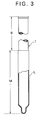
- Fig. 3 is an explanatory view like Fig. 2, showing the condition where a latex has adhered to the main body of the shaping mold of Fig. 2 in the condom-producing line of Fig. 1.
- Fig. 4 is an explanatory view like Fig. 2, showing the condition where a shaped condom has adhered to the surface of the main body of the shaping mold of Fig. 2 in the condom-producing line of Fig. 1.
- Fig. 5 is a partly-cut explanatory view of showing the shaping mold for production of condoms as formed in Example 2.
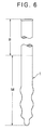
- Fig. 6 is a partly-cut explanatory view of showing the shaping mold for production of condoms as formed in Example 3.
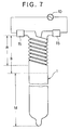
- Fig. 7 is a partly-cut explanatory view of showing the shaping mold for production of condoms as formed in Example 4.
- The present invention will be explained concretely hereunder, on the basis of the examples as illustrated in the drawings attached hereto.
- Fig. 1 shows a condom-producing line of one embodiment of the present invention. The condom-producing line is basically composed of an endless belt 2 on which a number of shaping
molds 1 for producing condoms of the present invention have been mounted, a washing tank 3 for washing the shapingmolds 1, alatex liquid tank 4 where the main bodies of the washed shapingmolds 1 are dipped in a latex liquid therein, apre-heating room 5 where the latex as adhered to the main bodies of the shapingmolds 1 is preliminarily heated and dried, a heat-drying room 6 where the shaped articles as pre-heated in thepre-heating room 5 are again heated and dried after the upper portion of each pre-heated shaped article has been rolled with fingers to form a reinforced part at the opening of the product to be a condom, anelectrolytic solution tank 7 where the condom as dried in the heat-drying room 6 and adhered to the surface of the main body of the shapingmold 1 is subjected to pin hole inspection, a product drying room 8 where the condoms as passed through theelectrolytic solution tank 7 is finally dried, and apeeling device 9 where the product condom is peeled from the shapingmold 1 with removing the condoms as judged to be defective ones when they have passed through theelectrolytic solution tank 7. - In the above-mentioned
pre-heating room 5 and heat-drying room 6, each shapingmold 1 is electrified so as to heat the heating area thereof by resistance heating in addition to the external heating to the molds whereby the latex or semi-dried latex as adhered to the surface of the shapingmolds 1 is heat-dried and cured. In the above-mentionedelectrolytic solution tank 7, a direct current voltage for pin hole inspection is applied between thecontact electrode 7a, which is kept in contact with the shapingmold 1, and theelectrode 7b, which has been disposed in the electrolytic solution. Accordingly, while the shapingmolds 1 pass through the electrolytic solution in theelectrolytic solution tank 7, an electric current flows therethrough via pin hole(s), if any, of the condom as adhered to the main body of the shapingmold 1 so that the condom is detected to be a defective one as having pin hole(s). Thetank 7 is so constituted that the information derived from the detection is transmitted to thepeeling device 9 so as to remove the defective condoms. - The body of the shaping
mold 1 as used in Example 1 is, as shown in Fig. 2, composed of the main body M which is dipped in a latex liquid in its use and the bottom part B which is above the main body M and is not dipped in a latex liquid. The main body M add the bottom part B are composed of thecore part 1b made of an isotropic graphite material and thesurface part 1a of an amorphous carbon as laminated over the surface of thepart 1b. The upper portion of the mold body is fitted with aheating electrode 11 which is to be connected to the alternatingcurrent heating source 10 when the shapingmold 1 is in thepre-heating room 5 and the heat-drying room 6 and also with a band-like electrode 12 made of an amorphous carbon with maintaining the heating area R from theheating electrode 11. The band-like electrode 12 made of an amorphous carbon is not only one electrode to be connected to the above-mentioned alternatingcurrent heating source 10 but also acts as a contact terminal which is brought into contact with thecontact electrode 7a of the directcurrent voltage source 13 for pin hole inspection of shaped condoms while the shapingmold 1 is passing through theelectrolytic solution tank 7, whereupon it short-circuits with theelectrode 7b as disposed in the electrolytic solution in theelectrolytic solution tank 7 when the shaped condom has some pin hole(s). - The main body M of the shaping
mold 1 of Example 1 is dipped in the latex liquid in thelatex liquid tank 4. After thelatex liquid tank 4, a determined amount of a latex L has adhered to the surface of the main body M to form a film of a determined thickness. Then, it is preliminarily heated and dried in thepre-heating room 5 and thereafter completely heated and dried in the heat-drying room 6, whilst the upper portion of the shaped film is rolled with fingers, as shown in Fig. 4, to form the reinforcedpart 14 at the opening of the shaped product condom C. - Next, the shaping molds for production of ultra-thin shaped rubber articles of the present invention, including the shaping
mold 1 as used in Example 1, and methods of forming them will be explained hereunder. - 54 g of a mixture (2,4-TDI/2,6-TDI = 80/20) of 2,4-tolylene diisocyanate (2,4-TDI) and 2,6-tolylene diisocyanate (2,6-TDI) were reacted at 120°C for 4 hours in 500 ml of tetrachloroethylene in the presence of 0.12 g of a carbodiimidating catalyst (1-phenyl-3-methylphospholene oxide) to obtain a polycarbodiimide solution.
- 50 g of methylenediphenyl diisocyanate (MDI) were reacted at 120°C for 6 hours in 820 ml of tetrachloroethylene in the presence of a carbodiimidating catalyst (1-phenyl-3-methylphospholene oxide), and the obtained reaction mixture was cooled to room temperature to precipitate the formed polycarbodiimide, which was then filtered. The precipitates thus obtained were dried at 100°C for 2 hours to obtain a polycarbodiimide powder.
- An isotropic graphite material (having a bulk density of 1.83 g/cm3 and a flexural strength of 500 kg/cm2) was worked into a shape of the
core part 1b of Fig. 2, and the polycarbodiimide solution as obtained in the above-mentioned Preparation Example 1 was coated over its surface by spray coating. Then, this was dried at 80°C for 3 hours, at 120°C for 4 hours and at 200°C for one hour. - The shaped body thus formed was heated in nitrogen gas from room temperature up to 1,000°C, 1,500°C, 2,000°C or 2,500°C each at a temperature-elevating rate of 10°C/min and was carbonized at the elevated temperature, whereby the
surface layer 1a of amorphous carbon was laminated over thecore part 1b. The thickness of thesurface layer 1a thus formed was from 1 to 3 µm. - The shaping
mold 1 thus formed was checked with respect to the wettability with a natural rubber latex liquid, the intrinsic resistivity value and the thermal conductivity. The results obtained are shown in Table 1 below. - The polycarbodiimide solution as obtained in Preparation Example 1 was concentrated with an evaporator to have a resin solid content of 50 % by weight. The thus obtained high-concentration polycarbodiimide solution was cast into a mold and heat-treated therein at 60°C for 20 hours, at 80°C for 20 hours and at 120°C for 20 hours. The shaped body was released from the mold to obtain a hollow-shaped polycarbodiimide resin body of Fig. 5.
- The shaped polycarbodiimide resin body was heated in nitrogen gas from room temperature up to 1,000°C, 1,500°C, 2,000°C or 2,500°C each at a temperature-elevating rate of 0.2°C/min and was carbonized at the elevated temperature. Thus, a
hollow shaping mold 1 wholly made of an amorphous carbon was formed, as shown in Fig. 5. - The shaping
mold 1 thus formed was checked with respect to the wettability with a natural rubber latex liquid, the intrinsic resistivity value and the thermal conductivity. The results obtained are shown in Table 1 below. - The polycarbodiimide powder as obtained in Preparation Example 2 was put in a mold and shaped under heat and pressure under the condition of 180°C and 80 kg/cm2, and this was cooled to room temperature and released from the mold to obtain a shaped polycarbodiimide resin body having the shape of Fig. 6.
- The surface of the shaped polycarbodiimide resin body was ground to mirror finish, and the body was carbonized under the same conditions as those in the above-mentioned Example 3 to give a shaping
mold 1 of Fig. 6. - The shaping
mold 1 thus formed was checked with respect to the wettability with a natural rubber latex liquid, the intrinsic resistivity value and the thermal conductivity. The results obtained are shown in Table 1 below. - Using a phenolic resin (BRL-274, produced by Showa Highpolymer Co.), a shaped phenolic resin body was formed under the same conditions as those in Example 3. This was carbonized under the same conditions as those in Example 3 to give a
hollow shaping mold 1 wholly made of an amorphous carbon, as shown in Fig. 5. - The shaping
mold 1 thus formed was checked with respect to the wettability with a natural rubber latex liquid, the intrinsic resistivity value and the thermal conductivity. The results obtained are shown in Table 1 below.Table 1 Example Carbonizing Temperature (°C) Evaluation of Wettability Intrinsic Resistivity (Ω.cm) Thermal Conductivity (cal/cm.sec.°C) 2 1,000 O 0.0006 0.3 1,500 O 0.0006 0.3 2,000 O 0.0006 0.3 2,500 O 0.0006 0.3 3 1,000 O 0.0051 0.010 1,500 O 0.0048 0.015 2,000 O 0.0046 0.020 2,500 O 0.0040 0.035 4 1,000 O 0.0052 0.010 1,500 O 0.0048 0.016 2,000 O 0.0048 0.022 2,500 O 0.0040 0.035 5 1,000 O 0.0050 0.010 1,500 O 0.0048 0.014 2,000 O 0.0046 0.021 2,500 O 0.0040 0.034 (Note) For the evaluation of the wettability, the mark "O" indicates that production of condoms with the mold is possible. - The polycarbodiimide powder as obtained in Preparation Example 2 was put in a mold and formed into a shaped polycarbodiimide resin body in the same manner as in Example 4. The bottom part B of the body was cut into the double-spiral form of Fig. 7, while the surface of the main body M of the shaped polycarbodiimide resin body was ground to mirror finish. This was carbonized under the same conditions as those in the above-mentioned Example 3 to give a shaping
mold 1 of Fig. 7. - Using the shaping
mold 1 of this example where the double-spiral area as formed in the bottom part B may be a heating area R having a higher electric resistance, more efficient resistance heating may be attained. In the shapingmold 1 of this example, 15 is an electrode of the alternatingcurrent heat source 10. - As is obvious from the results of the above-mentioned examples, when the shaping mold for production of ultra-thin shaped rubber articles is used in producing ultra-thin shaped rubber articles, the troublesome operation of "peeling a shaped article from the shaping mold followed by re-mounting it on a different inspecting mold for its inspection" in the inspecting step may be omitted and, additionally, the shaped article may be heat-dried from the inside of the shaping mold during the process of producing it, especially in the heat-drying step, so that formation of pin holes in the shaped articles may be prevented as much as possible. In addition, the shaping mold for production of ultra-thin shaped rubber articles is lightweight and is well workable to various shapes with ease. In particular, the surface of the mold is easily worked to mirror finish which is indispensable to a shaping mold for production of condoms.
- Moreover, since the method of producing ultra-thin shaped rubber articles uses the above-mentioned shaping molds, all the steps of constituting the method, including the inspecting step, may be carried out continuously with one shaping mold without interrupting the course of continuous production of ultra-thin shaped rubber articles. Accordingly, since not only the production efficiency of the method may be elevated but also formation of pin holes in the shaped articles to be produced by the method may be prevented as much as possible, the method is extremely useful for industrial use.
Claims (6)
- A shaping mold (1) for production of ultra-thin shaped rubber articles, the main body (M) of which mold is to be dipped in a latex liquid so as to make the latex adhere to the surface of the main body (M) with the adhered latex being heat-dried to form an ultra-thin shaped rubber article over the surface; the shaping mold (1) being characterized in that at least the surface (1a) of its main body (M) to be dipped in the latex liquid is made of an amorphous carbon, and in that its bottom part (B), which is not to be dipped in the latex liquid, is provided with electrifying electrodes (11,12) defining therebetween a heating area (R) to be heated by resistance heating due to its electrification.
- A shaping mold (1) for production of ultra-thin shaped rubber articles as claimed in claim 1, the core part (1b) of which mold (1) is made of a graphite material and is laminated with a surface layer (1a) of an amorphous carbon over its surface.
- A shaping mold (1) for production of ultra-thin shaped rubber articles as claimed in claim 1, which is wholly made of an amorphous carbon and which is hollow, having an open bottom part.
- A shaping mold (1) for production of ultra-thin shaped rubber articles as claimed in claim 1, in which the amorphous carbon to form at least the surface (1a) of the mold is formed by shaping a resin as selected from polycarbodiimides, phenolic resins, polyacrylonitriles, polyimides, polyvinyl chlorides, polyvinylidene chlorides and furan resins followed by carbonizing the shaped body.
- A method of producing ultra-thin shaped rubber articles, comprising:(a) a dipping step of successively dipping shaping molds (1) in a latex liquid so as to make the latex adhere to the surfaces of the shaping molds,(b) a heat-drying step, and(c) an inspecting step of directly dipping the shaped articles as shaped on the shaping molds in an electrolytic solution, without removing them from the molds, followed by electrifying the molds for effecting pin hole inspection of the shaped articles,characterised by using shaping molds (1) having at least the surface of their main body (M) to be dipped in the latex liquid made of an amorphous carbon and having their bottom part (B), which is not to be dipped in the latex liquid, provided with electrifying electrodes (11,12) defining therebetween a heating area (R) to be heated by resistance heating due to its electrification, and by electrifying in the heat-drying step the shaping molds (1) so as to heat their heating areas by resistance heating to thereby heat and dry the latex as adhered to the surfaces of the shaping molds.
- A method of producing ultra-thin shaped rubber articles as claimed in claim 5, in which the heat-drying of the latex as adhered to the surfaces of the shaping molds (1) in the heat-drying step is effected by external heating and also by the resistance heating due to the electrification of the molds.
Applications Claiming Priority (5)
| Application Number | Priority Date | Filing Date | Title |
|---|---|---|---|
| JP21007/92U | 1992-02-21 | ||
| JP2100792 | 1992-02-21 | ||
| JP8188092 | 1992-10-14 | ||
| JP81880/92U | 1992-10-14 | ||
| PCT/JP1993/000208 WO1993016857A1 (en) | 1992-02-21 | 1993-02-22 | Mold for manufacturing very thin rubber molding and method of manufacturing the mold |
Publications (3)
| Publication Number | Publication Date |
|---|---|
| EP0587903A1 EP0587903A1 (en) | 1994-03-23 |
| EP0587903A4 EP0587903A4 (en) | 1994-04-27 |
| EP0587903B1 true EP0587903B1 (en) | 1997-05-02 |
Family
ID=26358013
Family Applications (1)
| Application Number | Title | Priority Date | Filing Date |
|---|---|---|---|
| EP93904328A Expired - Lifetime EP0587903B1 (en) | 1992-02-21 | 1993-02-22 | Mold for manufacturing very thin rubber molding and method of manufacturing the mold |
Country Status (5)
| Country | Link |
|---|---|
| US (2) | US5595704A (en) |
| EP (1) | EP0587903B1 (en) |
| CA (1) | CA2108888A1 (en) |
| DE (1) | DE69310297T2 (en) |
| WO (1) | WO1993016857A1 (en) |
Families Citing this family (9)
| Publication number | Priority date | Publication date | Assignee | Title |
|---|---|---|---|---|
| DE4426225B4 (en) * | 1994-07-23 | 2005-08-04 | Robert Griebel | Device for checking the porosity of thin rubber products |
| JP3389775B2 (en) * | 1995-05-19 | 2003-03-24 | 株式会社デンソー | Insert product molding method and insert product molding device |
| US6217815B1 (en) * | 1998-06-10 | 2001-04-17 | Carter-Wallace, Inc. | Method and apparatus for manufacturing prophylactic devices |
| US7484224B2 (en) * | 2002-05-02 | 2009-01-27 | Bae Systems, Inc. | Adapter deployment without recycle |
| US6611149B1 (en) | 2002-12-23 | 2003-08-26 | Agri Dynamics, Inc. | Condom nipple testing apparatus |
| TW201446162A (en) * | 2013-03-19 | 2014-12-16 | Weng Kee Richard Boey | New dipping former for producing elastic articles |
| CN107405805A (en) * | 2015-03-18 | 2017-11-28 | 翁凯·理查德·梅 | For producing the Novel immersion rubber moulding of elastic article |
| US10974420B2 (en) | 2017-03-21 | 2021-04-13 | International Business Machines Corporation | Feature casting for manufacture observation |
| CN111267281A (en) * | 2020-01-20 | 2020-06-12 | 广州大明联合橡胶制品有限公司 | Intelligent condom production method and system |
Family Cites Families (25)
| Publication number | Priority date | Publication date | Assignee | Title |
|---|---|---|---|---|
| US2228992A (en) * | 1939-02-17 | 1941-01-14 | Dean Rubber Mfg Company | Method of producing beaded articles from liquid latex |
| US2867847A (en) * | 1953-04-22 | 1959-01-13 | Int Latex Corp | Forms for manufacture of deposited latex articles |
| US2893085A (en) * | 1954-03-20 | 1959-07-07 | Elek Ska Svetsningsaktiebolage | Methods of casting steel bodies |
| NL7200575A (en) * | 1971-01-28 | 1972-08-01 | ||
| US3850563A (en) * | 1973-03-16 | 1974-11-26 | T Milonas | System and method for confectionary molding |
| DE2358802A1 (en) * | 1973-11-26 | 1975-05-28 | Kraftwerk Union Ag | PROCEDURE FOR IDENTIFYING WALL DAMAGE INSIDE THE HEAT EXCHANGER TUBES |
| US4001359A (en) * | 1974-09-19 | 1977-01-04 | Allied Chemical Corporation | Testing and correcting metering accuracy of multihole spinnerets |
| SU549764A1 (en) * | 1975-12-29 | 1977-03-05 | Комплексная Геофизическая Экспедиция Научно-Производственного Объединения "Союзгеофизика" | Device for recording seismic vibrations |
| US4104343A (en) * | 1977-03-04 | 1978-08-01 | Monsanto Company | Detecting and sorting abnormal articles during blow molding |
| US4340348A (en) * | 1980-02-29 | 1982-07-20 | Bioresearch Inc. | Glove molding apparatus |
| IT1189758B (en) * | 1986-05-26 | 1988-02-04 | Fip Formatura Inienzione Poli | DEVICE FOR THE FORMING OF THERMOPLASTIC PRODUCTS EQUIPPED WITH UNDER TEAM |
| US5116551A (en) * | 1987-05-07 | 1992-05-26 | Davidson Roderick I | Method and apparatus for producing an article by microwave heating |
| GB8710833D0 (en) * | 1987-05-07 | 1987-06-10 | Porous Plastics Ltd | Microwave heating |
| JPS648012A (en) * | 1987-06-30 | 1989-01-12 | Meiki Seisakusho Kk | Nozzle structure of injection molding machine |
| JPH01108012A (en) * | 1987-10-22 | 1989-04-25 | Souzou Kagaku:Kk | Mold for item having opening at least at its end and to be closely in contact with any part of human body |
| SU1549764A1 (en) * | 1988-05-26 | 1990-03-15 | М.Ю. Бродский, О.В. Харламов, А.С. Малевский-Малевич, А.К. Евменов и Ю.Я. Левкин | Mould for making dipped articles |
| JPH0230507A (en) * | 1988-07-21 | 1990-01-31 | Souzou Kagaku:Kk | Molding tool for sticking product to body part |
| JP2725705B2 (en) * | 1988-12-02 | 1998-03-11 | 日清紡績株式会社 | Cell separator for fuel cells |
| US5176866A (en) * | 1989-02-28 | 1993-01-05 | Asahi Kasei Kogyo Kabushiki Kaisha | Process for producing a resin product having a bent hollow portion and a core usable for the same process |
| JPH0324750A (en) * | 1989-06-22 | 1991-02-01 | Nec Corp | Cap of package for semiconductor device |
| JPH03230507A (en) * | 1990-02-06 | 1991-10-14 | Taiyo Yuden Co Ltd | Manufacture of inductor element and its fitting method |
| US5246198A (en) * | 1990-06-01 | 1993-09-21 | Canon Kabushiki Kaisha | Diamond crystal coated mold for forming optical elements |
| US5336322A (en) * | 1992-03-06 | 1994-08-09 | Konica Corporation | Coating apparatus |
| US5323544A (en) * | 1993-01-22 | 1994-06-28 | Ansell Incorporated | Method and apparatus for drying coatings or films |
| JP2503888B2 (en) | 1993-06-30 | 1996-06-05 | 日本電気株式会社 | Data transmission method in mobile radio communication |
-
1993
- 1993-02-22 CA CA002108888A patent/CA2108888A1/en not_active Abandoned
- 1993-02-22 DE DE69310297T patent/DE69310297T2/en not_active Expired - Fee Related
- 1993-02-22 WO PCT/JP1993/000208 patent/WO1993016857A1/en active IP Right Grant
- 1993-02-22 US US08/133,128 patent/US5595704A/en not_active Expired - Fee Related
- 1993-02-22 EP EP93904328A patent/EP0587903B1/en not_active Expired - Lifetime
-
1996
- 1996-05-31 US US08/657,659 patent/US5667822A/en not_active Expired - Fee Related
Also Published As
| Publication number | Publication date |
|---|---|
| EP0587903A4 (en) | 1994-04-27 |
| DE69310297T2 (en) | 1997-11-20 |
| WO1993016857A1 (en) | 1993-09-02 |
| DE69310297D1 (en) | 1997-06-05 |
| US5667822A (en) | 1997-09-16 |
| US5595704A (en) | 1997-01-21 |
| EP0587903A1 (en) | 1994-03-23 |
| CA2108888A1 (en) | 1993-08-22 |
Similar Documents
| Publication | Publication Date | Title |
|---|---|---|
| EP0587903B1 (en) | Mold for manufacturing very thin rubber molding and method of manufacturing the mold | |
| US4614837A (en) | Method for placing electrically conductive paths on a substrate | |
| US3266661A (en) | Method of applying electro-conductive coatings and resulting article | |
| EP1139703B1 (en) | Substrate of circuit board | |
| JPH0426239B2 (en) | ||
| WO2005092587A1 (en) | Method of evaluating adherence, material of low adherence and resin shaping die | |
| JPH056433B2 (en) | ||
| US4189700A (en) | Resistor device | |
| KR100887126B1 (en) | Transfer member with electric conductivity and its manufacturing method | |
| US4189509A (en) | Resistor device and method of making | |
| US6395203B1 (en) | Process for producing low impurity level ceramic | |
| US3397125A (en) | Electrolytic processes | |
| EP0388899B1 (en) | A method for the formation of an electrolyte layer of solid electrolytic capacitors | |
| JPH10130055A (en) | Production of electrode plate for plasma treatment device | |
| JP3163143B2 (en) | Heat treatment substrate and method of manufacturing the same | |
| JP3136300B2 (en) | Conductive ceramics, method for producing conductive ceramics film, method for producing conductive ceramics molded product, composition for forming conductive ceramics, and electric heating element | |
| JP3890540B2 (en) | Metal-ceramic composite substrate and manufacturing method thereof | |
| JPS63297031A (en) | Method for repairing carbon fiber reinforced carbon composite material | |
| EP3615317A1 (en) | Mobile membrane press | |
| JP3707113B2 (en) | Method for producing polyimide tubular product | |
| JPH034513B2 (en) | ||
| KR101656817B1 (en) | Method for preparing graphite sheet and film roll structure used therein | |
| JPH11189471A (en) | Roll made of vitrified carbon, its production, plasma generator, its chamber inner wall protecting member, protection of the chamber inner wall and plasma treatment | |
| TWI239053B (en) | Wafer holder for semiconductor manufacturing device and semiconductor manufacturing device in which it is installed | |
| JPS63299303A (en) | Manufacture of circuit element |
Legal Events
| Date | Code | Title | Description |
|---|---|---|---|
| PUAI | Public reference made under article 153(3) epc to a published international application that has entered the european phase |
Free format text: ORIGINAL CODE: 0009012 |
|
| 17P | Request for examination filed |
Effective date: 19931119 |
|
| AK | Designated contracting states |
Kind code of ref document: A1 Designated state(s): DE FR GB |
|
| A4 | Supplementary search report drawn up and despatched |
Effective date: 19940309 |
|
| AK | Designated contracting states |
Kind code of ref document: A4 Designated state(s): DE FR GB |
|
| RAP1 | Party data changed (applicant data changed or rights of an application transferred) |
Owner name: NISSHINBO INDUSTRIES, INC. Owner name: SOHZOHKAGAKU CO., LTD. |
|
| 17Q | First examination report despatched |
Effective date: 19950912 |
|
| GRAG | Despatch of communication of intention to grant |
Free format text: ORIGINAL CODE: EPIDOS AGRA |
|
| GRAH | Despatch of communication of intention to grant a patent |
Free format text: ORIGINAL CODE: EPIDOS IGRA |
|
| GRAH | Despatch of communication of intention to grant a patent |
Free format text: ORIGINAL CODE: EPIDOS IGRA |
|
| GRAA | (expected) grant |
Free format text: ORIGINAL CODE: 0009210 |
|
| AK | Designated contracting states |
Kind code of ref document: B1 Designated state(s): DE FR GB |
|
| PG25 | Lapsed in a contracting state [announced via postgrant information from national office to epo] |
Ref country code: FR Free format text: THE PATENT HAS BEEN ANNULLED BY A DECISION OF A NATIONAL AUTHORITY Effective date: 19970502 |
|
| REF | Corresponds to: |
Ref document number: 69310297 Country of ref document: DE Date of ref document: 19970605 |
|
| ET | Fr: translation filed | ||
| PG25 | Lapsed in a contracting state [announced via postgrant information from national office to epo] |
Ref country code: GB Free format text: LAPSE BECAUSE OF NON-PAYMENT OF DUE FEES Effective date: 19980222 |
|
| PLBE | No opposition filed within time limit |
Free format text: ORIGINAL CODE: 0009261 |
|
| STAA | Information on the status of an ep patent application or granted ep patent |
Free format text: STATUS: NO OPPOSITION FILED WITHIN TIME LIMIT |
|
| 26N | No opposition filed | ||
| GBPC | Gb: european patent ceased through non-payment of renewal fee |
Effective date: 19980222 |
|
| PG25 | Lapsed in a contracting state [announced via postgrant information from national office to epo] |
Ref country code: DE Free format text: LAPSE BECAUSE OF NON-PAYMENT OF DUE FEES Effective date: 19981103 |
|
| REG | Reference to a national code |
Ref country code: FR Ref legal event code: ST |