EP0573204B1 - Network connection method - Google Patents
Network connection method Download PDFInfo
- Publication number
- EP0573204B1 EP0573204B1 EP93304075A EP93304075A EP0573204B1 EP 0573204 B1 EP0573204 B1 EP 0573204B1 EP 93304075 A EP93304075 A EP 93304075A EP 93304075 A EP93304075 A EP 93304075A EP 0573204 B1 EP0573204 B1 EP 0573204B1
- Authority
- EP
- European Patent Office
- Prior art keywords
- network
- transceiver
- mac
- sleep
- data
- Prior art date
- Legal status (The legal status is an assumption and is not a legal conclusion. Google has not performed a legal analysis and makes no representation as to the accuracy of the status listed.)
- Expired - Lifetime
Links
Images


Classifications
-
- G—PHYSICS
- G06—COMPUTING; CALCULATING OR COUNTING
- G06F—ELECTRIC DIGITAL DATA PROCESSING
- G06F1/00—Details not covered by groups G06F3/00 - G06F13/00 and G06F21/00
- G06F1/26—Power supply means, e.g. regulation thereof
- G06F1/32—Means for saving power
- G06F1/3203—Power management, i.e. event-based initiation of a power-saving mode
- G06F1/3206—Monitoring of events, devices or parameters that trigger a change in power modality
- G06F1/3215—Monitoring of peripheral devices
-
- H—ELECTRICITY
- H04—ELECTRIC COMMUNICATION TECHNIQUE
- H04L—TRANSMISSION OF DIGITAL INFORMATION, e.g. TELEGRAPHIC COMMUNICATION
- H04L43/00—Arrangements for monitoring or testing data switching networks
- H04L43/08—Monitoring or testing based on specific metrics, e.g. QoS, energy consumption or environmental parameters
- H04L43/0805—Monitoring or testing based on specific metrics, e.g. QoS, energy consumption or environmental parameters by checking availability
- H04L43/0811—Monitoring or testing based on specific metrics, e.g. QoS, energy consumption or environmental parameters by checking availability by checking connectivity
-
- H—ELECTRICITY
- H04—ELECTRIC COMMUNICATION TECHNIQUE
- H04L—TRANSMISSION OF DIGITAL INFORMATION, e.g. TELEGRAPHIC COMMUNICATION
- H04L12/00—Data switching networks
- H04L12/02—Details
- H04L12/10—Current supply arrangements
-
- H—ELECTRICITY
- H04—ELECTRIC COMMUNICATION TECHNIQUE
- H04L—TRANSMISSION OF DIGITAL INFORMATION, e.g. TELEGRAPHIC COMMUNICATION
- H04L12/00—Data switching networks
- H04L12/02—Details
- H04L12/12—Arrangements for remote connection or disconnection of substations or of equipment thereof
-
- H—ELECTRICITY
- H04—ELECTRIC COMMUNICATION TECHNIQUE
- H04L—TRANSMISSION OF DIGITAL INFORMATION, e.g. TELEGRAPHIC COMMUNICATION
- H04L12/00—Data switching networks
- H04L12/28—Data switching networks characterised by path configuration, e.g. LAN [Local Area Networks] or WAN [Wide Area Networks]
- H04L12/44—Star or tree networks
-
- Y—GENERAL TAGGING OF NEW TECHNOLOGICAL DEVELOPMENTS; GENERAL TAGGING OF CROSS-SECTIONAL TECHNOLOGIES SPANNING OVER SEVERAL SECTIONS OF THE IPC; TECHNICAL SUBJECTS COVERED BY FORMER USPC CROSS-REFERENCE ART COLLECTIONS [XRACs] AND DIGESTS
- Y02—TECHNOLOGIES OR APPLICATIONS FOR MITIGATION OR ADAPTATION AGAINST CLIMATE CHANGE
- Y02D—CLIMATE CHANGE MITIGATION TECHNOLOGIES IN INFORMATION AND COMMUNICATION TECHNOLOGIES [ICT], I.E. INFORMATION AND COMMUNICATION TECHNOLOGIES AIMING AT THE REDUCTION OF THEIR OWN ENERGY USE
- Y02D30/00—Reducing energy consumption in communication networks
- Y02D30/50—Reducing energy consumption in communication networks in wire-line communication networks, e.g. low power modes or reduced link rate
Definitions
- the present invention relates generally to a method for automatic connection and disconnection of a node in a local area network (LAN) to manage power of a LAN controller, and particularly, it relates to such a method as implemented with an Ethernet network employing a transmitter/receiver (transceiver) which meets the ANSI/IEEE 802.3 10BASE-T international standard.
- a transmitter/receiver transmitter/receiver
- it relates to such a method implemented a media access controller (MAC) for 802.3/Ethernet, also known as MACE, implemented in an integrated circuit including the 10BASE-T transceiver.
- MAC media access controller
- Ethernet is a commonly used local area network scheme in which multiple stations are connected to a single shared serial data path. Typically, only one station can transmit data onto the path at a time. A station connected to the path transmits data in the form of a packet that includes a destination address. The packet propagates throughout the network medium and is received by all other stations. The addressed station copies the entire packet as it goes by; the others reject the packet after determining that it is addressed to another station.
- a Media Access Controller serves as an interface between a shared data path and the stations connected to that path.
- Each node connected to the network includes a MAC which performs a number of functions involved in the transmission and reception of data packets. For example, during the transmission of data, the MAC assembles the data to be transmitted into a packet with address and error detection fields. Conversely, during the reception of a packet, the MAC disassembles the packet and performs address checking and error detection. In addition, the MAC typically performs encoding/decoding of digital signals transmitted over the shared path and performs preamble generation/removal as well as bit transmission/reception.
- the coaxial cable provides a linear bus to which all nodes are connected. Signalling is accomplished using a current sink technique with the center conductor used for signal, and the shield as a ground reference.
- Twisted pair Ethernet in accordance with IEEE Standard 802.3 IOBASE-T is able to use standard voice grade telephone cable employing separate transmit and receive pairs (4 wires).
- the system uses a star topology. At the center of the star is a "repeater”.
- the repeater (or hub) performs signal amplitude and timing restoration. It takes an incoming bit stream and repeats it to all other ports connected to it (but not back to the originating port). In this sense, the repeater acts as "logical coax", so that any node connected to the network will see another's transmission. Differential signalling is employed with one pair acting as the transmit path, and the other as receive. Further details on IOBASE-T Ethernet networks, including a description of the state of the art for such networks, is provided by Crayford, "10BASE-T in the Office,” Wescon, San Francisco, November 20, 1991.
- Transceivers as used in 10BASE-T Ethernet networks may incorporate a sleep mode, in which a node incorporating the transceiver powers down when there is no activity for it after a predetermined period of time.
- a node incorporating the transceiver powers down when there is no activity for it after a predetermined period of time.
- it will miss any transmissions intended for it. It would be desirable to provide the power saving advantages of the sleep mode without resulting in missed transmissions.
- Efficient network management also requires that nodes on a network be identified as present. With prior art sleep modes, a network controller of a node in sleep mode is treated as if it were disconnected from the network.
- a method for operating a local area network which comprises connecting a data processing terminal to an Ethernet local area network through an Ethernet media access controller and an Ethernet 10 Base-T transceiver and comprising periodically signalling the presence of the network to the transceiver, the method being characterised by the steps of:
- US-A-4,996,706 discloses a data communication interface for exchanging data between a computer station and a telephone system.
- the interface comprises the computer station and a bidirectional modem with an associated data access means including a ringing detection circuit and a control unit.
- the interface provides for an energy saving "stand-by" mode in which the modem is powered down during times in which no data transmission or reception activity occurs.
- the ringing detection circuit detects a calling signal on the telephone line from a remote computer station and initiates powering up of the modem by the control unit. Similarly, the powering up of the modem can be triggered by a transmission request signal from the computer station.
- WO-A-92,03004 discloses a power controlled local computer connected to a telephone line, the power controlling being responsive to a carrier detect signal on the telephone line.
- EP-A-0,343,630 discloses a data communication system in which data processing terminals are linked via a transmission line to a master station which sends out commands using an address portion within a data frame to designate the destination terminal.
- the terminal can receive a reset signal in the same manner as normal data and, upon receipt of that reset signal, initiate a reset instruction. This indicates that the terminal must be awake and in normal receive operation in order to receive the reset signal which is sent and received in the same manner as a normal data signal.
- This disclosure does not involve a sleep mode.
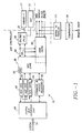
- Figure 1 is a block diagram of a media access controller incorporating the invention for an Ethernet network.
- Figure 2 is a more detailed block diagram of a portion of the media access controller incorporating the invention, connected in a network.
- Figure 3 is a block diagram corresponding to Figure 2 of an alternative embodiment of the invention, connected in a network.
- Figure 4 is a diagram showing control bit assignments for practice of the invention.
- Figures 5A and 5B are a more detailed block diagram of a portion of the media access controller of Figure 1.
- the MAC 30 controls the passage of information between a shared Ethernet serial data path 32 and a system bus 34.
- the MAC 30 includes a Manchester encoder/decoder 36 and a MAC core 38, which in the preferred embodiment, is implemented in accordance with the IEEE 802.3 standard.
- the MAC 30 also includes a receive FIFO 40, a transmit FIFO 42 and FIFO control logic 44 as well as command and control registers 46.
- a system bus interface unit 48 is logically disposed between the receive and transmit FIFOs 40 and 42 and the system bus 34.
- the MAC core 38 includes a station address detect (SAD) unit 50 which determines whether packets received by the MAC 30 in fact are addressed to it and should be captured in their entirety, or are addressed to a different MAC station (not shown) and should be rejected.
- SAD station address detect
- the byte tracking system of this invention is incorporated in the system bus interface unit 48, transmit FIFO 42, MAC core 38 and Manchester encoder/decoder 36 of the MAC 30.
- the encoder/decoder 36 is connected to an Attachment Unit Interface (AUI) transceiver 35 and a 10BASE-T transceiver 37. Further background information on the Ethernet data processing network and the MAC 30 are provided in EP-A-0,558,234.
- the 10BASE-T transceiver 37 outputs a link beat pulse 60 every 8-24 milliseconds. Detection of the link beat pulses 60 produced by the transceiver 37 by the transceiver 37a is used to establish that a link in the network is in place.
- Figure 3 shows a portion of another embodiment of a network system in which 10BASE-T transceivers 37' and 37a' each output a link beat pulse 60 every 8-24 milliseconds. Detection of the link beat pulses 60 produced by the other transceiver to which the transceivers 37' and 37a' are connected is used to establish that a link in the network is in place.
- the "AUTO WAKE” (AWAKE) feature of the MAC 30 is specifically designed for use with mobile computing equipment, such as laptop or palmtop computers.
- the "REMOTE WAKE” (RWAKE) feature is intended for use in secure environments, providing a remote manager the capability of enabling or disabling a LAN station remotely, using a network command.
- One of the fundamental benefits of the 10BASE-T physical interface for 802.3/Ethernet of Figure 2 is that the health of the communications link can be permanently monitored. This is known as the Link Integrity Test.
- the 10BASE-T transceiver 37 When in the "link good” condition, the 10BASE-T transceiver 37 is required to output a link status (LNKST) signal to this effect.
- a SLEEP pin (not shown) on the MAC 30 is an input that allows the MAC 30 to be placed in one of its power saving modes. When SLEEP is active, all outputs will be placed in an inactive or high impedance state, providing that both the AWAKE bit and the RWAKE bit functions in a PHY Configuration Control register (not shown) are not enabled. This is the optimal mode for power saving, allowing clock inputs to the MAC 30 to be suspended. If the AWAKE bit is set prior to the activation of SLEEP, the 10BASE-T receiver 37 and the LNKST output pin remain operational.
- the Manchester encoder/decoder 36, AUI cell and 10BASE-T cell 37 remain operational, as do the SRD, SRDCLK and SF/BD outputs.
- the input on XTALI must remain active for the AWAKE or RWAKE features to operate.
- the receive section of the 10-BASE T transceiver 37 can remain powered, even if the SLEEP input to the MAC 30 is activated. This allows the transceiver 37 to detect a link beat pulse 60 or receive packet activity. If either receive condition is encountered, the internal transceiver 37 will activate the LNKST output from the MAC 30.
- the system hardware and/or software can use the LNKST output to take appropriate action. For instance, if the LNKST output is active (low), then the computer is connected to an active network, and it is likely that the operating system will allow the MAC 30 to remain powered.
- the system can assume that the link is inactive, and the MAC can be powered down to save power. If at a later time the link is re-established, the MAC 3() can be powered back up to take advantage of the communications channel. In this way, the power consumption of the Ethernet connection can be managed by the operating software/hardware.
- the receive section of the 10BASE-T transceiver 37 and AUI port remain powered after the SLEEP input to the MAC 30 is activated.
- External Address Detection Interface (EADI) 52 is maintained operational. This allows data received on either the AUI or 10BASE-T receiver 37 to be passed to the EADI 52, via the Manchester decoder 36, and hence allows an external address or message detection circuit to observe the contents of the incoming packet. In this way, a system can be simply designed to provide a central manager station with the ability to control remotely the state of the MAC 30 and the associated computer station.
- EADI External Address Detection Interface
- External circuitry can be implemented to interface to pins of the EADI 52, and effectively wait for a match based on a specific receive frame contents, in addition to just address alone.
- a serial to parallel converter 53 and a comparator 55 of a terminal to which the MAC 30 is connected are shown.
- the comparator 55 provides a remote wake signal in response to a command from the central manager to reawaken from a sleep mode. This mode of operation effectively allows the MAC 30 and associated external logic to respond to specific frames on the network and thereby facilitate remote controlled node operation.
- the EADI 52 of the MAC 30 offers a unique solution. Not only can the station be remotely powered down, but with segregated power supply distribution, the MAC 30 and the associated EADI logic can remain active, and effectively wait for a command to reactivate the station. This function is referred to as the "Remote Wake" capability.
- the end station can implement security as simply as disabling the keyboard entry and/or display system, or a more sophisticated power down of all non-critical functions, such as the system CPU itself.
- the AWAKE and RWAKE bits are located in the PHY Configuration Control (PHYCC) register of the MAC 30. All bits within the PHY Configuration Control register are cleared by hardware or software reset. Bit assignments are as shown in Figure 4. Each bit has the function described in the following table:
- FIGs 5A and 5B Further details of the MAC 30 as shown in Figure 1 are provided in Figures 5A and 5B. These diagrams are useful for understanding operation of the AUI and 10BASE-T circuits 35 and 37, and their interaction with the SLEEP pin and AWAKE/RWAKE bits.
- the MAC core cell 38 performs all of the 802.3/Ethernet transmit and frame assembly and interfaces through the bus interface unit 48 to the host system bus 34.
- Port multiplexer 80 allows the MAC 30 to select between the AUI interface 35 and the 10BASE-T interface 37.
- the port selection process as such is not a part of the present invention and is therefore not described in detail, but it basically allows either manual selection (via programmable bits) or automatic selection (using the LNKST pin indication) of the media interface.
- Manchester encoder 82 and phase locked loop (PLL) and decoder 84 together form the Manchester encoder/decoder 36.
- transmit data flow originates from the MAC 38, which is Manchester encoded at 82 and then passed to the appropriate AUI or 10BASE-T media driver 86 or 88 through transmit logic 87 or 89.
- Receive data flow may originate from either the AUI or the 10BASE-T receiver 90 or 92.
- the receivers 90 and 92 first perform pulse amplitude detection. If the received waveform passes the amplitude criteria, pulse width detection is then performed at 94 or 96. In the case of the AUI, if pulse amplitude and width criteria are met, the signal is effectively qualified and passed to receive multiplexer 98 as AUI receive data and AUI receive carrier sense signals.
- the AUI waveform is also received and amplitude tested by collision detection receiver 91 and tested for pulse width at 95. If the AUI waveform meets the amplitude and width criteria, an AUI collision signal is supplied to the port multiplexer to block AUI transmissions while an AUI waveform is being received. For the 10BASE-T receive path, data is further qualified by "smart squelch" 100, which in essence looks for multiple pulses in a specific order, to ascertain that this receive waveform is packet data and not noise. If the waveform passes this criteria, it is qualified and passed to the receive multiplexer 98 as 10BASE-T data and 10BASE-T receive carrier sense.
- the receive multiplexer 98 is set up to select one of the receive data paths (either by programming or automatically as previously discussed), allowing the receive data to be decoded from Manchester to non-return to zero (NRZ) format by the PLL/decoder 84, and passed to the MAC 38 through the port multiplexer 80.
- NRZ non-return to zero
- link test pulses 60 ( Figure 3) on line 101 is controlled by 10BASE-T transmit link state machine 102, so that pulses are transmitted during periods of data (packet) inactivity.
- 10BASE-T receive link state machine 104 monitors the presence of receive link beat pulses or packet data, and asserts the LNKST pin if the link is considered operable.
- SLEEP 1 and SLEEP 2 outputs from port multiplexer 80 are effectively set up by the condition of the AWAKE and RWAKE bits. If the SLEEP pin is activated, and AWAKE and RWAKE have not been programmed, SLEEP 1 and SLEEP 2 will be activated, shutting down the AUI and 10BASE-T transmit and receive functions. Note that 10BASE-T link test pulses will not be generated by the MAC 30 when the SLEEP pin is asserted, as an additional power saving feature. Note also that the entire MAC core portion 38 of the chip will be in a low power sleep mode, consuming minimal power.
- SLEEP 1 is asserted, but SLEEP 2 is not. This powers down the entire AUI transmit and receive paths, and the 10BASE-T transmit path. However, the 10BASE-T receiver 92 remains powered, and the receive chain remains operable, including the ability to detect link test pulses.
- SLEEP 1 and SLEEP 2 are " not asserted. Both the AUI and IOBASE-T receivers 90 and 92 remain operable, as does the PLL/decoder 84. Data received will be passed to the port multiplexer 80, which will allow the EADI 52 output pins Serial Receive Data (SRD), Serial Receive Data Clock (SRDCLK) and Start Frame/Byte Delimiter (SF/BD) to be driven.
- SRD Serial Receive Data
- SRDCLK Serial Receive Data Clock
- SF/BD Start Frame/Byte Delimiter
- the transmit portions of the AUI and IOBASE-T interfaces will not be in their most optimal power conservation mode, but will be static (no data and/or link test pulses will be transmitted).
- the MAC core 38 will of course be in its power saving mode.
- the LNKST pin output buffer is active when in the normal operating mode or when AWAKE is set before SLEEP is asserted (it is not active during RWAKE operation).
- the data processing network controller operates in a sleep mode to conserve power, but a portion of the controller remains active to monitor for transmissions. Power consumption of a network connection is managed by operating software/hardware.
- a data processing network controller can be used to power down a terminal on a network from a central network system, and the terminal can also be powered up from the central network system. A portion of the network controller remains active to signal its presence to the network during the sleep mode.
Landscapes
- Engineering & Computer Science (AREA)
- Computer Networks & Wireless Communication (AREA)
- Signal Processing (AREA)
- Theoretical Computer Science (AREA)
- Environmental & Geological Engineering (AREA)
- Physics & Mathematics (AREA)
- General Engineering & Computer Science (AREA)
- General Physics & Mathematics (AREA)
- Small-Scale Networks (AREA)
- Computer And Data Communications (AREA)
Description
- The present invention relates generally to a method for automatic connection and disconnection of a node in a local area network (LAN) to manage power of a LAN controller, and particularly, it relates to such a method as implemented with an Ethernet network employing a transmitter/receiver (transceiver) which meets the ANSI/IEEE 802.3 10BASE-T international standard. Preferably, it relates to such a method implemented a media access controller (MAC) for 802.3/Ethernet, also known as MACE, implemented in an integrated circuit including the 10BASE-T transceiver.
- Ethernet is a commonly used local area network scheme in which multiple stations are connected to a single shared serial data path. Typically, only one station can transmit data onto the path at a time. A station connected to the path transmits data in the form of a packet that includes a destination address. The packet propagates throughout the network medium and is received by all other stations. The addressed station copies the entire packet as it goes by; the others reject the packet after determining that it is addressed to another station.
- A Media Access Controller (MAC) serves as an interface between a shared data path and the stations connected to that path. Each node connected to the network includes a MAC which performs a number of functions involved in the transmission and reception of data packets. For example, during the transmission of data, the MAC assembles the data to be transmitted into a packet with address and error detection fields. Conversely, during the reception of a packet, the MAC disassembles the packet and performs address checking and error detection. In addition, the MAC typically performs encoding/decoding of digital signals transmitted over the shared path and performs preamble generation/removal as well as bit transmission/reception.
- Traditional Ethernet is a coaxial wired system. The coaxial cable provides a linear bus to which all nodes are connected. Signalling is accomplished using a current sink technique with the center conductor used for signal, and the shield as a ground reference.
- Twisted pair Ethernet in accordance with IEEE Standard 802.3 IOBASE-T is able to use standard voice grade telephone cable employing separate transmit and receive pairs (4 wires). The system uses a star topology. At the center of the star is a "repeater". The repeater (or hub) performs signal amplitude and timing restoration. It takes an incoming bit stream and repeats it to all other ports connected to it (but not back to the originating port). In this sense, the repeater acts as "logical coax", so that any node connected to the network will see another's transmission. Differential signalling is employed with one pair acting as the transmit path, and the other as receive. Further details on IOBASE-T Ethernet networks, including a description of the state of the art for such networks, is provided by Crayford, "10BASE-T in the Office," Wescon, San Francisco, November 20, 1991.
- Transceivers as used in 10BASE-T Ethernet networks may incorporate a sleep mode, in which a node incorporating the transceiver powers down when there is no activity for it after a predetermined period of time. However, when the node is in the sleep mode, it will miss any transmissions intended for it. It would be desirable to provide the power saving advantages of the sleep mode without resulting in missed transmissions. Efficient network management also requires that nodes on a network be identified as present. With prior art sleep modes, a network controller of a node in sleep mode is treated as if it were disconnected from the network.
- According to the present invention there is provided a method for operating a local area network, which comprises connecting a data processing terminal to an Ethernet local area network through an Ethernet media access controller and an Ethernet 10 Base-T transceiver and comprising periodically signalling the presence of the network to the transceiver, the method being characterised by the steps of:
- allowing the media access controller to assume a power saving sleep mode while allowing a receive section of the transceiver to remain awake;
- signalling the presence of the network to said receive section of the transceiver when the media access controller is in the sleep mode; and
- awakening the media access controller from the sleep mode in response to said transceiver receiving from the network a packet transmission including a node address for the data processing terminal and an awakening instruction.
-
- Before proceeding to a detailed description of the present invention, three prior art documents cited in EP-A3-0,573,204 will be acknowledged as follows.
- US-A-4,996,706 discloses a data communication interface for exchanging data between a computer station and a telephone system. The interface comprises the computer station and a bidirectional modem with an associated data access means including a ringing detection circuit and a control unit. The interface provides for an energy saving "stand-by" mode in which the modem is powered down during times in which no data transmission or reception activity occurs. The ringing detection circuit detects a calling signal on the telephone line from a remote computer station and initiates powering up of the modem by the control unit. Similarly, the powering up of the modem can be triggered by a transmission request signal from the computer station.
- WO-A-92,03004 discloses a power controlled local computer connected to a telephone line, the power controlling being responsive to a carrier detect signal on the telephone line.
- EP-A-0,343,630 discloses a data communication system in which data processing terminals are linked via a transmission line to a master station which sends out commands using an address portion within a data frame to designate the destination terminal. The terminal can receive a reset signal in the same manner as normal data and, upon receipt of that reset signal, initiate a reset instruction. This indicates that the terminal must be awake and in normal receive operation in order to receive the reset signal which is sent and received in the same manner as a normal data signal. This disclosure does not involve a sleep mode.
- Figure 1 is a block diagram of a media access controller incorporating the invention for an Ethernet network.
- Figure 2 is a more detailed block diagram of a portion of the media access controller incorporating the invention, connected in a network.
- Figure 3 is a block diagram corresponding to Figure 2 of an alternative embodiment of the invention, connected in a network.
- Figure 4 is a diagram showing control bit assignments for practice of the invention.
- Figures 5A and 5B are a more detailed block diagram of a portion of the media access controller of Figure 1.
- Turning now to the drawings, more particularly to Figure 1, there is shown a media access controller (MAC) 30 used as an interface in an Ethernet data processing network. The MAC 30 controls the passage of information between a shared Ethernet
serial data path 32 and asystem bus 34. The MAC 30 includes a Manchester encoder/decoder 36 and aMAC core 38, which in the preferred embodiment, is implemented in accordance with the IEEE 802.3 standard. The MAC 30 also includes a receive FIFO 40, a transmit FIFO 42 and FIFOcontrol logic 44 as well as command andcontrol registers 46. A systembus interface unit 48 is logically disposed between the receive and transmitFIFOs system bus 34. TheMAC core 38 includes a station address detect (SAD)unit 50 which determines whether packets received by theMAC 30 in fact are addressed to it and should be captured in their entirety, or are addressed to a different MAC station (not shown) and should be rejected. The byte tracking system of this invention is incorporated in the systembus interface unit 48, transmit FIFO 42,MAC core 38 and Manchester encoder/decoder 36 of theMAC 30. The encoder/decoder 36 is connected to an Attachment Unit Interface (AUI)transceiver 35 and a 10BASE-T transceiver 37. Further background information on the Ethernet data processing network and theMAC 30 are provided in EP-A-0,558,234. - Further details on the IOBASE-
T transceiver 37, its connection to theMAC 30 and its connection to another IOBASE-T transceiver 37a are shown in Figure 2. In operation, the 10BASE-T transceiver 37 outputs alink beat pulse 60 every 8-24 milliseconds. Detection of thelink beat pulses 60 produced by thetransceiver 37 by thetransceiver 37a is used to establish that a link in the network is in place. - Figure 3 shows a portion of another embodiment of a network system in which 10BASE-T transceivers 37' and 37a' each output a
link beat pulse 60 every 8-24 milliseconds. Detection of thelink beat pulses 60 produced by the other transceiver to which thetransceivers 37' and 37a' are connected is used to establish that a link in the network is in place. - The "AUTO WAKE" (AWAKE) feature of the MAC 30 is specifically designed for use with mobile computing equipment, such as laptop or palmtop computers. The "REMOTE WAKE" (RWAKE) feature is intended for use in secure environments, providing a remote manager the capability of enabling or disabling a LAN station remotely, using a network command.
- One of the fundamental benefits of the 10BASE-T physical interface for 802.3/Ethernet of Figure 2 is that the health of the communications link can be permanently monitored. This is known as the Link Integrity Test. When in the "link good" condition, the 10BASE-
T transceiver 37 is required to output a link status (LNKST) signal to this effect. TheMAC 30, with the embedded 10BASE-T transceiver 37, uses the LNKST signal to provide power management to theMAC 30. - A SLEEP pin (not shown) on the
MAC 30 is an input that allows theMAC 30 to be placed in one of its power saving modes. When SLEEP is active, all outputs will be placed in an inactive or high impedance state, providing that both the AWAKE bit and the RWAKE bit functions in a PHY Configuration Control register (not shown) are not enabled. This is the optimal mode for power saving, allowing clock inputs to theMAC 30 to be suspended. If the AWAKE bit is set prior to the activation of SLEEP, the 10BASE-T receiver 37 and the LNKST output pin remain operational. If the RWAKE bit is set prior to SLEEP being asserted, the Manchester encoder/decoder 36, AUI cell and 10BASE-T cell 37 remain operational, as do the SRD, SRDCLK and SF/BD outputs. The input on XTALI must remain active for the AWAKE or RWAKE features to operate. - By using the programmable AWAKE bit, the receive section of the 10-
BASE T transceiver 37 can remain powered, even if the SLEEP input to theMAC 30 is activated. This allows thetransceiver 37 to detect alink beat pulse 60 or receive packet activity. If either receive condition is encountered, theinternal transceiver 37 will activate the LNKST output from theMAC 30. The system hardware and/or software can use the LNKST output to take appropriate action. For instance, if the LNKST output is active (low), then the computer is connected to an active network, and it is likely that the operating system will allow theMAC 30 to remain powered. However, if the LNKST becomes inactive (high) then the system can assume that the link is inactive, and the MAC can be powered down to save power. If at a later time the link is re-established, the MAC 3() can be powered back up to take advantage of the communications channel. In this way, the power consumption of the Ethernet connection can be managed by the operating software/hardware. - By using the programmable RWAKE bit, the receive section of the 10BASE-
T transceiver 37 and AUI port remain powered after the SLEEP input to theMAC 30 is activated. In addition, External Address Detection Interface (EADI) 52 is maintained operational. This allows data received on either the AUI or 10BASE-T receiver 37 to be passed to theEADI 52, via theManchester decoder 36, and hence allows an external address or message detection circuit to observe the contents of the incoming packet. In this way, a system can be simply designed to provide a central manager station with the ability to control remotely the state of theMAC 30 and the associated computer station. - External circuitry can be implemented to interface to pins of the
EADI 52, and effectively wait for a match based on a specific receive frame contents, in addition to just address alone. By way of example, a serial toparallel converter 53 and acomparator 55 of a terminal to which theMAC 30 is connected are shown. Thecomparator 55 provides a remote wake signal in response to a command from the central manager to reawaken from a sleep mode. This mode of operation effectively allows theMAC 30 and associated external logic to respond to specific frames on the network and thereby facilitate remote controlled node operation. - Some emerging network management protocols, such as the 3Com/lBM HLM Specification, already have the requirement to be able to control the node remotely. For applications requiring network controlled power or security management, the
EADI 52 of theMAC 30 offers a unique solution. Not only can the station be remotely powered down, but with segregated power supply distribution, theMAC 30 and the associated EADI logic can remain active, and effectively wait for a command to reactivate the station. This function is referred to as the "Remote Wake" capability. Since the logic for "snooping" on the receive packet, and the power management distribution, is under the control of the system designer, the end station can implement security as simply as disabling the keyboard entry and/or display system, or a more sophisticated power down of all non-critical functions, such as the system CPU itself. - The AWAKE and RWAKE bits are located in the PHY Configuration Control (PHYCC) register of the
MAC 30. All bits within the PHY Configuration Control register are cleared by hardware or software reset. Bit assignments are as shown in Figure 4. Each bit has the function described in the following table: - Bit 7 LNKFL
- LNKFL reports the link integrity of the IOBASE-T receiver.
When the link test function is enabled (DLNKTST = 0), the
absence of link beat pulses on the Receive Data (RXD)± pair
will cause the integrated 10BASE-
T transceiver 37 to go into the link fail state. In the link fail state, data transmission, data reception, data loopback and the collision detection functions are disabled, and remain disabled until valid data or >5 consecutive link pulses appear on the RXD± pair. During link fail, the LNKST pin is internally pulled HIGH. When the link is identified as functional, the LNKST pin is driven LOW, and is capable of directly driving a "Link OK" LED. In order to inter-operate with systems which do not implement Link Test, this function can be disabled by setting the DLNKTST biL With Link Test disabled (DLNKTST = 1), the data driver, receiver and loopback functions as well as collision detection remain enabled irrespective of the presence or absence of data or link pulses on the RXD± pair. The transmitter will continue to generate link beat pulses during periods of transmit data inactivity. - Bit 6 DLNKTST
- Disable Link Test. When set, the integrated IOBASE-
T transceiver 37 will be forced into the link pass state, regardless of receive link test pulses or receive packet activity. - Bit 5 REVPOL
- Reversed Polarity. Indicates the receive polarity of the RXD± pair. When normal polarity is detected, the REVPOL bit will be cleared, and the RXPOL pin (capable of driving a "Polarity OK" LED) will be driven low. When reverse polarity is detected, the REVPOL bit will be set, and the RXPOL pin should be externally pulled high.
- Bit 4 DAPC
- Disable Auto Polarity Correction. When set, the automatic polarity correction will be disabled. Polarity detection and indication will still be possible via the RXPOL pin.
- Bit 3 LTS
- Low Threshold Select. When set, the threshold of the twisted pair receiver will be reduced by 4.5 dB, to allow extended distance operation.
-
Bit 2 ASEL - Auto Select. When set, the PORTSEL [1-0] bits are
overridden, and the
MAC 30 will automatically select the operating media interface port. When the 10BASE-T transceiver is in the link pass state (due to receiving valid packet data and/or Link Test pulses or the DLNKTST bit is set), the 10BASE-T port will be used. When the 10BASE-T port is in the link fail state, the AUI port will be used. Switching between the ports will not occur during transmission, to avoid any type of fragment generation. -
Bit 1 RWAKE - Remote Wake. When set prior to the SLEEP pin being
activated, the AUI and 10BASE-T receiver sections and the
EADI 52 will continue to operate even during SLEEP. Incoming packet activity will be passed to theEADI 52 pins to allow detection of specific frame contents to be used to initiate removal of the SLEEP function. RWAKE must be programmed prior to SLEEP being asserted for this function to operate. RWAKE is not cleared by SLEEP, only by activation of the SWRST bit or RESET pin. - Bit 0 AWAKE
- Auto Wake. When set prior to the SLEEP pin being activated, the 10BASE-T receiver section will continue to operate even during SLEEP, and will activate the LNKST pin if receive activity is detected. AWAKE must be programmed prior to SLEEP being asserted for this function to operate. AWAKE is not cleared by SLEEP, only by activation of the SWRST bit or RESET pin.
- Further details of the
MAC 30 as shown in Figure 1 are provided in Figures 5A and 5B. These diagrams are useful for understanding operation of the AUI and 10BASE-T circuits MAC core cell 38 performs all of the 802.3/Ethernet transmit and frame assembly and interfaces through thebus interface unit 48 to thehost system bus 34.Port multiplexer 80 allows theMAC 30 to select between theAUI interface 35 and the 10BASE-T interface 37. The port selection process as such is not a part of the present invention and is therefore not described in detail, but it basically allows either manual selection (via programmable bits) or automatic selection (using the LNKST pin indication) of the media interface.Manchester encoder 82 and phase locked loop (PLL) anddecoder 84 together form the Manchester encoder/decoder 36. - Assuming normal (SLEEP inactive) operation, transmit data flow originates from the
MAC 38, which is Manchester encoded at 82 and then passed to the appropriate AUI or 10BASE-T media driver logic T receiver receivers multiplexer 98 as AUI receive data and AUI receive carrier sense signals. Similarly, the AUI waveform is also received and amplitude tested bycollision detection receiver 91 and tested for pulse width at 95. If the AUI waveform meets the amplitude and width criteria, an AUI collision signal is supplied to the port multiplexer to block AUI transmissions while an AUI waveform is being received. For the 10BASE-T receive path, data is further qualified by "smart squelch" 100, which in essence looks for multiple pulses in a specific order, to ascertain that this receive waveform is packet data and not noise. If the waveform passes this criteria, it is qualified and passed to the receivemultiplexer 98 as 10BASE-T data and 10BASE-T receive carrier sense. The receivemultiplexer 98 is set up to select one of the receive data paths (either by programming or automatically as previously discussed), allowing the receive data to be decoded from Manchester to non-return to zero (NRZ) format by the PLL/decoder 84, and passed to theMAC 38 through theport multiplexer 80. - In addition, for the 10BASE-T port, the transmission of link test pulses 60 (Figure 3) on
line 101 is controlled by 10BASE-T transmit link state machine 102, so that pulses are transmitted during periods of data (packet) inactivity. 10BASE-T receivelink state machine 104 monitors the presence of receive link beat pulses or packet data, and asserts the LNKST pin if the link is considered operable. -
SLEEP 1 andSLEEP 2 outputs fromport multiplexer 80 are effectively set up by the condition of the AWAKE and RWAKE bits. If the SLEEP pin is activated, and AWAKE and RWAKE have not been programmed,SLEEP 1 andSLEEP 2 will be activated, shutting down the AUI and 10BASE-T transmit and receive functions. Note that 10BASE-T link test pulses will not be generated by theMAC 30 when the SLEEP pin is asserted, as an additional power saving feature. Note also that the entireMAC core portion 38 of the chip will be in a low power sleep mode, consuming minimal power. - If AWAKE is set and the SLEEP pin activated,
SLEEP 1 is asserted, butSLEEP 2 is not. This powers down the entire AUI transmit and receive paths, and the 10BASE-T transmit path. However, the 10BASE-T receiver 92 remains powered, and the receive chain remains operable, including the ability to detect link test pulses. - If RWAKE is set and the SLEEP pin activated,
SLEEP 1 andSLEEP 2 are " not asserted. Both the AUI and IOBASE-T receivers decoder 84. Data received will be passed to theport multiplexer 80, which will allow the EADI 52 output pins Serial Receive Data (SRD), Serial Receive Data Clock (SRDCLK) and Start Frame/Byte Delimiter (SF/BD) to be driven. The transmit portions of the AUI and IOBASE-T interfaces will not be in their most optimal power conservation mode, but will be static (no data and/or link test pulses will be transmitted). TheMAC core 38 will of course be in its power saving mode. Since this mode is intended for "security" applications, the power conservation issue is not deemed as important. Note that the LNKST pin output buffer is active when in the normal operating mode or when AWAKE is set before SLEEP is asserted (it is not active during RWAKE operation). - The data processing network controller operates in a sleep mode to conserve power, but a portion of the controller remains active to monitor for transmissions. Power consumption of a network connection is managed by operating software/hardware. A data processing network controller can be used to power down a terminal on a network from a central network system, and the terminal can also be powered up from the central network system. A portion of the network controller remains active to signal its presence to the network during the sleep mode.
- It should further be apparent to those skilled in the art that various changes in form and details of the invention as shown and described may be made.
Claims (3)
- A method for operating a local area network, which comprises connecting a data processing terminal (34) to an Ethernet local area network through an Ethernet media access controller (MAC) (30) and an Ethernet 10 Base-T transceiver (37), and comprising periodically signalling the presence of the network to the transceiver, the method being characterised by the steps of:while the media access controller assumes a power saving sleep mode, a receive section of the transceiver remains awake;signalling the presence of the network to said receive section of the transceiver (37) when the media access controller is in the sleep mode; andawakening the media access controller from the sleep mode in response to said transceiver receiving from the network a packet transmission including a node address for the data processing terminal and an awakening instruction.
- The method of claim 1 additionally comprising the step of periodically signalling the network with the transceiver to signal presence of the transceiver on the network.
- The method of claim 1 or claim 2 comprising the step of monitoring the packet transmissions on the network by the transceiver.
Applications Claiming Priority (2)
| Application Number | Priority Date | Filing Date | Title |
|---|---|---|---|
| US894016 | 1992-06-05 | ||
| US07/894,016 US5404544A (en) | 1992-06-05 | 1992-06-05 | System for periodically transmitting signal to/from sleeping node identifying its existence to a network and awakening the sleeping node responding to received instruction |
Publications (3)
| Publication Number | Publication Date |
|---|---|
| EP0573204A2 EP0573204A2 (en) | 1993-12-08 |
| EP0573204A3 EP0573204A3 (en) | 1994-09-21 |
| EP0573204B1 true EP0573204B1 (en) | 2001-02-28 |
Family
ID=25402485
Family Applications (1)
| Application Number | Title | Priority Date | Filing Date |
|---|---|---|---|
| EP93304075A Expired - Lifetime EP0573204B1 (en) | 1992-06-05 | 1993-05-26 | Network connection method |
Country Status (5)
| Country | Link |
|---|---|
| US (1) | US5404544A (en) |
| EP (1) | EP0573204B1 (en) |
| JP (1) | JP3429806B2 (en) |
| KR (1) | KR940001611A (en) |
| DE (1) | DE69329958T2 (en) |
Cited By (2)
| Publication number | Priority date | Publication date | Assignee | Title |
|---|---|---|---|---|
| US6827088B2 (en) | 1998-09-29 | 2004-12-07 | Sharper Image Corporation | Ion emitting brush |
| CN100481800C (en) * | 1996-08-26 | 2009-04-22 | 索尼株式会社 | Electronic apparatus and operation mode controlling method therefor |
Families Citing this family (134)
| Publication number | Priority date | Publication date | Assignee | Title |
|---|---|---|---|---|
| US6359872B1 (en) * | 1997-10-28 | 2002-03-19 | Intermec Ip Corp. | Wireless personal local area network |
| US5381414A (en) * | 1993-11-05 | 1995-01-10 | Advanced Micro Devices, Inc. | Method and apparatus for determining if a data packet is addressed to a computer within a network |
| AU1974795A (en) | 1994-03-03 | 1995-09-18 | Proxim, Inc. | Frequency hopping medium access control protocol |
| US6292508B1 (en) | 1994-03-03 | 2001-09-18 | Proxim, Inc. | Method and apparatus for managing power in a frequency hopping medium access control protocol |
| JP3258812B2 (en) * | 1994-04-20 | 2002-02-18 | 富士通株式会社 | Power supply with power saving function |
| US6175556B1 (en) * | 1994-06-06 | 2001-01-16 | International Business Machines Corporation | Remote powered ethernet repeater |
| US6000003A (en) | 1994-09-29 | 1999-12-07 | Maxim Integrated Products, Inc. | Communication circuit having network connection detection capability |
| US5799194A (en) * | 1994-09-29 | 1998-08-25 | Maxim Integrated Products | Communication interface circuit having network connection detection capability |
| JP3629521B2 (en) * | 1994-10-20 | 2005-03-16 | アドバンスト・マイクロ・ディバイシズ・インコーポレイテッド | System and method for remote wake-up |
| US5835719A (en) * | 1994-10-20 | 1998-11-10 | Advanced Micro Devices, Inc. | Apparatus and method for remote wake-up in system having interlinked networks |
| KR970010634B1 (en) * | 1994-10-25 | 1997-06-28 | 삼성전자 주식회사 | Metwork hibernation system |
| US5675800A (en) * | 1994-11-30 | 1997-10-07 | Digital Equipment Corporation | Method and apparatus for remotely booting a computer system |
| JP2669367B2 (en) * | 1994-12-07 | 1997-10-27 | 日本電気株式会社 | LAN adapter |
| FI97659C (en) * | 1995-01-13 | 1997-01-27 | Nokia Mobile Phones Ltd | Method and apparatus for saving power during infrared data transmission |
| JP3617105B2 (en) * | 1995-02-16 | 2005-02-02 | ソニー株式会社 | Electronic device and operation mode control method thereof |
| US5832296A (en) * | 1995-04-26 | 1998-11-03 | Interval Research Corp. | Wearable context sensitive user interface for interacting with plurality of electronic devices of interest to the user |
| US5726650A (en) * | 1995-06-07 | 1998-03-10 | Silicon Systems, Inc. | Adaptive manchester decoding with adjustable delay and power saving mode |
| JP3434934B2 (en) * | 1995-06-07 | 2003-08-11 | 株式会社デンソー | Wireless vehicle control system |
| US5809313A (en) * | 1995-07-06 | 1998-09-15 | Sun Microsystems, Inc. | Method and apparatus for powering-on a computer-based system via a network interface |
| DE19531373C1 (en) * | 1995-08-25 | 1996-12-05 | Siemens Nixdorf Inf Syst | Mode switching method for personal computer modem link |
| JP3463433B2 (en) * | 1995-11-07 | 2003-11-05 | 株式会社デンソー | Multiplex communication system |
| US5742833A (en) * | 1995-11-30 | 1998-04-21 | International Business Machines Corporation | Programmable power management system and method for network computer stations |
| GB2308469A (en) * | 1995-12-22 | 1997-06-25 | Motorola Inc | Power conserving clocking system |
| US5652895A (en) * | 1995-12-26 | 1997-07-29 | Intel Corporation | Computer system having a power conservation mode and utilizing a bus arbiter device which is operable to control the power conservation mode |
| US6678712B1 (en) | 1996-01-19 | 2004-01-13 | International Business Machines Corporation | Method and system for executing a program under one of a plurality of mutually exclusive operating environments |
| DE19608776C2 (en) * | 1996-03-07 | 2003-03-20 | Atmel Germany Gmbh | Integrated circuit arrangement with a bus logic unit connected to a data bus |
| US5884041A (en) * | 1996-03-13 | 1999-03-16 | Ics Technologies, Inc. | Method and apparatus for monitoring auto-negotiation progress |
| US5862391A (en) * | 1996-04-03 | 1999-01-19 | General Electric Company | Power management control system |
| US5802305A (en) * | 1996-05-17 | 1998-09-01 | Microsoft Corporation | System for remotely waking a sleeping computer in power down state by comparing incoming packet to the list of packets storing on network interface card |
| US5809118A (en) * | 1996-05-30 | 1998-09-15 | Softell | System and method for triggering actions at a host computer by telephone |
| MY121267A (en) | 1996-09-05 | 2006-01-28 | Sony Corp | Digital recording apparatus and copyright protection method thereof |
| JP3941178B2 (en) | 1996-09-05 | 2007-07-04 | ソニー株式会社 | Recording medium, digital recording device, and control IC |
| US7221853B1 (en) | 1996-09-05 | 2007-05-22 | Sony Corporation | Digital recording apparatus and copyright protection method thereof |
| US5915119A (en) * | 1996-10-01 | 1999-06-22 | Ncr Corporation | Proxy terminal for network controlling of power managed user terminals in suspend mode |
| US7383549B1 (en) * | 1997-01-08 | 2008-06-03 | Broadcom Corporation | Processor sharing technique for communications and other data processing on a same processor |
| US5983353A (en) * | 1997-01-21 | 1999-11-09 | Dell Usa, L.P. | System and method for activating a deactivated device by standardized messaging in a network |
| US6085248A (en) * | 1997-02-11 | 2000-07-04 | Xaqtu Corporation | Media access control transmitter and parallel network management system |
| US6108713A (en) * | 1997-02-11 | 2000-08-22 | Xaqti Corporation | Media access control architectures and network management systems |
| US6076115A (en) * | 1997-02-11 | 2000-06-13 | Xaqti Corporation | Media access control receiver and network management system |
| JP3870983B2 (en) | 1997-02-17 | 2007-01-24 | ソニー株式会社 | Electronic device control apparatus and method, and electronic device |
| US5826015A (en) * | 1997-02-20 | 1998-10-20 | Digital Equipment Corporation | Method and apparatus for secure remote programming of firmware and configurations of a computer over a network |
| US6101608A (en) * | 1997-02-20 | 2000-08-08 | Compaq Computer Corporation | Method and apparatus for secure remote wake-up of a computer over a network |
| US5919264A (en) * | 1997-03-03 | 1999-07-06 | Microsoft Corporation | System and method for using data structures to share a plurality of power resources among a plurality of devices |
| US6012150A (en) * | 1997-03-27 | 2000-01-04 | International Business Machines Corporation | Apparatus for synchronizing operator initiated commands with a failover process in a distributed processing system |
| US5860001A (en) * | 1997-05-19 | 1999-01-12 | International Business Machines Corporation | Computer system having at least two boot sequences |
| JP4367971B2 (en) | 1997-06-05 | 2009-11-18 | ソニー株式会社 | Electronic device control apparatus, electronic device control method, and electronic device |
| US5991806A (en) * | 1997-06-09 | 1999-11-23 | Dell Usa, L.P. | Dynamic system control via messaging in a network management system |
| JP3306651B2 (en) * | 1997-07-07 | 2002-07-24 | 吉田 富貴子 | Remote power switching equipment |
| JP3959159B2 (en) * | 1997-09-04 | 2007-08-15 | インターナショナル・ビジネス・マシーンズ・コーポレーション | Information processing system expansion unit, information processing system mounted on the expansion unit, and information processing system control method |
| US6047378A (en) * | 1997-09-29 | 2000-04-04 | International Business Machines Corporation | Wake multiple over LAN |
| US5945915A (en) * | 1997-11-06 | 1999-08-31 | International Business Machines Corporation | Computer system for sending an alert signal over a network when a cover of said system has been opened |
| US6021493A (en) * | 1997-11-06 | 2000-02-01 | International Business Machines Corporation | System and method for detecting when a computer system is removed from a network |
| US6026492A (en) * | 1997-11-06 | 2000-02-15 | International Business Machines Corporation | Computer system and method to disable same when network cable is removed |
| US6112247A (en) * | 1997-11-18 | 2000-08-29 | Intel Corporation | Network controller for processing status queries |
| JP3946330B2 (en) * | 1997-12-19 | 2007-07-18 | シャープ株式会社 | Data processing system |
| US6308278B1 (en) * | 1997-12-29 | 2001-10-23 | Intel Corporation | Supplying standby voltage to memory and wakeup circuitry to wake a computer from a low power mode |
| US6131167A (en) * | 1997-12-31 | 2000-10-10 | Intel Corporation | Method and apparatus to reduce power consumption on a bus |
| US6134665A (en) * | 1998-01-20 | 2000-10-17 | Digital Equipment Corporation | Computer with remote wake up and transmission of a status packet when the computer fails a self test |
| US6266696B1 (en) * | 1998-02-17 | 2001-07-24 | International Business Machine Corporation | Full time network auxiliary for a network connected PC |
| US6189108B1 (en) * | 1998-02-19 | 2001-02-13 | International Business Machine Corporation | Reporting of power states for a network connected PC |
| US6339792B1 (en) | 1998-02-27 | 2002-01-15 | International Business Machines Corporation | Dual two byte process for fast wake-up-on LAN frame detection |
| DE19809726A1 (en) * | 1998-03-06 | 1999-09-09 | Sgs Thomson Microelectronics | Interface for a data node of a data network |
| US6065122A (en) * | 1998-03-13 | 2000-05-16 | Compaq Computer Corporation | Smart battery power management in a computer system |
| WO1999053627A1 (en) | 1998-04-10 | 1999-10-21 | Chrimar Systems, Inc. Doing Business As Cms Technologies | System for communicating with electronic equipment on a network |
| US6158020A (en) * | 1998-04-14 | 2000-12-05 | International Business Machines Corporation | Remote jumper set and reset |
| US6026494A (en) * | 1998-04-21 | 2000-02-15 | Xircom, Inc. | Algorithm to reduce power consumption of an auto-negotiating ethernet transceiver |
| US6938040B2 (en) | 1998-04-28 | 2005-08-30 | International Business Machines Corporation | Pattern matching in communications network where first memory stores set of patterns, and second memory stores mask data identifying patterns in the first memory |
| US6098100A (en) * | 1998-06-08 | 2000-08-01 | Silicon Integrated Systems Corp. | Method and apparatus for detecting a wake packet issued by a network device to a sleeping node |
| US6889095B1 (en) * | 1998-06-11 | 2005-05-03 | Agilent Technologies, Inc. | Computer network adapted for industrial environments |
| US6292467B1 (en) | 1998-06-19 | 2001-09-18 | Advanced Micro Devices, Inc. | Apparatus and method of determining a link status between network stations connected to a telephone line medium |
| TW498206B (en) | 1998-07-28 | 2002-08-11 | Silicon Integrated Sys Corp | Method and device for matching data stream with a fixed pattern |
| US6353854B1 (en) * | 1998-10-01 | 2002-03-05 | International Business Machines Corporation | Automatic reconfiguration system for change in management servers having protocol destination addresses |
| US7079571B1 (en) * | 1998-10-08 | 2006-07-18 | Broadcom Corporation | Method and circuits for power management in a transceiver |
| AU1397000A (en) | 1998-11-30 | 2000-06-19 | International Business Machines Corporation | Data processing system and method for remotely disabling network activity in a client computer system |
| US6334147B1 (en) * | 1998-11-30 | 2001-12-25 | International Business Machines Corporation | Data processing system and method for remotely accessing a client computer systems's individual initialization settings while the client is powered off |
| US6763060B1 (en) * | 1999-02-19 | 2004-07-13 | Oasis Silicon Systems | Communication system employing a network of power managed transceivers that can generate a clocking signal or enable data bypass of a digital system associated with each transceiver |
| JP2000261482A (en) | 1999-03-08 | 2000-09-22 | Sony Corp | Address setting method, client device, server and client server system |
| JP3773688B2 (en) * | 1999-03-10 | 2006-05-10 | 株式会社リコー | Devices that can be connected to the network |
| JP3792066B2 (en) * | 1999-03-31 | 2006-06-28 | シャープ株式会社 | Low power consumption peripherals |
| JP4147689B2 (en) | 1999-06-14 | 2008-09-10 | ソニー株式会社 | Information processing apparatus and information processing method |
| JP2001066986A (en) | 1999-08-26 | 2001-03-16 | Sony Corp | Transmitter and method, receiver and method, communication system, and program storage medium |
| JP2001077831A (en) | 1999-09-08 | 2001-03-23 | Sony Corp | Communication controller, method, communication system and program storage medium |
| US6728892B1 (en) * | 1999-09-15 | 2004-04-27 | Koninklijke Philips Electronics N.V. | Method for conserving power in a can microcontroller and a can microcontroller that implements this method |
| JP4168304B2 (en) | 1999-09-16 | 2008-10-22 | ソニー株式会社 | Information output device, information notification method, and information signal supply route selection method |
| US6519697B1 (en) | 1999-11-15 | 2003-02-11 | Ncr Corporation | Method and apparatus for coordinating the configuration of massively parallel systems |
| US6412002B1 (en) | 1999-11-15 | 2002-06-25 | Ncr Corporation | Method and apparatus for selecting nodes in configuring massively parallel systems |
| US6745240B1 (en) | 1999-11-15 | 2004-06-01 | Ncr Corporation | Method and apparatus for configuring massively parallel systems |
| US6418526B1 (en) * | 1999-11-15 | 2002-07-09 | Ncr Corporation | Method and apparatus for synchronizing nodes in massively parallel systems |
| US6513128B1 (en) * | 1999-11-30 | 2003-01-28 | 3Com Corporation | Network interface card accessible during low power consumption mode |
| US6678728B1 (en) * | 1999-12-03 | 2004-01-13 | 3Com Corporation | Method and apparatus for automatically loading device status information into a network device |
| US7577958B1 (en) * | 1999-12-09 | 2009-08-18 | Nortel Networks Limited | Expediting an operation in a computer system |
| AU2275001A (en) * | 1999-12-20 | 2001-07-03 | Mitel Semiconductor V.N. Inc. | Power saving for mac ethernet control logic |
| GB2357601B (en) * | 1999-12-23 | 2004-03-31 | Ibm | Remote power control |
| US6529521B1 (en) * | 1999-12-27 | 2003-03-04 | Emc Corporation | Data storage system |
| US7127624B2 (en) | 2000-06-22 | 2006-10-24 | Broadcom Corporation | Energy detect with auto pair select |
| FR2810833B1 (en) * | 2000-06-27 | 2002-09-20 | Thomson Multimedia Sa | MULTIMEDIA AUDIOVISUAL TRANSMISSION RECEIVING APPARATUS |
| WO2002015476A2 (en) * | 2000-08-11 | 2002-02-21 | Broadcom Corporation | Energy detect with auto pair select |
| US6795450B1 (en) | 2000-09-28 | 2004-09-21 | Tdk Semiconductor Corporation | Method and apparatus for supporting physical layer link-suspend operation between network nodes |
| TW595152B (en) * | 2000-11-30 | 2004-06-21 | Winbond Electronics Corp | Control device and method of physical layer signal to generate a specific alarm data selectively |
| US8122271B1 (en) | 2000-12-14 | 2012-02-21 | Cisco Technology, Inc. | System, method, and device for providing secure operating environments for computer systems |
| US6993667B1 (en) | 2000-12-15 | 2006-01-31 | Marvell International Ltd. | Apparatus for automatic energy savings mode for ethernet transceivers and method thereof |
| US20030226050A1 (en) * | 2000-12-18 | 2003-12-04 | Yik James Ching-Shau | Power saving for mac ethernet control logic |
| US7493391B2 (en) * | 2001-02-12 | 2009-02-17 | International Business Machines Corporation | System for automated session resource clean-up by determining whether server resources have been held by client longer than preset thresholds |
| US7289449B1 (en) | 2001-03-20 | 2007-10-30 | 3Com Corporation | Device and method for managing fault detection and fault isolation in voice and data networks |
| US7283481B2 (en) | 2002-03-21 | 2007-10-16 | Broadcom Corporation | Auto detection of copper and fiber mode |
| US7362797B2 (en) | 2002-03-21 | 2008-04-22 | Broadcom Corporation | Physical layer device having an analog SERDES pass through mode |
| US7334068B2 (en) | 2002-07-26 | 2008-02-19 | Broadcom Corporation | Physical layer device having a SERDES pass through mode |
| US7787387B2 (en) | 2002-03-21 | 2010-08-31 | Broadcom Corporation | Auto-selection of SGMII or SerDes pass-through modes |
| US6685334B2 (en) | 2002-04-30 | 2004-02-03 | G-5 Electronics | System and method of power management for a solar powered device |
| US7477662B2 (en) * | 2003-02-14 | 2009-01-13 | Infineon Technologies Ag | Reducing power consumption in data switches |
| JP4133459B2 (en) * | 2003-03-06 | 2008-08-13 | シャープ株式会社 | Concentrator, network compatible device, communication system |
| CN100378617C (en) * | 2003-09-09 | 2008-04-02 | 华宇电脑股份有限公司 | Network wakening device and method |
| US7631086B2 (en) * | 2003-09-30 | 2009-12-08 | Onlex Technologies, Inc. | Virtual dedicated connection system and method |
| US7831282B2 (en) * | 2003-10-15 | 2010-11-09 | Eaton Corporation | Wireless node providing improved battery power consumption and system employing the same |
| JP4475099B2 (en) * | 2004-11-04 | 2010-06-09 | 富士ゼロックス株式会社 | Image forming apparatus and operation screen display control program |
| CN101101502A (en) * | 2006-07-07 | 2008-01-09 | 华硕电脑股份有限公司 | Network control device and network chip starting method |
| US7894351B2 (en) | 2006-11-20 | 2011-02-22 | International Business Machines Corporation | Detection of link status in blade systems |
| US8345673B1 (en) * | 2007-01-24 | 2013-01-01 | Marvell International, Ltd. | Physical-layer device (PHY) having a serial interface and a magic packet circuit |
| US8185767B2 (en) * | 2008-06-27 | 2012-05-22 | Microsoft Corporation | Automatic management of a power state of a device with network connections |
| US8219835B1 (en) * | 2008-08-27 | 2012-07-10 | Lockheed Martin Corporation | Power conservation in a data communication network |
| US8095815B2 (en) * | 2008-10-14 | 2012-01-10 | Hewlett-Packard Development Company, L.P. | System for reducing power consumption in an electronic chip |
| US8930534B2 (en) * | 2009-07-24 | 2015-01-06 | Broadcom Corporation | Method and system for management based end-to-end sleep limitation in an energy efficient ethernet network |
| US8850250B2 (en) | 2010-06-01 | 2014-09-30 | Intel Corporation | Integration of processor and input/output hub |
| US8782456B2 (en) * | 2010-06-01 | 2014-07-15 | Intel Corporation | Dynamic and idle power reduction sequence using recombinant clock and power gating |
| TWI448889B (en) * | 2010-08-27 | 2014-08-11 | Htc Corp | Electronic device haning operation mode dynamic adjusting mechanism and method of the same |
| US8762760B2 (en) | 2010-09-14 | 2014-06-24 | Xilinx, Inc. | Method and apparatus for adaptive power control in a multi-lane communication channel |
| US9146610B2 (en) | 2010-09-25 | 2015-09-29 | Intel Corporation | Throttling integrated link |
| US9455840B2 (en) * | 2011-05-02 | 2016-09-27 | Sony Corporation | Enhanced method for controlling network devices in a very low power consumption state |
| US9117036B2 (en) | 2012-09-26 | 2015-08-25 | Ati Technologies Ulc | Fast exit from low-power state for bus protocol compatible device |
| JP5775101B2 (en) * | 2013-01-18 | 2015-09-09 | 日本電信電話株式会社 | Signal receiving circuit |
| KR102089512B1 (en) * | 2013-11-05 | 2020-03-16 | 한국전자통신연구원 | Network Available Terminal's Sleep State Providing System and the Method |
| AU2017313154A1 (en) * | 2016-08-18 | 2019-03-21 | Niagara Bottling, Llc | Variable speed cryogen dosing system |
| US10116686B1 (en) * | 2017-10-16 | 2018-10-30 | Gideon Eden | Systems and methods for selectively insulating a processor |
| US11671911B2 (en) * | 2019-11-27 | 2023-06-06 | Andrew Wireless Systems Gmbh | Sleep-mode for ethernet controller |
Family Cites Families (13)
| Publication number | Priority date | Publication date | Assignee | Title |
|---|---|---|---|---|
| US4598275A (en) * | 1983-05-09 | 1986-07-01 | Marc Industries Incorporated | Movement monitor |
| US4698748A (en) * | 1983-10-07 | 1987-10-06 | Essex Group, Inc. | Power-conserving control system for turning-off the power and the clocking for data transactions upon certain system inactivity |
| GB8408538D0 (en) * | 1984-04-03 | 1984-05-16 | Senelco Ltd | Transmitter-responder systems |
| US4875158A (en) * | 1985-08-14 | 1989-10-17 | Apple Computer, Inc. | Method for requesting service by a device which generates a service request signal successively until it is serviced |
| KR900005796B1 (en) * | 1986-12-02 | 1990-08-11 | 삼성전자 주식회사 | Method for controlling the power supply of modem |
| US4903016A (en) * | 1987-07-07 | 1990-02-20 | Ricoh Company, Ltd. | Communication control unit |
| FR2626998B1 (en) * | 1988-02-05 | 1990-08-03 | Bendix Electronics Sa | OPERATIONAL AND STANDBY SYSTEM FOR ELECTRONIC BOXES CONNECTED TO A COMMUNICATION CHANNEL |
| JPH01298455A (en) * | 1988-05-27 | 1989-12-01 | Fujitsu Ltd | Communication terminal device |
| US5196728A (en) * | 1989-12-19 | 1993-03-23 | Jaeger | Method of controlling a network of electronic stations including a sleep mode when no active function is activated |
| WO1992003004A1 (en) * | 1990-07-30 | 1992-02-20 | Pulizzi Engineering, Inc. | Modem-controlled ac power controller |
| JP3143123B2 (en) * | 1990-11-06 | 2001-03-07 | マイクロン・テクノロジー・インコーポレイテッド | Dual mode electronic identification system |
| US5255306A (en) * | 1991-01-10 | 1993-10-19 | Bi Inc. | Cellular interface unit for use with an electronic house arrest monitoring system |
| US5182746A (en) * | 1991-03-28 | 1993-01-26 | Intel Corporation | Transceiver interface |
-
1992
- 1992-06-05 US US07/894,016 patent/US5404544A/en not_active Expired - Lifetime
-
1993
- 1993-05-26 EP EP93304075A patent/EP0573204B1/en not_active Expired - Lifetime
- 1993-05-26 DE DE69329958T patent/DE69329958T2/en not_active Expired - Lifetime
- 1993-06-02 JP JP13183593A patent/JP3429806B2/en not_active Expired - Lifetime
- 1993-06-05 KR KR1019930010160A patent/KR940001611A/en not_active Application Discontinuation
Non-Patent Citations (1)
| Title |
|---|
| '10Base-T in the Office', Ian Crayford, p. 232-237, 20.11.1991 * |
Cited By (2)
| Publication number | Priority date | Publication date | Assignee | Title |
|---|---|---|---|---|
| CN100481800C (en) * | 1996-08-26 | 2009-04-22 | 索尼株式会社 | Electronic apparatus and operation mode controlling method therefor |
| US6827088B2 (en) | 1998-09-29 | 2004-12-07 | Sharper Image Corporation | Ion emitting brush |
Also Published As
| Publication number | Publication date |
|---|---|
| DE69329958D1 (en) | 2001-04-05 |
| KR940001611A (en) | 1994-01-11 |
| EP0573204A3 (en) | 1994-09-21 |
| DE69329958T2 (en) | 2001-09-27 |
| JPH0637765A (en) | 1994-02-10 |
| US5404544A (en) | 1995-04-04 |
| JP3429806B2 (en) | 2003-07-28 |
| EP0573204A2 (en) | 1993-12-08 |
Similar Documents
| Publication | Publication Date | Title |
|---|---|---|
| EP0573204B1 (en) | Network connection method | |
| US9883457B2 (en) | Method and apparatus for reducing power consumption of a communications device during periods in which the communications device receives idle frames from another communications device | |
| EP1168717B1 (en) | Method and apparatus for regulating transceiver power consumption in a communications network | |
| US5825755A (en) | Method and apparatus for switching between full-duplex and half-duplex CSMA/CD systems | |
| US8276013B2 (en) | System and method for reducing a link failure detection delay using a link energy signal while in a low power idle mode | |
| US5936442A (en) | Power shut-off and recovery circuit for data communication devices | |
| US7036031B2 (en) | Electronic device and its power control method | |
| US9042363B2 (en) | Standby mode for use in a device having a multiple channel physical layer | |
| EP1080402B1 (en) | Power reduction algorithm for ethernet transceiver | |
| JP3871569B2 (en) | Network control system, network device, repeater, and connection device | |
| EP2224311B1 (en) | System and method for energy savings through emulation of wake on lan in energy efficient ethernet | |
| US5353353A (en) | Repeater security system | |
| US8595531B2 (en) | Energy efficient ethernet network nodes and methods for use in ethernet network nodes | |
| US5726976A (en) | Congestion sense controlled access for a star configured network | |
| EP1484876A2 (en) | Full duplex flow control for ethernet networks | |
| US6366143B1 (en) | Power shut-off and recovery circuit for data communication devices | |
| EP0939511A2 (en) | Method and arrangement in a network repeater for automatically changing link speed | |
| US6222854B1 (en) | Link monitor state machine | |
| EP0616449B1 (en) | Port activity monitor for an integrated multiport repeater | |
| US6600755B1 (en) | Link technology detection in multiple speed physical links | |
| US6834085B1 (en) | Low power signal detection for autonegotiation | |
| EP0480598A1 (en) | Repeater method and apparatus | |
| US20030058841A1 (en) | Anti-offline device adapted to be used in home PNA compliant network system and the data packet transmission method thereof | |
| JPH0991067A (en) | Interface | |
| JPH0756986B2 (en) | Loop network bypass method |
Legal Events
| Date | Code | Title | Description |
|---|---|---|---|
| PUAI | Public reference made under article 153(3) epc to a published international application that has entered the european phase |
Free format text: ORIGINAL CODE: 0009012 |
|
| AK | Designated contracting states |
Kind code of ref document: A2 Designated state(s): BE DE DK ES FR GB GR IE IT LU NL PT |
|
| PUAL | Search report despatched |
Free format text: ORIGINAL CODE: 0009013 |
|
| AK | Designated contracting states |
Kind code of ref document: A3 Designated state(s): BE DE DK ES FR GB GR IE IT LU NL PT |
|
| 17P | Request for examination filed |
Effective date: 19941222 |
|
| 17Q | First examination report despatched |
Effective date: 19970909 |
|
| RTI1 | Title (correction) |
Free format text: NETWORK CONNECTION METHOD |
|
| GRAG | Despatch of communication of intention to grant |
Free format text: ORIGINAL CODE: EPIDOS AGRA |
|
| GRAG | Despatch of communication of intention to grant |
Free format text: ORIGINAL CODE: EPIDOS AGRA |
|
| GRAG | Despatch of communication of intention to grant |
Free format text: ORIGINAL CODE: EPIDOS AGRA |
|
| GRAH | Despatch of communication of intention to grant a patent |
Free format text: ORIGINAL CODE: EPIDOS IGRA |
|
| GRAH | Despatch of communication of intention to grant a patent |
Free format text: ORIGINAL CODE: EPIDOS IGRA |
|
| GRAA | (expected) grant |
Free format text: ORIGINAL CODE: 0009210 |
|
| AK | Designated contracting states |
Kind code of ref document: B1 Designated state(s): BE DE DK ES FR GB GR IE IT LU NL PT |
|
| PG25 | Lapsed in a contracting state [announced via postgrant information from national office to epo] |
Ref country code: NL Free format text: LAPSE BECAUSE OF FAILURE TO SUBMIT A TRANSLATION OF THE DESCRIPTION OR TO PAY THE FEE WITHIN THE PRESCRIBED TIME-LIMIT Effective date: 20010228 Ref country code: IT Free format text: LAPSE BECAUSE OF FAILURE TO SUBMIT A TRANSLATION OF THE DESCRIPTION OR TO PAY THE FEE WITHIN THE PRE;WARNING: LAPSES OF ITALIAN PATENTS WITH EFFECTIVE DATE BEFORE 2007 MAY HAVE OCCURRED AT ANY TIME BEFORE 2007. THE CORRECT EFFECTIVE DATE MAY BE DIFFERENT FROM THE ONE RECORDED.SCRIBED TIME-LIMIT Effective date: 20010228 Ref country code: GR Free format text: LAPSE BECAUSE OF NON-PAYMENT OF DUE FEES Effective date: 20010228 Ref country code: ES Free format text: THE PATENT HAS BEEN ANNULLED BY A DECISION OF A NATIONAL AUTHORITY Effective date: 20010228 Ref country code: BE Free format text: LAPSE BECAUSE OF FAILURE TO SUBMIT A TRANSLATION OF THE DESCRIPTION OR TO PAY THE FEE WITHIN THE PRESCRIBED TIME-LIMIT Effective date: 20010228 |
|
| ET | Fr: translation filed | ||
| REF | Corresponds to: |
Ref document number: 69329958 Country of ref document: DE Date of ref document: 20010405 |
|
| REG | Reference to a national code |
Ref country code: IE Ref legal event code: FG4D |
|
| PG25 | Lapsed in a contracting state [announced via postgrant information from national office to epo] |
Ref country code: LU Free format text: LAPSE BECAUSE OF NON-PAYMENT OF DUE FEES Effective date: 20010526 |
|
| PG25 | Lapsed in a contracting state [announced via postgrant information from national office to epo] |
Ref country code: PT Free format text: LAPSE BECAUSE OF FAILURE TO SUBMIT A TRANSLATION OF THE DESCRIPTION OR TO PAY THE FEE WITHIN THE PRESCRIBED TIME-LIMIT Effective date: 20010528 Ref country code: IE Free format text: LAPSE BECAUSE OF NON-PAYMENT OF DUE FEES Effective date: 20010528 |
|
| PG25 | Lapsed in a contracting state [announced via postgrant information from national office to epo] |
Ref country code: DK Free format text: LAPSE BECAUSE OF FAILURE TO SUBMIT A TRANSLATION OF THE DESCRIPTION OR TO PAY THE FEE WITHIN THE PRESCRIBED TIME-LIMIT Effective date: 20010531 |
|
| NLV1 | Nl: lapsed or annulled due to failure to fulfill the requirements of art. 29p and 29m of the patents act | ||
| REG | Reference to a national code |
Ref country code: GB Ref legal event code: IF02 |
|
| PLBE | No opposition filed within time limit |
Free format text: ORIGINAL CODE: 0009261 |
|
| STAA | Information on the status of an ep patent application or granted ep patent |
Free format text: STATUS: NO OPPOSITION FILED WITHIN TIME LIMIT |
|
| 26N | No opposition filed | ||
| REG | Reference to a national code |
Ref country code: IE Ref legal event code: MM4A |
|
| PGFP | Annual fee paid to national office [announced via postgrant information from national office to epo] |
Ref country code: DE Payment date: 20120531 Year of fee payment: 20 |
|
| PGFP | Annual fee paid to national office [announced via postgrant information from national office to epo] |
Ref country code: FR Payment date: 20120510 Year of fee payment: 20 Ref country code: GB Payment date: 20120426 Year of fee payment: 20 |
|
| REG | Reference to a national code |
Ref country code: DE Ref legal event code: R071 Ref document number: 69329958 Country of ref document: DE |
|
| REG | Reference to a national code |
Ref country code: GB Ref legal event code: PE20 Expiry date: 20130525 |
|
| PG25 | Lapsed in a contracting state [announced via postgrant information from national office to epo] |
Ref country code: DE Free format text: LAPSE BECAUSE OF EXPIRATION OF PROTECTION Effective date: 20130528 Ref country code: GB Free format text: LAPSE BECAUSE OF EXPIRATION OF PROTECTION Effective date: 20130525 |