EP0551908A2 - Container lid - Google Patents
Container lid Download PDFInfo
- Publication number
- EP0551908A2 EP0551908A2 EP93100502A EP93100502A EP0551908A2 EP 0551908 A2 EP0551908 A2 EP 0551908A2 EP 93100502 A EP93100502 A EP 93100502A EP 93100502 A EP93100502 A EP 93100502A EP 0551908 A2 EP0551908 A2 EP 0551908A2
- Authority
- EP
- European Patent Office
- Prior art keywords
- edge
- container
- lid
- lid according
- edges
- Prior art date
- Legal status (The legal status is an assumption and is not a legal conclusion. Google has not performed a legal analysis and makes no representation as to the accuracy of the status listed.)
- Granted
Links
Images
Classifications
-
- B—PERFORMING OPERATIONS; TRANSPORTING
- B65—CONVEYING; PACKING; STORING; HANDLING THIN OR FILAMENTARY MATERIAL
- B65D—CONTAINERS FOR STORAGE OR TRANSPORT OF ARTICLES OR MATERIALS, e.g. BAGS, BARRELS, BOTTLES, BOXES, CANS, CARTONS, CRATES, DRUMS, JARS, TANKS, HOPPERS, FORWARDING CONTAINERS; ACCESSORIES, CLOSURES, OR FITTINGS THEREFOR; PACKAGING ELEMENTS; PACKAGES
- B65D43/00—Lids or covers for rigid or semi-rigid containers
- B65D43/02—Removable lids or covers
- B65D43/0202—Removable lids or covers without integral tamper element
- B65D43/0214—Removable lids or covers without integral tamper element secured only by friction or gravity
- B65D43/022—Removable lids or covers without integral tamper element secured only by friction or gravity only on the inside, or a part turned to the inside, of the mouth of the container
-
- B—PERFORMING OPERATIONS; TRANSPORTING
- B65—CONVEYING; PACKING; STORING; HANDLING THIN OR FILAMENTARY MATERIAL
- B65D—CONTAINERS FOR STORAGE OR TRANSPORT OF ARTICLES OR MATERIALS, e.g. BAGS, BARRELS, BOTTLES, BOXES, CANS, CARTONS, CRATES, DRUMS, JARS, TANKS, HOPPERS, FORWARDING CONTAINERS; ACCESSORIES, CLOSURES, OR FITTINGS THEREFOR; PACKAGING ELEMENTS; PACKAGES
- B65D2543/00—Lids or covers essentially for box-like containers
- B65D2543/00009—Details of lids or covers for rigid or semi-rigid containers
- B65D2543/00018—Overall construction of the lid
- B65D2543/00064—Shape of the outer periphery
- B65D2543/0012—Shape of the outer periphery having straight sides, e.g. with curved corners
- B65D2543/00175—Shape of the outer periphery having straight sides, e.g. with curved corners four straight sides, e.g. trapezium or diamond
- B65D2543/00194—Shape of the outer periphery having straight sides, e.g. with curved corners four straight sides, e.g. trapezium or diamond square or rectangular
-
- B—PERFORMING OPERATIONS; TRANSPORTING
- B65—CONVEYING; PACKING; STORING; HANDLING THIN OR FILAMENTARY MATERIAL
- B65D—CONTAINERS FOR STORAGE OR TRANSPORT OF ARTICLES OR MATERIALS, e.g. BAGS, BARRELS, BOTTLES, BOXES, CANS, CARTONS, CRATES, DRUMS, JARS, TANKS, HOPPERS, FORWARDING CONTAINERS; ACCESSORIES, CLOSURES, OR FITTINGS THEREFOR; PACKAGING ELEMENTS; PACKAGES
- B65D2543/00—Lids or covers essentially for box-like containers
- B65D2543/00009—Details of lids or covers for rigid or semi-rigid containers
- B65D2543/00018—Overall construction of the lid
- B65D2543/00259—Materials used
- B65D2543/00296—Plastic
-
- B—PERFORMING OPERATIONS; TRANSPORTING
- B65—CONVEYING; PACKING; STORING; HANDLING THIN OR FILAMENTARY MATERIAL
- B65D—CONTAINERS FOR STORAGE OR TRANSPORT OF ARTICLES OR MATERIALS, e.g. BAGS, BARRELS, BOTTLES, BOXES, CANS, CARTONS, CRATES, DRUMS, JARS, TANKS, HOPPERS, FORWARDING CONTAINERS; ACCESSORIES, CLOSURES, OR FITTINGS THEREFOR; PACKAGING ELEMENTS; PACKAGES
- B65D2543/00—Lids or covers essentially for box-like containers
- B65D2543/00009—Details of lids or covers for rigid or semi-rigid containers
- B65D2543/00342—Central part of the lid
- B65D2543/00398—Reinforcing ribs in the central part of the closure
- B65D2543/00416—Reinforcing ribs in the central part of the closure circular
-
- B—PERFORMING OPERATIONS; TRANSPORTING
- B65—CONVEYING; PACKING; STORING; HANDLING THIN OR FILAMENTARY MATERIAL
- B65D—CONTAINERS FOR STORAGE OR TRANSPORT OF ARTICLES OR MATERIALS, e.g. BAGS, BARRELS, BOTTLES, BOXES, CANS, CARTONS, CRATES, DRUMS, JARS, TANKS, HOPPERS, FORWARDING CONTAINERS; ACCESSORIES, CLOSURES, OR FITTINGS THEREFOR; PACKAGING ELEMENTS; PACKAGES
- B65D2543/00—Lids or covers essentially for box-like containers
- B65D2543/00009—Details of lids or covers for rigid or semi-rigid containers
- B65D2543/00444—Contact between the container and the lid
- B65D2543/00481—Contact between the container and the lid on the inside or the outside of the container
- B65D2543/0049—Contact between the container and the lid on the inside or the outside of the container on the inside, or a part turned to the inside of the mouth of the container
- B65D2543/00509—Cup
-
- B—PERFORMING OPERATIONS; TRANSPORTING
- B65—CONVEYING; PACKING; STORING; HANDLING THIN OR FILAMENTARY MATERIAL
- B65D—CONTAINERS FOR STORAGE OR TRANSPORT OF ARTICLES OR MATERIALS, e.g. BAGS, BARRELS, BOTTLES, BOXES, CANS, CARTONS, CRATES, DRUMS, JARS, TANKS, HOPPERS, FORWARDING CONTAINERS; ACCESSORIES, CLOSURES, OR FITTINGS THEREFOR; PACKAGING ELEMENTS; PACKAGES
- B65D2543/00—Lids or covers essentially for box-like containers
- B65D2543/00009—Details of lids or covers for rigid or semi-rigid containers
- B65D2543/00444—Contact between the container and the lid
- B65D2543/00481—Contact between the container and the lid on the inside or the outside of the container
- B65D2543/00537—Contact between the container and the lid on the inside or the outside of the container on the outside, or a part turned to the outside of the mouth of the container
- B65D2543/00546—NO contact
Definitions
- the invention relates to a lid for containers with a substantially rectangular opening mouth and outwardly projecting support edge.
- ER 0 049 430 B1 describes a generic lid and container. It is a stretch-molded plastic container with a bottom, four side walls with a slight slope and a surrounding, protruding support edge.
- the associated lid is pressed onto the support edge in the manner of a snap lock.
- Tolerances especially in the manufacture of the container, mean that the associated lid cannot always seal the container completely airtight and moisture-proof.
- a corresponding demand is made, in particular, for containers for sensitive goods, such as infectious waste or environmentally hazardous substances.
- DE 36 04 925 A1 describes a snap-on lid made of deep-drawn plastic with edge-shaped locking projections which protrude into the lid interior and which are intended to engage under the protruding bearing edge of the container.
- the invention has for its object to provide a lid for a container of the type mentioned above, which is easy to manufacture, can compensate for manufacturing tolerances of the container, in particular in the area of the opening mouth, and ultimately ensures the most complete air and liquid-tight seal possible.
- the invention is based on the knowledge that a lid inserted into the rectangular opening mouth of a container often does not allow, at least in sections, flat contact with the corresponding vertical sections of the walls in the region of the opening mouth of the container due to manufacturing tolerances, so that Gaps and slits are created through which air and liquid can enter and exit.
- containers of the type mentioned in particular those made of plastic materials, have a certain elasticity and allow a certain deformability of the container in the region of the opening mouth.
- the invention is based on the idea of utilizing the deformability of the container in the region of the opening mouth and of widening the opening mouth when the cover is put on by a kind of “over-dimensioning” of the corresponding section of the lid, thereby placing it under tension and thereby increasing it To achieve surface pressure between the corresponding sections of the lid and container.
- the lid thus essentially has a type of container shape, but with a much smaller depth than the container.
- the lid Due to the design of the base with a base area that is larger than the opening width of the container in the corresponding section due to the convex edge profile, the lid is initially only loosely there when it is placed on the open end of the container. Depending on the manner and the extent to which the convex curvature sections are formed, these can be individual support points or support lines.
- the lid is pressed into the opening mouth of the container until it lies with its flange edge on the support edge of the container.
- the edges of the base between the corner points each have a continuous convex curvature, so that there are four convex side edges of the cover base in a rectangular container.
- a further embodiment provides for the curvatures to be designed in such a way that their apexes are arranged centrally between the corresponding corner points. This minimizes the effort required when inserting (pushing) the lid into the opening mouth of the container.
- edge sections between the curved edges and the circumferential flange edge are formed, at least in sections, with an undercut (with respect to the assembly position). In this way, static friction when inserting the lid into the container is minimized.
- line-shaped contact between the cover (in the edge region of the base) and the corresponding section of the side walls (the opening mouth) of the container which is essentially caused by this, is completely sufficient to achieve the desired tightness.
- edge sections can also be undercut all around.
- the transition area between the floor and the edge section or the surfaces of the edge section can be formed with a circumferential groove which then runs parallel to the floor in one plane.
- a sealing ring can be inserted into this groove, which additionally improves the complete closure of the container.
- the expert also has numerous other optimization options available. So it is possible to form the opening mouth of the container with an additional step, which is formed at such a distance below the circumferential support edge that corresponds to the height of the edge portion of the lid, so that this not only with its circumferential flange edge on the support edge, but also lies on the level mentioned.
- Projections and recesses in the bottom of the lid can additionally stiffen it. Stacked edges or the like are also possible.
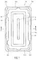
- FIG. 1 shows a view from below of a cover according to the invention, which is identified overall by reference number 10.
- a base 12 with different projections and recesses 14 for stiffening can be seen.
- edges 12a-d of the base 12 run between the four corner points 16ad, which - as can be seen - are designed with corresponding radii of curvature. It can be seen that the edges 12a to 12d do not span an exact rectangle between them, but rather are formed between two corresponding corner points 16a-d with a slightly convex curvature. It follows that the distance between the edges 12a, 12c is the smallest in the area of the corner points 16a, 16b or 16c, 16d, while the edges 12a, 12c in the middle between the corner points 16a, 16d or 16b, 16c the greatest width from each other exhibit.
- edges 12b i.e.
- FIG. 2 also shows that an edge section 18a, 18c extends upward from the curved edges 12a-12d, the sectional view according to FIG Figure 2 shows only the edge sections between the corner points 16a, 16d and 16b, 16c.
- FIG. 2 further shows that a circumferential flange edge 20 adjoins the corresponding edge sections 18a, 18c, the underside of which is also shown in FIG.
- FIG. 2 further illustrates that the edge sections 18a, 18c (and analogously the edge sections (not shown) running therebetween) are designed with a slight undercut with respect to a vertical plane running to the base of the floor 12, so that the opposite edge sections 18a, 18c have their greatest distance in the region of the edges 12a, 12c and their smallest distance in the region of the flange edge 20.
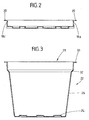
- FIG. 3 finally shows the basic structure of an associated container, which bears the reference numeral 22 here.
- the container 22 has a bottom 24, walls 26 running obliquely upwards and outwards and an opening mouth 28 with a support edge 30 running outwards on the edge side.
- the opening width of the opening mouth in the area of the support edge 30 is smaller than the base area of the bottom 12 of the associated cover 10, so that when the cover 10 is placed on the opening mouth 28, this initially in the area of the support edge 30 rests and can only be pressed into the opening mouth 28 by applying a certain force component, which is however relatively small, the opening mouth 28 expanding at the same time, due to the deformability of the walls 26 of the container 22 in the upper free edge area.
- the curved edges 12a to 12d of the bottom 12 of the lid 10 then come into contact with the corresponding inner surfaces of the opening mouth 28, continuously, here in particular linearly, whereby a complete sealing of the lid with respect to the container is achieved.
- the lid 10 is finally pushed in up to approximately the level 32 of the container 22 which can be seen in FIG. 3, at which moment the flange edge 20 of the lid 10 rests on the support edge 30 of the container 22.
- a container which has been closed in this way is no longer opened but disposed of, if appropriate in a waste incineration plant or the like.
- this is also possible, for example by inserting an appropriate tool between the support edge 30 and the flange edge 20 and prying open the cover 10.
Abstract
Description
Die Erfindung betrifft einen Deckel für Behälter mit im wesentlichen rechteckigem Öffnungsmund und nach außen abstehendem Auflagerand.The invention relates to a lid for containers with a substantially rectangular opening mouth and outwardly projecting support edge.
Derartige Behälter sind in vielfältiger Weise bekannt, insbesondere als Kunststoff-Behälter, und zwar in unterschiedlichsten Größen. Einen gattungsgemäßen Deckel und Behälter beschreibt die ER 0 049 430 B1. Es handelt sich um einen im Streckform-Verfahren hergestellten Kunststoff-Behälter mit einem Boden, vier mit leichter Schräge angeordneten Seitenwänden und einem umlaufenden, abstehenden Auflagerand.Such containers are known in a variety of ways, in particular as plastic containers, in a wide variety of sizes. ER 0 049 430 B1 describes a generic lid and container. It is a stretch-molded plastic container with a bottom, four side walls with a slight slope and a surrounding, protruding support edge.
Der zugehörige Deckel wird auf den Auflagerand nach Art eines Schnappverschlusses aufgedrückt.The associated lid is pressed onto the support edge in the manner of a snap lock.
Toleranzen, insbesondere bei der Herstellung des Behälters, führen dazu, daß der zugehörige Deckel den Behälter nicht immer vollständig luft- und feuchtigkeitsdicht abschließen kann. Eine entsprechende Forderung wird aber insbesondere bei Behältern für empfindliche Güter, wie infektiösen Müll oder umweltgefährdende Stoffe, erhoben.Tolerances, especially in the manufacture of the container, mean that the associated lid cannot always seal the container completely airtight and moisture-proof. A corresponding demand is made, in particular, for containers for sensitive goods, such as infectious waste or environmentally hazardous substances.
Zu diesem Zweck beschreibt die DE 36 04 925 A1 einen Schnappdeckel aus tiefgezogenem Kunststoff mit randseitig ausgebildeten, ins Deckelinnere vorspringenden Rastvorsprüngen, die den abstehenden Auflagerand des Behälters untergreifen sollen.For this purpose, DE 36 04 925 A1 describes a snap-on lid made of deep-drawn plastic with edge-shaped locking projections which protrude into the lid interior and which are intended to engage under the protruding bearing edge of the container.
Abgesehen davon, daß auch bei diesem Deckel Herstellungstoleranzen nicht immer sicher ausgeglichen werden können, besteht insbesondere für einen Deckel für Massenbehälter der Wunsch nach einer vereinfachten Herstellung.In addition to the fact that manufacturing tolerances cannot always be safely compensated for with this lid, there is a desire for simplified manufacturing, particularly for a lid for bulk containers.
Insoweit liegt der Erfindung die Aufgabe zugrunde, einen Deckel für einen Behälter der vorstehend genannten Art anzubieten, der einfach herstellbar ist, herstellungsbedingte Toleranzen des Behälters, insbesondere im Bereich des Öffnungsmundes ausgleichen kann und letztendlich einen möglichst vollständigen luft- und flüssigkeitsdichten Verschluß gewährleistet.In this respect, the invention has for its object to provide a lid for a container of the type mentioned above, which is easy to manufacture, can compensate for manufacturing tolerances of the container, in particular in the area of the opening mouth, and ultimately ensures the most complete air and liquid-tight seal possible.
Der Erfindung liegt die Erkenntnis zugrunde, daß ein in den rechteckigen Öffnungsmund eines Behälters eingesetzter Deckel häufig zumindest abschnittweise keinen flächigen Kontakt zu den korrespondierenden vertikalen Abschnitten der Wände im Bereich des Öffnungsmundes des Behälters aufgrund von Herstellungstoleranzen ermöglicht, so daß Spalte und Schlitze entstehen, durch die Luft und Flüssigkeit ein- und austreten kann.The invention is based on the knowledge that a lid inserted into the rectangular opening mouth of a container often does not allow, at least in sections, flat contact with the corresponding vertical sections of the walls in the region of the opening mouth of the container due to manufacturing tolerances, so that Gaps and slits are created through which air and liquid can enter and exit.
Gleichzeitig wurde erkannt, daß Behälter der genannten Art, insbesondere solche aus Kunststoff-Materialien, eine gewisse Elastizität aufweisen und eine gewisse Verformbarkeit des Behälters im Bereich des Öffnungsmundes ermöglichen.At the same time, it was recognized that containers of the type mentioned, in particular those made of plastic materials, have a certain elasticity and allow a certain deformability of the container in the region of the opening mouth.
Aufgrund dieser Erkenntnisse liegt der Erfindung der Gedanke zugrunde, die Verformbarkeit des Behälters im Bereich des Öffnungsmundes auszunutzen und durch eine Art "Über-dimensionierung" des korrespondierenden Abschnitts des Deckels den Öffnungsmund beim Aufsetzen des Deckels aufzuweiten, damit unter Vorspannung zu setzen und hierdurch eine erhöhte Flächenpressung zwischen den korrespondierenden Abschnitten von Deckel und Behälter zu erreichen.On the basis of these findings, the invention is based on the idea of utilizing the deformability of the container in the region of the opening mouth and of widening the opening mouth when the cover is put on by a kind of “over-dimensioning” of the corresponding section of the lid, thereby placing it under tension and thereby increasing it To achieve surface pressure between the corresponding sections of the lid and container.
Danach betrifft die Erfindung in ihrer allgemeinsten Ausführungsform einen Deckel für Behälter mit im wesentlichen rechteckigem Öffnungsmund und nach außen abstehendem Auflagerand mit folgenden Merkmalen:
- der Deckel besitzt einen Boden zum versenkten Einsatz in den Öffnungsmund des Behälters,
- die zwischen den Eckpunkten des Bodens verlaufenden Kanten sind zumindest abschnittweise konvex gestaltet, so daß die Grundfläche des Bodens insgesamt größer ist als die Öffnungsweite des Behälters im korrespondierenden Abschnitt,
- der Form der Kanten folgend verläuft vom Boden ein erster Randabschnitt im wesentlichen senkrecht vom Boden, der
- in einen, zum Auflagerand des Behälters parallel angeordneten Flanschrand übergeht.
- the lid has a bottom for insertion into the mouth of the container,
- the edges running between the corner points of the bottom are convex, at least in sections, so that the base area of the bottom is larger than the opening width of the container in the corresponding section,
- following the shape of the edges, a first edge section runs essentially perpendicularly from the bottom of the floor
- into a flange edge arranged parallel to the support edge of the container.
Der Deckel besitzt damit - abstrahiert betrachtet - im wesentlichen selbst eine Art Behälterform, jedoch mit sehr viel geringerer Tiefe als der Behälter.In abstract terms, the lid thus essentially has a type of container shape, but with a much smaller depth than the container.
Aufgrund der Gestaltung des Bodens mit einer Grundfläche, die aufgrund des konvexen Kantenverlaufs größer ist als die Öffnungsweite des Behälters im korrespondierenden Abschnitt liegt der Deckel, wenn er auf das offene Ende des Behälters aufgesetzt wird, dort zunächst lediglich lose auf. Je nachdem, in welcher Weise und in welchem Umfang die konvexen Krümmungsabschnitte ausgebildet sind, kann es sich dabei um einzelne Auflagepunkte oder Auflagelinien handeln.Due to the design of the base with a base area that is larger than the opening width of the container in the corresponding section due to the convex edge profile, the lid is initially only loosely there when it is placed on the open end of the container. Depending on the manner and the extent to which the convex curvature sections are formed, these can be individual support points or support lines.
Um den Deckel nun in der gewünschten Weise mit dem Behälter zu verbinden, ist es notwendig, ihn in den Öffnungsmund des Behälters hineinzudrücken. Hierzu ist - auch bei relativ dicken Wandstärken des Behälters - lediglich eine geringe Kraft notwendig, da der Behälter im Bereich des Öffnungsmundes, insbesondere im Bereich zwischen den Eckpunkten, eine gewisse Elastizität aufweist, die beim Eindrücken des Deckels die entsprechenden Flächenabschnitte des Behälterrandes beziehungsweise der Behälterwände nach außen drücken und so ein Einsetzen des Deckels ermöglichen.In order to connect the lid to the container in the desired manner, it is necessary to press it into the opening mouth of the container. For this purpose - even with relatively thick walls of the container - only a small force is necessary, since the container has a certain elasticity in the area of the opening mouth, in particular in the area between the corner points, which the corresponding surface sections of the container edge or the container walls when the lid is pressed in Push outwards and allow the cover to be inserted.
Der Deckel wird dabei so weit in den Öffnungsmund des Behälters hineingedrückt, bis er mit seinem Flanschrand auf dem Auflagerand des Behälters aufliegt.The lid is pressed into the opening mouth of the container until it lies with its flange edge on the support edge of the container.
Aufgrund der Verformung des Behälters im Bereich des Öffnungsmundes kommt es gleichzeitig im Bereich der korrespondierenden Flächenabschnitte des Randabschnittes des Deckels und des Öffnungsmundes des Behälters zu einer relativ hohen Flächenpressung, bedingt durch eine entsprechende Vorspannungsenergie, die zu dem überraschenden Ergebnis führt, daß ein mit dem genannten Deckel verschlossener Behälter eine hohe Dichtigkeit aufweist.Due to the deformation of the container in the area of the opening mouth, there is simultaneously a relatively high surface pressure in the area of the corresponding surface sections of the edge section of the lid and the opening mouth of the container, due to a corresponding preload energy, which leads to the surprising result that one with the said Lid of closed container has a high level of tightness.
Gleichzeitig werden etwaige Fertigungstoleranzen aufgrund der "Überdimensionierung" des Deckels im Verschlußbereich ausgeglichen.At the same time, any manufacturing tolerances due to the "oversizing" of the cover in the closure area are compensated.
Nach einer vorteilhaften Ausführungsform verlaufen die Kanten des Bodens zwischen den Eckpunkten jeweils mit einer durchgehenden konvexen Krümmung, so daß sich bei einem rechteckigen Behälter vier konvexe Seitenkanten des Deckelbodens ergeben.According to an advantageous embodiment, the edges of the base between the corner points each have a continuous convex curvature, so that there are four convex side edges of the cover base in a rectangular container.
Da der Behälter insbesondere in der Mitte zwischen zwei korrespondierenden Eckpunkten seine höchste Verformbarkeit zeigt, sieht eine weitere Ausführungsform vor, die Krümmungen so auszubilden, daß ihre Scheitelpunkte jeweils mittig zwischen den korrespondierenden Eckpunkten angeordnet sind. Dies minimiert den Kraftaufwand beim Einsetzen (Eindrücken) des Deckels in den Öffnungsmund des Behälters.Since the container shows its highest deformability, in particular in the middle between two corresponding corner points, a further embodiment provides for the curvatures to be designed in such a way that their apexes are arranged centrally between the corresponding corner points. This minimizes the effort required when inserting (pushing) the lid into the opening mouth of the container.
In diesem Sinne ist es weiter vorteilhaft, wenn die Randabschnitte zwischen den gekrümmten Kanten und dem umlaufenden Flanschrand zumindest abschnittweise mit einem Hinterschnitt (in bezug auf die Montageposition) ausgebildet sind. Auf diese Weise wird die Haftreibung beim Einsetzen des Deckels in den Behälter minimiert. Gleichzeitig hat sich gezeigt, daß die hierdurch im wesentlichen bedingte linienförmige Kontaktierung zwischen Deckel (im Kantenbereich des Bodens) und dem korrespondierenden Abschnitt der Seitenwände (des Öffnungsmundes) des Behälters völlig ausreicht, die gewünschte Dichtigkeit zu erreichen.In this sense, it is further advantageous if the edge sections between the curved edges and the circumferential flange edge are formed, at least in sections, with an undercut (with respect to the assembly position). In this way, static friction when inserting the lid into the container is minimized. At the same time, it has been shown that the line-shaped contact between the cover (in the edge region of the base) and the corresponding section of the side walls (the opening mouth) of the container, which is essentially caused by this, is completely sufficient to achieve the desired tightness.
Natürlich können die Randabschnitte auch umlaufend hinterschnitten ausgebildet werden.Of course, the edge sections can also be undercut all around.
Ein Hinterschnitt von 2 bis 5°, bezogen auf eine zum Boden verlaufende vertikale Ebene, hat sich als besonders vorteilhaft herausgestellt und läßt sich auch bei einem im Streckformverfahren hergestellten Kunststoff-Deckel ohne weiteres und ohne zusätzliche Werkzeuge realisieren. Ein solcher geringer Hinterschnitt erfordert keine Spezialwerkzeuge. Das Teil kann nach dem Verformungsvorgang ohne weiteres aus dem Werkzeug herausgezogen werden.An undercut of 2 to 5 °, based on a vertical plane running to the bottom, has been found to be particularly advantageous and can also be implemented easily and without additional tools even in the case of a plastic cover produced using the stretch-forming method. Such a small undercut does not require any special tools. The part can be easily removed from the tool after the shaping process.
Sofern dies für besondere Anwendungszwecke vorteilhaft erscheint, können der Übergangsbereich zwischen Boden und Randabschnitt beziehungsweise die Flächen des Randabschnitts mit einer umlaufenden Nut ausgebildet werden, die dann in einer Ebene parallel zum Boden verläuft. In diese Nut läßt sich ein Dichtring einsetzen, der den vollständigen Verschluß des Behälters zusätzlich verbessert.If this appears to be advantageous for special application purposes, the transition area between the floor and the edge section or the surfaces of the edge section can be formed with a circumferential groove which then runs parallel to the floor in one plane. A sealing ring can be inserted into this groove, which additionally improves the complete closure of the container.
Dem Fachmann stehen darüber hinaus zahlreiche weitere Möglichkeiten der Optimierung zur Verfügung. So ist es möglich, den Öffnungsmund des Behälters mit einer zusätzlichen Stufe auszubilden, die in einem solchen Abstand unterhalb des umlaufenden Auflagerandes ausgebildet wird, die der Höhe des Randabschnittes des Deckels entspricht, so daß dieser nicht nur mit seinem umlaufenden Flanschrand auf dem Auflagerand, sondern zusätzlich auch noch auf der genannten Stufe aufliegt.The expert also has numerous other optimization options available. So it is possible to form the opening mouth of the container with an additional step, which is formed at such a distance below the circumferential support edge that corresponds to the height of the edge portion of the lid, so that this not only with its circumferential flange edge on the support edge, but also lies on the level mentioned.
Vor- und Rücksprünge im Boden des Deckels können diesen zusätzlich versteifen. Ebenso sind Stapelkanten oder dergleichen möglich. Zu diesem Zweck kann es vorteilhaft sein, den Boden des Deckels, zum Beispiel in der Mitte, nach oben auszuformen, um so Stapelhilfen auszubilden.Projections and recesses in the bottom of the lid can additionally stiffen it. Stacked edges or the like are also possible. For this purpose, it can be advantageous to shape the bottom of the lid, for example in the middle, upwards, in order to form stacking aids.
Wenngleich die Erfindung vorstehend anhand eines im Streckformverfahren hergestellten Deckels für einen Kunststoff-Behälter erläutert wurde, lassen sich die erfindungsgemäßen Merkmale auch an Deckeln und/oder Behältern aus anderen Werkstoffen oder nach anderen Verfahren hergestellten Deckeln und Behältern realisieren. Voraussetzung ist lediglich, daß der Behälter im Bereich des Öffnungsmundes eine gewisse Verformbarkeit aufweist.Although the invention has been explained above with reference to a cover for a plastic container produced by the stretch-forming process, the features according to the invention can also be implemented on covers and / or containers made of other materials or covers and containers produced by other methods. The only requirement is that the container has a certain deformability in the area of the opening mouth.
Weitere Merkmale der Erfindung ergeben sich aus den Merkmalen der Unteransprüche sowie den sonstigen Anmeldungsunterlagen.Further features of the invention result from the features of the subclaims and the other application documents.
Die Erfindung wird nachstehend anhand eines Ausführungsbeispieles - in schematisierter Darstellung - näher erläutert. Dabei zeigen:
- Figur 1:
- eine Aufsicht auf einen erfindungsgemäßen Deckel von unten
- Figur 2:
- einen Längsschnitt durch den Deckel nach Figur 1 entlang - II - II nach Figur 1
- Figur 3:
- einen Längsschnitt durch einen zugehörigen Behälter an der in Figur 1 mit II - II gekennzeichneten Stelle.
- Figure 1:
- a top view of a lid according to the invention from below
- Figure 2:
- a longitudinal section through the lid of Figure 1 along - II - II of Figure 1
- Figure 3:
- a longitudinal section through an associated container at the point marked II - II in Figure 1.
Figur 1 zeigt eine Ansicht von unten auf einen erfindungsgemäßen Deckel, der insgesamt mit dem Bezugszeichen 10 gekennzeichnet ist. Zu erkennen ist ein Boden 12 mit verschiedenen Vor- und Rücksprüngen 14 zur Versteifung.FIG. 1 shows a view from below of a cover according to the invention, which is identified overall by
Zwischen den vier Eckpunkten 16 a-d, die - wie zu erkennen ist - mit entsprechenden Krümmungsradien ausgebildet sind, verlaufen die vier Kanten 12a-d des Bodens 12. Zu erkennen ist, daß die Kanten 12a bis 12d kein exaktes Rechteck zwischen sich aufspannen, sondern vielmehr zwischen jeweils zwei korrespondierenden Eckpunkten 16a-d mit leicht konvexer Krümmung ausgebildet sind. Daraus folgt, daß der Abstand der Kanten 12a, 12c im Bereich der Eckpunkte 16a, 16b beziehungsweise 16c, 16d jeweils am geringsten ist, während die Kanten 12a, 12c in der Mitte zwischen den Eckpunkten 16a, 16d beziehungsweise 16b, 16c die größte Weite voneinander aufweisen.The four
Analog gilt dies auch für die Kanten 12b, d.Analogously, this also applies to the edges 12b, i.e.
Figur 2 läßt sich weiter entnehmen, daß sich von den gekrümmten Kanten 12a-12d jeweils ein Randabschnitt 18a, 18c nach oben erstreckt, wobei die Schnittdarstellung nach Figur 2 lediglich die Randabschnitte zwischen den Eckpunkten 16a, 16d und 16b, 16c erkennen läßt.FIG. 2 also shows that an
Figur 2 zeigt weiter, daß sich an die entsprechenden Randabschnitte 18a, 18c ein umlaufender Flanschrand 20 anschließt, dessen Unterseite ebenfalls in Figur 1 dargestellt ist.FIG. 2 further shows that a
Figur 2 veranschaulicht weiter, daß die Randabschnitte 18a, 18c (und analog die (nicht dargestellten), dazwischen verlaufenden Randabschnitte) mit einem geringen Hinterschnitt, bezogen auf eine zur Grundfläche des Bodens 12 verlaufende vertikale Ebene ausgebildet sind, so daß die gegenüberliegenden Randabschnitte 18a, 18c im Bereich der Kanten 12a, 12c ihren größten Abstand und im Bereich des Flanschrandes 20 ihren geringsten Abstand aufweisen.FIG. 2 further illustrates that the
Figur 3 schließlich zeigt den prinzipiellen Aufbau eines zugehörigen Behälters, der hier das Bezugszeichen 22 trägt. Der Behälter 22 besitzt einen Boden 24,schräg nach oben und außen verlaufende Wände 26 und einen Öffnungsmund 28 mit einem randseitig nach außen verlaufenden Auflagerand 30.Figure 3 finally shows the basic structure of an associated container, which bears the
Für das Verständnis der Erfindung ist es wichtig, daß die Öffnungsweite des Öffnungsmundes im Bereich des Auflagerandes 30 kleiner ist als die Grundfläche des Bodens 12 des zugehörigen Deckels 10, so daß beim Aufsetzen des Deckels 10 auf den Öffnungsmund 28 dieser zunächst im Bereich des Auflagerandes 30 aufliegt und erst durch Aufbringen einer bestimmten Kraftkomponente, die jedoch relativ gering ist, in den Öffnungsmund 28 hineingedrückt werden kann, wobei sich der Öffnungsmund 28 gleichzeitig aufweitet, aufgrund der Verformbarkeit der Wände 26 des Behälters 22 im oberen freien Randbereich. Gleichzeitig kommen dann die gekrümmten Kanten 12a bis 12d des Bodens 12 des Deckels 10 gegen die entsprechenden Innenflächen des Öffnungsmundes 28 zur Anlage, und zwar durchgehend, hier insbesondere linienförmig, wodurch eine vollständige Abdichtung des Deckels gegenüber dem Behälter erreicht wird. Der Deckel 10 wird schließlich bis etwa zu der in Figur 3 erkennbaren Stufe 32 des Behälters 22 hineingedrückt, wobei in diesem Moment der Flanschrand 20 des Deckels 10 auf dem Auflagerand 30 des Behälters 22 aufliegt.For the understanding of the invention, it is important that the opening width of the opening mouth in the area of the
In der Regel wird ein so einmal verschlossener Behälter nicht mehr geöffnet, sondern entsorgt, gegebenenfalls in einer Müllverbrennungsanlage oder dergleichen. Muß er jedoch noch einmal geöffnet werden, so ist auch dies möglich, beispielsweise durch Einführen eines entsprechenden Werkzeuges zwischen den Auflagerand 30 und den Flanschrand 20 und ein Aufhebeln des Deckels 10.As a rule, a container which has been closed in this way is no longer opened but disposed of, if appropriate in a waste incineration plant or the like. However, if it has to be opened again, this is also possible, for example by inserting an appropriate tool between the
Claims (8)
Applications Claiming Priority (2)
| Application Number | Priority Date | Filing Date | Title |
|---|---|---|---|
| DE4200944 | 1992-01-16 | ||
| DE4200944A DE4200944A1 (en) | 1992-01-16 | 1992-01-16 | CONTAINER LID |
Publications (3)
| Publication Number | Publication Date |
|---|---|
| EP0551908A2 true EP0551908A2 (en) | 1993-07-21 |
| EP0551908A3 EP0551908A3 (en) | 1993-08-18 |
| EP0551908B1 EP0551908B1 (en) | 1995-04-05 |
Family
ID=6449599
Family Applications (1)
| Application Number | Title | Priority Date | Filing Date |
|---|---|---|---|
| EP93100502A Expired - Lifetime EP0551908B1 (en) | 1992-01-16 | 1993-01-15 | Container lid |
Country Status (3)
| Country | Link |
|---|---|
| EP (1) | EP0551908B1 (en) |
| AT (1) | ATE120705T1 (en) |
| DE (2) | DE4200944A1 (en) |
Cited By (3)
| Publication number | Priority date | Publication date | Assignee | Title |
|---|---|---|---|---|
| EP0652161A1 (en) * | 1993-11-10 | 1995-05-10 | Lucas Industries Public Limited Company | Small goods carrier |
| EP0798236A1 (en) * | 1996-03-30 | 1997-10-01 | LENTJES, Carsten | Lid for closing containers |
| EP0798235A1 (en) * | 1996-03-30 | 1997-10-01 | LENTJES, Carsten | Lid-shaped closing element for a trash bag |
Citations (5)
| Publication number | Priority date | Publication date | Assignee | Title |
|---|---|---|---|---|
| US2575490A (en) * | 1944-12-22 | 1951-11-20 | Continental Can Co | Friction plug closure |
| GB1213150A (en) * | 1967-12-23 | 1970-11-18 | James Gregg | Improvements in or relating to lids |
| CH554266A (en) * | 1972-09-11 | 1974-09-30 | Freisinger Franz Gmbh & Co Kg | CAN. |
| GB1495704A (en) * | 1973-12-14 | 1977-12-21 | Metal Box Co Ltd | Containers with metal plug lids |
| EP0049430B1 (en) * | 1980-10-01 | 1984-04-11 | Theodor Lentjes | Bulk goods container with lid for use as a disposable transport cask |
Family Cites Families (4)
| Publication number | Priority date | Publication date | Assignee | Title |
|---|---|---|---|---|
| DE1869339U (en) * | 1963-01-03 | 1963-03-21 | Novoplast Schellhorn K G | CONTAINER WITH SNAP LID. |
| DE7806380U1 (en) * | 1978-03-03 | 1978-06-15 | Bellaplast Gmbh | Thin-walled container lid |
| NL8601752A (en) * | 1986-07-04 | 1988-02-01 | Wavin Bv | RE-CLOSABLE PACK CONTAINING A HOLDER AND A LID FITTING ON THE HOLDER. |
| ES1003793Y (en) * | 1987-11-10 | 1990-03-16 | Llamas, S.A. | PERFECTED METAL CONTAINER GIVEN WITH ITS CORRESPONDING LID WITH HERMETIC CLOSURE. |
-
1992
- 1992-01-16 DE DE4200944A patent/DE4200944A1/en not_active Withdrawn
-
1993
- 1993-01-15 EP EP93100502A patent/EP0551908B1/en not_active Expired - Lifetime
- 1993-01-15 AT AT93100502T patent/ATE120705T1/en active
- 1993-01-15 DE DE59300114T patent/DE59300114D1/en not_active Expired - Lifetime
Patent Citations (5)
| Publication number | Priority date | Publication date | Assignee | Title |
|---|---|---|---|---|
| US2575490A (en) * | 1944-12-22 | 1951-11-20 | Continental Can Co | Friction plug closure |
| GB1213150A (en) * | 1967-12-23 | 1970-11-18 | James Gregg | Improvements in or relating to lids |
| CH554266A (en) * | 1972-09-11 | 1974-09-30 | Freisinger Franz Gmbh & Co Kg | CAN. |
| GB1495704A (en) * | 1973-12-14 | 1977-12-21 | Metal Box Co Ltd | Containers with metal plug lids |
| EP0049430B1 (en) * | 1980-10-01 | 1984-04-11 | Theodor Lentjes | Bulk goods container with lid for use as a disposable transport cask |
Cited By (3)
| Publication number | Priority date | Publication date | Assignee | Title |
|---|---|---|---|---|
| EP0652161A1 (en) * | 1993-11-10 | 1995-05-10 | Lucas Industries Public Limited Company | Small goods carrier |
| EP0798236A1 (en) * | 1996-03-30 | 1997-10-01 | LENTJES, Carsten | Lid for closing containers |
| EP0798235A1 (en) * | 1996-03-30 | 1997-10-01 | LENTJES, Carsten | Lid-shaped closing element for a trash bag |
Also Published As
| Publication number | Publication date |
|---|---|
| EP0551908B1 (en) | 1995-04-05 |
| DE4200944A1 (en) | 1993-07-22 |
| DE59300114D1 (en) | 1995-05-11 |
| EP0551908A3 (en) | 1993-08-18 |
| ATE120705T1 (en) | 1995-04-15 |
Similar Documents
| Publication | Publication Date | Title |
|---|---|---|
| CH657589A5 (en) | SCREW CAP WITH INTERNAL AND EXTERNAL COVER. | |
| CH654807A5 (en) | CONTAINER LID. | |
| EP1840440B1 (en) | Corner bracket | |
| EP0551908B1 (en) | Container lid | |
| DE102017107675A1 (en) | Plastic containers with in-mold label | |
| DE19641686A1 (en) | Stackable storage and transport container | |
| DE19952214B4 (en) | Cup-shaped screw cap | |
| AT393600B (en) | DRAWER | |
| DE2837659A1 (en) | Multiple layer can packing unit - has lat sheets forming layer support plates with holders along edges each having self-adhesive strips | |
| EP0294781B1 (en) | Device for securing a can lid, especially for a paint can | |
| DE602006000003T2 (en) | Device for storing a seal | |
| DE102007014022A1 (en) | Deep-drawn components produced from sheet metal have dome-shaped supporting structures formed in their edges, allowing components to be stacked | |
| EP0652161B1 (en) | Small goods carrier | |
| WO2001085564A1 (en) | Container with body and lid | |
| DE19927069C2 (en) | transport container | |
| DE19704945B4 (en) | Stackable box | |
| AT395641B (en) | SEAL ARRANGEMENT | |
| EP0241780A2 (en) | Container for gas-releasing products | |
| EP1510467B1 (en) | Rectangular lid made by deep drawing of a plastic sheet | |
| EP0694478A1 (en) | Cup-shaped container | |
| DE2903190C2 (en) | Folding box packaging | |
| DE102015120065A1 (en) | transport container | |
| AT7002U1 (en) | TRANSPORT CONTAINERS, ESPECIALLY STACKED CONTAINERS | |
| DE8608897U1 (en) | Container for gassing products | |
| DE102022112330A1 (en) | Plant container with label slot |
Legal Events
| Date | Code | Title | Description |
|---|---|---|---|
| PUAI | Public reference made under article 153(3) epc to a published international application that has entered the european phase |
Free format text: ORIGINAL CODE: 0009012 |
|
| PUAL | Search report despatched |
Free format text: ORIGINAL CODE: 0009013 |
|
| AK | Designated contracting states |
Kind code of ref document: A2 Designated state(s): AT BE CH DE DK ES FR GB GR IT LI NL PT SE |
|
| AK | Designated contracting states |
Kind code of ref document: A3 Designated state(s): AT BE CH DE DK ES FR GB GR IT LI NL PT SE |
|
| 17P | Request for examination filed |
Effective date: 19930831 |
|
| 17Q | First examination report despatched |
Effective date: 19940923 |
|
| GRAA | (expected) grant |
Free format text: ORIGINAL CODE: 0009210 |
|
| STAA | Information on the status of an ep patent application or granted ep patent |
Free format text: STATUS: THE PATENT HAS BEEN GRANTED |
|
| AK | Designated contracting states |
Kind code of ref document: B1 Designated state(s): AT BE CH DE DK ES FR GB GR IT LI NL PT SE |
|
| PG25 | Lapsed in a contracting state [announced via postgrant information from national office to epo] |
Ref country code: GR Free format text: LAPSE BECAUSE OF FAILURE TO SUBMIT A TRANSLATION OF THE DESCRIPTION OR TO PAY THE FEE WITHIN THE PRESCRIBED TIME-LIMIT Effective date: 19950405 Ref country code: ES Free format text: THE PATENT HAS BEEN ANNULLED BY A DECISION OF A NATIONAL AUTHORITY Effective date: 19950405 Ref country code: DK Effective date: 19950405 |
|
| REF | Corresponds to: |
Ref document number: 120705 Country of ref document: AT Date of ref document: 19950415 Kind code of ref document: T |
|
| GBT | Gb: translation of ep patent filed (gb section 77(6)(a)/1977) |
Effective date: 19950405 |
|
| ITF | It: translation for a ep patent filed |
Owner name: DR. ING. A. RACHELI & C. |
|
| REF | Corresponds to: |
Ref document number: 59300114 Country of ref document: DE Date of ref document: 19950511 |
|
| ET | Fr: translation filed | ||
| PG25 | Lapsed in a contracting state [announced via postgrant information from national office to epo] |
Ref country code: SE Effective date: 19950705 Ref country code: PT Effective date: 19950705 |
|
| PG25 | Lapsed in a contracting state [announced via postgrant information from national office to epo] |
Ref country code: LI Effective date: 19960131 Ref country code: CH Effective date: 19960131 |
|
| PLBE | No opposition filed within time limit |
Free format text: ORIGINAL CODE: 0009261 |
|
| 26N | No opposition filed | ||
| REG | Reference to a national code |
Ref country code: CH Ref legal event code: PL |
|
| REG | Reference to a national code |
Ref country code: GB Ref legal event code: IF02 |
|
| PGFP | Annual fee paid to national office [announced via postgrant information from national office to epo] |
Ref country code: FR Payment date: 20120201 Year of fee payment: 20 |
|
| PGFP | Annual fee paid to national office [announced via postgrant information from national office to epo] |
Ref country code: DE Payment date: 20111223 Year of fee payment: 20 |
|
| PGFP | Annual fee paid to national office [announced via postgrant information from national office to epo] |
Ref country code: GB Payment date: 20120124 Year of fee payment: 20 Ref country code: BE Payment date: 20120123 Year of fee payment: 20 Ref country code: IT Payment date: 20120126 Year of fee payment: 20 |
|
| PGFP | Annual fee paid to national office [announced via postgrant information from national office to epo] |
Ref country code: NL Payment date: 20120127 Year of fee payment: 20 |
|
| REG | Reference to a national code |
Ref country code: DE Ref legal event code: R071 Ref document number: 59300114 Country of ref document: DE |
|
| REG | Reference to a national code |
Ref country code: NL Ref legal event code: V4 Effective date: 20130115 |
|
| BE20 | Be: patent expired |
Owner name: *LENTJES CARSTEN Effective date: 20130115 |
|
| REG | Reference to a national code |
Ref country code: GB Ref legal event code: PE20 Expiry date: 20130114 |
|
| REG | Reference to a national code |
Ref country code: AT Ref legal event code: MK07 Ref document number: 120705 Country of ref document: AT Kind code of ref document: T Effective date: 20130115 |
|
| PGFP | Annual fee paid to national office [announced via postgrant information from national office to epo] |
Ref country code: AT Payment date: 20120123 Year of fee payment: 20 |
|
| PG25 | Lapsed in a contracting state [announced via postgrant information from national office to epo] |
Ref country code: DE Free format text: LAPSE BECAUSE OF EXPIRATION OF PROTECTION Effective date: 20130116 Ref country code: GB Free format text: LAPSE BECAUSE OF EXPIRATION OF PROTECTION Effective date: 20130114 |