EP0551151A1 - Television receiver - Google Patents
Television receiver Download PDFInfo
- Publication number
- EP0551151A1 EP0551151A1 EP93200003A EP93200003A EP0551151A1 EP 0551151 A1 EP0551151 A1 EP 0551151A1 EP 93200003 A EP93200003 A EP 93200003A EP 93200003 A EP93200003 A EP 93200003A EP 0551151 A1 EP0551151 A1 EP 0551151A1
- Authority
- EP
- European Patent Office
- Prior art keywords
- memory
- data
- teletext
- display
- page
- Prior art date
- Legal status (The legal status is an assumption and is not a legal conclusion. Google has not performed a legal analysis and makes no representation as to the accuracy of the status listed.)
- Granted
Links
Images


Classifications
-
- H—ELECTRICITY
- H04—ELECTRIC COMMUNICATION TECHNIQUE
- H04N—PICTORIAL COMMUNICATION, e.g. TELEVISION
- H04N21/00—Selective content distribution, e.g. interactive television or video on demand [VOD]
- H04N21/40—Client devices specifically adapted for the reception of or interaction with content, e.g. set-top-box [STB]; Operations thereof
- H04N21/47—End-user applications
- H04N21/488—Data services, e.g. news ticker
- H04N21/4888—Data services, e.g. news ticker for displaying teletext characters
-
- G—PHYSICS
- G09—EDUCATION; CRYPTOGRAPHY; DISPLAY; ADVERTISING; SEALS
- G09G—ARRANGEMENTS OR CIRCUITS FOR CONTROL OF INDICATING DEVICES USING STATIC MEANS TO PRESENT VARIABLE INFORMATION
- G09G5/00—Control arrangements or circuits for visual indicators common to cathode-ray tube indicators and other visual indicators
- G09G5/22—Control arrangements or circuits for visual indicators common to cathode-ray tube indicators and other visual indicators characterised by the display of characters or indicia using display control signals derived from coded signals representing the characters or indicia, e.g. with a character-code memory
- G09G5/222—Control of the character-code memory
-
- H—ELECTRICITY
- H04—ELECTRIC COMMUNICATION TECHNIQUE
- H04N—PICTORIAL COMMUNICATION, e.g. TELEVISION
- H04N7/00—Television systems
- H04N7/08—Systems for the simultaneous or sequential transmission of more than one television signal, e.g. additional information signals, the signals occupying wholly or partially the same frequency band, e.g. by time division
- H04N7/087—Systems for the simultaneous or sequential transmission of more than one television signal, e.g. additional information signals, the signals occupying wholly or partially the same frequency band, e.g. by time division with signal insertion during the vertical blanking interval only
- H04N7/088—Systems for the simultaneous or sequential transmission of more than one television signal, e.g. additional information signals, the signals occupying wholly or partially the same frequency band, e.g. by time division with signal insertion during the vertical blanking interval only the inserted signal being digital
- H04N7/0884—Systems for the simultaneous or sequential transmission of more than one television signal, e.g. additional information signals, the signals occupying wholly or partially the same frequency band, e.g. by time division with signal insertion during the vertical blanking interval only the inserted signal being digital for the transmission of additional display-information, e.g. menu for programme or channel selection
-
- H—ELECTRICITY
- H04—ELECTRIC COMMUNICATION TECHNIQUE
- H04N—PICTORIAL COMMUNICATION, e.g. TELEVISION
- H04N21/00—Selective content distribution, e.g. interactive television or video on demand [VOD]
- H04N21/40—Client devices specifically adapted for the reception of or interaction with content, e.g. set-top-box [STB]; Operations thereof
- H04N21/41—Structure of client; Structure of client peripherals
- H04N21/422—Input-only peripherals, i.e. input devices connected to specially adapted client devices, e.g. global positioning system [GPS]
- H04N21/42204—User interfaces specially adapted for controlling a client device through a remote control device; Remote control devices therefor
-
- H—ELECTRICITY
- H04—ELECTRIC COMMUNICATION TECHNIQUE
- H04N—PICTORIAL COMMUNICATION, e.g. TELEVISION
- H04N21/00—Selective content distribution, e.g. interactive television or video on demand [VOD]
- H04N21/40—Client devices specifically adapted for the reception of or interaction with content, e.g. set-top-box [STB]; Operations thereof
- H04N21/43—Processing of content or additional data, e.g. demultiplexing additional data from a digital video stream; Elementary client operations, e.g. monitoring of home network or synchronising decoder's clock; Client middleware
- H04N21/431—Generation of visual interfaces for content selection or interaction; Content or additional data rendering
- H04N21/4312—Generation of visual interfaces for content selection or interaction; Content or additional data rendering involving specific graphical features, e.g. screen layout, special fonts or colors, blinking icons, highlights or animations
- H04N21/4316—Generation of visual interfaces for content selection or interaction; Content or additional data rendering involving specific graphical features, e.g. screen layout, special fonts or colors, blinking icons, highlights or animations for displaying supplemental content in a region of the screen, e.g. an advertisement in a separate window
-
- H—ELECTRICITY
- H04—ELECTRIC COMMUNICATION TECHNIQUE
- H04N—PICTORIAL COMMUNICATION, e.g. TELEVISION
- H04N21/00—Selective content distribution, e.g. interactive television or video on demand [VOD]
- H04N21/40—Client devices specifically adapted for the reception of or interaction with content, e.g. set-top-box [STB]; Operations thereof
- H04N21/47—End-user applications
-
- H—ELECTRICITY
- H04—ELECTRIC COMMUNICATION TECHNIQUE
- H04N—PICTORIAL COMMUNICATION, e.g. TELEVISION
- H04N5/00—Details of television systems
- H04N5/44—Receiver circuitry for the reception of television signals according to analogue transmission standards
- H04N5/445—Receiver circuitry for the reception of television signals according to analogue transmission standards for displaying additional information
- H04N5/44504—Circuit details of the additional information generator, e.g. details of the character or graphics signal generator, overlay mixing circuits
Definitions
- the invention relates to a television receiver including a teletext processor including character generator means and teletext page memory means for receiving, decoding and displaying teletext data, means for generating an on-screen message display, the on-screen message display generating means including a further memory means storing the required data for the on-screen message display, and microprocessor means for controlling the teletext processor and the on-screen message display generating means.
- a teletext processor including character generator means and teletext page memory means for receiving, decoding and displaying teletext data, means for generating an on-screen message display, the on-screen message display generating means including a further memory means storing the required data for the on-screen message display, and microprocessor means for controlling the teletext processor and the on-screen message display generating means.
- Such a television receiver is disclosed in US Patent No. 4633297.
- the on-screen display messages are stored in a read-only memory (ROM) which is read out under control of a microprocessor into the television page memory.
- ROM read-only memory
- Appropriate memory timing and control arrangements select whether the teletext data being received or the stored pages from the on-screen display ROM are written into selected locations of the teletext page memory.
- Data from the teletext page memory is then fed to a character generator which provides the signal for driving the display device.
- This arrangement enables on-screen display messages to be overlayed on the teletext data merely by writing on-screen display message data from the ROM into the teletext page memory at the appropriate locations.
- 4633297 is that when the on-screen display message is deleted, it will take an indeterminate time for the teletext data to be read into the locations of the memory which had held the on-screen display data, the time depending on the position within the transmitting cycle of the teletext information when the on-screen display message is deleted.
- the invention provides a television receiver as set forth in the opening paragraph, characterised by selection means for selectively reading data from the display memory and the further memory to the character generator.
- the display of both teletext data and on-screen message display data can be combined on the display screen such that the on-screen message display data overwrites the teletext page data.
- the full teletext display data is immediately available as soon as the on-screen display data is deleted. Consequently, it is not necessary to wait for position in the cycle of teletext pages where the relevant page information is transmitted to arrive before restoring the teletext display and the on-screen message display can be instantly inserted and deleted without affecting the availability of the teletext data for display.
- the selection means may be controlled by data read from given locations of the teletext page memory. This allows a simple latch circuit to control the operation of a multiplexer which selects the output from either the display memory or the further memory.
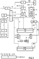
- the teletext television receiver shown in Figure 1 comprises video and data processing circuits for receiving and displaying both normal picture information and teletext information.
- the front end FE of the receiver comprises conventional amplifying, tuning, intermediate frequency and detector circuits and is connected to receive an incoming video signal VS.
- the demodulated video signal VS' is applied to a colour decoder which produces the RGB component signals for the picture display.
- Time base circuits for a display device DT for example a cathode ray tube, receive the usual line and field synchronising pulses from a separator circuit which extracts the synchronising pulses from the video signal VS'.
- the element CD represents the colour decoder and these other circuits which are provided for normal picture display.
- the demodulated video signal VS' is also applied to a teletext decoding section of the television receiver.
- This section deals with the reception and display of alpha numeric text and other teletext information which is received as digitally coded data. It comprises a video processor circuit VP, a data acquisition circuit DAC, a character generator CG, and a page memory PM.
- the video processor circuit VP performs inter alia data slicing for retrieving teletext data pulses D from the video signal VS' together with input data clock pulses C which are derived from the data pulses D.
- the data pulses D and clock pulses C are fed to the data acquisition circuit DAC which is operable to feed selected groups of the teletext data pulses over an acquisition connection ACQ to a page memory interface circuit MIC as digital codes representing address, display, and control information.
- the page memory PM which has a capacity for storing the display and control information for at least one teletext display page, stores the acquired display and control information as digital codes at respective memory locations as determined by the accompanying address information.
- a logic processor PRO controls the operation of the teletext decoder section via a processor interface circuit INT.
- the processor PRO is operable in accordance with a page select signal S applied to it from a receiver circuit RR, which forms part of a remote control arrangement RC, to determine which teletext information is acquired by the data acquisition circuit DAC.
- the remote control arrangement RC further comprises a key pad KP and a transmitter TX forming the usual remote control unit supplied with many television receivers.
- the processor PRO is operable to access the page memory PM over a connection X, to read out from the page memory PM the stored digital codes for application via a connection DSP1 and DSP to the character generator CG.
- the character generator CG is responsive to the applied digital codes to produce RGB component signals for displaying the selected page.
- the character generator CG comprises character memory CM and an associated addressing circuit CMA.
- Character information representing the character shapes available for display is stored in the character memory CM which is selectively addressed by addressing circuits CMA in accordance with the digital code applied to the character generator CG from the page memory PM.
- the character information for each character shape is stored in at least one individual character memory location which is addressable by a respective one of the digital codes. Only a portion of the character information for a character shape is read out at any one time which portion is displayed in a current scanning line of the display.
- a timing circuit TC provides timing signals on connections T1 to T3 for the circuit elements DAC CG and MIC. The operation of the timing circuit TC is synchronised with the received video signal VS by a composite signal VCS which contains the line and field synchronising pulses as separated from the demodulated video signal VS' in the video processor VP.
- the teletext decoder section for teletext information acquisition together with the front end FE may be provided as a separate teletext decoder which is adapted to feed a display monitor or a conventional television receiver.
- the teletext decoder could be embedded within a video cassette recorder whose output feeds a conventional television receiver.
- the teletext receiver as described so far is the same as that described in U.K. Patent Application No. 2223650 (PHB 33497) and for the present purposes it will be assumed that the teletext information to be processed by a teletext decoder embodying the present invention conforms to the specification laid down in the document World System Teletext and Data Broadcasting System, December 1987 published by The U.K. Department of Trade and Industry.
- a quantity of teletext information to be considered as an entity is termed a page. All the pages which are available are normally transmitted in a recurrent cycle with or without updating page information as appropriate.
- the pages are numbered and the teletext decoder is operable to select any page by number and the digital codes representing the page information are acquired by the teletext decoder from the cyclic transmission and stored in the page memory for as long as the page is required.
- the page information comprises digital codes representing display and control information and addresses for up to 24 display rows each having 40 character positions.
- the first display row, (row 0) of each page is termed a page header and contains inter alia the page number.
- the page information for a page can also include one or more extension date packets which are received and stored in page memory along with the basic display information for the page concerned.
- Such an extension data packet can for example be used to change the character which is to be displayed at a particular character position and in particular may include data from which row attributes which define the background colour for each row to be displayed can be derived.
- the page memory PM1 holds data contained in row 25 of the teletext page.
- Row 25 is not displayed on the display device but contains a number of control characters.
- the last 14 columns of row 25 contain the row attributes. These comprise a 3 bit number for each teletext row and the areas at the top and bottom of the screen outside the normal text display area to define the default background colour for the row.
- the processor PRO is also arranged to control the receiver and includes in this function the creation of on-screen display messages to indicate to the user the function being controlled.
- the data required to display these on-screen display messages is supplied to the page memory PM over the connection X and is arranged to overwrite the acquired teletext data which was previously present in the page memory PM. This overwriting may be on a row by row basis so that only that portion of the teletext display page which is occupied by the on-screen display message is overwritten.
- the receiver shown in Figure 1 further comprises a second auxiliary page memory APM which holds the on-screen display information and has associated with it a memory interface circuit AMIC.
- the processor PRO accesses the memory APM over the connection Y through the interface circuit AMIC to enable the required on-screen display data to be selected and read out at the appropriate times.
- the memory APM may be either a read only memory programmed with all available on-screen display messages or may be a read/write memory, the on-screen display messages being alterable by the processor PRO.
- the output DSP2 from the auxiliary page memory APM is fed to a multiplexer MUX whose output provides the signal DSP to the character generator CG.
- the multiplexer MUX is arranged to select the data for display from either the page memory PM or the auxilliary page memory APM. This is done on the basis of selecting a row for display either from the memory PM or from the memory APM. For each row a bit is stored in the memory PM which specifies whether the row should be displayed from the memory PM or the memory APM. This bit is set by the processor PRO via the connection X.
- the memory interface circuit MIC applies the bit associated with the row to be displayed to a latch L which is clocked by a signal T4 at the row frequency. The signal T4 is derived from the timing circuit TC.
- the output OSD of the latch L controls the multiplexer MUX to select the data to be displayed from either the page memory PM or the auxiliary memory APM.
- Row 25 is not displayed on the display device but contains a number of control characters.
- the last 14 characters of row 25 contain the row attributes. These comprise a 3 bit number for each teletext row and the areas at the top and bottom of the screen outside the normal text display area. These 3 bit numbers define the default background colour for the row.
- they contain a bit for each text row to indicate whether the row should be displayed from the page memory PM or from the auxiliary memory APM. It is this last bit which is set to define from which memory the display is derived for each row. The state of this bit determines whether the latch L becomes set. The state of the output of the latch L causes the multiplexer MUX to select data from the desired memory.
- Figure 2 shows the layout of the memory corresponding to the last 14 columns of row 25 which contains the row attributes. These contain a bit for each text row to indicate whether the rows should be displayed from the normal or the auxiliary memory and a 3 bit number for each teletext row and for the areas at the top and bottom of the screen outside the normal text display area to define the default background colour for that row.
- Bit N ⁇ /S defines whether text for the row comes from the memory PM or from the auxiliary memory APM.
- N ⁇ -/S is set to specify the memory from which the data is read out via the multiplexer MUX by the processor PRO over the connection X according to whether teletext data or on-screen display data is to be displayed.
- the arrangement shown in Figure 1 is capable of inserting on-screen display messages from the auxiliary memory APM but is limited to selecting data from the memory PM or from the auxiliary memory APM for a complete row, that is in one display row information from only one of the memories PM and APM can be displayed.
- Figure 3 shows an arrangement in which boxed messages as illustrated in Figure 4 can be displayed, that is the data for display can be taken from both the memory PM and the auxiliary memory APM for the same row.
- the processor PRO through the interface unit INT produces a signal SC which is the display character on which the on-screen display message is to start. This is fed to a first input of a comparator COMP.
- a second input of the comparator COMP receives a signal DC from the timing control circuit ATC.
- SC which represents the display character at which the on-screen display is to start
- the comparator COMP produces an output which sets a latch OSDL. At the same time it starts a counter CNTR.
- the processor PRO2 also produces via the interface INT2 a signal W which defines the width in character spaces of the area of the screen on which the on-screen display message is to be displayed.
- This signal W is fed to the counter CNTR to pre-set it to a given count.
- a clock signal SCL at the character rate is fed to the counter and is enabled by the signal from the comparator COMP.
- the counter CNTR then counts down to zero when it resets the latch OSDL.
- the output of the latch OSDL which produces the signal OSD controls the multiplexer MUX. In this way the data for display is selected from either the memory PM or the auxiliary memory APM.
- This procedure could of course be replicated so that more than one box is displayed on the screen at any one time, the information being selected from the auxiliary memory APM when the box is defined.
- a further refinement of the invention which can be applied to the arrangement shown in Figure 1 is to allocate a bit in the page memory PM to each character in each row. This will enable either teletext or on-screen display data to be selected on a character by character basis. This will, however, require a greater memory capacity for the page memory PM but will give a greater flexibility of display without requiring significantly greater complexity for the processor PRO.
Abstract
Description
- The invention relates to a television receiver including a teletext processor including character generator means and teletext page memory means for receiving, decoding and displaying teletext data, means for generating an on-screen message display, the on-screen message display generating means including a further memory means storing the required data for the on-screen message display, and microprocessor means for controlling the teletext processor and the on-screen message display generating means.
- Such a television receiver is disclosed in US Patent No. 4633297. In the receiver disclosed in this document the on-screen display messages are stored in a read-only memory (ROM) which is read out under control of a microprocessor into the television page memory. Appropriate memory timing and control arrangements select whether the teletext data being received or the stored pages from the on-screen display ROM are written into selected locations of the teletext page memory. Data from the teletext page memory is then fed to a character generator which provides the signal for driving the display device. This arrangement enables on-screen display messages to be overlayed on the teletext data merely by writing on-screen display message data from the ROM into the teletext page memory at the appropriate locations. A disadvantage of the receiver disclosed in US Patent No. 4633297 is that when the on-screen display message is deleted, it will take an indeterminate time for the teletext data to be read into the locations of the memory which had held the on-screen display data, the time depending on the position within the transmitting cycle of the teletext information when the on-screen display message is deleted.
- It is an object of the invention to enable the insertion and deletion of on-screen display messages over a teletext displayed page without an indeterminate delay in restoring the teletext information when the on-screen display information is deleted.
- The invention provides a television receiver as set forth in the opening paragraph, characterised by selection means for selectively reading data from the display memory and the further memory to the character generator.
- By selectively feeding data from the display memory and the further memory to the character generator the display of both teletext data and on-screen message display data can be combined on the display screen such that the on-screen message display data overwrites the teletext page data. However since a full display page of teletext data is retained in the display memory, the full teletext display data is immediately available as soon as the on-screen display data is deleted. Consequently, it is not necessary to wait for position in the cycle of teletext pages where the relevant page information is transmitted to arrive before restoring the teletext display and the on-screen message display can be instantly inserted and deleted without affecting the availability of the teletext data for display.
- The selection means may be controlled by data read from given locations of the teletext page memory. This allows a simple latch circuit to control the operation of a multiplexer which selects the output from either the display memory or the further memory.
- The foregoing and other features and advantages provided by the invention will become apparent from the embodiments of the invention which will now be described, by way of example, with reference to the accompanying drawings, in which:-
- Figure 1 shows in block schematic form a television receiver according to the invention,
- Figure 2 shows locations in the page memory where the data selection bits are stored and,
- Figure 3 shows a modification of the television receiver shown in Figure 1,
- Figure 4 shows a teletext display page with an on-screen display message superimposed thereon.
- The teletext television receiver shown in Figure 1 comprises video and data processing circuits for receiving and displaying both normal picture information and teletext information. The front end FE of the receiver comprises conventional amplifying, tuning, intermediate frequency and detector circuits and is connected to receive an incoming video signal VS. For normal picture display by the television receiver the demodulated video signal VS' is applied to a colour decoder which produces the RGB component signals for the picture display. Time base circuits for a display device DT, for example a cathode ray tube, receive the usual line and field synchronising pulses from a separator circuit which extracts the synchronising pulses from the video signal VS'. The element CD represents the colour decoder and these other circuits which are provided for normal picture display.
- The demodulated video signal VS' is also applied to a teletext decoding section of the television receiver. This section deals with the reception and display of alpha numeric text and other teletext information which is received as digitally coded data. It comprises a video processor circuit VP, a data acquisition circuit DAC, a character generator CG, and a page memory PM. The video processor circuit VP performs inter alia data slicing for retrieving teletext data pulses D from the video signal VS' together with input data clock pulses C which are derived from the data pulses D. The data pulses D and clock pulses C are fed to the data acquisition circuit DAC which is operable to feed selected groups of the teletext data pulses over an acquisition connection ACQ to a page memory interface circuit MIC as digital codes representing address, display, and control information. The page memory PM, which has a capacity for storing the display and control information for at least one teletext display page, stores the acquired display and control information as digital codes at respective memory locations as determined by the accompanying address information.
- A logic processor PRO controls the operation of the teletext decoder section via a processor interface circuit INT. As part of this control the processor PRO is operable in accordance with a page select signal S applied to it from a receiver circuit RR, which forms part of a remote control arrangement RC, to determine which teletext information is acquired by the data acquisition circuit DAC. The remote control arrangement RC further comprises a key pad KP and a transmitter TX forming the usual remote control unit supplied with many television receivers. The processor PRO is operable to access the page memory PM over a connection X, to read out from the page memory PM the stored digital codes for application via a connection DSP1 and DSP to the character generator CG. The character generator CG is responsive to the applied digital codes to produce RGB component signals for displaying the selected page. The character generator CG comprises character memory CM and an associated addressing circuit CMA. Character information representing the character shapes available for display is stored in the character memory CM which is selectively addressed by addressing circuits CMA in accordance with the digital code applied to the character generator CG from the page memory PM. The character information for each character shape is stored in at least one individual character memory location which is addressable by a respective one of the digital codes. Only a portion of the character information for a character shape is read out at any one time which portion is displayed in a current scanning line of the display. A timing circuit TC provides timing signals on connections T1 to T3 for the circuit elements DAC CG and MIC. The operation of the timing circuit TC is synchronised with the received video signal VS by a composite signal VCS which contains the line and field synchronising pulses as separated from the demodulated video signal VS' in the video processor VP.
- In the teletext television receiver shown in Figure 1 only single line connections have been shown for the interconnections between the various circuit elements for the sake of simplicity. It will, however, be apparent to a person skilled in the art that in practice many of these interconnections would be multiline. For example whereas the teletext data pulses D retrieved from the video signal VS' are applied serially to the data acquisition circuit DAC over a single line connection, serial to parallel conversion takes place within the data acquisition circuit DAC so that the connection ACQ is a multiline connection for supplying the groups of teletext data pulses to the page memory PM.
- Although a composite television receiver for receiving both normal picture information and teletext information is exemplified in Figure 1, it will be appreciated that the teletext decoder section for teletext information acquisition together with the front end FE may be provided as a separate teletext decoder which is adapted to feed a display monitor or a conventional television receiver. Alternatively the teletext decoder could be embedded within a video cassette recorder whose output feeds a conventional television receiver.
- The teletext receiver as described so far is the same as that described in U.K. Patent Application No. 2223650 (PHB 33497) and for the present purposes it will be assumed that the teletext information to be processed by a teletext decoder embodying the present invention conforms to the specification laid down in the document World System Teletext and Data Broadcasting System, December 1987 published by The U.K. Department of Trade and Industry. In this document a quantity of teletext information to be considered as an entity is termed a page. All the pages which are available are normally transmitted in a recurrent cycle with or without updating page information as appropriate. The pages are numbered and the teletext decoder is operable to select any page by number and the digital codes representing the page information are acquired by the teletext decoder from the cyclic transmission and stored in the page memory for as long as the page is required. The page information comprises digital codes representing display and control information and addresses for up to 24 display rows each having 40 character positions. The first display row, (row 0) of each page is termed a page header and contains inter alia the page number. The page information for a page can also include one or more extension date packets which are received and stored in page memory along with the basic display information for the page concerned. Such an extension data packet can for example be used to change the character which is to be displayed at a particular character position and in particular may include data from which row attributes which define the background colour for each row to be displayed can be derived.
- The page memory PM1 holds data contained in row 25 of the teletext page. Row 25 is not displayed on the display device but contains a number of control characters. The last 14 columns of row 25 contain the row attributes. These comprise a 3 bit number for each teletext row and the areas at the top and bottom of the screen outside the normal text display area to define the default background colour for the row.
- The processor PRO is also arranged to control the receiver and includes in this function the creation of on-screen display messages to indicate to the user the function being controlled. Conventionally the data required to display these on-screen display messages is supplied to the page memory PM over the connection X and is arranged to overwrite the acquired teletext data which was previously present in the page memory PM. This overwriting may be on a row by row basis so that only that portion of the teletext display page which is occupied by the on-screen display message is overwritten. As has been stated hereinbefore this procedure suffers from the disadvantage that when the on-screen display message is dispensed with the teletext data which has been overwritten is no longer available and hence display of the full teletext page is not possible until that page is again acquired from the cyclic transmission of teletext data.
- The receiver shown in Figure 1 further comprises a second auxiliary page memory APM which holds the on-screen display information and has associated with it a memory interface circuit AMIC. The processor PRO accesses the memory APM over the connection Y through the interface circuit AMIC to enable the required on-screen display data to be selected and read out at the appropriate times. The memory APM may be either a read only memory programmed with all available on-screen display messages or may be a read/write memory, the on-screen display messages being alterable by the processor PRO. The output DSP2 from the auxiliary page memory APM is fed to a multiplexer MUX whose output provides the signal DSP to the character generator CG. The multiplexer MUX is arranged to select the data for display from either the page memory PM or the auxilliary page memory APM. This is done on the basis of selecting a row for display either from the memory PM or from the memory APM. For each row a bit is stored in the memory PM which specifies whether the row should be displayed from the memory PM or the memory APM. This bit is set by the processor PRO via the connection X. The memory interface circuit MIC applies the bit associated with the row to be displayed to a latch L which is clocked by a signal T4 at the row frequency. The signal T4 is derived from the timing circuit TC. The output OSD of the latch L controls the multiplexer MUX to select the data to be displayed from either the page memory PM or the auxiliary memory APM.
- In this way the data which has been acquired by the data acquisition circuit DAC remains stored in the memory PM and the on-screen display information is derived from the auxiliary memory APM and read directly into the character generator through the multiplexer MUX rather than being read into the page memory PM and replacing the teletext data which has previously been acquired. As a result there is no delay in reinstating the teletext data when the on-screen display is dispensed with since the teletext data which has been replaced by the on-screen display data is retained in the memory PM. This is in contrast with the arrangement shown in US Patent No. 4633297 where the on-screen display data is read into the dynamic RAM which forms the page memory and replaces the teletext data. This means that the teletext data where replaced by the on-screen display can only be restored when the cycle of transmitted data returns to the selected page. This may entail a delay of up to 25 seconds before the information is restored and the page can be displayed correctly.
- An alternative approach would be to use a single page memory PM but to program the processor to transfer to temporary memory means the teletext data which was to be overwritten by the on-screen display data. This data could then be written back into the page memory PM without having to wait for the appropriate part of the cycle of teletext data transmission. However this increases the complexity required from the processor and requires it to have a high operating speed. Both of these factors would increase cost.
- Within the page memory PM is data information contained in row 25 of the teletext page. Row 25 is not displayed on the display device but contains a number of control characters. The last 14 characters of row 25 contain the row attributes. These comprise a 3 bit number for each teletext row and the areas at the top and bottom of the screen outside the normal text display area. These 3 bit numbers define the default background colour for the row. In addition they contain a bit for each text row to indicate whether the row should be displayed from the page memory PM or from the auxiliary memory APM. It is this last bit which is set to define from which memory the display is derived for each row. The state of this bit determines whether the latch L becomes set. The state of the output of the latch L causes the multiplexer MUX to select data from the desired memory. Figure 2 shows the layout of the memory corresponding to the last 14 columns of row 25 which contains the row attributes. These contain a bit for each text row to indicate whether the rows should be displayed from the normal or the auxiliary memory and a 3 bit number for each teletext row and for the areas at the top and bottom of the screen outside the normal text display area to define the default background colour for that row. Bit


- The arrangement shown in Figure 1 is capable of inserting on-screen display messages from the auxiliary memory APM but is limited to selecting data from the memory PM or from the auxiliary memory APM for a complete row, that is in one display row information from only one of the memories PM and APM can be displayed.
- Figure 3 shows an arrangement in which boxed messages as illustrated in Figure 4 can be displayed, that is the data for display can be taken from both the memory PM and the auxiliary memory APM for the same row.
- When an on-screen display is required the processor PRO through the interface unit INT produces a signal SC which is the display character on which the on-screen display message is to start. This is fed to a first input of a comparator COMP. A second input of the comparator COMP receives a signal DC from the timing control circuit ATC. When the signal DC, which represents the current display character, is equal to SC, which represents the display character at which the on-screen display is to start, the comparator COMP produces an output which sets a latch OSDL. At the same time it starts a counter CNTR. The processor PRO2 also produces via the interface INT2 a signal W which defines the width in character spaces of the area of the screen on which the on-screen display message is to be displayed. This signal W is fed to the counter CNTR to pre-set it to a given count. A clock signal SCL at the character rate is fed to the counter and is enabled by the signal from the comparator COMP. The counter CNTR then counts down to zero when it resets the latch OSDL. The output of the latch OSDL which produces the signal OSD controls the multiplexer MUX. In this way the data for display is selected from either the memory PM or the auxiliary memory APM.
- This procedure could of course be replicated so that more than one box is displayed on the screen at any one time, the information being selected from the auxiliary memory APM when the box is defined.
- A further refinement of the invention which can be applied to the arrangement shown in Figure 1 is to allocate a bit in the page memory PM to each character in each row. This will enable either teletext or on-screen display data to be selected on a character by character basis. This will, however, require a greater memory capacity for the page memory PM but will give a greater flexibility of display without requiring significantly greater complexity for the processor PRO.
- The arrangements described with respect to the Figures enable the selective display of either teletext data or on-screen display data and enable return to the teletext data without having to re-write the display memory PM. Thus the teletext data is not lost and it is not necessary to wait until the next cycle of transmission of teletext data in order to restore the full page after deleting an on-screen display message.
- From reading the present disclosure, other modifications will be apparent to persons skilled in the art. Such modifications may involve other features which are already known in the desired and use of television receivers including teletext decoders and devices and component parts thereof and which may be used instead of or in addition to features already described herein. Although claims have been formulated in this application to particular combinations of features, it should be understood that the scope of the disclosure of the present application also includes any novel feature or any novel combination of features disclosed herein either explicitly or implicitly or any generalisation thereof, whether or not it relates to the same invention as presently claimed in any claim and whether or not it mitigates any or all of the same technical problems as does the present invention. The applicants hereby give notice that new claims may be formulated to such features and/or combinations of such features during the prosecution of the present application or of any further application derived therefrom.
Claims (4)
- A television receiver including a teletext processor including character generator means and teletext page memory means for receiving, decoding and displaying teletext data, means for generating an on-screen message display, the on-screen message display generating means including a further memory means for storing the required data for the on-screen message display and microprocessor means for controlling the teletext processor and the on-screen message display generating means, characterised by selection means for selectively reading data from the display memory and the further memory to the character generator.
- A television receiver as claimed in Claim 1, in which the selection means is controlled by data read from given locations in the teletext page memory.
- A television receiver as claimed in Claim 2, in which the data is stored in row 25 of the teletext data page and comprises a single bit for each row of the displayed page which defines from which memory the data for display should be read.
- A television receiver as claimed in any preceding claim in which the microprocessor means produces a first signal which defines the column at which an on-screen display message starts and a second signal which defines the width of the on-screen display message.
Applications Claiming Priority (2)
| Application Number | Priority Date | Filing Date | Title |
|---|---|---|---|
| GB9200426 | 1992-01-09 | ||
| GB929200426A GB9200426D0 (en) | 1992-01-09 | 1992-01-09 | Television receiver |
Publications (2)
| Publication Number | Publication Date |
|---|---|
| EP0551151A1 true EP0551151A1 (en) | 1993-07-14 |
| EP0551151B1 EP0551151B1 (en) | 1998-09-16 |
Family
ID=10708344
Family Applications (1)
| Application Number | Title | Priority Date | Filing Date |
|---|---|---|---|
| EP93200003A Expired - Lifetime EP0551151B1 (en) | 1992-01-09 | 1993-01-04 | Television receiver |
Country Status (5)
| Country | Link |
|---|---|
| US (1) | US5386238A (en) |
| EP (1) | EP0551151B1 (en) |
| JP (1) | JPH05308621A (en) |
| DE (1) | DE69320998T2 (en) |
| GB (1) | GB9200426D0 (en) |
Cited By (3)
| Publication number | Priority date | Publication date | Assignee | Title |
|---|---|---|---|---|
| AU652533B3 (en) * | 1993-12-14 | 1994-08-25 | Io Research Pty Limited | On screen display for interactive or multimedia TV |
| EP0831651A1 (en) * | 1996-09-23 | 1998-03-25 | Siemens Components Pte Ltd | Method for displaying teletext data |
| EP0881833A1 (en) * | 1994-07-26 | 1998-12-02 | EDICO S.r.l. | Built in television for kitchen furniture comprising an electronic cookery book |
Families Citing this family (11)
| Publication number | Priority date | Publication date | Assignee | Title |
|---|---|---|---|---|
| US20020091850A1 (en) * | 1992-10-23 | 2002-07-11 | Cybex Corporation | System and method for remote monitoring and operation of personal computers |
| JPH07107408A (en) * | 1993-10-05 | 1995-04-21 | Mitsubishi Electric Corp | Single chip microcomputer incorporating picture display device |
| EP0754389B1 (en) * | 1995-02-02 | 2000-04-05 | Philips Electronics N.V. | Merging of video mosaic with teletext |
| US5721842A (en) * | 1995-08-25 | 1998-02-24 | Apex Pc Solutions, Inc. | Interconnection system for viewing and controlling remotely connected computers with on-screen video overlay for controlling of the interconnection switch |
| US5835153A (en) * | 1995-12-22 | 1998-11-10 | Cirrus Logic, Inc. | Software teletext decoder architecture |
| US6002447A (en) * | 1996-03-07 | 1999-12-14 | Thomson Consumer Electronics, Inc. | Video signal processing apparatus |
| DE19615086A1 (en) * | 1996-04-17 | 1997-10-23 | Philips Patentverwaltung | Circuit arrangement for display and control functions of a television set |
| AU774003B2 (en) * | 1998-09-22 | 2004-06-10 | Avocent Huntsville Corporation | System for accessing personal computers remotely |
| GB9826695D0 (en) * | 1998-12-05 | 1999-01-27 | Koninkl Philips Electronics Nv | Television receiver |
| GB9826697D0 (en) * | 1998-12-05 | 1999-01-27 | Philips Electronics Nv | Television receiver |
| FR2818857A1 (en) * | 2000-12-21 | 2002-06-28 | St Microelectronics Sa | METHOD AND ASSOCIATED DEVICE FOR STORING TELETEXT SUBPAGES |
Citations (4)
| Publication number | Priority date | Publication date | Assignee | Title |
|---|---|---|---|---|
| US4633297A (en) * | 1985-04-01 | 1986-12-30 | Zenith Electronics Corporation | Television receiver having teletext processor with ROM for on-screen message |
| EP0362940A2 (en) * | 1988-10-05 | 1990-04-11 | Philips Electronics Uk Limited | Teletext decoders |
| GB2240447A (en) * | 1989-11-30 | 1991-07-31 | Gold Star Co | Television receiver with PIP and teletext functions |
| GB2244897A (en) * | 1990-05-10 | 1991-12-11 | Gold Star Co | Method of storing and editing data in a television system and apparatus therefor |
Family Cites Families (11)
| Publication number | Priority date | Publication date | Assignee | Title |
|---|---|---|---|---|
| US4435729A (en) * | 1982-02-26 | 1984-03-06 | Rca Corporation | Television receiver with selectively disabled on-screen character display system |
| JPS5991487A (en) * | 1982-11-17 | 1984-05-26 | 富士通株式会社 | Display unit |
| US4556904A (en) * | 1983-03-04 | 1985-12-03 | Rca Corporation | Teletext system having user prompt commands |
| AU3542284A (en) * | 1984-03-30 | 1985-10-03 | Wang Laboratories, Inc. | Enhanced videotex decoder |
| US4677488A (en) * | 1985-07-25 | 1987-06-30 | Zenith Electronics Corporation | Video system with television receiver and teletext processor capable of switching external RGB signals |
| US4800378A (en) * | 1985-08-23 | 1989-01-24 | Snap-On Tools Corporation | Digital engine analyzer |
| JPH0263284A (en) * | 1988-03-28 | 1990-03-02 | Sony Corp | Teletext receiver |
| JP2829962B2 (en) * | 1988-04-28 | 1998-12-02 | 松下電器産業株式会社 | Television receiver |
| JPH02228186A (en) * | 1989-02-28 | 1990-09-11 | Toshiba Corp | Character information display device |
| NL8901724A (en) * | 1989-07-06 | 1991-02-01 | Philips Nv | TELETEXT DECODER AND TELEVISION RECEIVER SIGNALS FOR RECEIVING CYCLICALLY TRANSMITTED TELETEXT PAGES. |
| GB2250404A (en) * | 1990-11-30 | 1992-06-03 | Philips Electronic Associated | Teletext decoder scans background memory in reverse order |
-
1992
- 1992-01-09 GB GB929200426A patent/GB9200426D0/en active Pending
-
1993
- 1993-01-04 EP EP93200003A patent/EP0551151B1/en not_active Expired - Lifetime
- 1993-01-04 DE DE69320998T patent/DE69320998T2/en not_active Expired - Lifetime
- 1993-01-08 JP JP5001877A patent/JPH05308621A/en active Pending
- 1993-01-08 US US08/002,434 patent/US5386238A/en not_active Expired - Lifetime
Patent Citations (4)
| Publication number | Priority date | Publication date | Assignee | Title |
|---|---|---|---|---|
| US4633297A (en) * | 1985-04-01 | 1986-12-30 | Zenith Electronics Corporation | Television receiver having teletext processor with ROM for on-screen message |
| EP0362940A2 (en) * | 1988-10-05 | 1990-04-11 | Philips Electronics Uk Limited | Teletext decoders |
| GB2240447A (en) * | 1989-11-30 | 1991-07-31 | Gold Star Co | Television receiver with PIP and teletext functions |
| GB2244897A (en) * | 1990-05-10 | 1991-12-11 | Gold Star Co | Method of storing and editing data in a television system and apparatus therefor |
Cited By (3)
| Publication number | Priority date | Publication date | Assignee | Title |
|---|---|---|---|---|
| AU652533B3 (en) * | 1993-12-14 | 1994-08-25 | Io Research Pty Limited | On screen display for interactive or multimedia TV |
| EP0881833A1 (en) * | 1994-07-26 | 1998-12-02 | EDICO S.r.l. | Built in television for kitchen furniture comprising an electronic cookery book |
| EP0831651A1 (en) * | 1996-09-23 | 1998-03-25 | Siemens Components Pte Ltd | Method for displaying teletext data |
Also Published As
| Publication number | Publication date |
|---|---|
| GB9200426D0 (en) | 1992-02-26 |
| EP0551151B1 (en) | 1998-09-16 |
| US5386238A (en) | 1995-01-31 |
| DE69320998T2 (en) | 1999-05-12 |
| JPH05308621A (en) | 1993-11-19 |
| DE69320998D1 (en) | 1998-10-22 |
Similar Documents
| Publication | Publication Date | Title |
|---|---|---|
| EP0551151B1 (en) | Television receiver | |
| EP0475275B1 (en) | Arrangement for processing teletext information | |
| US3996583A (en) | System for processing data signals for insertion in television signals | |
| EP0488454B1 (en) | Teletext decoder arrangement | |
| US4814756A (en) | Video display control system having improved storage of alphanumeric and graphic display data | |
| EP0141460B1 (en) | Teletext decoder for use in a television receiver arrangement | |
| US4953022A (en) | Teletext decoders | |
| EP0333029A2 (en) | Rapid access teletext decoder arrangement | |
| US4719510A (en) | Teletext decoders | |
| WO1999022513A3 (en) | Device for receiving, displaying and simultaneously recording television images via a buffer | |
| EP0299582B1 (en) | Teletext decoders | |
| EP0362940B1 (en) | Teletext decoders | |
| GB2257876A (en) | Device for displaying multiple teletext pages | |
| US4910595A (en) | Teletext decoders | |
| US5221968A (en) | Ideographic teletext transmissions | |
| GB2272616A (en) | Teletext receiver stores pages most frequently selected by user | |
| GB2221127A (en) | Teletext decoder with multiple character sets | |
| KR100255440B1 (en) | Control function synchronizing method and apparatus | |
| JP2589160B2 (en) | Television teletext broadcasting system | |
| JPH0667640A (en) | Display of digitally coded data display | |
| JPH0325120B2 (en) | ||
| JPS6240914B2 (en) |
Legal Events
| Date | Code | Title | Description |
|---|---|---|---|
| PUAI | Public reference made under article 153(3) epc to a published international application that has entered the european phase |
Free format text: ORIGINAL CODE: 0009012 |
|
| AK | Designated contracting states |
Kind code of ref document: A1 Designated state(s): DE FR GB IT |
|
| 17P | Request for examination filed |
Effective date: 19931222 |
|
| 17Q | First examination report despatched |
Effective date: 19951201 |
|
| GRAG | Despatch of communication of intention to grant |
Free format text: ORIGINAL CODE: EPIDOS AGRA |
|
| GRAG | Despatch of communication of intention to grant |
Free format text: ORIGINAL CODE: EPIDOS AGRA |
|
| GRAH | Despatch of communication of intention to grant a patent |
Free format text: ORIGINAL CODE: EPIDOS IGRA |
|
| GRAH | Despatch of communication of intention to grant a patent |
Free format text: ORIGINAL CODE: EPIDOS IGRA |
|
| GRAA | (expected) grant |
Free format text: ORIGINAL CODE: 0009210 |
|
| RAP3 | Party data changed (applicant data changed or rights of an application transferred) |
Owner name: KONINKLIJKE PHILIPS ELECTRONICS N.V. Owner name: PHILIPS ELECTRONICS UK LIMITED |
|
| AK | Designated contracting states |
Kind code of ref document: B1 Designated state(s): DE FR GB IT |
|
| PG25 | Lapsed in a contracting state [announced via postgrant information from national office to epo] |
Ref country code: IT Free format text: LAPSE BECAUSE OF FAILURE TO SUBMIT A TRANSLATION OF THE DESCRIPTION OR TO PAY THE FEE WITHIN THE PRE;WARNING: LAPSES OF ITALIAN PATENTS WITH EFFECTIVE DATE BEFORE 2007 MAY HAVE OCCURRED AT ANY TIME BEFORE 2007. THE CORRECT EFFECTIVE DATE MAY BE DIFFERENT FROM THE ONE RECORDED.SCRIBED TIME-LIMIT Effective date: 19980916 |
|
| REF | Corresponds to: |
Ref document number: 69320998 Country of ref document: DE Date of ref document: 19981022 |
|
| ET | Fr: translation filed | ||
| PLBE | No opposition filed within time limit |
Free format text: ORIGINAL CODE: 0009261 |
|
| STAA | Information on the status of an ep patent application or granted ep patent |
Free format text: STATUS: NO OPPOSITION FILED WITHIN TIME LIMIT |
|
| 26N | No opposition filed | ||
| REG | Reference to a national code |
Ref country code: GB Ref legal event code: IF02 |
|
| REG | Reference to a national code |
Ref country code: GB Ref legal event code: 732E |
|
| REG | Reference to a national code |
Ref country code: GB Ref legal event code: 732E |
|
| REG | Reference to a national code |
Ref country code: FR Ref legal event code: TP |
|
| REG | Reference to a national code |
Ref country code: FR Ref legal event code: GC |
|
| REG | Reference to a national code |
Ref country code: FR Ref legal event code: GC |
|
| PGFP | Annual fee paid to national office [announced via postgrant information from national office to epo] |
Ref country code: GB Payment date: 20091230 Year of fee payment: 18 |
|
| PGFP | Annual fee paid to national office [announced via postgrant information from national office to epo] |
Ref country code: FR Payment date: 20100208 Year of fee payment: 18 |
|
| REG | Reference to a national code |
Ref country code: FR Ref legal event code: GC |
|
| GBPC | Gb: european patent ceased through non-payment of renewal fee |
Effective date: 20110104 |
|
| REG | Reference to a national code |
Ref country code: FR Ref legal event code: ST Effective date: 20110930 |
|
| PG25 | Lapsed in a contracting state [announced via postgrant information from national office to epo] |
Ref country code: FR Free format text: LAPSE BECAUSE OF NON-PAYMENT OF DUE FEES Effective date: 20110131 |
|
| PG25 | Lapsed in a contracting state [announced via postgrant information from national office to epo] |
Ref country code: GB Free format text: LAPSE BECAUSE OF NON-PAYMENT OF DUE FEES Effective date: 20110104 |
|
| REG | Reference to a national code |
Ref country code: DE Ref legal event code: R084 Ref document number: 69320998 Country of ref document: DE Effective date: 20110426 |
|
| REG | Reference to a national code |
Ref country code: FR Ref legal event code: AU Effective date: 20120126 |
|
| REG | Reference to a national code |
Ref country code: FR Ref legal event code: TP Owner name: TRIDENT MICROSYSTEMS (FAR EAST) LTD., KY Effective date: 20120418 |
|
| PGFP | Annual fee paid to national office [announced via postgrant information from national office to epo] |
Ref country code: DE Payment date: 20120529 Year of fee payment: 20 |
|
| REG | Reference to a national code |
Ref country code: DE Ref legal event code: R082 Ref document number: 69320998 Country of ref document: DE Representative=s name: EPPING HERMANN FISCHER, PATENTANWALTSGESELLSCH, DE |
|
| REG | Reference to a national code |
Ref country code: DE Ref legal event code: R082 Ref document number: 69320998 Country of ref document: DE Representative=s name: EPPING HERMANN FISCHER, PATENTANWALTSGESELLSCH, DE Effective date: 20121023 Ref country code: DE Ref legal event code: R081 Ref document number: 69320998 Country of ref document: DE Owner name: ENTROPIC COMMUNICATIONS, INC., US Free format text: FORMER OWNER: TRIDENT MICROSYSTEMS (FAR EAST) LTD., GRAND CAYMAN, KY Effective date: 20121023 |
|
| REG | Reference to a national code |
Ref country code: DE Ref legal event code: R071 Ref document number: 69320998 Country of ref document: DE |
|
| PG25 | Lapsed in a contracting state [announced via postgrant information from national office to epo] |
Ref country code: DE Free format text: LAPSE BECAUSE OF EXPIRATION OF PROTECTION Effective date: 20130105 |