EP0535396A1 - Method for the reduction of bit errors in a digital communication system - Google Patents
Method for the reduction of bit errors in a digital communication system Download PDFInfo
- Publication number
- EP0535396A1 EP0535396A1 EP92115202A EP92115202A EP0535396A1 EP 0535396 A1 EP0535396 A1 EP 0535396A1 EP 92115202 A EP92115202 A EP 92115202A EP 92115202 A EP92115202 A EP 92115202A EP 0535396 A1 EP0535396 A1 EP 0535396A1
- Authority
- EP
- European Patent Office
- Prior art keywords
- information
- bit
- elements
- words
- test information
- Prior art date
- Legal status (The legal status is an assumption and is not a legal conclusion. Google has not performed a legal analysis and makes no representation as to the accuracy of the status listed.)
- Ceased
Links
Images

Classifications
-
- H—ELECTRICITY
- H04—ELECTRIC COMMUNICATION TECHNIQUE
- H04L—TRANSMISSION OF DIGITAL INFORMATION, e.g. TELEGRAPHIC COMMUNICATION
- H04L49/00—Packet switching elements
- H04L49/55—Prevention, detection or correction of errors
- H04L49/557—Error correction, e.g. fault recovery or fault tolerance
-
- H—ELECTRICITY
- H04—ELECTRIC COMMUNICATION TECHNIQUE
- H04L—TRANSMISSION OF DIGITAL INFORMATION, e.g. TELEGRAPHIC COMMUNICATION
- H04L1/00—Arrangements for detecting or preventing errors in the information received
- H04L1/22—Arrangements for detecting or preventing errors in the information received using redundant apparatus to increase reliability
-
- H—ELECTRICITY
- H04—ELECTRIC COMMUNICATION TECHNIQUE
- H04L—TRANSMISSION OF DIGITAL INFORMATION, e.g. TELEGRAPHIC COMMUNICATION
- H04L49/00—Packet switching elements
- H04L49/15—Interconnection of switching modules
- H04L49/1515—Non-blocking multistage, e.g. Clos
- H04L49/153—ATM switching fabrics having parallel switch planes
-
- H—ELECTRICITY
- H04—ELECTRIC COMMUNICATION TECHNIQUE
- H04L—TRANSMISSION OF DIGITAL INFORMATION, e.g. TELEGRAPHIC COMMUNICATION
- H04L49/00—Packet switching elements
- H04L49/15—Interconnection of switching modules
- H04L49/1553—Interconnection of ATM switching modules, e.g. ATM switching fabrics
-
- H—ELECTRICITY
- H04—ELECTRIC COMMUNICATION TECHNIQUE
- H04L—TRANSMISSION OF DIGITAL INFORMATION, e.g. TELEGRAPHIC COMMUNICATION
- H04L49/00—Packet switching elements
- H04L49/55—Prevention, detection or correction of errors
- H04L49/552—Prevention, detection or correction of errors by ensuring the integrity of packets received through redundant connections
-
- H—ELECTRICITY
- H04—ELECTRIC COMMUNICATION TECHNIQUE
- H04L—TRANSMISSION OF DIGITAL INFORMATION, e.g. TELEGRAPHIC COMMUNICATION
- H04L69/00—Network arrangements, protocols or services independent of the application payload and not provided for in the other groups of this subclass
- H04L69/40—Network arrangements, protocols or services independent of the application payload and not provided for in the other groups of this subclass for recovering from a failure of a protocol instance or entity, e.g. service redundancy protocols, protocol state redundancy or protocol service redirection
-
- H—ELECTRICITY
- H04—ELECTRIC COMMUNICATION TECHNIQUE
- H04Q—SELECTING
- H04Q11/00—Selecting arrangements for multiplex systems
- H04Q11/04—Selecting arrangements for multiplex systems for time-division multiplexing
-
- H—ELECTRICITY
- H04—ELECTRIC COMMUNICATION TECHNIQUE
- H04Q—SELECTING
- H04Q11/00—Selecting arrangements for multiplex systems
- H04Q11/04—Selecting arrangements for multiplex systems for time-division multiplexing
- H04Q11/0428—Integrated services digital network, i.e. systems for transmission of different types of digitised signals, e.g. speech, data, telecentral, television signals
- H04Q11/0478—Provisions for broadband connections
-
- H—ELECTRICITY
- H04—ELECTRIC COMMUNICATION TECHNIQUE
- H04L—TRANSMISSION OF DIGITAL INFORMATION, e.g. TELEGRAPHIC COMMUNICATION
- H04L12/00—Data switching networks
- H04L12/54—Store-and-forward switching systems
- H04L12/56—Packet switching systems
- H04L12/5601—Transfer mode dependent, e.g. ATM
- H04L2012/5625—Operations, administration and maintenance [OAM]
- H04L2012/5627—Fault tolerance and recovery
Definitions
- the invention is based on a method for bit error reduction in a digital communication system according to the preamble of claim 1, which is known from document DE 38 21 871 C2.
- the analog and digital transmission methods used for data transmission on lines and cables are disruptive influences, e.g. exposed to electromagnetic fields that change the information to be transmitted, e.g. one or more bits are 'flipped' during transmission. Since international long-distance connections in particular are susceptible to bit errors, international standardization bodies - such as CCITT - set minimum requirements for bit error rates. Optical transmission links are subject to these external influences considerably less, so that the transmission security when using optical transmission links is very high.
- these switching matrixes are usually designed to be double or triple. In the event of a switching matrix level malfunctioning, this makes it possible to switch the bit stream through another switching matrix level. This applies in particular in the event of total failure of a switching matrix level.
- Error detection methods for detecting and correcting bit errors in switching matrixes are implemented, for example, in the form of tracking monitoring.
- Such a method is known from German Offenlegungsschrift 24 27 668, in the context of which an additional parity bit is added to the information words per channel defining the information before the actual switching process in the switching matrix, an information word generally consisting of 8 bits.
- a parity bit represents the binary checksum over the individual bits of the corresponding information word or their inversion. After the switching process, the binary checksum of the switched information word is determined again and compared with the transmitted parity bit. If the parity bit transmitted and the newly determined parity bit differ from one another, there is a transmission error which is recorded in a corresponding table memory.
- the invention can be used in switching matrixes which consist of more than two, each actively switched switching matrix levels. What is essential here is the splitting of an information stream consisting of a multiplicity of information words into several, completely identical information streams, as well as a subsequent connection carried out in parallel over each of the respectively switched switching network levels. On the one hand, this enables an evaluation of the parity bits of each switched through information word on the output side, and on the other hand a bit-wise comparison of all information words. Such a combined check generally allows clear conclusions to be drawn about any bit errors that have occurred and allows the forwarding of correct information words to the end user. This results in a very low error rate in the network nodes, a fact that is particularly relevant when using optical transmission links between the network nodes.
- FIG 1 shows a switching matrix SN consisting of 3 switching matrix levels SN0, SN1, SN2 of a digital communication system.
- the switching network levels SN0, SN1, SN2 are connected via interface elements S to the communication network N.
- the interface elements S contain logic elements A, A 'and logic elements B, B'.
- the logic elements A, A 'contain memory elements SP, distributor modules VM and control modules SM are temporarily stored in the memory elements SP.
- a parity bit is formed here.
- the information word is then split together with the parity bit via the distributor modules VM onto the switching network levels SN0, SN1, SN2. This process is controlled and monitored by the control modules SM.
- the switched information words are examined in logic elements B, B 'for bit errors that may have occurred during the switching process.
- they contain memory elements SP, comparator elements VGL, control elements ST and multiplex elements MUX.
- the memory elements SP each carry out a short-term temporary storage of the switched-through information words, followed by a bit-wise difference formation between the separately switched-through information words by the comparator elements VGL and a new parity formation for each information word and switching matrix level; the result of this parity formation is compared with the transmitted parity bit for each switching matrix level. This process is controlled and monitored by control elements ST.
- the information words that are switched through one switching matrix level are compared bit by bit, and on the other hand, an output-side parity test of the 3 information words that are switched through is carried out.
- the result of those evaluations is recorded by statistical evaluation procedures f (s).
- the evaluation procedures f (s) carry statistical data on the quality of the switching operations of the three switching network levels SN0, SN1, SN2. This statistical data is updated in the event of identified and clearly assignable bit errors. In case of doubt, the information word of the switching matrix level is forwarded towards the end user that has had the lowest bit error rate in the past.
- a particularly simple embodiment of the invention resides in the fact that only the case configurations mentioned under points 1.) and 4.) are taken into account; this means that no static function f (s) is defined. In the exemplary embodiments shown in FIG. 2, FIG. 3, FIG. 4, it is assumed that the information word the length is 8 bits and is saved with the inverted binary checksum as test information.
- bit 4 of the information words I (1) and I (2) routed via the switching network levels SN 1 and SN 2 has been falsified.
- the information word I (o ) is forwarded since parity consistency is present here.
- the information words I (1) , I (2) match, both are inconsistent with regard to their transmitted parity information P.
- bit 4 of the information words I (1) and I (2) routed via the switching network levels SN 1 and SN 2 has been falsified, but additionally bit 3 of the information word I (2) , as a result of which I (2 ) remains consistent with regard to its transmitted parity information.
- one of the information words I (0) or I (2), which are consistent with regard to their transmitted parity information P is carried out as a function of the statistical evaluation procedures f (s).
- the bit error rate of the switching matrix level SN2 was greater than that of the switching matrix level SN0 in the past, the information word I (o) is output in the direction of the end user.
- each bit 4 of the channeled through the switching network levels SN1 and SN2 information words has been tampered with I (1) and I (2), but in addition also to I (2) associated, coassigned parity bit P ( 2) , whereby I (2) remains consistent with its transmitted parity information.
- one of the information words I (o) or I (2), which are consistent with regard to their transmitted parity information is carried out as a function of the statistical evaluation procedure f (s). In particular, if the bit error rate of the switching network levels SN2 was greater than that of the switching network level SN0 in the past, the information word I (o) is output in the direction of the end user.
- the method according to the invention is able to reliably correct single errors in the triple of information words I (o) , I (1) , I (2) , since this is the property of the principle of the majority decision, which is used in such error situations (cf. Process description point 4).
- triple errors in the triple of information words I (o) , I (1) , I (2) which relate to different bit positions, are reliably corrected. If the same bit of all 3 information words I (0) , I (1) , I (2) is falsified, an incorrect output occurs. However, if an information word remains intact in the event of a triple error, the probably correct information word can be output despite the simultaneous falsification of the same bit of the two other information words by using the statistical evaluation procedures f (s) in accordance with points 2.) and 3.) of the method description. This allows the bit errors output to the end user to be further reduced, particularly in the case of switching matrix levels with very different interconnection quality.
- the logic elements A, A ', B, B' can preferably be implemented in a highly integrated component - ASIC component.
- Such modules are used in a variety of ways today; The use of such modules also ensures that the delay times arising in the storage and evaluation of the information words are minimized and can be neglected for practical considerations.
Landscapes
- Engineering & Computer Science (AREA)
- Computer Networks & Wireless Communication (AREA)
- Signal Processing (AREA)
- Computer Security & Cryptography (AREA)
- Detection And Prevention Of Errors In Transmission (AREA)
- Detection And Correction Of Errors (AREA)
Abstract
Bei der Durchschaltung von aus mehreren Informationsworten bestehenden Bitströmen in den Koppelfeldern digitaler Kommunikationssysteme treten Bitverfälschungen auf. Die Korrektur dieser Bitfehler bereitet in der Praxis Probleme. Bei gedoppelt ausgeführten, jeweils aktiv geschalteten Koppelfeldhälften wird nach der Durchschaltung nur das korrekt durchgeschaltete Informationswort zum Endteilnehmer weitergeleitet. Ob ein Informationswort korrekt durchgeschaltet wurde, wird nach der Durchschaltung mittels einer kombinierten Paritybitüberprüfung sowie einem bitweisen Vergleich mit dem parallel durchgeschalteten Informationswort festgestellt.
Description
Die Erfindung geht aus von einem Verfahren zur Bitfehlerreduktion in einem digitalen Kommunikationssystem gemäß dem Oberbegriff des Patentanspruchs 1, welches aus der Druckschrift DE 38 21 871 C2 bekannt ist.The invention is based on a method for bit error reduction in a digital communication system according to the preamble of
Die zur Datenübertragung verwendeten analogen und digitalen Übertragungsverfahren auf Leitungen und Kabeln sind störenden Einflüssen, z.B. elektromagnetischen Feldern ausgesetzt, die die zu übertragenden Informationen verändern, indem z.B. ein oder mehrere Bits während der Übertragung 'umgedreht' werden. Da insbesondere internationale Weitverkehrs-Verbindungen gegenüber Bitfehlern anfällig sind, haben internationale Normierungsgremien - wie z.B. CCITT - Minimalvorgaben für Bitfehlerraten festgelegt. Optische Übertragungsstrecken sind diesen äußeren Einflüssen erheblich weniger unterworfen, so daß die Übertragungssicherheit bei der Verwendung optischer Übertragungsstrecken sehr hoch ist.The analog and digital transmission methods used for data transmission on lines and cables are disruptive influences, e.g. exposed to electromagnetic fields that change the information to be transmitted, e.g. one or more bits are 'flipped' during transmission. Since international long-distance connections in particular are susceptible to bit errors, international standardization bodies - such as CCITT - set minimum requirements for bit error rates. Optical transmission links are subject to these external influences considerably less, so that the transmission security when using optical transmission links is very high.
Generell setzt sich jede Übertragungsstrecke aus insgesamt zwei Anteilen zusammen:
- ein Anteil betrifft die Übertragung der Informationen über eine physikalische Strecke zwischen zwei Knotenpunkten. Diese Strecken werden zunehmend durch optische Nachrichtenkabel realisiert.
- Ein weiterer Anteil betrifft die Durchschaltung der Informationen in den jeweiligen Knoten, in denen Kommunikationssysteme installiert sind.
Durch die Verwendung optischer Übertragungssysteme ist der potentielle Störeinfluß beim übertragungstechnischen Anteil entscheidend verringert worden; während der Durchschaltevorgänge in den Koppelfeldern der Kommunikationssysteme treten demgegenüber häufig Bitfehler auf.
- a portion concerns the transmission of information over a physical route between two nodes. These lines are increasingly being implemented using optical communication cables.
- Another part concerns the switching of the information in the respective nodes in which communication systems are installed.
The use of optical transmission systems has significantly reduced the potential interference with the transmission technology component; In contrast, bit errors frequently occur during the switching processes in the switching matrixes of the communication systems.
Aufgrund ihrer zentralen Bedeutung für die Netzknoten sind diese Koppelfelder in der Regel gedoppelt oder dreifach ausgeführt. Dies ermöglicht es, bei Fehlfunktion einer Koppelfeldebene den Bitstrom über eine andere Koppelfeldebene durchzuschalten. Dies gilt insbesondere bei Totalausfall einer Koppelfeldebene.Because of their central importance for the network nodes, these switching matrixes are usually designed to be double or triple. In the event of a switching matrix level malfunctioning, this makes it possible to switch the bit stream through another switching matrix level. This applies in particular in the event of total failure of a switching matrix level.
Problematisch sind jedoch - z.B. durch Alterung einzelner Bauteile hervorgerufene - Bitverfälschungen während der Durchschaltung eines Bitstroms. Solche Fehler können nur schwer analysiert und eliminiert werden, da sie auf die Funktion des Koppelfeldes als Durchschalteeinheit keinerlei Einfluß haben.However, are problematic - e.g. Bit corruption caused by aging of individual components during the switching of a bit stream. Such errors can only be analyzed and eliminated with difficulty since they have no influence whatsoever on the function of the switching matrix as a switching unit.
Fehlererkennungsverfahren zur Erkennung und Korrektur von Bitfehlern in Koppelfeldern werden z.B. in Form einer Mitlaufüberwachung realisiert. Aus der deutschen Offenlegungsschrift 24 27 668 ist ein solches Verfahren bekannt, in dessen Rahmen vor dem eigentlichen Durchschaltevorgang im Koppelfeld den die Information prägenden Informationsworten pro Kanal ein zusätzliches Paritybit zugefügt wird, wobei ein Informationswort in der Regel aus 8 Bit besteht. Generell repräsentiert ein Paritybit die binäre Quersumme über die einzelnen Bits des entsprechenden Informationsworts oder deren Invertierung. Nach dem Durchschaltevorgang wird erneut die binäre Quersumme des durchgeschalteten Informationswortes ermittelt und mit dem übertragenen Paritybit verglichen. Weichen das mitübertragene und das neu ermittelte Paritybit voneinander ab, so liegt ein Übertragungsfehler vor, der in einem entsprechenden Tabellenspeicher festgehalten wird. Somit lassen sich über bestimmte Zeiträume hinweg Aussagen über den Zustand der entsprechenden Koppelfeldebenen machen. Diese Aussagen sind statistischer Natur; somit kann vorzugsweise jene Koppelfeldebene zur Durchschaltung der Bitströme verwendet werden, die in der Vergangenheit die geringste Bitfehlerrate aufgewiesen hat. Ein vergleichbares Verfahren ist auch aus der deutschen Patentschrift DE 38 21 871 C2 bekannt.Error detection methods for detecting and correcting bit errors in switching matrixes are implemented, for example, in the form of tracking monitoring. Such a method is known from German Offenlegungsschrift 24 27 668, in the context of which an additional parity bit is added to the information words per channel defining the information before the actual switching process in the switching matrix, an information word generally consisting of 8 bits. In general, a parity bit represents the binary checksum over the individual bits of the corresponding information word or their inversion. After the switching process, the binary checksum of the switched information word is determined again and compared with the transmitted parity bit. If the parity bit transmitted and the newly determined parity bit differ from one another, there is a transmission error which is recorded in a corresponding table memory. This enables statements to be made about the state of the corresponding switching matrix levels over certain periods of time. These statements are statistical in nature; Thus, the switching matrix level that has had the lowest bit error rate in the past can preferably be used to switch through the bit streams. A comparable method is also known from German patent DE 38 21 871 C2.
Problematisch bei diesem Verfahren ist jedoch, daß die Verfälschung einer geraden Zahl von Bits eines Informationswortes nicht als Bitfehler erkannt wird, da die ausgangsseitig durchgeführte Paritybildung zum selben Ergebnis führt wie die eingangsseitig durchgeführte Paritybildung. Weiterhin lassen sich bei erkannten Bitfehlern zwar statistische Aussagen über die Güte der Durchschaltung der Informationsworte machen, jedoch der Bitfehler bleibt unkorrigiert und wird somit zum Endteilnehmer weitergeleitet. Diese Vorgehensweise birgt insofern gravierende Mängel, insbesondere auch deshalb, weil sich in weiteren Netzknoten zusätzliche Bitfehler aufaddieren können.The problem with this method, however, is that the falsification of an even number of bits of an information word is not recognized as a bit error, since the parity formation carried out on the output side leads to the same result as the parity formation carried out on the input side. Furthermore, if bit errors are detected, statistical statements can be made about the quality of the interconnection of the information words, but the bit error remains uncorrected and is thus forwarded to the end user. This procedure harbors serious shortcomings, in particular because additional bit errors can add up in other network nodes.
Die der Erfindung zugrundeliegende Aufgabe, die Auswirkung von Bitfehlern in den Koppelfeldern digitaler Kommunikationssysteme möglichst gering zu halten, wird ausgehend vom Oberbegriff des Patentanspruches 1 bzw. 2 erfindungsgemäß durch dessen kennzeichnende Merkmale gelöst.The object on which the invention is based, to keep the effect of bit errors in the switching matrixes of digital communication systems as low as possible, is achieved according to the invention on the basis of the preamble of
Die Erfindung ist bei Koppelfeldern, die aus mehr als zweifach ausgeführten, jeweils aktiv geschalteten Koppelfeldebenen bestehen, anwendbar. Wesentlich dabei ist die Aufspaltung eines aus einer Vielzahl von Informationsworten bestehenden Informationsstromes in mehrere, völlig identische Informationsströme sowie eine anschließende parallel durchgeführte Durchschaltung über jede der jeweils aktiv geschalteten Koppelfeldebenen. Dies ermöglicht zum einen eine ausgangsseitige Bewertung der Paritybits eines jeden durchgeschalteten Informationswortes sowie zum anderen einen bitweisen Vergleich aller Informationsworte. Eine derart kombinierte Überprüfung läßt in der Regel eindeutige Rückschlüsse auf eventuell aufgetretene Bitfehler zu und erlaubt die Weiterleitung korrekter Informationsworte zum Endteilnehmer. Dadurch wird eine sehr geringe Fehlerquote in den Netzknoten erreicht, ein Umstand, der bei der Verwendung optischer Übertragungsstrecken zwischen den Netzknoten besonders relevant ist. Für einfache Fehlersituationen erfolgt die Bestimmung des auszugebenden Informationswortes durch bitweise Anwendung des Prinzips des Majoritätsentscheides auf der Grundlage von 3 parallel durchgeschalteten Informationsworten. Spezielle komplexe Fehlersituationen werden hiervon abweichend behandelt. Das Prinzip des Majoritätsentscheids ist in K. Steinbuch: Taschenbuch der Nachrichtenverarbeitung (Springer-Verlag 1962) detailliert beschrieben.The invention can be used in switching matrixes which consist of more than two, each actively switched switching matrix levels. What is essential here is the splitting of an information stream consisting of a multiplicity of information words into several, completely identical information streams, as well as a subsequent connection carried out in parallel over each of the respectively switched switching network levels. On the one hand, this enables an evaluation of the parity bits of each switched through information word on the output side, and on the other hand a bit-wise comparison of all information words. Such a combined check generally allows clear conclusions to be drawn about any bit errors that have occurred and allows the forwarding of correct information words to the end user. This results in a very low error rate in the network nodes, a fact that is particularly relevant when using optical transmission links between the network nodes. For simple error situations the determination of the information word to be output by bit-wise application of the principle of the majority decision on the basis of 3 information words connected in parallel. Special complex error situations are treated differently. The principle of the majority decision is described in detail in K. Steinbuch: Taschenbuch der Nachrichtenverarbeitung (Springer-Verlag 1962).
Die Erfindung wird anhand eines figürlich dargestellten Ausführungsbeispiels näher erläutert, wobei von einem dreifach ausgeführten Koppelfeld ausgegangen wird; die Koppelfeldebenen sind jeweils aktiv geschaltet.The invention is explained in more detail with reference to an exemplary embodiment shown in the figures, with a triple coupling field being assumed; the switching network levels are each activated.
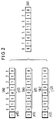
FIG 1 zeigt ein aus 3 Koppelfeldebenen SN₀, SN₁, SN₂ bestehendes Koppelfeld SN eines digitalen Kommunikationssystems. Dabei sind die Koppelfeldebenen SN₀, SN₁, SN₂ über Schnittstellenelemente S mit dem Kommunikationsnetz N verbunden. Die Schnittstellenelemente S enthalten Logikelemente A, A' sowie Logikelemente B, B'.FIG 1 shows a switching matrix SN consisting of 3 switching matrix levels SN₀, SN₁, SN₂ of a digital communication system. The switching network levels SN₀, SN₁, SN₂ are connected via interface elements S to the communication network N. The interface elements S contain logic elements A, A 'and logic elements B, B'.
Die Logikelemente A, A' enthalten Speicherelemente SP, Verteilermodule VM und Steuermodule SM. Ein über das Kommunikationsnetz N ankommendes Informationswort, das im Ausführungsbeispiel 8 Bit groß sein soll, wird in den Speicherelementen SP kurzfrisitig zwischengespeichert. Hier erfolgt die Bildung eines Paritybits. Anschließend wird das Informationswort zusammen mit dem Paritybit über die Verteilermodule VM auf die Koppelfeldebenen SN₀, SN₁, SN₂ aufgespaltet. Dieser Vorgang wird von den Steuermodulen SM gesteuert und überwacht.The logic elements A, A 'contain memory elements SP, distributor modules VM and control modules SM. An information word arriving via the communication network N, which is to be 8 bits in size in the exemplary embodiment, is temporarily stored in the memory elements SP. A parity bit is formed here. The information word is then split together with the parity bit via the distributor modules VM onto the switching network levels SN₀, SN₁, SN₂. This process is controlled and monitored by the control modules SM.
Nach dem Durchschaltevorgang über die jeweilige Koppelfeldebene SN₀, SN₁, SN₂ werden in den Logikelementen B, B' die durchgeschalteten Informationsworte auf während des Durchschaltevorgangs eventuell aufgetretene Bitfehler hin untersucht. Sie enthalten zu diesem Zweck Speicherelemente SP, Vergleicherelemente VGL, Steuerelemente ST, sowie Multiplexelemente MUX.After the switching process over the respective switching network level SN₀, SN₁, SN₂, the switched information words are examined in logic elements B, B 'for bit errors that may have occurred during the switching process. For this purpose, they contain memory elements SP, comparator elements VGL, control elements ST and multiplex elements MUX.
Die Speicherelemente SP führen je eine kurzfristige Zwischenspeicherung der durchgeschalteten Informationsworte durch, anschließend erfolgt eine bitweise Differenzbildung der separat durchgeschalteten Informationsworte durch die Vergleicherelemente VGL sowie eine erneute Paritybildung pro Informationswort und Koppelfeldebene; das Resultat dieser Paritybildung wird pro Koppelfeldebene mit dem mitübertragenen Paritybit verglichen. Dieser Vorgang wird von Steuerelementen ST gesteuert und überwacht.The memory elements SP each carry out a short-term temporary storage of the switched-through information words, followed by a bit-wise difference formation between the separately switched-through information words by the comparator elements VGL and a new parity formation for each information word and switching matrix level; the result of this parity formation is compared with the transmitted parity bit for each switching matrix level. This process is controlled and monitored by control elements ST.
Zur Bitfehlererkennung werden somit zum einen die über je eine Koppelfeldebene durchgeschalteten Informationsworte bitweise miteinander verglichen sowie zum anderen ein ausgangsseitiger Paritätstest der 3 durchgeschalteten Informationsworte durchgeführt. Das Ergebnis jener Bewertungen wird von statistischen Bewertungsprozeduren f(s) festgehalten. Somit lassen sich zu einem späteren Zeitpunkt (statistische) Aussagen über die Qualität der Durchschaltung über die jeweilige Koppelfeldebene SN₀, SN₁, SN₂ machen.For bit error detection, on the one hand, the information words that are switched through one switching matrix level are compared bit by bit, and on the other hand, an output-side parity test of the 3 information words that are switched through is carried out. The result of those evaluations is recorded by statistical evaluation procedures f (s). Thus, at a later point in time (statistical) statements about the quality of the connection through the respective switching network level SNebene, SN₁, SN₂ can be made.
Folgende Fallgestaltungen sind zu unterscheiden:
- 1.) Sind die beiden Informationsworte I(x), I(y), die über je zwei Koppelfeldebenen SNx, SNy geleitet wurden (


- 2.) Unterscheiden sich die beiden hinsichtlich ihrer jeweils mitübertragenen Parityinformationen konsistenten Informationsworte I(x), I(y), (


- 3.) Unterscheiden sich die beiden hinsichtlich ihrer jeweils mitübertragenen Parityinformation P konsistenten Informationsworte I(x), I(y) (


- 4.) In allen anderen Fällen wird das auszugebende Informationswort bitweise nach dem Prinzip des Majoritätsentscheid aus den 3 Informationsworten I(x), I(y), I(z) (x y
 x) gebildet und in Richtung Endteilnehmer weitergeleitet.
- 1.) Are the two information words I (x) , I (y) that were routed over two switching network levels SN x , SN y (
- 2.) Do the two information words I (x) , I (y) , (
- 3.) Do the two information words I (x) , I (y) (which are consistent in terms of their parity information P which are transmitted) differ
- 4.) In all other cases, the information word to be output is bit by bit according to the principle of the majority decision from the 3 information words I (x) , I (y) , I (z) (x yx) formed and forwarded towards the end participant.
Die Bewertungsprozeduren f(s) führen statistische Daten über die Qualität der Durchschaltevorgänge der drei Koppelfeldebenen SN₀, SN₁, SN₂. Diese statistischen Daten werden im Falle erkannter und eindeutig zuordenbarer Bitfehler aktualisiert. Somit wird im Zweifelsfall das Informationswort derjenigen Koppelfeldebene in Richtung Endteilnehmer weitergeleitet, die in der Vergangenheit die geringste Bitfehlerrate aufgewiesen hat. Eine besonders einfache Ausgestaltung der Erfindung liegt darin, daß nur die unter Punkt 1.) und 4.) genannten Fallgestaltungen berücksichtigt werden; dies bedeutet, daß keine statische Funktion f(s) definiert ist.
In den in FIG 2, FIG 3, FIG 4 dargestellten Ausführungsbeispielen wird davon ausgegangen, daß das Informationswort die Länge 8 Bit besitzt und mit der invertierten binären Quersumme als Prüfinformation gesichert ist.The evaluation procedures f (s) carry statistical data on the quality of the switching operations of the three switching network levels SN₀, SN₁, SN₂. This statistical data is updated in the event of identified and clearly assignable bit errors. In case of doubt, the information word of the switching matrix level is forwarded towards the end user that has had the lowest bit error rate in the past. A particularly simple embodiment of the invention resides in the fact that only the case configurations mentioned under
In the exemplary embodiments shown in FIG. 2, FIG. 3, FIG. 4, it is assumed that the information word the length is 8 bits and is saved with the inverted binary checksum as test information.
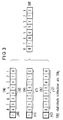
Im in FIG 2 dargestellten Ausführungsbeispiel wird davon ausgegangen, daß jeweils Bit 4 der über die Koppelfeldebenen SN₁ und SN₂ geleiteten Informationsworte I(1) und I(2) verfälscht wurde. Nach dem erfindungsgemäßen Verfahren wird das Informationswort I(o) weitergeleitet, da hier Paritykonsistenz vorhanden ist. Zwar stimmen die Informationsworte I(1), I(2) überein, beide sind allerdings inkonsistent hinsichtlich ihrer mitübertragenen Parityinformation P.In the exemplary embodiment shown in FIG. 2, it is assumed that
Im in FIG 3 dargestellten Ausführungsbeispiel wird davon ausgegangen, daß Bit 4 der über die Koppelfeldebenen SN₁ und SN₂ geleiteten Informationsworte I(1) und I(2) verfälscht wurde, zusätzlich jedoch auch Bit 3 des Informationswortes I(2), wodurch I(2) konsistent hinsichtlich seiner mitübertragenen Parityinformation bleibt. Nach dem erfindungsgemäßen Verfahren erfolgt die Weiterleitung eines der hinsichtlich ihrer mitübertragenen Parityinformation P konsistenten Informationsworte I(0) oder I(2) in Abhängigkeit der statistischen Bewertungsprozeduren f(s). War insbesondere die Bitfehlerrate der Koppelfeldebene SN₂ in der betrachteten Vergangenheit größer als die der Koppelfeldebene SN₀, so erfolgt die Ausgabe des Informationswortes I(o) in Richtung Endteilnehmer.In the exemplary embodiment shown in FIG. 3, it is assumed that
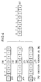
Im in FIG 4 dargestellten Ausführungsbeispiel wird davon ausgegangen, daß jeweils Bit 4 der über die Koppelfeldebenen SN₁ und SN₂ geleiteten Informationsworte I(1) und I(2) verfälscht wurde, zusätzlich jedoch auch das zu I(2) gehörige, mitübertragene Paritätsbit P(2), wodurch I(2) konsistent hinsichtlich seiner mitübertragenen Paritätsinformation bleibt. Nach dem erfindungsgemäßen Verfahren erfolgt die Weiterleitung eines der hinsichtlich ihrer mitübertragenen Parityinformation konsistenten Informationsworte I(o) oder I(2) in Abhängigkeit von der statistischen Bewertungsprozedur f(s). War insbesondere die Bitfehlerrate der Koppelfeldebenen SN₂ in der betrachteten Vergangenheit größer als die der Koppelfeldebene SN₀, so erfolgt die Ausgabe des Informationswortes I(o) in Richtung Endteilnehmer.In the illustrated in FIG 4 embodiment, it is assumed that each
Das erfindungsgemäße Verfahren ist in der Lage, Einfachfehler in dem Tripel der Informationsworte I(o), I(1), I(2) sicher zu korrigieren, da dies Eigenschaft des Prinzips des Majoritätsentscheides ist, welcher in solchen Fehlersituationen zur Anwendung kommt (vgl. Verfahrensbeschreibung Punkt 4).The method according to the invention is able to reliably correct single errors in the triple of information words I (o) , I (1) , I (2) , since this is the property of the principle of the majority decision, which is used in such error situations (cf. Process description point 4).
Aufgrund des Majoritätsentscheides in Verbindung mit Punkt 1) der Verfahrensbeschreibung lassen sich Doppelfehler in dem Tripel der Informationsworte I(o), I(1), I(2) ebenfalls sicher korrigieren. Hierdurch ergibt sich eine wesentliche Reduktion der in Richtung Endteilnehmer ausgegebenen Bitfehler, welche durch ausschließliche Verwendung des Prinzips des Majoritätsentscheides nicht erreichbar wäre.Due to the majority decision in connection with point 1) of the description of the method, double errors in the triple of information words I (o) , I (1) , I (2) can also be corrected reliably. This results in a significant reduction in the bit errors output in the direction of the end participant, which would not be achievable by exclusively using the principle of the majority decision.
Ebenfalls aufgrund des Majoritätsentscheides werden Dreifachfehler in dem Tripel der Informationsworte I(o), I(1), I(2), welche unterschiedliche Bitpositionen betreffen, sicher korrigiert. Ist das jeweils gleiche Bit aller 3 Informationsworte I(0), I(1), I(2) verfälscht, so erfolgt jedoch eine Falschausgabe. Bleibt aber im Falle eines Dreifachfehlers ein Informationswort unversehrt, so kann trotz der gleichzeitigen Verfälschung desselben Bits der beiden weiteren Informationsworte durch Zuhilfenahme der statistischen Bewertungsprozeduren f(s) gemäß Punkt 2.) und 3.) der Verfahrensbeschreibung das wahrscheinlich korrekte Informationswort ausgegeben werden. Dies gestattet die weitere Reduzierung der zum Endteilnehmer ausgegebenen Bitfehler, insbesondere im Fall von Koppelfeldebenen mit stark unterschiedlicher Durchschaltungsqualität.Also on the basis of the majority decision, triple errors in the triple of information words I (o) , I (1) , I (2) , which relate to different bit positions, are reliably corrected. If the same bit of all 3 information words I (0) , I (1) , I (2) is falsified, an incorrect output occurs. However, if an information word remains intact in the event of a triple error, the probably correct information word can be output despite the simultaneous falsification of the same bit of the two other information words by using the statistical evaluation procedures f (s) in accordance with
Die Logikelemente A, A', B, B' können vorzugsweise in einem hoch integrierten Baustein - ASIC-Baustein - implementiert sein. Solche Bausteine werden heute vielfältig eingesetzt; durch die Verwendung derartiger Bausteine wird auch sichergestellt, daß die bei der Abspeicherung und Bewertung der Informationsworte entstehenden Verzögerungszeiten minimiert werden und für die praktischen Überlegungen vernachlässigt werden können.The logic elements A, A ', B, B' can preferably be implemented in a highly integrated component - ASIC component. Such modules are used in a variety of ways today; The use of such modules also ensures that the delay times arising in the storage and evaluation of the information words are minimized and can be neglected for practical considerations.
Claims (4)
dadurch gekennzeichnet,
daß die ersten Elemente (A, A') das ankommende Informationswort, ergänzt durch die Prüfinformation (P) spiegelbildlich aufspalten und über jede Koppelfeldebene (SN₀, SN₁, SN₂) weiterleiten und die zweiten Elemente (B, B') jedes der durchgeschalteten Informationsworte bitweise miteinander vergleichen und entweder dasjenige Informationswort zum Endteilnehmer weiterleiten,
das sich aufgrund eines bitweise durchzuführenden Majoritätsentscheides aus den drei durchgeschalteten Informationsworten ergibt.
characterized,
that the first elements (A, A ') split the incoming information word, supplemented by the test information (P) in mirror image and forward them over each switching matrix level (SN₀, SN₁, SN₂) and the second elements (B, B') of each of the connected information words bit by bit compare with each other and either forward the information word to the end participant,
that results from the three information words that have been switched through based on a bit-by-bit majority decision.
dadurch gekennzeichnet,
daß die ersten Elemente (A, A') das ankommende Informationswort, ergänzt durch die Prüfinformation (P) spiegelbildlich aufspalten und über jede Koppelfeldebene (SN₀, SN₁, SN₂) weiterleiten und die zweiten Elemente (B, B') jedes der durchgeschalteten Informationsworte bitweise miteinander vergleichen und entweder dasjenige Informationswort zum Endteilnehmer weiterleiten,
characterized,
that the first elements (A, A ') split the incoming information word, supplemented by the test information (P) in mirror image and forward them over each switching matrix level (SN₀, SN₁, SN₂) and the second elements (B, B') of each of the connected information words bit by bit compare with each other and either forward the information word to the end participant,
dadurch gekennzeichnet,
daß die Prüfinformation (P) die Parität des Informationswortes ist.The method of claims 1 and 2
characterized,
that the check information (P) is the parity of the information word.
dadurch gekennzeichnet,
daß die ersten Elemente (A, A') erste Logikelemente sind, die aus
characterized,
that the first elements (A, A ') are first logic elements that consist of
Applications Claiming Priority (2)
| Application Number | Priority Date | Filing Date | Title |
|---|---|---|---|
| DE4132552 | 1991-09-30 | ||
| DE4132552A DE4132552C1 (en) | 1991-09-30 | 1991-09-30 |
Publications (1)
| Publication Number | Publication Date |
|---|---|
| EP0535396A1 true EP0535396A1 (en) | 1993-04-07 |
Family
ID=6441825
Family Applications (1)
| Application Number | Title | Priority Date | Filing Date |
|---|---|---|---|
| EP92115202A Ceased EP0535396A1 (en) | 1991-09-30 | 1992-09-04 | Method for the reduction of bit errors in a digital communication system |
Country Status (3)
| Country | Link |
|---|---|
| US (1) | US5436915A (en) |
| EP (1) | EP0535396A1 (en) |
| DE (1) | DE4132552C1 (en) |
Cited By (2)
| Publication number | Priority date | Publication date | Assignee | Title |
|---|---|---|---|---|
| EP0582848A2 (en) * | 1992-08-11 | 1994-02-16 | Siemens Aktiengesellschaft | Method of error detection in digital communication systems |
| FR2737371A1 (en) * | 1995-07-26 | 1997-01-31 | Trt Telecom Radio Electr | SECURITY BY DOUBLING AT LEAST CERTAIN LOGIC CHANNELS IN A TELECOMMUNICATIONS NETWORK |
Families Citing this family (7)
| Publication number | Priority date | Publication date | Assignee | Title |
|---|---|---|---|---|
| KR100220570B1 (en) * | 1995-03-16 | 1999-09-15 | 김영환 | Error detection apparatus of packet exchanger |
| EP0999669A1 (en) * | 1998-11-06 | 2000-05-10 | Nortel Matra Cellular | Method and apparatus for diversity reception of user messages with different forward error correction |
| DE60211089T2 (en) * | 2001-09-27 | 2006-11-23 | Alcatel Canada Inc., Ottawa | System and method for selecting data sources for a network element with redundant sources |
| CA2357931A1 (en) * | 2001-09-27 | 2003-03-27 | Alcatel Canada Inc. | System and method of selecting sources for a network element having redundant sources |
| US7127669B2 (en) * | 2002-05-31 | 2006-10-24 | Kiribati Wireless Ventures, Llc | Redundant path communication methods and systems |
| US9424937B2 (en) * | 2013-02-25 | 2016-08-23 | U.S. Department Of Energy | Method for programming a flash memory |
| CN112073434B (en) * | 2020-09-28 | 2022-06-07 | 山东产研集成电路产业研究院有限公司 | Method for reducing TOE-based transmission delay of receiving channel of high-frequency transaction terminal |
Citations (7)
| Publication number | Priority date | Publication date | Assignee | Title |
|---|---|---|---|---|
| DE2718317A1 (en) * | 1977-04-25 | 1978-11-02 | Gen Electric Co Ltd | Telephony digital switching network - has error-code generator at each receive interface responding to received data packets and connected to two TDM switching matrices |
| WO1985001410A1 (en) * | 1983-09-12 | 1985-03-28 | Western Electric Company, Inc. | Duplicated time division switching system |
| WO1988003738A1 (en) * | 1986-11-06 | 1988-05-19 | Telefonaktiebolaget L M Ericsson | Method and digital switching networks for fault supervision |
| EP0321426A1 (en) * | 1987-12-18 | 1989-06-21 | Telefonaktiebolaget L M Ericsson | An error correction method in a switch and a switch provided with error correction means |
| EP0325318A2 (en) * | 1988-01-16 | 1989-07-26 | Philips Patentverwaltung GmbH | Switching exchange |
| EP0381104A1 (en) * | 1989-02-02 | 1990-08-08 | Alcatel Cit | Device for the connection of a central connection chain to connection units |
| EP0403451A1 (en) * | 1989-06-16 | 1990-12-19 | Telefonaktiebolaget L M Ericsson | A method and arrangement for detecting and localizing errors or faults in a multi-plane unit incorporated in a digital time switch |
Family Cites Families (3)
| Publication number | Priority date | Publication date | Assignee | Title |
|---|---|---|---|---|
| FR2233780B1 (en) * | 1973-06-13 | 1977-05-06 | Materiel Telephonique | |
| DE3821871A1 (en) * | 1988-06-29 | 1990-01-18 | Philips Patentverwaltung | Broadband coupling device |
| US5084878A (en) * | 1988-10-24 | 1992-01-28 | Hitachi, Ltd. | Fault tolerant system employing majority voting |
-
1991
- 1991-09-30 DE DE4132552A patent/DE4132552C1/de not_active Expired - Fee Related
-
1992
- 1992-09-04 EP EP92115202A patent/EP0535396A1/en not_active Ceased
- 1992-09-30 US US07/953,223 patent/US5436915A/en not_active Expired - Fee Related
Patent Citations (7)
| Publication number | Priority date | Publication date | Assignee | Title |
|---|---|---|---|---|
| DE2718317A1 (en) * | 1977-04-25 | 1978-11-02 | Gen Electric Co Ltd | Telephony digital switching network - has error-code generator at each receive interface responding to received data packets and connected to two TDM switching matrices |
| WO1985001410A1 (en) * | 1983-09-12 | 1985-03-28 | Western Electric Company, Inc. | Duplicated time division switching system |
| WO1988003738A1 (en) * | 1986-11-06 | 1988-05-19 | Telefonaktiebolaget L M Ericsson | Method and digital switching networks for fault supervision |
| EP0321426A1 (en) * | 1987-12-18 | 1989-06-21 | Telefonaktiebolaget L M Ericsson | An error correction method in a switch and a switch provided with error correction means |
| EP0325318A2 (en) * | 1988-01-16 | 1989-07-26 | Philips Patentverwaltung GmbH | Switching exchange |
| EP0381104A1 (en) * | 1989-02-02 | 1990-08-08 | Alcatel Cit | Device for the connection of a central connection chain to connection units |
| EP0403451A1 (en) * | 1989-06-16 | 1990-12-19 | Telefonaktiebolaget L M Ericsson | A method and arrangement for detecting and localizing errors or faults in a multi-plane unit incorporated in a digital time switch |
Non-Patent Citations (1)
| Title |
|---|
| PATENT ABSTRACTS OF JAPAN vol. 009, no. 123 (E-317)28. Mai 1985 & JP-A-60 010 996 ( MATSUSHITA ) 21. Januar 1985 * |
Cited By (5)
| Publication number | Priority date | Publication date | Assignee | Title |
|---|---|---|---|---|
| EP0582848A2 (en) * | 1992-08-11 | 1994-02-16 | Siemens Aktiengesellschaft | Method of error detection in digital communication systems |
| EP0582848A3 (en) * | 1992-08-11 | 1995-06-21 | Siemens Ag | Method of error detection in digital communication systems. |
| FR2737371A1 (en) * | 1995-07-26 | 1997-01-31 | Trt Telecom Radio Electr | SECURITY BY DOUBLING AT LEAST CERTAIN LOGIC CHANNELS IN A TELECOMMUNICATIONS NETWORK |
| EP0757504A1 (en) * | 1995-07-26 | 1997-02-05 | Philips Communication D'entreprise | Securing by duplication of virtual circuits in a telecommunications network |
| US6580690B1 (en) | 1995-07-26 | 2003-06-17 | Koninklijke Philips Electronics N.V. | Security by doubling at least certain logic paths in a telecommunications network |
Also Published As
| Publication number | Publication date |
|---|---|
| US5436915A (en) | 1995-07-25 |
| DE4132552C1 (en) | 1992-11-12 |
Similar Documents
| Publication | Publication Date | Title |
|---|---|---|
| DE4128412C1 (en) | ||
| EP0645913A2 (en) | Method and apparatus for the transmission of ATM cells over virtual paths | |
| EP0645918A2 (en) | Method and circuit arrangement for transmitting of message cells through redundant virtual path pairs of a ATM-communication network | |
| EP0698980A2 (en) | Serial bus system | |
| EP0219917B1 (en) | Switching device with fault correction | |
| DE3614062A1 (en) | METHOD FOR FLOW CONTROLLING DATA WITHIN A MESHED NETWORK | |
| WO2006128400A1 (en) | Method for transmitting data for controlling an hvdct system | |
| DE4132552C1 (en) | ||
| EP0325318B1 (en) | Switching exchange | |
| DE4226599C2 (en) | Error detection method in digital communication systems | |
| DE4121481C1 (en) | ||
| DE4218054C1 (en) | Process monitoring and bit error reduction for switched connections in digital communication systems | |
| DE69913152T2 (en) | Replace special characters in a data stream | |
| EP2388937B1 (en) | Method for transmitting a digital signal in inverse multiplex, in particular over an optical transport network and receiver device for a system for realising the method | |
| DE3219923A1 (en) | SIGNAL SYSTEM WITH SIMILAR REDUNDANCY SIGNALS | |
| EP0999675B1 (en) | Line fault detecting circuit for electrical data transmission system | |
| EP0353660B1 (en) | Fault prevention method in memory systems of data-processing installations, in particular telephone exchanges | |
| DE2915113A1 (en) | BUS DEVICE FOR A DATA PROCESSING SYSTEM | |
| EP0402741B1 (en) | Method and circuit arrangement for forwarding cells transmitted in an asynchronous transfer mode | |
| WO1993000760A1 (en) | Process for determining the origin of bit errors | |
| DE19626064A1 (en) | Device for correcting faults in monitoring block for master position in optical TV cable | |
| DE4121480C1 (en) | ||
| EP1680895A2 (en) | Unit of the transmission of data in a serial bidirectional bus | |
| DE69631366T2 (en) | Method and device for correcting transmission errors and detecting errors during the transmission of data via a data transmission medium | |
| DE19836254A1 (en) | Activation and deactivation of source and drain of tandem connection in telecommunications network for testing quality of data in specific transmission section |
Legal Events
| Date | Code | Title | Description |
|---|---|---|---|
| PUAI | Public reference made under article 153(3) epc to a published international application that has entered the european phase |
Free format text: ORIGINAL CODE: 0009012 |
|
| AK | Designated contracting states |
Kind code of ref document: A1 Designated state(s): CH DE FR GB IT LI SE |
|
| 17P | Request for examination filed |
Effective date: 19930422 |
|
| 17Q | First examination report despatched |
Effective date: 19960917 |
|
| GRAG | Despatch of communication of intention to grant |
Free format text: ORIGINAL CODE: EPIDOS AGRA |
|
| STAA | Information on the status of an ep patent application or granted ep patent |
Free format text: STATUS: THE APPLICATION HAS BEEN REFUSED |
|
| 18R | Application refused |
Effective date: 19981119 |