EP0219917B1 - Switching device with fault correction - Google Patents
Switching device with fault correction Download PDFInfo
- Publication number
- EP0219917B1 EP0219917B1 EP86201819A EP86201819A EP0219917B1 EP 0219917 B1 EP0219917 B1 EP 0219917B1 EP 86201819 A EP86201819 A EP 86201819A EP 86201819 A EP86201819 A EP 86201819A EP 0219917 B1 EP0219917 B1 EP 0219917B1
- Authority
- EP
- European Patent Office
- Prior art keywords
- sub
- switching
- data
- error
- decoder
- Prior art date
- Legal status (The legal status is an assumption and is not a legal conclusion. Google has not performed a legal analysis and makes no representation as to the accuracy of the status listed.)
- Expired - Lifetime
Links
Images


Classifications
-
- H—ELECTRICITY
- H04—ELECTRIC COMMUNICATION TECHNIQUE
- H04Q—SELECTING
- H04Q11/00—Selecting arrangements for multiplex systems
- H04Q11/04—Selecting arrangements for multiplex systems for time-division multiplexing
Landscapes
- Engineering & Computer Science (AREA)
- Computer Networks & Wireless Communication (AREA)
- Detection And Prevention Of Errors In Transmission (AREA)
- Monitoring And Testing Of Exchanges (AREA)
- Use Of Switch Circuits For Exchanges And Methods Of Control Of Multiplex Exchanges (AREA)
Description
Die Erfindung betrifft eine Vermittlungsanlage zur rechnergesteuerten Vermittlung einer Vielzahl von Leitungen, von denen jede digitale zeitverschachtelte Daten führt, über ein Koppelfeld, das die Daten in Form von mehrere Datenbits umfassenden Datenwörtern parallel überträgt.The invention relates to a switching system for computer-controlled switching of a plurality of lines, each of which carries digital time-interleaved data, via a switching matrix that transmits the data in the form of data words comprising several data bits in parallel.
Derartige Vermittlungsanlagen, bei denen insbesondere die Koppelfelder verschiedenen Aufbau haben, sind allgemein bekannt und dienen für die Vermittlung einer großen Anzahl von Teilnehmerstellen. Da ein fehlerbedingter Ausfall einer derartigen Vermittlungsanlage eine große Anzahl von Teilnehmern betrifft, werden hohe Anforderungen an die Zuverlässigkeit derartiger Vermittlungsanlagen gestellt, insbesondere an die Rechner für die Erzeugung der Steuerdaten zur Einstellung der Koppelfelder, denn ein Fehler in diesem Steuerrechner kann die gesamte Vermittlungsanlage ausfallen lassen. Es ist daher üblich, zumindest die Steuerrechner für Vermittlungsanlagen doppelt oder dreifach vorzusehen, wie beispielsweise aus der Zeitschrift "Philips Technical Review" Vol. 41, Nr. 1983/84, Nr. 1, Seiten 1 bis 11 hervorgeht. Darin ist auch erläutert, wie es durch ein spezielles Fehlersicherungskonzept erreicht werden kann, daß einer von mehreren Rechnern ausfallen kann, ohne daß die gesamte Vermittlungsanlage zusammenbricht.Switching systems of this type, in which the switching networks in particular have different structures, are generally known and are used for switching a large number of subscriber stations. Since a failure-related failure of such a switching system affects a large number of subscribers, high demands are placed on the reliability of such switching systems, in particular on the computers for generating the control data for setting the switching networks, since an error in this control computer can cause the entire switching system to fail . It is therefore customary to provide at least the control computer for switching systems twice or three times, as can be seen, for example, from the magazine "Philips Technical Review" Vol. 41, No. 1983/84, No. 1, pages 1 to 11. It also explains how a special error protection concept can ensure that one of several computers can fail without the entire switching system collapsing.
In allen Konzepten wird jedoch keine Fehlersicherung der eigentlichen Koppelfelder verwendet, da davon ausgegangen wird, daß beispielsweise ein defektes Bauelement nur einen vermittelten Weg, d.h. die zwei beteiligten Teilnehmer betrifft, wobei bestimmte Konzepte von Koppelfeldern erlauben würden, eine bestehende Verbindung umzuschalten, so daß die defekte Stelle umgangen wird, wenn der Fehler festgestellt ist. Zum Feststellen eines Fehlers in einer neu aufgebauten Verbindung ist es üblich, vor den zu übertragenden Daten bestimmte Prüfdaten über die Verbindung zu senden und am Ende der Verbindung zu prüfen, ob diese richtig eintreffen. Ein derartiges Verfahren ist jedoch nicht nur zeitraubend, sondern in vielen Arten von Koppelfeldern bzw. bei manchen Fehlerstellen ist es nicht möglich, einen Weg zu vermitteln, der die fehlerhafte Stelle umgeht, und außerdem können Fehler, die während des Bestehens eines vermittelten Weges auftreten, nicht ohne weiteres festgestellt werden. Insbesondere bei der Übertragung von Daten kann dies erhebliche Auswirkungen haben.In all concepts, however, no error protection of the actual switching matrixes is used, since it is assumed that a defective component, for example, only one mediated route, ie concerns the two participants involved, whereby certain concepts of switching networks would allow an existing connection to be switched over so that the defective location is bypassed when the fault is ascertained. To determine an error in a newly established connection, it is customary to send certain test data over the connection before the data to be transmitted and to check at the end of the connection whether it arrives correctly. However, such a method is not only time-consuming, but in many types of switching matrixes or in the case of some fault locations it is not possible to mediate a path that bypasses the faulty location, and furthermore errors that occur during the existence of a mediated path can cannot be easily determined. This can have considerable effects, especially when data is being transferred.
Es ist zwar bekannt, zu übertragende Daten durch Hinzufügen von redundanten Bits, die auf verschiedene Weise gewonnen sein können, oder durch vollständige Umcodierung zu sichern, wobei je nach der Menge der zugefügten redundanten Bits eine mehr oder weniger umfangreiche Wiederherstellung von verfälschten Datenwörtern und in jedem Falle eine umfangreichere Erkennung falscher Datenwörter, die nicht wiederhergestellt werden können, möglich ist. Im Falle eines aufgetretenen und erkannten Fehlers ist jedoch die Reparatur äußerst schwierig, da eine Vermittlungsanlage niemals abgeschaltet werden kann.Although it is known to secure data to be transmitted by adding redundant bits, which can be obtained in different ways, or by completely transcoding, a more or less extensive recovery of corrupted data words and in each of them, depending on the amount of redundant bits added If a more extensive detection of incorrect data words that cannot be recovered is possible. In the event of an error that has occurred and been identified, however, the repair is extremely difficult since a switching system can never be switched off.
Aufgabe der Erfindung ist es, eine Vermittlungsanlage der eingangs genannten Art anzugeben, bei der die zu vermittelnden Daten derart fehlergesichert über das Koppelfeld übertragen werden, daß bei Defekten insbesondere im Koppelfeld bis zu einem gewissen Umfang verfälschte Datenwörter wiederhergestellt und weiter verfälschte Datenwörter erkannt werden können und eine Reparatur von defekten Teilen auf einfache Weise ohne Abschalten der Vermittlungsanlage möglich ist.The object of the invention is to provide a switching system of the type mentioned at the outset, in which the data to be transferred are transmitted in such a way that they are error-protected via the switching matrix that to a certain extent in the case of defects, in particular in the switching matrix falsified data words can be recovered and further falsified data words can be recognized and defective parts can be repaired in a simple manner without switching off the switching system.
Diese Aufgabe wird erfindungsgemäß dadurch gelöst, daß dem Koppelfeld ein Codierer vorgeschaltet ist, der aus jedem Datenwort ein Codewort mit einer Anzahl Codebits, die größer als die Anzahl Datenbits je Datenwort ist, erzeugt und dem Koppelfeld zuführt, das in eine Anzahl paralleler Teilkoppelfelder zur Übertragung jeweils eines Teilcodewortes, bestehend aus einem Teil der Codebits, aufgeteilt ist, und daß dem Koppelfeld ein Decoder nachgeschaltet ist, der aus allen Teilcodewörtern die ursprünglichen Datenwörter erzeugt, wobei die Codewörter und die Teilcodewörter in an sich bekannter Weise derart aufgebaut sind, daß bei mindestens einem verfälschten Teilcodewort der Decoder die richtigen Datenwörter und ein das verfälschte Teilcodewort anzeigendes Fehlersignal erzeugt.This object is achieved in that the switch is preceded by an encoder which generates a code word with a number of code bits, which is greater than the number of data bits per data word, from each data word and feeds it to the switch, which transmits into a number of parallel sub-switches each a sub-code word, consisting of a part of the code bits, is divided, and that the coupling field is followed by a decoder that generates the original data words from all the sub-code words, the code words and the sub-code words being constructed in a manner known per se such that at least an incorrect partial code word of the decoder generates the correct data words and an error signal indicating the incorrect partial code word.
Die Erfindung benutzt die Codierregeln, die in der bereits genannten Druckschrift angegeben sind, in einer besonderen Weise für die Fehlersicherung der zu vermittelten Daten selbst. Dadurch treten in den vermittelnden Daten Fehler innerhalb nur eines Teilkoppelfeldes nicht in Erscheinung, sie werden jedoch erkannt. Eine Erkennung erfolgt auch dann, wenn mehr als ein Teilkoppelfeld für denselben vermittelnden Weg fehlerhaft ist, wobei dann die Datenwörter allerdings nicht mehr wiederhergestellt werden können. Ein gleichzeitiges Auftreten mehrerer Fehler ist jedoch sehr unwahrscheinlich. Die Fehlerüberwachung kann während des Betriebes, d.h. nach dem Aufbau eines vermittelnden Weges, ständig erfolgen, so daß das Wegeprüfen vor dem Durchschalten einer Verbindung entfällt.The invention uses the coding rules, which are specified in the publication already mentioned, in a special way for error protection of the data to be conveyed itself. As a result, errors within only a sub-switching matrix do not appear in the communicating data, but they are recognized. A detection also takes place if more than one sub-switching matrix is faulty for the same switching path, but the data words can then no longer be restored. However, a simultaneous occurrence of several errors is very unlikely. Fault monitoring can be carried out continuously during operation, ie after the establishment of an intermediary route, so that route checking before a connection is switched through is not necessary.
Wenn ein Defekt in einem Teilkoppelfeld aufgetreten ist, kann dieses leicht während des Betriebes ausgetauscht werden, da mit den übrigen Teilkoppelfeldern die Wiederherstellung der übertragenen Datenwörter richtig möglich ist. Dadurch braucht die Vermittlungsanlage für Reparaturzwecke nicht ausgeschaltet zu werden.If a defect has occurred in a sub-switching network, this can easily be replaced during operation, since the rest of the sub-switching networks can be used to correctly restore the transmitted data words. As a result, the switching system does not need to be switched off for repair purposes.
Eine günstige Codierung besteht darin, daß die Anzahl der Codebits je Codewort doppelt so groß ist wie die Anzahl der Datenbits je Datenwort. Dies stellt einen guten Kompromiß zwischen dem im Koppelfeld zusätzlich erforderlichen Aufwand und den Möglichkeiten zur Fehlerkorrektur dar.A favorable coding is that the number of code bits per code word is twice as large as the number of data bits per data word. This represents a good compromise between the additional effort required in the switching matrix and the possibilities for error correction.
Die Steuerung der Koppelfelder erfolgt durch einen zentralen Vermittlungsrechner, der insbesondere aufgrund der Signalisierungsdaten den durchzuschaltenden Weg bestimmt. Häufig werden die vom Vermittlungsrechner erzeugten Signale, die den durchzuschaltenden Weg angeben, einem dem Koppelfeld direkt zugeordneten Einstellrechner zugeführt, der aufgrund dieser Signale die Durchschaltung des Weges, beispielsweise die Ansteuerung der einzelnen Koppelpunkte, durchführt. Eine Ausgestaltung der Erfindung für eine derartige Vermittlungsanlage ist dadurch gekennzeichnet, daß jedem Teilkoppelfeld ein eigener, vorzugsweise fehlergesicherter Einstellrechner zugeordnet ist und alle Einstellrechner parallel von einem vorzugsweise fehlergesicherten zentralen Vermittlungsrechner gesteuert sind. Auf diese Weise wird verhindert, daß ein Fehler in einem Einstellrechner zu einem Zusammenbruch der Vermittlungsanlage führt, da ein defekter Einstellrechner, der in einem Teilkoppelfeld einen falschen Weg schaltet, für den dem Koppelfeld nachgeschalteten Decoder wie ein Fehler in einem Teilkoppelfeld wirkt, der erkennbar und korrigierbar ist. Die Wahrscheinlichkeit für Fehlvermittlungen ist vernachlässigbar klein, weil mindestens eine bestimmte Anzahl Einstellrechner identische Fehler machen müßten. Wenn der Einstellrechner in einer Baugruppe mit dem zugehörigen Teilkoppelfeld zusammengefaßt ist, kann während des Betriebs die gesamte Baugruppe ausgetauscht werden. Diese verursacht zwar zunächst Fehlverbindungen, da der Einstellrechner noch nicht mit den gesamten Daten für die Vermittlung aller Wege geladen ist, jedoch wirkt dies wie ein Fehler im Teilkoppelfeld, der im Decoder korrigierbar ist. Da Verbindungen aber nur begrenzte Zeit bestehen und laufend neue Verbindungen aufgebaut werden, deren Einstelldaten der Einstellrechner dann ebenfalls erhält, werden die von einer ausgewechselten Baugruppe zunächst erzeugten falschen Datenwörter zunehmend weniger, bis schließlich nur noch solche Wege aktiv sind, die nach dem Austausch vermittelt wurden. Ein Datenaustausch der Einstellrechner untereinander ist somit nicht erforderlich, und es ergeben sich auch keine Synchronisationsprobleme.The switching networks are controlled by a central switching computer, which determines the path to be switched through, in particular on the basis of the signaling data. Frequently, the signals generated by the switching computer, which indicate the path to be switched through, are fed to a switching computer which is directly assigned to the switching matrix and which, based on these signals, carries out the switching of the path, for example the control of the individual switching points. An embodiment of the invention for such a switching system is characterized in that each sub-switching network is assigned its own, preferably error-protected, setting computer and all setting computers are controlled in parallel by a preferably error-protected central switching computer. In this way, it is prevented that an error in a setting computer leads to a breakdown of the switching system, since a defective setting computer which switches the wrong way in a sub-switching network acts as an error in a sub-switching network for the decoder downstream, which is recognizable and is correctable. The likelihood of miscarriage is negligibly small because at least a certain number of setting computers would have to make identical mistakes. If the setting computer is combined in a module with the associated sub-switching matrix, the entire module can be replaced during operation. This initially causes incorrect connections, since the setting computer is not yet loaded with the entire data for switching all paths, but this acts like an error in the partial switching matrix, which can be corrected in the decoder. However, since connections only exist for a limited time and new connections are constantly being set up, the setting data of which are then also received by the setting computer, the incorrect data words initially generated by a replaced module become increasingly fewer, until finally only those paths are active that were mediated after the exchange . Data exchange between the setting computers is therefore not necessary, and there are no synchronization problems.
Der zusätzliche Aufwand für die fehlergesicherte Übertragung der Daten innerhalb der Vermittlungsanlage gemäß der Erfindung besteht außer dem zusätzlichen Umfang des Koppelfeldes auch in dem Codierer und dem Decoder. Besonders der letztere muß einen relativ großen Umfang haben, da die Anzahl der Codebits größer ist als die Anzahl der Datenbits. Um diesen Umfang zu verringern, ist es nach einer weiteren Ausgestaltung der Erfindung zweckmäßig, daß der dem Koppelfeld vorgeschaltete Codierer aus mindestens zwei Teilcodierern besteht, von denen jeder einen anderen Teil des Datenwortes empfängt und ein Untercodewort erzeugt, daß jedes Teilkoppelfeld ein Teilcodewort aus jeweils einem anderen Teil der Codebits mindestens einiger Untercodewörter überträgt, so daß alle Teilkoppelfelder alle Untercodewörter übertragen, und daß der dem Koppelfeld nachgeschaltete Decoder aus einer der Anzahl Teilcodierern gleichen Anzahl Teildecodern besteht, die derart mit den Ausgängen des Koppelfeldes verbunden sind, daß jeder Teildecoder jeweils alle Codebits eines Untercodewortes erhält und den entsprechenden Teil des Datenwortes erzeugt. Dabei können die Teilcodierer die Teildecoder je untereinander gleich aufgebaut sein. Es ist jedoch auch möglich, keine physikalisch getrennten Teilcodierer zu verwenden, sondern den Codierer so aufzubauen, daß die entsprechenden Teilcodewörter entnommen werden können. Die Aufteilung des Decoders in mehrere Teildecoder führt jedoch zu einem erheblich verringerten Gesamtaufwand, wie später erläutert wird, wobei die Möglichkeit, fehlerhafte Teilcodewörter zu korrigieren bzw. zu erkennen, bei normaler Fehlerwahrscheinlichkeit nur geringfügig verschlechtert wird. Dadurch, daß jedes Teilkoppelfeld einen anderen Teil der Codebits mindestens einiger Unter-codewörter überträgt, wirkt sich ein einzelnes defektes Teilkoppelfeld nur so aus, daß jeder Teildecoder zwar ein verfälschtes, jedoch korrigierbares Untercodewort erhält und damit das gesamte Datenwort dennoch richtig wiederherstellen kann.In addition to the additional scope of the switching matrix, the additional effort for the error-protected transmission of the data within the switching system according to the invention also consists in the encoder and the decoder. The latter in particular must have a relatively large scope, since the number of code bits is greater than the number of data bits. In order to reduce this scope, it is expedient according to a further embodiment of the invention that the encoder upstream of the switching matrix consists of at least two partial coders, each of which receives a different part of the data word and generates a subcode word, so that each partial switching matrix has a partial code word from one each transmits another part of the code bits of at least some sub-code words so that all sub-matrixes transmit all sub-code words, and that the decoder connected downstream of the switching network consists of a number of partial encoders equal to the number of partial decoders which are connected to the outputs of the switching network in such a way that each partial decoder receives all code bits of a subcode word and generates the corresponding part of the data word. The partial encoders, the partial decoders can each be constructed identically to one another. However, it is also possible not to use physically separate sub-encoders, but to construct the encoder in such a way that the corresponding sub-code words can be extracted. The division of the decoder into several partial decoders, however, leads to a considerably reduced overall expenditure, as will be explained later, the possibility of correcting or recognizing incorrect partial code words being only slightly deteriorated with a normal probability of error. Because each sub-matrix transmits a different part of the code bits of at least some sub-code words, a single defective sub-matrix only has the effect that each sub-decoder receives a corrupted, but correctable sub-code word and can therefore correctly restore the entire data word.
Bei der Decodierung der Codewörter kann die weitaus größte Anzahl fehlerhafter Codewörter wenn nicht korrigiert, so doch als fehlerhaft erkannt werden, wobei der Decoder ein entsprechendes Fehlersignal abgibt, das auch mehrere Bits umfassen kann, um verschiedene Fehler voneinander zu unterscheiden. Bei der eingangs genannten Druckschrift werden die Fehlersignale des Decoders von dem jeweils zugeordneten Rechner ausgewertet. Bei entsprechender Anwendung dieses Prinzips bei der vorliegenden Erfindung ist eine weitere Ausgestaltung dadurch gekennzeichnet, daß ein dem Decoder zugeordneter Fehlerspeicher mit den Fehlersignalausgängen des Decoders und mit einer den Vermittlungsweg durch das Koppelfeld anzeigenden Einrichtung, insbesondere einem die Datenwörter innerhalb eines Rahmens zählenden Zählers, verbunden ist, daß beim Auftreten eines Fehlersignals dieses und die Anzeige des Vermittlungsweges im Fehlerspeicher gespeichert und ein entsprechendes Signal an einen Überwachungsrechner übersandt wird, und daß der Überwachungsrechner über einen Datenbus den Inhalt des Fehlerspeichers abruft und diesen löscht. Auf diese Weise kann der Überwachungsrechner im wesentlichen unabhängig von den Fehlermeldungen arbeiten, wobei auch der Fall zugelassen werden kann, daß nach dem Auftreten eines Fehlersignals und dessen Abfrage durch den Überwachungsrechner noch weitere Fehlersignale auftreten, die dann nicht gespeichert werden. Wenn jedoch ein dauerhafter Defekt in einem Teilkoppelfeld vorliegt, werden die dadurch erzeugten Fehlersignale periodisch auftreten, so daß bei mehreren Defekten jeder Fehler irgenwann einmal erfaßt wird. Es ist jedoch auch möglich, daß der Fehlerspeicher die Signale mehrerer nacheinander auftretender Codewortfehler speichert und der Überwachungsrechner nur die jeweils abgerufenen Signale der gespeicherten Fehler löscht. Dabei kann der Fehlerspeicher als sogenannter FIFO aufgebaut sein, so daß der Überwachungsrechner bei einem Zugriff zum Abrufen der gespeicherten Fehlersignale mehrere davon abruft, jedoch nicht notwendigerweise alle, die momentan gespeichert sind.When the code words are decoded, the by far largest number of incorrect code words can, if not corrected, be recognized as incorrect, the decoder emitting a corresponding error signal, which can also comprise several bits, in order to distinguish different errors from one another. In the publication mentioned at the outset, the error signals of the decoder are evaluated by the respectively assigned computer. With appropriate application of this principle in the present invention, a further embodiment is characterized in that an error memory assigned to the decoder with the error signal outputs of the decoder and with a the switching path through the switching matrix indicating device, in particular a counter counting the data words within a frame, is connected such that when an error signal occurs, this and the display of the switching path are stored in the error memory and a corresponding signal is sent to a monitoring computer, and that the monitoring computer via a data bus retrieves the contents of the error memory and clears it. In this way, the monitoring computer can operate essentially independently of the error messages, and the case can also be permitted that after the occurrence of an error signal and its query by the monitoring computer, further error signals occur which are then not stored. However, if there is a permanent defect in a sub-switching matrix, the error signals generated thereby will occur periodically, so that if there are several defects, each error will be detected at some point. However, it is also possible for the error memory to store the signals of a plurality of code word errors which occur in succession and for the monitoring computer to delete only the signals of the stored errors which have been called up in each case. In this case, the error memory can be constructed as a so-called FIFO, so that the monitoring computer retrieves several of them when accessing the stored error signals, but not necessarily all of them that are currently stored.
Ausführungsbeispiele der Erfindung werden nachstehend anhand der Zeichnung näher erläutert.Embodiments of the invention are explained below with reference to the drawing.
Es zeigen:
- Fig. 1 ein Blockschaltbild eines Teils einer Vermittlungsanlage mit Steuerrechnern und Aufteilung des Koppelfeldes in Teilkoppelfelder mit vorgeschaltetem Codierer und nachgeschaltetem Decoder,
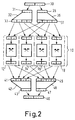
- Fig. 2 ein vereinfachtes schematischer Schaltbild von Codierer, Teilkoppelfeldern und Decoder zur Erläuterung der Aufteilung der Datenwörter,
- Fig. 3 ein Blockschaltbild der Behandlung der Fehlersignale, die vom Decoder bei fehlerhaft übertragenen Datenwörtern auftreten.
- 1 is a block diagram of part of a switching system with control computers and division of the switching matrix into partial switching matrixes with an upstream encoder and a downstream decoder,
- 2 shows a simplified schematic circuit diagram of encoder, sub-switching matrixes and decoder to explain the division of the data words,
- Fig. 3 is a block diagram of the handling of the error signals that occur from the decoder in the case of incorrectly transmitted data words.
In Fig. 1 ist ein Koppelfeld 10 einer Vermittlungsanlage dargestellt, das von einem Vermittlungsrechner 6 gesteuert wird. Diesem Koppelfeld 10 werden über eine Anzahl Eingänge, von denen hier nur der Eingang 1 beispielhaft dargestellt ist, digitale Datenwörter vorzugsweise bitparallel zugeführt, wobei jedem Eingang wie dem Eingang 1 eine Anzahl Kanäle von jeweils einem Teilnehmer zeitverschachtelt in Form aufeinanderfolgender Rahmen zugeführt werden.1 shows a
Die durchgeschalteten bzw. vermittelten Daten werden auf einer der Anzahl der Eingänge gleichen Anzahl Ausgänge abgegeben, von denen hier nur ein Ausgang 11 beispielhaft angegeben ist. Jeder Ausgang führt zeitverschachtelt die Datenwörter einer gleichen Anzahl Kanäle wie jeder Eingang, jedoch infolge der Vermittlung im Koppelfeld 10 andere Kanäle bzw. in anderer Reihenfolge. In einer vollständigen Vermittlungsanlage sind noch weitere Elemente vorhanden, beispielsweise Leitungsschaltungen für eingehende und ausgehende Leitungen sowie gegebenenfalls Multiplexer und Demultiplexer, die hier jedoch nicht dargestellt sind, da sie für die Erläuterung der Erfindung nicht von Bedeutung sind.The data which are switched through or transmitted are output on a number of outputs equal to the number of inputs, of which only one
Jeder Eingang des Koppelfeldes 10, wie der Eingang 1, führt auf einen Codierer 2, der aus jedem über den Eingang 1 zugeführte Datenwort ein Codewort erzeugt. Im vorliegenden Beispiel werde angenommen, daß jedes Datenwort acht Bit und jedes Codewort 16 Bit umfaßt. Die vom Codierer 2 erzeugten Codeworte werden in Teilcodeworte mit je vier Bit aufgeteilt, die über getrennte Verbindungen 3, 5, 7 und 9 auf je ein Teilkoppelfeld 12, 14, 16 und 18 führen. Jedes Teilkoppelfeld hat noch weitere Eingänge, die von entsprechenden Ausgängen der den weiteren, nicht dargestellten Eingängen des Koppelfeldes vorgeschalteten Codierern stammen.Each input of
Entsprechend führen die Ausgänge jedes Teilkoppelfeldes über die Verbindungen 13, 15, 17 und 19 auf eine Anzahl Eingänge eines Decoders für jeden Ausgang, wobei hier nur beispielsweise der Decoder 4 für den Ausgang 11 dargestellt ist. Dieser Decoder 4 empfängt somit an seinen Eingängen Codeworte entsprechend den vom Codierer 2 erzeugten Codeworten und gewinnt aus jedem Codewort das Datenwort, aus dem es im Codierer 2 oder einem anderen, nicht dargestellten Codierer gebildet wurde, zurück und gibt es am Ausgang 11 ab.Correspondingly, the outputs of each sub-switching network lead via
Auf diese Weise ist das Codierungsprinzip, wie es in der bereits angegebenen Druckschrift "Philips Technical Review", Vol. 41, 1983/84, Nr. 1, Seiten 1 bis 11 beschrieben ist, verwendet, jedoch hier zur Fehlersicherung der zu übertragenden Daten, wobei auch eine andersartige Struktur verwendet ist, denn es ist für ein zu übertragendes Datenwort jeweils nur ein Codierer, beispielsweise der Codierer 2, und nur ein Decoder, beispielsweise der Decoder 4, vorhanden, während dazwischen das Koppelfeld 10 angeordnet ist, das in vier Teilkoppelfelder aufgeteilt ist, die wiederum untereinander gleich aufgebaut sind. Dadurch ist es möglich, am Ausgang 11 die richtigen, d.h. fehlerfreien Datenwörter zu erzeugen, selbst wenn auf dem Datenweg durch eines der Teilkoppelfelder 12, 14, 16 oder 18 ein Fehler auftritt. Bei einem gleichzeitigen Fehler auf zwei solcher Datenwege kann dieser Fehler zumindest erkannt werden.In this way, the coding principle as described in the previously mentioned publication "Philips Technical Review", Vol. 41, 1983/84, No. 1, pages 1 to 11 is used, but here for error protection of the data to be transmitted, a different type of structure is also used, because there is only one encoder, for example encoder 2, and only one decoder, for example decoder 4, for each data word to be transmitted, while the
Das Koppelfeld 10 wird von einem Vermittlungsrechner 6 gesteuert, der über die Verbindung 20 in bekannter Weise die Steuerdaten für die einzelnen zu vermittelnden Kanäle erhält und daraus die Signale für die durchzuschaltenden Wege bestimmt. Dabei führt der Vermittlungsrechner 6 noch eine Vielzahl weiterer Aufgaben durch, die in diesem Zusammenhang jedoch nicht von Interesse sind. Der Vermittlungsrechner 6 kann insbesondere in einer Weise fehlergesichert sein, wie dies in der bereits genannten Druckschrift beschrieben ist.The switching
Die vom Vermittlungsrechner 6 erzeugten Steuerdaten für die durchzuschaltenden Wege werden nicht direkt zum Einstellen der Teilkoppelfelder verwendet, sondern jedem Teilkoppelfeld 12, 14, 16 und 18 ist ein eigener Einstellprozessor 22, 24, 26 und 28 zugeordnet, die ihrerseits in der bekannten Weise fehlergesichert aufgebaut sein können und von denen jeder über getrennte Verbindungen 23, 25, 27 und 29 die gleichen Steuerdaten erhält und danach in untereinander gleicher Weise das zugehörige Teilkoppelfeld steuert, beispielsweise bei einem Raumkoppelfeld die einzelnen Koppelpunkte schaltet bzw. bei einem Zeitkoppelfeld die Speicheradressierung durchführt. Der spezielle Aufbau der Teilkoppelfelder, die auch aus mehreren Stufen bestehen können, ist hier nicht von Interesse. Die Einstellprozessoren 22, 24, 26 und 28 führen ferner Daten, die die durchgeschalteten Wege angeben, über eine gemeinsame Verbindung 21 einem Überwachungsrechner 8 zu. Dieser erhält ferner von dem Teil 4a des Decoders 4 Fehlersignale, wenn ein empfangenes Codewort fehlerhaft ist, wobei die vom Decoderteil 4a erzeugte Fehlerinformation außerdem angibt, in welchem Teilcodewort der Fehler vorhanden war, so daß die Verbindung zwischen Decoderteil 4a und Überwachungsrechner 8 allgemein aus mehreren Leitungen zur Übertragung mehrerer Bits besteht. Der Überwachungsrechner empfängt auch die ebenfalls jeweils mehrere Bits umfassenden Fehlersignale der anderen, nicht dargestellten Decoder. Außerdem erhält der Überwachungsrechner 8 über die Verbindung 21 von den Einstellprozessoren 22, 24, 26 und 28 Informationen über die durchgeschalteten Wege, so daß zusammen mit den Fehlersignalen genau ermittelt werden kann, welche durchgeschalteten Datenwege fehlerhaft sind.The control data generated by the switching
Die Codierer entsprechend dem dargestellten Codierer 2 sowie die Decoder entsprechend dem dargestellten Decoder 4 mit dem Teil 4a zur Erzeugung des Fehlersignals können in herkömmlicher Weise aufgebaut sein, beispielsweise als Verknüpfungsnetzwerk oder als Tabelle in Form eines Festwertspeichers, der von den zugeführten Datenwörtern bzw. Codewörtern adressiert wird. In diesem Falle hat der Festwertspeicher für einen Codierer nur einen begrenzten Umfang, nämlich bei 8-Bit-Datenwörtern einen Umfang von 256 Adressen, von denen jede ein 16-Bit-Codewort speichert, das über den Ausgang des Festwertspeichers auf vier Verbindungen 3, 5, 7 und 9 mit je 4 Bit verteilt wird. Der Speicher im Decoder muß degegen sehr viel umfangreicher sein, da er auf den Verbindungen 13, 15, 17 und 19 von den Teilkoppelfeldern insgesamt jeweils ein 16-Bit-Codewort als Adresse erhält. Jede Adresse enthält dabei zwar nur ein 8-Bit-Datenwort bzw. ein Mehrbit-Fehlersignal, jedoch wirkt sich der Adressenumfang besonders stark auf den erforderlichen Aufwand aus.The encoders corresponding to the encoder 2 shown and the decoders corresponding to the decoder 4 shown with the part 4a for generating the error signal can be constructed in a conventional manner, for example as a link network or as a table in the form of a read-only memory which addresses the supplied data words or code words becomes. In this case, the read-only memory for a coder has only a limited scope, namely 8-bit data words have a size of 256 addresses, each of which stores a 16-bit code word which is connected to four connections 3, 5 via the output of the read-only memory , 7 and 9 with 4 bits each. The memory in the decoder, on the other hand, must be much more extensive since it receives a 16-bit code word as an address on
Um diesen Aufwand zu verringern, ist in Fig. 2 eine Anordnung mit zwei Teilcodierern 32 und 36 und zwei Teildecodern 42 und 46 dargestellt, wobei insbesondere die Teildecoder jeweils nur einen Adressenumfang von je 8 Bit haben. Dazu wird das symbolisch dargestellte Datenwort 30 mit 8 Bit in zwei Teile aufgeteilt, von denen jeder vier Bit umfaßt. Von diesen beiden 4-Bit-Teilen wird einer dem Eingang 31 des Teilcodierers 32 und der andere dem Eingang 35 des Teilcodierers 36 zugeführt. Jeder der Codierer 32 und 36 erzeugt an seinem Ausgang 33 bzw. 37 nur ein 8-bit-Untercodewort. Beide Codierer 32 und 36 sind dabei in gleicher Weise aufgebaut, d.h. beide erzeugen bei denselben Eingangsbitkombinationen dieselben Untercodewörter. Es ist klar, daß die beiden Codierer 32 und 36 auch in einem einzigen Codierer zusammengefaßt werden können, der einen entsprechend größeren Festwertspeicher umfaßt, oder sie können beide durch einen einzigen Festwertspeicher realisiert werden, der für beide Codierer im Zeitmultiplex verwendet wird.In order to reduce this effort, an arrangement with two
Von den 8-Bit-Untercodewörtern an den Ausgängen 33 und 37 werden jeweils zwei Bit zu einem Teilcodewort zusammengefaßt, das jeweils einem Teilkoppelfelder 12, 14, 16 und 18 zugeführt wird, so daß jedes der beiden Untercodewörter auf alle vier Koppelfelder verteilt und dort übertragen wird.Of the 8-bit sub-code words at the
Die an den Ausgängen der Teilkoppelfelder 12, 14, 16 und 18 auftretenden Teilcodewörter, die jeweils Teile beider Untercodewörter darstellen, werden jetzt wieder so, wie die Pfeile darstellen, auf die Eingänge 41 und 45 der beiden Decodierer 42 und 46 verteilt, so daß diese Eingänge jeweils ein vollständiges Untercodewort erhalten. Jedes Untercodewort wird in dem entsprechenden Teildecoder 42 bzw. 46 in eine 4-Bit-Kombination umgewandelt, die der entsprechenden Bit-Kombination an dem Eingang 31 bzw. 35 der Teilcodierer 32 bzw. 36 entspricht, aus der das Teilcodewort erzeugt worden ist. Die Codierung ist in der bereits erwähnten Weise so gewählt, daß bei einem Fehler bzw. einem Ausfall eines der Teilkoppelfelder jeder Decodierer 42 bzw. 46 aus den drei richtig empfangenen 2-Bit-Codewortteilen jeweils die richtige Bitkombination am Ausgang 43 bzw. 47 erzeugen kann, wobei beide Bitkombinationen das ursprüngliche 8-Bit-Datenwort ergeben, das symbolisch mit 40 bezeichnet ist. Zwar ist die Möglichkeit der Fehlerkorrektur und Fehlererkennung durch die Aufteilung in zwei Teildecoder 42 und 46 verringert, jedoch in einem praktisch nur wenig wirksamen Ausmaß. Dafür ist der Aufwand für den Decoder sehr stark verringert worden, da jeder Teildecoder nur einen Festwertspeicher mit einer Adressenbreite von 8 Bit, d.h. jeder nur 256 Adressen enthalten muß. Die Erzeugung der Fehlersignale der beiden Teildecoder 42 und 46 ist nicht gesondert dargestellt, versteht sich jedoch von selbst.The partial code words occurring at the outputs of the switching
Die Behandlung dieser Fehlersignale, d.h. deren Übertragung zum Überwachungsrechner, ist in Fig. 3 für einen Decoder dargestellt, der wie in Fig. 2 aus zwei Teildecodierern aufgebaut sein kann, jedoch auch in anderer Weise. Der Decoder 4 erzeugt aus den zugeführten Teilcodewörtern das Datenwort auf der Verbindung 11 sowie im Teil 4a, der bei Realisierung als Festwertspeicher nur durch weitere Ausgänge des Festwertspeichers gebildet wird, die Fehlersignale, die auf Leitungen F1 bis F4 abgegeben werden. Die Fehlersignale auf diesen Leitungen F1 bis F4 sind gemäß nachstehender Tabelle aufgebaut.

Die Tabelle bezieht sich nur auf die Fälle, in denen entweder kein Fehler vorliegt oder nur ein Teilkoppelfeld gestört ist. Wenn beispielsweise zwei Teilkoppelfelder gleichzeitig gestört sind, kann dies vom Decoder 4 festgestellt werden, wobei dann allerdings kein Datenwort mehr auf der Verbindung 11 abgegeben wird, sondern es führen zwei der Leitungen F1 bis F4 gleichzeitig ein entsprechendes Signal.The table only refers to the cases in which either there is no error or only a partial switching matrix is disturbed. If, for example, two sub-switching networks are disturbed at the same time, this can be determined by the decoder 4, although no data word is then output on the
Die Leitungen F1 bis F4 führen auf die Eingänge eines Zwischenspeichers 52 sowie auf die Eingänge eines ODER-Glieds 62, das beim Vorliegen eines Fehlersignals auf einem der Ausgänge ein entsprechendes Signal auf der Leitung 63 einer Steuerlogik 58 zuführt. Diese erzeugt ein entsprechendes Signal auf dem Steuerbus 55, der mit dem Überwachungsrechner verbunden ist und diesem anzeigt, daß in einem Decoder, d.h. in einem Übertragungsweg ein Fehler aufgetreten ist.Lines F1 to F4 lead to the inputs of an
Dem Zwischenspeicher 52 werden über eine Verbindung 53 ferner Signale zugeführt, die die Nummer des momentan in der Vermittlungsanlage vermittelten Kanals angeben. In diesem Beispiel ist ein Kanalzähler 54 vorgesehen, der bei jedem Rahmenanfang in der Vermittlungsanlage ein Rückstellsignal auf der Leitung 51a und mit jedem neuen Kanal ein Zähltaktsignal auf der Leitung 51b erhält.Signals which indicate the number of the channel currently being switched in the switching system are also fed to the
Das Signal auf der Leitung 63 von dem ODER-Glied 62, das beim Melden eines Fehlers auftritt, wird auch einem UND-Glied 64 zugeführt, das von einem aus der Steuerlogik 58 über die Leitung 65 kommendes Signal zunächst freigegeben ist. Dadurch wird bei einer Fehlermeldung ein Signal auf der Ausgangsleitung 67 des UND-Glieds 64 erzeugt und damit die an den Eingängen des Zwischenspeichers 52 anliegenden Signale darin eingeschrieben. Sobald der Zwischenspeicher 52 gefüllt ist, wird das UND-Glied 64 über die Leitung 65 gesperrt, so daß bei weiteren Fehlersignalen keine Information eingeschrieben wird, d.h. diese weiteren Fehlersignale werden ignoriert. Wenn der Zwischenspeicher 52 nur ein einfaches Register ist, kann nur ein Fehlersignal mit zugehöriger Kanalnummer eingeschrieben werden. Bei Ausbildung des Zwischenspeichers 52 mit mehreren Speicherplätzen, beispielsweise in Form eines FIFO, werden in der Steuerlogik 58 die Anzahl der gespeicherten Fehlersignale über die Leitung 63 gezählt und, sobald dann der Speicher 52 gefüllt ist, das UND-Glied 64 über die Leitung 65 gesperrt.The signal on
Wenn der in Fig. 3 nicht dargestellte Überwachungsrechner die gespeicherten Fehlermeldungen, über die er durch die Signale auf dem Steuerbus 55 informiert worden ist, abfragen will, übersendet er über einen Adressenbus 59 eine Adresse, die zusammen mit Steuersignalen vom Steuerbus 55 die Steuerlogik 58 ansteuert, so daß sie den Schalter 56 am Ausgang des Zwischenspeichers 52 schließt und die darin gespeicherte Fehlermeldung über den Datenbus 57 zum Überwachungsrechner überträgt. Wenn der Zwischenspeicher 52 mehrere Speicherplätze für mehrere Fehlermeldungen enthält, können auch mehrere dieser Fehlermeldungen oder alle unmittelbar nacheinander übertragen werden. Über die Leitung 69 löscht die Steuerlogik 58 die ausgelesenen Speicherplätze im Zwischenspeicher 52. Gegebenenfalls wird dann das UND-Glied 64 wieder freigegeben, so daß danach neue Fehlermeldungen gespeichert werden können. Anhand der abgerufenen Fehlermeldungen und der Kanalnummern kann der Überwachungsrechner zusammen mit den von den Einstellrechnern der einzelnen Teilkoppelfelder übermittelten Vermittlungswegeinformation genau bestimmen, an welcher Stelle gegebenenfalls ein Defekt in der Anlage vorliegt.If the monitoring computer (not shown in FIG. 3) wants to query the stored error messages about which it has been informed by the signals on the
Auf diese Weise ist es nicht nur möglich, trotz eines Fehlers in der Vermittlungsanlage, beispielsweise im Koppelfeld, die zugeführten Datenwörter am Ausgang richtig anzugeben, sondern außerdem die Fehlerstelle genau zu ermitteln, wobei eine Reparatur durch Ersetzen einer Baugruppe, insbesondere wenn diese ein Teilkoppelfeld und gegebenenfalls den zugehörigen Einstellprozessor umfaßt, ohne Abschalten der Anlage durchzuführen ist.In this way, it is not only possible to correctly indicate the supplied data words at the output despite an error in the switching system, for example in the switching matrix, but also to precisely determine the point of error, a repair by replacing an assembly, in particular if it is a partial switching matrix and possibly includes the associated setting processor without having to shut down the system.
Claims (7)
- Exchange for computer-controlled switching of a plurality of lines each of which carrying digital time-interleaved data, via a switching matrix which transmits the data in parallel in the form of data words comprising a plurality of data bits, characterized in that the switching matrix (10) is preceded by an encoder (2) which produces from each data word a codeword having a number of code bits exceeding the number of data bits of each data word and applies it to the switching matrix (10), which switching matrix is divided into a number of parallel sub-switching matrices (12, 14, 16, 18) for transmitting each sub-codewords consisting of a portion of the code bits, and in that the switching matrix (10) is followed by a decoder (4, 4a) which produces the original data words from all the sub-codewords, the codewords and the sub-codewords being structured in a manner known per se, so that, when there is at least one mutilated sub-codeword, the decoder (4, 4a) produces the correct data words and an error signal which indicates the mutilated sub-codeword.
- Switching exchange as claimed in Claim 1, characterized in that the number of code bits of each codeword is twice as large as the number of data bits of each data word.
- Switching exchange as claimed in Claim 1 or 2, characterized in that each sub-switching matrix (12, 14, 16, 18) has its own assigned, preferably error-protected setting computer (22, 24, 26, 28) and all the setting computers are controlled in parallel by a preferably error-protected central switching computer (6).
- Switching exchange as claimed in Claim 1 or one of the Claims subsequent thereto, characterized in that the encoder (2) preceding the switching matrix (10) consists of at least two sub-encoders (32, 36) each of which receives a different portion of the data word and produces a sub-codeword, in that each sub-switching matrix (12, 14, 16, 18) transmits a sub-codeword from always a different portion of the code bits of at least some sub-codewords, so that all the sub-switching matrices transmit all the sub-codewords, and in that the decoder subsequent to the switching matrix (10) consists of a number of sub-decoders (42, 46) equal to the number of sub-encoders (32, 36), and are connected to the outputs of the switching matrix (10) so that each sub-decoder (42, 46) always receives all the code bits of a sub-codeword and produces the corresponding portion of the data word.
- Switching exchange as claimed in Claim 1 or one of the Claims subsequent thereto, characterized in that the sub-encoders (32, 36) and the sub-decoders (42, 46) are of identical structure.
- Switching exchange as claimed in Claim 1 or any one of the Claims subsequent thereto, the error signal of the decoder being evaluated by a computer, characterized in that an error store (52) assigned to a decoder (4, 4a) is connected to the error signal outputs (F1 to F4) of the decoder (4, 4a) and to an arrangement (52) which indicates the transmission path through the switching matrix (10), more specifically, a counter counting the data words in a frame, in that if there is an error signal, this signal as well as the indication of the transmission path is stored in the error store (52) and an appropriate signal is sent to a supervisory computer (8), and in that the supervisory computer (8) retrieves the contents of the error store (52) via a data bus (57) and erases the error store.
- Switching exchange as claimed in Claim 6, characterized in that the error store (52) stores the signals of several consecutively occurring codeword errors and the supervisory computer (8) only erases the retrieved signals of the stored errors.
Applications Claiming Priority (2)
| Application Number | Priority Date | Filing Date | Title |
|---|---|---|---|
| DE19853537451 DE3537451A1 (en) | 1985-10-22 | 1985-10-22 | MEDIATION SYSTEM WITH ERROR CORRECTION |
| DE3537451 | 1985-10-22 |
Publications (3)
| Publication Number | Publication Date |
|---|---|
| EP0219917A2 EP0219917A2 (en) | 1987-04-29 |
| EP0219917A3 EP0219917A3 (en) | 1989-02-08 |
| EP0219917B1 true EP0219917B1 (en) | 1993-12-29 |
Family
ID=6284099
Family Applications (1)
| Application Number | Title | Priority Date | Filing Date |
|---|---|---|---|
| EP86201819A Expired - Lifetime EP0219917B1 (en) | 1985-10-22 | 1986-10-20 | Switching device with fault correction |
Country Status (4)
| Country | Link |
|---|---|
| US (1) | US4737951A (en) |
| EP (1) | EP0219917B1 (en) |
| JP (1) | JPS62101195A (en) |
| DE (2) | DE3537451A1 (en) |
Families Citing this family (18)
| Publication number | Priority date | Publication date | Assignee | Title |
|---|---|---|---|---|
| DE3633972A1 (en) * | 1986-10-06 | 1988-04-07 | Philips Patentverwaltung | FAULT-SAFE DATA TRANSFER METHOD AND CIRCUIT ARRANGEMENT THEREFOR IN A TIME-MULTIPLEX-SWITCHING SYSTEM |
| US5717440A (en) * | 1986-10-06 | 1998-02-10 | Hitachi, Ltd. | Graphic processing having apparatus for outputting FIFO vacant information |
| DE3801123A1 (en) * | 1988-01-16 | 1989-07-27 | Philips Patentverwaltung | MEDIATION SYSTEM |
| US5274769A (en) * | 1988-08-29 | 1993-12-28 | Fujitsu Limited | System for transferring data between blocks |
| GB8824972D0 (en) * | 1988-10-25 | 1988-11-30 | Plessey Telecomm | Time division switch |
| US4929940A (en) * | 1988-11-18 | 1990-05-29 | International Business Machines Corporation | Collision crossbar switch |
| GB2237484B (en) * | 1989-10-12 | 1994-01-12 | Stc Plc | Speech codec arrangement |
| EP0463215B1 (en) * | 1990-06-27 | 1996-09-25 | Siemens Aktiengesellschaft | Communication network for establishing a redundant link |
| FR2670971A1 (en) * | 1990-12-21 | 1992-06-26 | Trt Telecom Radio Electr | SYSTEM FOR TRANSMITTING DATA WORDS USING AT LEAST TWO CHANNELS OF TRANSMISSION. |
| US5243334A (en) * | 1991-08-30 | 1993-09-07 | International Business Machines Corporation | Partitioned switch with distributed clocks |
| EP0665701A1 (en) * | 1994-01-26 | 1995-08-02 | Siemens Aktiengesellschaft | Method for monitoring the connection paths in a digital time division multiplex exchange |
| WO1996004758A1 (en) * | 1994-08-03 | 1996-02-15 | British Telecommunications Public Limited Company | Telecommunications network |
| US5754118A (en) * | 1996-03-25 | 1998-05-19 | Hughes Electronics Corporation | Internally redundant microwave switch matrix |
| US6137774A (en) * | 1997-07-31 | 2000-10-24 | Mci Communications Corporation | System and method for dispatching commands to switching elements within a communications network |
| US6842422B1 (en) * | 1999-06-15 | 2005-01-11 | Marconi Communications, Inc. | Data striping based switching system |
| US6906999B1 (en) | 2000-06-30 | 2005-06-14 | Marconi Intellectual Property (Ringfence), Inc. | Receiver decoding algorithm to allow hitless N+1 redundancy in a switch |
| JP4433624B2 (en) * | 2001-02-28 | 2010-03-17 | 日本電気株式会社 | Communication network, centralized control device, communication node device, and status notification information mutual exchange method used therefor |
| US7123581B2 (en) * | 2001-10-09 | 2006-10-17 | Tellabs Operations, Inc. | Method and apparatus to switch data flows using parallel switch fabrics |
Family Cites Families (7)
| Publication number | Priority date | Publication date | Assignee | Title |
|---|---|---|---|---|
| FR2188924A5 (en) * | 1972-06-15 | 1974-01-18 | Constr Telephoniques | |
| FR2311470A1 (en) * | 1975-05-13 | 1976-12-10 | Thomson Csf | TIME-SWITCHED PABX, METHODS FOR RECONFIGURING SUCH A PABX |
| FR2513471A1 (en) * | 1981-09-18 | 1983-03-25 | Cit Alcatel | SIGNAL DISTRIBUTION DEVICE FOR TEMPORAL SELF-TIMER |
| US4456987A (en) * | 1982-03-22 | 1984-06-26 | International Telephone And Telegraph Corporation | Digital switching network |
| GB2120041B (en) * | 1982-04-24 | 1985-10-02 | Plessey Co Plc | Digital switching network for telecommunications exchange |
| US4608684A (en) * | 1984-03-26 | 1986-08-26 | Itt Corporation | Digital switching systems employing multi-channel frame association apparatus |
| JPS6115265A (en) * | 1984-06-27 | 1986-01-23 | インタ−ナショナル ビジネス マシ−ンズ コ−ポレ−ション | Switching system |
-
1985
- 1985-10-22 DE DE19853537451 patent/DE3537451A1/en not_active Withdrawn
-
1986
- 1986-10-20 EP EP86201819A patent/EP0219917B1/en not_active Expired - Lifetime
- 1986-10-20 DE DE86201819T patent/DE3689464D1/en not_active Expired - Fee Related
- 1986-10-22 US US06/921,981 patent/US4737951A/en not_active Expired - Fee Related
- 1986-10-22 JP JP61249762A patent/JPS62101195A/en active Pending
Also Published As
| Publication number | Publication date |
|---|---|
| EP0219917A3 (en) | 1989-02-08 |
| US4737951A (en) | 1988-04-12 |
| DE3689464D1 (en) | 1994-02-10 |
| DE3537451A1 (en) | 1987-04-23 |
| EP0219917A2 (en) | 1987-04-29 |
| JPS62101195A (en) | 1987-05-11 |
Similar Documents
| Publication | Publication Date | Title |
|---|---|---|
| EP0219917B1 (en) | Switching device with fault correction | |
| DE2060643C3 (en) | Circuit arrangement for correcting individual errors | |
| DE69434501T2 (en) | Transmitter for error-correction-protected scrambled data in a transmission frame | |
| EP0384936B1 (en) | Method and circuit arrangement for forwarding information packets from incoming links via a packet-switching device | |
| DE2425823A1 (en) | DEVICE FOR ERROR DETECTION AND ERROR CORRECTION | |
| EP0529283B1 (en) | Method for the reduction of the bit error rate in digital communication systems | |
| DE3111447A1 (en) | DISPLAY CIRCUIT FOR MEMORY WRITE ERRORS | |
| EP0325318B1 (en) | Switching exchange | |
| DE2455235C2 (en) | Method and device for error detection in time division switching systems | |
| DE2460263A1 (en) | CIRCUIT ARRANGEMENT FOR CORRECTING THE SLIP ERROR IN DATA TRANSFER SYSTEMS USING CYCLICAL CODES | |
| DE2053836C3 (en) | Arrangement for the correction of error bundles in binary coded data groups | |
| DE69433454T2 (en) | Method and system for the transmission of sets of ATM cells | |
| AT404656B (en) | LINE-REDUNDANT FIELD BUS SYSTEM, PREFERABLY WITH RING TOPOLOGY | |
| DE2324538A1 (en) | DIGITAL MESSAGE TRANSFER ARRANGEMENT | |
| DE10318068A1 (en) | Method and device for the packet-oriented transmission of security-relevant data | |
| DE4218054C1 (en) | Process monitoring and bit error reduction for switched connections in digital communication systems | |
| EP0535396A1 (en) | Method for the reduction of bit errors in a digital communication system | |
| EP0439649A1 (en) | Device for generating error patterns with soft decision decoding of block codes | |
| DE4025621C2 (en) | ||
| DE1296192B (en) | Binary code circuit | |
| DE3716594C2 (en) | Circuit arrangement for telecommunications systems, in particular telephone switching systems, with memory devices in which stored portions of information are checked for correctness | |
| DE3821871C2 (en) | ||
| EP0263563B1 (en) | Time division multiplex exchange | |
| EP0029216A1 (en) | Data transmission device with a buffer memory and devices for data protection | |
| EP0605786A1 (en) | Method and device for error coding data transmission |
Legal Events
| Date | Code | Title | Description |
|---|---|---|---|
| PUAI | Public reference made under article 153(3) epc to a published international application that has entered the european phase |
Free format text: ORIGINAL CODE: 0009012 |
|
| AK | Designated contracting states |
Kind code of ref document: A2 Designated state(s): DE FR GB NL SE |
|
| RAP1 | Party data changed (applicant data changed or rights of an application transferred) |
Owner name: N.V. PHILIPS' GLOEILAMPENFABRIEKEN Owner name: PHILIPS PATENTVERWALTUNG GMBH |
|
| PUAL | Search report despatched |
Free format text: ORIGINAL CODE: 0009013 |
|
| AK | Designated contracting states |
Kind code of ref document: A3 Designated state(s): DE FR GB NL SE |
|
| 17P | Request for examination filed |
Effective date: 19890718 |
|
| 17Q | First examination report despatched |
Effective date: 19910605 |
|
| GRAA | (expected) grant |
Free format text: ORIGINAL CODE: 0009210 |
|
| AK | Designated contracting states |
Kind code of ref document: B1 Designated state(s): DE FR GB NL SE |
|
| PG25 | Lapsed in a contracting state [announced via postgrant information from national office to epo] |
Ref country code: NL Effective date: 19931229 |
|
| REF | Corresponds to: |
Ref document number: 3689464 Country of ref document: DE Date of ref document: 19940210 |
|
| GBT | Gb: translation of ep patent filed (gb section 77(6)(a)/1977) |
Effective date: 19940318 |
|
| ET | Fr: translation filed | ||
| NLV1 | Nl: lapsed or annulled due to failure to fulfill the requirements of art. 29p and 29m of the patents act | ||
| PGFP | Annual fee paid to national office [announced via postgrant information from national office to epo] |
Ref country code: SE Payment date: 19941025 Year of fee payment: 9 |
|
| PGFP | Annual fee paid to national office [announced via postgrant information from national office to epo] |
Ref country code: FR Payment date: 19941026 Year of fee payment: 9 |
|
| PLBE | No opposition filed within time limit |
Free format text: ORIGINAL CODE: 0009261 |
|
| STAA | Information on the status of an ep patent application or granted ep patent |
Free format text: STATUS: NO OPPOSITION FILED WITHIN TIME LIMIT |
|
| 26N | No opposition filed | ||
| PGFP | Annual fee paid to national office [announced via postgrant information from national office to epo] |
Ref country code: DE Payment date: 19941223 Year of fee payment: 9 |
|
| EAL | Se: european patent in force in sweden |
Ref document number: 86201819.9 |
|
| REG | Reference to a national code |
Ref country code: FR Ref legal event code: CD |
|
| PGFP | Annual fee paid to national office [announced via postgrant information from national office to epo] |
Ref country code: GB Payment date: 19950929 Year of fee payment: 10 |
|
| PG25 | Lapsed in a contracting state [announced via postgrant information from national office to epo] |
Ref country code: SE Effective date: 19951021 |
|
| PG25 | Lapsed in a contracting state [announced via postgrant information from national office to epo] |
Ref country code: FR Effective date: 19960628 |
|
| EUG | Se: european patent has lapsed |
Ref document number: 86201819.9 |
|
| PG25 | Lapsed in a contracting state [announced via postgrant information from national office to epo] |
Ref country code: DE Effective date: 19960702 |
|
| REG | Reference to a national code |
Ref country code: FR Ref legal event code: ST |
|
| PG25 | Lapsed in a contracting state [announced via postgrant information from national office to epo] |
Ref country code: GB Effective date: 19961020 |
|
| GBPC | Gb: european patent ceased through non-payment of renewal fee |
Effective date: 19961020 |