EP0533709B1 - Process and system for transmitting energy and data - Google Patents
Process and system for transmitting energy and data Download PDFInfo
- Publication number
- EP0533709B1 EP0533709B1 EP19910910294 EP91910294A EP0533709B1 EP 0533709 B1 EP0533709 B1 EP 0533709B1 EP 19910910294 EP19910910294 EP 19910910294 EP 91910294 A EP91910294 A EP 91910294A EP 0533709 B1 EP0533709 B1 EP 0533709B1
- Authority
- EP
- European Patent Office
- Prior art keywords
- main unit
- unit
- data
- transmitting
- auxiliary unit
- Prior art date
- Legal status (The legal status is an assumption and is not a legal conclusion. Google has not performed a legal analysis and makes no representation as to the accuracy of the status listed.)
- Expired - Lifetime
Links
- 238000000034 method Methods 0.000 title claims abstract description 35
- 230000005540 biological transmission Effects 0.000 claims description 70
- 230000010355 oscillation Effects 0.000 claims description 13
- 230000002457 bidirectional effect Effects 0.000 claims description 10
- 238000007493 shaping process Methods 0.000 claims description 5
- 230000008878 coupling Effects 0.000 description 19
- 238000010168 coupling process Methods 0.000 description 19
- 238000005859 coupling reaction Methods 0.000 description 19
- 238000010586 diagram Methods 0.000 description 4
- 230000001427 coherent effect Effects 0.000 description 2
- 230000000295 complement effect Effects 0.000 description 2
- 238000013461 design Methods 0.000 description 2
- 230000001939 inductive effect Effects 0.000 description 2
- 238000012546 transfer Methods 0.000 description 2
- 102000002067 Protein Subunits Human genes 0.000 description 1
- 108010001267 Protein Subunits Proteins 0.000 description 1
- 238000004891 communication Methods 0.000 description 1
- 238000011161 development Methods 0.000 description 1
- 230000018109 developmental process Effects 0.000 description 1
- 230000000694 effects Effects 0.000 description 1
- 230000006870 function Effects 0.000 description 1
- 230000036039 immunity Effects 0.000 description 1
- 230000010354 integration Effects 0.000 description 1
- 230000003287 optical effect Effects 0.000 description 1
- 239000013307 optical fiber Substances 0.000 description 1
- 230000001360 synchronised effect Effects 0.000 description 1
Images


Classifications
-
- H04B5/70—
-
- H—ELECTRICITY
- H04—ELECTRIC COMMUNICATION TECHNIQUE
- H04B—TRANSMISSION
- H04B5/00—Near-field transmission systems, e.g. inductive loop type
-
- G—PHYSICS
- G06—COMPUTING; CALCULATING OR COUNTING
- G06K—GRAPHICAL DATA READING; PRESENTATION OF DATA; RECORD CARRIERS; HANDLING RECORD CARRIERS
- G06K7/00—Methods or arrangements for sensing record carriers, e.g. for reading patterns
- G06K7/08—Methods or arrangements for sensing record carriers, e.g. for reading patterns by means detecting the change of an electrostatic or magnetic field, e.g. by detecting change of capacitance between electrodes
- G06K7/082—Methods or arrangements for sensing record carriers, e.g. for reading patterns by means detecting the change of an electrostatic or magnetic field, e.g. by detecting change of capacitance between electrodes using inductive or magnetic sensors
-
- H04B5/72—
-
- H04B5/79—
Definitions
- the present invention relates to a method for transmitting energy from a main unit to a sub unit and for bidirectional transmission of data between the main unit and the sub unit, and a system consisting of a main unit and a sub unit for transmitting energy from the main unit to the sub unit and for bidirectional transmission of data between the main unit and the slave unit.
- GB-A-2182794 discloses an energy and data transmission method of the above-mentioned type.
- a clock signal which is shown in the first line in FIG. 10, is transmitted from the main unit to the secondary unit.
- Each transmission cycle comprises 18 clock bits, each of which comprises an 8-bit data word that can be transmitted in a first direction, an 8-bit data word that can be transmitted in the reverse direction, and switchover data bits.
- the transmitted signal frequency which is shown in the second line of FIG. 10 is sampled for the presence of a "1" or a "0"
- the data word thus acquired, sequentially received, having 8 data bits after complete reception of the data word is fed to a comparator which compares this data word with a data word previously stored in a memory. If the two data words match, a logic "1" is generated on the output side. If even a single bit of the data word is detected incorrectly in such a transmission method or transmission system due to any interference, the transmitted data word is no longer recognized.
- EP-A-288 791 already discloses a method and a system for transmitting energy from a main unit to a secondary unit and for bidirectional data transmission known between these units.
- energy transfer takes place alternately from the main unit to the secondary unit or data transfer from one unit to the other unit.
- the transmission of energy and data takes place in a fixed cycle.
- Each cycle begins with an energy pulse of a predetermined duration which is transmitted from the main unit to the secondary unit in order to ensure that the secondary unit is supplied with energy.
- a decay phase has elapsed after the energy pulse has been switched off, there is a switchover phase during which the main electronics can switch the data direction between the main unit and the secondary unit for all further data cycles by sending out another energy pulse. If there is no energy transmission from the main unit to the secondary unit during this switchover phase, data transmission in the previously defined data transmission direction is carried out after the aforementioned second decay phase has elapsed.
- the transmission of data between the main unit and the slave unit takes place in both data transmission directions by means of binary amplitude shift keying modulation. This enables simple demodulation and high interference immunity.
- the secondary unit it is necessary for the secondary unit to have its own frequency-determining element, so that it cannot be completely implemented as a user-specific integrated circuit.
- the secondary unit it is necessary for the secondary unit to have an energy store with a relatively high capacity, which likewise prevents integration and a compact design.
- EP-A1-02 87 175 discloses a further method and system for transmitting energy from a main unit to a secondary unit and for bidirectional data transmission between these units. With this system there is a simultaneous transmission of energy and data.
- a carrier is amplitude modulated, and, as will be explained later, eight bits (one byte) are modulated onto a high-frequency carrier for each data bit to be transmitted.
- a clock signal and a data signal are obtained from the received, modulated signal by means of a voltage divider in order to be able to distinguish a transmitted "0" with a first small amplitude from a transmitted "1" with a second, large amplitude. It is therefore necessary to adapt the transmission power of the main unit to the attenuation of the respective transmission link.
- the transmission of data from the subunit to the main unit takes place in that the subunit makes a load change on the secondary coil with half the carrier frequency.
- the phase position of the switching of the load change on the secondary coil determines the state of the retransmitted bit.
- two start bits, one data bit with its complementary value, one clock bit with its complementary value and two stop bits are transmitted from the main unit for the transmission of each data bit. After these bits have been transmitted, the carrier is not modulated for a period of eight oscillations of the carrier. During this time, the data retransmission takes place by sending back a data bit with the load change of the secondary coil described above.
- EP-A2-03 20 015 Another method and system for transmitting energy from a main unit to a secondary unit and for bidirectional data transmission between these units is known from EP-A2-03 20 015.
- the data transmission from the main unit to the secondary unit takes place by pulse duration modulation of a high-frequency supply voltage signal by means of three different pulse-pause ratios, which correspond to a transmitted "1", a transmitted "0” or the retrieval of a bit from the secondary unit.
- the retransmission of data from the slave unit to the main unit takes place by short-circuiting the secondary coil in the decay phase after the transmitted pulse from the main unit to the secondary unit, as a result of which the decay level of the primary coil voltage changes.
- a comparator in the main unit decides at a fixed point in time in the transmission cycle whether the value of the primary coil voltage of the return corresponds to a "1" or "0" from the secondary unit to the main unit.
- EP-A2-01 85 610 Another method and system for transmitting energy from a main unit to a secondary unit and for bidirectional data transmission between these units is known from EP-A2-01 85 610.
- the data transmission from the main unit to the secondary unit takes place by modulating the mutual phase position of two coherent supply voltage oscillations.
- the data transmission in the opposite direction takes place through load changes on the coils of the secondary unit. This enables simultaneous bidirectional data transmission. Two spatially separated pairs of coils are required for the transmission of the two coherent signals.
- a network for data and energy transmission is already known, which is a network has, to which a plurality of identically structured units is connected.
- the network is powered by a central power supply.
- the power supply unit is used solely for the energy supply with AC voltage.
- the data transmission between the individual units takes place in that in each case one unit accesses the network in order to apply amplitude modulation to the AC voltage signal present there.
- a message transmission system is already known from EP-A2-01 95 626, in which messages modulated in the frequency shift keying method are transmitted from a secondary unit to a main unit.
- the present invention seeks to develop a method and system for transmitting energy from a main unit to a slave unit and for bidirectional transmission of data between these units so that the slave unit is simple and compact and that a secure transmission of the data is guaranteed in both data transmission directions.
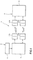
- the system for the transmission of data and energy designated in its entirety by reference number 1 in FIG. 1, comprises a main unit 2 and a secondary unit 3.
- the main unit 2 comprises a power supply unit 4 for supplying a main circuit device 5 which is provided with a first and a second Coupling element L1a, L2a is connected.
- the secondary unit 3 comprises a secondary circuit device 6, which is connected to a third and fourth coupling element L1b, L2b.
- An energy transmission from the main unit 2 to the secondary unit 3 takes place via the first and third coupling elements L1a, L1b.
- a bidirectional data transmission between the main unit 2 and the secondary unit 3 takes place via the second and fourth coupling elements L2a, L2b.
- the coupling elements L1a, L1b, L2a, L2b have the form of coils for generating an inductive coupling.
- the secondary unit 3 comprises a rectifier circuit 7, which converts the alternating supply signal received by the third coupling element L1b into a DC supply voltage V cc .
- the third coupling element L1b is also followed by a first signal shaping circuit 8, which converts the received, essentially sinusoidal signal into an essentially rectangular clock signal, which is supplied on the one hand to a reference counter 9 and on the other hand to a sequence control circuit 10.
- the fourth coupling element L2b is followed by a first transmit / receive changeover switch 11, the switching state of which is determined by the sequence control circuit 10.
- the first transmission / reception switch 11 connects the fourth coupling element L2b to a second signal shaping circuit 12, which is connected on the input side to a data counter 13.
- a microprocessor 14 is connected both to the reference counter 9 and to the data counter 13 and is also connected to the sequence control circuit 10 for mutual data exchange.
- the microprocessor 14 has a reset logic circuit 15, which resets the microprocessor, for example, when the supply voltage V cc is initially applied and in the event of undesired program states occurring.
- a frequency shift keying circuit 16 for the retransmission of data from the secondary unit 3 to the main unit 2 is controlled by the microprocessor 14 for binary frequency shift keying depending on the logical value of the bit to be retransmitted and is connected on the output side to the first transmission / reception switch 11, the frequency shift keying circuit 16 connects in its transmit position with the fourth coupling element L2b.
- the main unit 2 comprises a host computer 17 which is in communication with a second microprocessor 18.
- the main unit 2 further comprises an oscillator 19 which is connected to a power amplifier 20 which is connected on the output side to the first coupling element L1a for transmitting a high-frequency supply change signal to the secondary unit 3.
- the output signal of the oscillator 19 is supplied to the second coupling element L2a as a function of a gate time or switch-on time defined by the second microprocessor 18 in the transmission position of a second transmission / reception switch 21.
- a short or long gate time corresponds to the connection of the output signal of the oscillator 19 to the second coupling element L2a to the transmission of a first or second binary data value from the main unit 2 to the secondary unit 3.
- this connects the second coupling element L2a to a first phase-locked loop 22 and a second phase-locked loop 23, each on the output side are connected to the second microprocessor 18.
- the first phase-locked loop 22 is responsive to signals of the first frequency generated by the frequency shift keying circuit 16 of the slave unit 3, while the second phase-locked loop 22 is responsive to signals of the second frequency from the frequency shift keying circuit 16.
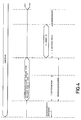
- the transmission method is explained in more detail below with reference to FIGS. 2 to 4.
- a clock signal is generated in the auxiliary unit 3 by the first signal shaping circuit 8, with which the reference counter 9 is clocked or incremented.
- the data counter 13 is counted up in accordance with the vibrations of the transmitted data signal, the sequence control circuit 10 having the reference counter 9 counted from the receipt of the data signal and thus from the start of the counting of the data counter 13.
- the reference counter 9 is used to define a time window with a time base defined by the clock signal.
- the microprocessor 14 effects a readout of the data counter 13 at this point in time.
- the first microprocessor 14 switches the first transmission / reception switch 11 in order to initiate a retransmission of data from the secondary unit 3 to the main unit 2.
- the frequency shift keying circuit 16 now generates a transmission signal with one of two transmission frequencies.
- the second microprocessor 18 of the main unit has switched the second transmission / reception switch 21 after completion of the data transmission to the secondary unit 3, so that either the first or the second phase-locked control circuit 22, 23 to that of the secondary unit 3 sent signal responds, which in turn is detected by the second microprocessor 18. This completes the data retransmission.
- a multi-bit data retransmission requires a corresponding multiple frequency shift keying with a suitable multiple phase-locked loop instead of a binary frequency shift keying.
- the method and system according to the invention enable a very low amount of circuitry on the side of the auxiliary unit 3, which, in addition to comparators and basic gates, can be implemented almost exclusively with flip-flops for realizing counters and dividers. This makes it easy to design the slave unit as a user-specific integrated circuit.
- both the main unit and the secondary unit can have the other unit wait before each data transmission in order to perform certain time-critical tasks.
- the method according to the invention is also characterized by a high level of transmission security.
- a suitable choice of the time window almost any transmission security can be achieved. If the time window defined in terms of circuitry is chosen large enough, the data counter contents can be interpreted by suitable software in such a way that bits are transmitted in pairs, for example, or that the data counter contents corresponds directly to one byte. Of course, this leads to a reduction in the transmission security that can be achieved.
- the data transmission from the slave unit to the main unit is also insensitive to interference due to the selected frequency shift keying modulation method.
- the slave unit can send back one bit after each bit received, the transmission of a byte in both data directions is possible almost simultaneously.
Abstract
Description
Die vorliegende Erfindung betrifft ein Verfahren zum Übertragen von Energie von einer Haupteinheit zu einer Nebeneinheit und zum bidirektionalen Übertragen von Daten zwischen der Haupteinheit und der Nebeneinheit und ein System, bestehend aus einer Haupteinheit und einer Nebeneinheit, zum Übertragen von Energie von der Haupteinheit zu der Nebeneinheit und zum bidirektionalen Übertragen von Daten zwischen der Haupteinheit und der Nebeneinheit.The present invention relates to a method for transmitting energy from a main unit to a sub unit and for bidirectional transmission of data between the main unit and the sub unit, and a system consisting of a main unit and a sub unit for transmitting energy from the main unit to the sub unit and for bidirectional transmission of data between the main unit and the slave unit.
Die GB-A-2182794 offenbart ein Energie- und Daten-Übertragungsverfahren der oben genannten Art. Von der Haupteinheit wird zur Nebeneinheit ein Taktsignal übertragen, das in Figur 10 in der ersten Zeile gezeigt ist. Ein Übertragungszyklus umfaßt jeweils 18 Taktbits, die jeweils ein in einer ersten Richtung übertragbares Datenwort von 8 Bit, ein in der Rückwärtsrichtung übertragbares Datenwort von 8 Bit sowie Umschaltdatenbits umfassen. Mit jedem Takt wird die übertragene Signalfrequenz, die in der zweiten Zeile der Figur 10 dargestellt ist, auf das Vorliegen einer "1" bzw. einer "0" abgetastet, wobei das auf diese Weise erfaßte, sequentiell empfangene Datenwort mit 8 Datenbits nach vollständigem Empfang des Datenwortes einem Komparator zugeführt wird, der dieses Datenwort mit einem vorab in einem Speicher abgelegten Datenwort vergleicht. Bei Übereinstimmung der beiden Datenworte wird ausgangsseitig eine logische "1" erzeugt. Wenn bei einem derartigen Übertragungsverfahren bzw. Übertragungssystem aufgrund einer beliebigen Störung auch nur ein einziges Bit des Datenwortes fehlerhaft erfaßt wird, wird das übertragene Datenwort nicht mehr erkannt.GB-A-2182794 discloses an energy and data transmission method of the above-mentioned type. A clock signal, which is shown in the first line in FIG. 10, is transmitted from the main unit to the secondary unit. Each transmission cycle comprises 18 clock bits, each of which comprises an 8-bit data word that can be transmitted in a first direction, an 8-bit data word that can be transmitted in the reverse direction, and switchover data bits. With each clock, the transmitted signal frequency, which is shown in the second line of FIG. 10, is sampled for the presence of a "1" or a "0", the data word thus acquired, sequentially received, having 8 data bits after complete reception of the data word is fed to a comparator which compares this data word with a data word previously stored in a memory. If the two data words match, a logic "1" is generated on the output side. If even a single bit of the data word is detected incorrectly in such a transmission method or transmission system due to any interference, the transmitted data word is no longer recognized.
Aus der EP-A-288 791 sind bereits ein Verfahren und ein System zum Übertragen von Energie von einer Haupteinheit zu einer Nebeneinheit und zum bidirektionalen Datenübertragen zwischen diesen Einheiten bekannt. Bei dem bekannten Verfahren findet abwechselnd eine Energieübertragung von der Haupteinheit zur Nebeneinheit bzw. eine Datenübertragung von einer Einheit zu der anderen Einheit statt. Die Übertragung von Energie und Daten findet in einem festen Zyklus statt. Jeder Zyklus beginnt mit einem Energieimpuls von vorbestimmter Dauer, der von der Haupteinheit zu der Nebeneinheit übertragen wird, um eine Energieversorgung der Nebenheinheit sicherzustellen. Nach Ablauf einer Abklingphase nach dem Abschalten des Energieimpulses folgt eine Umschaltphase, während der die Hauptelektronik durch Aussenden eines weiteren Energieimpulses die Datenrichtung zwischen der Haupteinheit und der Nebeneinheit für alle weiteren Datenzyklen umschalten kann. Erfolgt während dieser Umschaltphase keine Energieübertragung von der Haupteinheit zu der Nebeneinheit, so wird nach Verstreichen der genannten zweiten Abklingphase eine Datenübertragung in der zuvor festgelegten Datenübertragungsrichtung vorgenommen.EP-A-288 791 already discloses a method and a system for transmitting energy from a main unit to a secondary unit and for bidirectional data transmission known between these units. In the known method, energy transfer takes place alternately from the main unit to the secondary unit or data transfer from one unit to the other unit. The transmission of energy and data takes place in a fixed cycle. Each cycle begins with an energy pulse of a predetermined duration which is transmitted from the main unit to the secondary unit in order to ensure that the secondary unit is supplied with energy. After a decay phase has elapsed after the energy pulse has been switched off, there is a switchover phase during which the main electronics can switch the data direction between the main unit and the secondary unit for all further data cycles by sending out another energy pulse. If there is no energy transmission from the main unit to the secondary unit during this switchover phase, data transmission in the previously defined data transmission direction is carried out after the aforementioned second decay phase has elapsed.
Die Übertragung von Daten zwischen der Haupteinheit und der Nebeneinheit findet in beiden Datenübertragungsrichtungen durch binäre Amplitudenumtastmodulation statt. Dies ermöglicht eine einfache Demodulation und eine hohe Störsicherheit. Bei diesem bekannten Verfahren und System ist es erforderlich, daß die Nebeneinheit ein eigenes frequenzbestimmendes Element aufweist, so daß sie nicht vollständig als anwenderspezifisch integrierte Schaltung implementiert werden kann. Ferner ist es erforderlich, daß die Nebeneinheit über einen Energiespeicher mit relativ hoher Kapazität verfügt, was gleichfalls einer Integration und einer kompakten Bauweise entgegensteht.The transmission of data between the main unit and the slave unit takes place in both data transmission directions by means of binary amplitude shift keying modulation. This enables simple demodulation and high interference immunity. In this known method and system, it is necessary for the secondary unit to have its own frequency-determining element, so that it cannot be completely implemented as a user-specific integrated circuit. Furthermore, it is necessary for the secondary unit to have an energy store with a relatively high capacity, which likewise prevents integration and a compact design.
Aus der EP-A1-02 87 175 ist ein weiteres Verfahren und System zur Übertragung von Energie von einer Haupteinheit zu einer Nebenheinheit und zur bidirektionalen Datenübertragung zwischen diesen Einheiten bekannt. Bei diesem System findet eine gleichzeitige Übertragung von Energie und Daten statt. Bei der Datenübertragung von der Haupteinheit zur Teileinheit wird ein Träger amplitudenmoduliert, wobei, wie später erläutert wird, für jedes zu übertragende Datenbit acht Bits (ein Byte) auf einen hochfrequenten Träger moduliert werden. In der Nebeneinheit wird mittels eines Spannungsteilers aus dem empfangenen, modulierten Signal ein Taktsignal und ein Datensignal gewonnen, um eine übertragene "0" mit einer ersten kleinen Amplitude von einer übertragenen "1" mit einer zweiten, großen Amplitude unterscheiden zu können. Daher ist es erforderlich, eine Anpassung der Sendeleistung der Haupteinheit an die Dämpfung der jeweiligen Übertragungsstrecke vorzunehmen.EP-A1-02 87 175 discloses a further method and system for transmitting energy from a main unit to a secondary unit and for bidirectional data transmission between these units. With this system there is a simultaneous transmission of energy and data. When transferring data from the main unit to the subunit a carrier is amplitude modulated, and, as will be explained later, eight bits (one byte) are modulated onto a high-frequency carrier for each data bit to be transmitted. In the secondary unit, a clock signal and a data signal are obtained from the received, modulated signal by means of a voltage divider in order to be able to distinguish a transmitted "0" with a first small amplitude from a transmitted "1" with a second, large amplitude. It is therefore necessary to adapt the transmission power of the main unit to the attenuation of the respective transmission link.
Die Übertragung von Daten von der Nebeneinheit zur Haupteinheit erfolgt dadurch, daß seitens der Nebeneinheit eine Laständerung an der Sekundärspule mit der halben Trägerfrequenz vorgenommen wird. Die Phasenlage des Schaltens der Laständerung an der Sekundärspule bestimmt den Zustand des rückübertragenen Bits. Um eine synchrone Ablaufsteuerung in der Haupteinheit und in der Nebeneinheit zu erzielen, werden für die Übertragung eines jeden Datenbits von der Haupteinheit zwei Startbits, ein Datenbit mit seinem Komplementärwert, ein Taktbit mit seinem Komplementärwert und zwei Stoppbits übertragen. Nach der Übertragung dieser Bits wird der Träger für eine Zeitdauer von acht Schwingungen des Trägers nicht moduliert. Während dieser Zeit findet die Datenrückübertragung durch Rücksenden eines Datenbits mit der oben beschriebenen Laständerung der Sekundärspule statt.The transmission of data from the subunit to the main unit takes place in that the subunit makes a load change on the secondary coil with half the carrier frequency. The phase position of the switching of the load change on the secondary coil determines the state of the retransmitted bit. In order to achieve synchronous sequence control in the main unit and in the secondary unit, two start bits, one data bit with its complementary value, one clock bit with its complementary value and two stop bits are transmitted from the main unit for the transmission of each data bit. After these bits have been transmitted, the carrier is not modulated for a period of eight oscillations of the carrier. During this time, the data retransmission takes place by sending back a data bit with the load change of the secondary coil described above.
Aus der EP-A2-03 20 015 ist ein weiteres Verfahren und System zum Übertragen von Energie von einer Haupteinheit zu einer Nebeneinheit und zum bidirektionalen Datenübertragen zwischen diesen Einheiten bekannt. Die Datenübertragung von der Haupteinheit zur Nebeneinheit erfolgt durch Pulsdauermodulation eines hochfrequenten Versorgungsspannungssignales mittels dreier verschiedener Puls-Pausen-Verhältnisse,die einer übertragenen "1", einer übertragenen "0" bzw. dem Abrufen eines Bits von der Nebeneinheit entsprechen. Das Rückübertragen von Daten von der Nebeneinheit zur Haupteinheit erfolgt durch Kurzschließen der Sekundärspule in der Abklingphase nach dem übertragenen Puls von der Haupteinheit zur Nebeneinheit, wodurch sich der Abklingpegel der Primärspulenspannung ändert. Ein Vergleicher in der Haupteinheit entscheidet zu einem festgelegten Zeitpunkt innerhalb des Übertragungszyklus, ob der Wert der Primärspulenspannung der Rücksendung einer "1" oder "0" von der Nebeneinheit zur Haupteinheit entspricht.Another method and system for transmitting energy from a main unit to a secondary unit and for bidirectional data transmission between these units is known from EP-A2-03 20 015. The data transmission from the main unit to the secondary unit takes place by pulse duration modulation of a high-frequency supply voltage signal by means of three different pulse-pause ratios, which correspond to a transmitted "1", a transmitted "0" or the retrieval of a bit from the secondary unit. The retransmission of data from the slave unit to the main unit takes place by short-circuiting the secondary coil in the decay phase after the transmitted pulse from the main unit to the secondary unit, as a result of which the decay level of the primary coil voltage changes. A comparator in the main unit decides at a fixed point in time in the transmission cycle whether the value of the primary coil voltage of the return corresponds to a "1" or "0" from the secondary unit to the main unit.
Aus der EP-A2-01 85 610 ist wiederum ein weiteres Verfahren und System zum Übertragen von Energie von einer Haupteinheit zu einer Nebeneinheit und zum bidirektionalen Datenübertragen zwischen diesen Einheiten bekannt. Die Datenübertragung von der Haupteinheit zur Nebeneinheit erfolgt durch Modulation der gegenseitigen Phasenlage zweier kohärenter Versorgungsspannungsschwingungen. Die Datenübertragung in der entgegengesetzten Richtung erfolgt durch Laständerungen an den Spulen der Nebeneinheit. Damit ist eine gleichzeitige bidirektionale Datenübertragung möglich. Für die Übertragung der beiden kohärenten Signale bedarf es zweier räumlich getrennter Spulenpaare.Another method and system for transmitting energy from a main unit to a secondary unit and for bidirectional data transmission between these units is known from EP-A2-01 85 610. The data transmission from the main unit to the secondary unit takes place by modulating the mutual phase position of two coherent supply voltage oscillations. The data transmission in the opposite direction takes place through load changes on the coils of the secondary unit. This enables simultaneous bidirectional data transmission. Two spatially separated pairs of coils are required for the transmission of the two coherent signals.
Aus der US-C-47 30 188 ist ein anderes Verfahren und System zum Übertragen von Energie von einer Haupteinheit zu einer Nebeneinheit und zum unidirektionalen Übertragen von Daten von der Nebeneinheit zur Haupteinheit bekannt. Die Haupteinheit sendet ständig ein hochfrequentes Versorgungswechselsignal aus. Die von der Nebeneinheit zur Haupteinheit zu sendenden Daten werden durch Frequenzumtastung mit Manchester-Codierung moduliert. Zwar bedarf es bei diesem System keines eigenen Oszillators und keines eigenen Energiespeichers in der Nebeneinheit, so daß diese in einfacher Weise als integrierte Schaltung ausgeführt werden kann, jedoch ist dieses System auf eine unidirektionale Datenübertragung beschränkt.Another method and system for transmitting energy from a main unit to a secondary unit and for unidirectionally transmitting data from the secondary unit to the main unit is known from US-C-47 30 188. The main unit continuously sends out a high-frequency change of supply signal. The data to be sent from the slave unit to the main unit are modulated by frequency shift keying with Manchester coding. Although this system does not require its own oscillator and its own energy store in the secondary unit, so that it can be easily implemented as an integrated circuit, this system is limited to unidirectional data transmission.
Aus der DE-A1-36 31 477 ist bereits ein Netzwerk für die Daten- und Energieübertragung bekannt, welches ein Netzwerk aufweist, an das eine Mehrzahl von gleichstrukturierten Einheiten angeschlossen ist. Das Netzwerk wird von einem zentralen Speisegerät mit Energie versorgt. Das Speisegerät dient allein der Energieversorgung mit Wechselspannung. Die Datenübertragung zwischen den einzelnen Einheiten erfolgt dadurch, daß jeweils eine Einheit auf das Netzwerk zugreift, um das dort anliegende Wechselspannungssignal mit einer Amplitudenmodulation zu beaufschlagen.From DE-A1-36 31 477 a network for data and energy transmission is already known, which is a network has, to which a plurality of identically structured units is connected. The network is powered by a central power supply. The power supply unit is used solely for the energy supply with AC voltage. The data transmission between the individual units takes place in that in each case one unit accesses the network in order to apply amplitude modulation to the AC voltage signal present there.
Aus der EP-A2-01 95 626 ist bereits ein Nachrichtenübertragungssystem bekannt, bei dem im Frequenzumtastverfahren modulierte Nachrichten von einer Nebeneinheit zu einer Haupteinheit übertragen werden.A message transmission system is already known from EP-A2-01 95 626, in which messages modulated in the frequency shift keying method are transmitted from a secondary unit to a main unit.
Aus der Fachzeitschrift "Technisches Messen", 1989, Heft 4, Seiten 164 bis 170 ist es bekannt, zum Zwecke der Energieübertragung von einer Haupteinheit zu dezentralen Sensoren Lichtwellenleiter einzusetzen.From the technical journal "Technisches Messen", 1989, volume 4, pages 164 to 170, it is known to use optical fibers for the purpose of transmitting energy from a main unit to decentralized sensors.
Ausgehend von dem oben beschriebenen Stand der Technik liegt der vorliegenden Erfindung die Aufgabe zugrunde, ein Verfahren und System zum Übertragen von Energie von einer Haupteinheit zu einer Nebeneinheit und zum bidirektionalen Übertragen von Daten zwischen diesen Einheiten so weiterzubilden, daß die Nebeneinheit einfach und kompakt aufgebaut ist und daß eine sichere Übertragung der Daten in beide Datenübertragungsrichtungen gewährleistet ist.Based on the prior art described above, the present invention seeks to develop a method and system for transmitting energy from a main unit to a slave unit and for bidirectional transmission of data between these units so that the slave unit is simple and compact and that a secure transmission of the data is guaranteed in both data transmission directions.
Diese Aufgabe wird durch Verfahren mit den in den Patentansprüchen 1 oder 2 angegebenen Verfahrensschritten und durch Systeme mit den in den Patentansprüchen 6 oder 7 angegebenen Merkmalen gelöst.This object is achieved by methods having the method steps specified in
Bevorzugte Weiterbildungen des erfindungsgemäßen Verfahrens sind in den Ansprüchen 3 bis 5 und des erfindungsgemäßen Systemes in den Ansprüchen 8 bis 11 angegeben.Preferred developments of the method according to the invention are specified in
Ein bevorzugtes Ausführungsbeispiel des erfindungsgemäßen Übertragungssystemes, das nach dem erfindungsgemäßen Übertragungsverfahren arbeitet, wird nachfolgend unter Bezugnahme auf die beiliegenden Zeichnungen näher erläutert.A preferred embodiment of the invention Transmission system that works according to the transmission method according to the invention is explained in more detail below with reference to the accompanying drawings.
Es zeigen:
- Fig. 1
- ein Übersichtsdiagramm des Übertragungssystemes;
- Fig. 2
- ein Blockdiagramm eines Ausführungsbeispieles der Nebeneinheit;
- Fig. 3
- ein Blockdiagramm eines Ausführungsbeispieles der Haupteinheit; und
- Fig. 4
- ein zeitliches Ablaufdiagramm zur Erläuterung des erfindungsgemäßen Übertragungsverfahrens.
- Fig. 1
- an overview diagram of the transmission system;
- Fig. 2
- a block diagram of an embodiment of the slave unit;
- Fig. 3
- a block diagram of an embodiment of the main unit; and
- Fig. 4
- a timing diagram to explain the transmission method according to the invention.
Das in Fig. 1 in seiner Gesamtheit mit dem Bezugszeichen 1 bezeichnete System zum Übertragen von Daten und Energie umfaßt eine Haupteinheit 2 und eine Nebeneinheit 3. Die Haupteinheit 2 umfaßt eine Stromversorgungseinheit 4 für die Versorgung einer Hauptschaltungseinrichtung 5, die mit einem ersten und einem zweiten Koppelelement L1a, L2a verbunden ist. Die Nebeneinheit 3 umfaßt eine Nebenschaltungseinrichtung 6, die mit einem dritten und vierten Koppelelement L1b, L2b verbunden ist.The system for the transmission of data and energy, designated in its entirety by
Eine Energieübertragung von der Haupteinheit 2 zu der Nebeneinheit 3 findet über das erste und dritte Koppelelement L1a, L1b statt. Eine bidirektionale Datenübertragung zwischen der Haupteinheit 2 und der Nebeneinheit 3 erfolgt über das zweite und vierte Koppelelement L2a, L2b.An energy transmission from the
Für den Fachmann ist es offensichtlich, daß sowohl für die Datenübertragung wie auch für die Energieübertragung jegliche Art von berührungsfreien Koppelelementen für die induktive oder kapazitive oder optische Kopplung geeignet sind.It is obvious to a person skilled in the art that any type of non-contact coupling elements for inductive or capacitive or optical coupling are suitable for data transmission as well as for energy transmission.
Bei dem bevorzugten, gezeigten Ausführungsbeispiel haben die Koppelelemente L1a, L1b, L2a, L2b die Form von Spulen für die Erzeugung einer induktiven Kopplung.In the preferred exemplary embodiment shown, the coupling elements L1a, L1b, L2a, L2b have the form of coils for generating an inductive coupling.
Wie in Fig. 2 gezeigt ist, umfaßt die Nebeneinheit 3 eine Gleichrichterschaltung 7, die das von dem dritten Koppelelement L1b empfangene Versorgungswechselsignal in eine Versorgungsgleichspannung Vcc umwandelt. Dem dritten Koppelelement L1b ist ferner eine erste Signalformerschaltung 8 nachgeschaltet, die das empfangene, im wesentlichen sinusförmige Signal in ein im wesentlichen rechteckförmiges Taktsignal umwandelt, welches einerseits einem Referenzzähler 9 und andererseits einer Ablaufsteuerschaltung 10 zugeführt wird.As shown in FIG. 2, the
Dem vierten Koppelelement L2b ist ein erster Sende-/Empfangs-Umschalter 11 nachgeschaltet, dessen Schaltzustand von der Ablaufsteuerschaltung 10 bestimmt wird. In seiner Empfangsstellung verbindet der erste Sende-/Empfangs-Umschalter 11 das vierte Koppelelement L2b mit einer zweiten Signalformerschaltung 12, die eingangsseitig mit einem Datenzähler 13 verbunden ist. Ein Mikroprozessor 14 steht ausgangsseitig sowohl mit dem Referenzzähler 9 wie auch mit dem Datenzähler 13 in Verbindung und ist ferner mit der Ablaufsteuerschaltung 10 zum gegenseitigen Datenaustausch verbunden.The fourth coupling element L2b is followed by a first transmit / receive
In an sich üblicher Weise hat der Mikroprozessor 14 eine Rücksetzlogikschaltung 15, die den Mikroprozessor beispielsweise bei einem anfänglichen Anlegen der Versorgungsspannung Vcc sowie im Falle des Auftretens von unerwünschten Programmzuständen rücksetzt.In a conventional manner, the
Eine Frequenzumtastschaltung 16 für die Rückübertragung von Daten von der Nebeneinheit 3 zu der Haupteinheit 2 wird von dem Mikroprozessor 14 für eine binäre Frequenzumtastung je nach dem logischen Wert des rückzuübertragenden Bits angesteuert und steht ausgangsseitig mit dem ersten Sende-/Empfangs-Umschalter 11 in Verbindung, der die Frequenzumtastschaltung 16 in seiner Sendestellung mit dem vierten Koppelelement L2b verbindet.A frequency
Wie in Fig. 3 gezeigt ist, umfaßt die Haupteinheit 2 einen Hostcomputer 17, der mit einem zweiten Mikroprozessor 18 in Datenübertragungsverbindung steht.As shown in Fig. 3, the
Ferner umfaßt die Haupteinheit 2 einen Oszillator 19, der mit einem Leistungsverstärker 20 verbunden ist, welcher ausgangsseitig mit dem ersten Koppelelement L1a zum Übertragen eines hochfrequenten Versorgungswechselsignales zu der Nebeneinheit 3 verbunden ist.The
Das Ausgangssignal des Oszillators 19 wird in Abhängigkeit von einer von dem zweiten Mikroprozessor 18 festgelegten Torzeit oder Einschaltzeit in der Sendestellung eines zweiten Sende-/Empfangs-Umschalters 21 dem zweiten Koppelelement L2a zugeführt. Wie später noch im einzelnen erläutert wird, entspricht eine kurze bzw. lange Torzeit der Durchschaltung des Ausgangssignales des Oszillators 19 zu dem zweiten Koppelelement L2a der Übertragung eines ersten oder zweiten binären Datenwertes von der Haupteinheit 2 zu der Nebeneinheit 3.The output signal of the
Anstelle der unterschiedlich langen Beaufschlagung des zweiten Koppelelementes mit einem Ausgangssignal eines Oszillators von vorbestimmter Frequenz ist es in Abweichung von dem gezeigten Ausführungsbeispiel möglich, einen ersten bzw. einen zweiten Oszillator mit einer ersten bzw. zweiten Frequenz während einer jeweils gleichen Torzeit zur Übertragung des ersten oder zweiten Binärwertes mit dem zweiten Koppelelement L2a zu verbinden.Instead of applying the output of an oscillator of a predetermined frequency to the second coupling element for different lengths, it is possible, in deviation from the exemplary embodiment shown, to have a first or a second oscillator with a first or second frequency during an identical gate time for transmitting the first or to connect the second binary value to the second coupling element L2a.
In der durch den zweiten Mikroprozessor 18 festgelegten Empfangsstellung des zweiten Sende-/Empfangs-Umschalters 21 verbindet dieser das zweite Koppelelement L2a mit einer ersten phasenstarren Regelschleife 22 und einer zweiten phasenstarren Regelschleife 23, die jeweils ausgangsseitig mit dem zweiten Mikroprozessor 18 verbunden sind. Die erste phasenstarre Regelschleife 22 spricht auf Signale der ersten Frequenz an, die die Frequenzumtastschaltung 16 der Nebeneinheit 3 erzeugt, während die zweite phasenstarre Regelschleife 23 auf Signale der zweiten Frequenz von der Frequenzumtastschaltung 16 anspricht.In the receiving position of the second transmission /
Nachfolgend wird unter Bezugnahme auf die Fig. 2 bis 4 das Übertragungsverfahren näher erläutert. Es findet beginnend ab einem Einschalten der Haupteinheit eine kontinuierliche Energieübertragung in Form des hochfrequenten Versorgungswechselsignales von der Haupteinheit 2 zu der Nebeneinheit 3 statt. In der Nebeneinheit 3 wird durch die erste Signalformerschaltung 8 ein Taktsignal generiert, mit dem der Referenzzähler 9 getaktet bzw. inkrementiert wird. Nach dem Empfangen eines Datensignales von der Haupteinheit durch die Nebeneinheit wird der Datenzähler 13 entsprechend den Schwingungen des übertragenen Datensignales hochgezählt, wobei ab dem Empfang des Datensignales und somit ab dem Beginn des Zählens des Datenzählers 13 die Ablaufsteuerschaltung 10 den Referenzzähler 9 zählen läßt. Der Referenzzähler 9 dient zur Definition eines Zeitfensters mit einer von dem Taktsignal festgelegten Zeitbasis.The transmission method is explained in more detail below with reference to FIGS. 2 to 4. Starting when the main unit is switched on, there is continuous energy transmission in the form of the high-frequency supply change signal from the
Sobald der Zählwert des Referenzzählers 9 einen dem Ende des Zeitfensters entsprechenden Maximalwert oder Zählendwert erreicht hat, bewirkt der Mikroprozessor 14 ein Auslesen des Datenzählers 13 zu diesem Zeitpunkt. Zum Ablauf des Zeitfensters schaltet der erste Mikroprozessor 14 den ersten Sende-/Empfangs-Umschalter 11 um, um eine Rückübertragung von Daten von der Nebeneinheit 3 zu der Haupteinheit 2 einzuleiten. Entsprechend des zu übertragenden Datenwertes erzeugt die Frequenzumtastschaltung 16 nun ein Sendesignal mit einer von zwei Sendefrequenzen. Der zweite Mikroprozessor 18 der Haupteinheit hat nach Beendigung der Datenübertragung zu der Nebeneinheit 3 den zweiten Sende-/Empfangs-Umschalter 21 umgeschaltet, so daß entweder die erste oder die zweite phasenstarre Regelschaltung 22, 23 auf das von der Nebeneinheit 3 ausgesandte Signal anspricht, was wiederum von dem zweiten Mikroprozessor 18 erfaßt wird. Hiermit ist die Datenrückübertragung abgeschlossen.As soon as the count value of the
Bei dem erfindungsgemäßen Verfahren können selbstverständlich pro Übertragung in die jeweilige Datenrichtung mehr als nur ein Bit übertragen werden, soweit der Datenzähler 13 eine ausreichende Kapazität hat und die Übertragungsstrecke ausreichend sicher ist. Für eine Mehr-Bit-Datenrückübertragung bedarf es anstelle einer binären Frequenzumtastung einer entsprechenden mehrfachen Frequenzumtastung mit geeigneter mehrfacher phasenstarrer Regelschleife.In the method according to the invention, more than just one bit can of course be transmitted per transmission in the respective data direction, provided the data counter 13 has sufficient capacity and the transmission path is sufficiently secure. A multi-bit data retransmission requires a corresponding multiple frequency shift keying with a suitable multiple phase-locked loop instead of a binary frequency shift keying.
Das erfindungsgemäße Verfahren und System ermöglichen einen sehr niedrigen Schaltungsaufwand auf der Seite der Nebeneinheit 3, die neben Komparatoren und Grundgattern fast ausschließlich mit Flipflops zum Realisieren von Zählern und Teilern implementiert werden kann. Dadurch ist es leicht möglich, die Nebeneinheit als anwenderspezifische integrierte Schaltung auszuführen.The method and system according to the invention enable a very low amount of circuitry on the side of the
Bei dem erfindungsgemäßen Übertragungsverfahren findet eine Zwangssynchronisation statt. Hierbei bestimmt die Haupteinheit den Startzeitpunkt eines Zyklus und die Nebenheit das Ende desselben. Aufgrund dieser Charakteristika des Übertragungsverfahrens können sowohl die Haupteinheit als auch die Nebeneinheit vor einer jeweiligen Datenübertragung die jeweils andere Einheit warten lassen, um bestimmte zeitkritische Aufgaben zu erledigen.In the transmission method according to the invention, forced synchronization takes place. The main unit determines the start time of a cycle and the secondary unit the end of the same. Because of these characteristics of the transmission method, both the main unit and the secondary unit can have the other unit wait before each data transmission in order to perform certain time-critical tasks.
Das erfindungsgemäße Verfahren zeichnet sich ferner durch eine hohe Übertragungssicherheit aus. Durch geeignete Wahl des Zeitfensters kann eine nahezu beliebig große Übertragungssicherheit erreicht werden. Falls das schaltungsmäßig festgelegte Zeitfenster groß genug gewählt ist, kann durch eine geeignete Software eine Interpretation des Datenzählerinhaltes in der Weise erfolgen, daß beispielsweise Bits paarweise übertragen werden oder daß der Datenzählerinhalt direkt einem Byte entspricht. Selbstverständlich führt dies jedoch zu einer Reduktion der erzielbaren Übertragungssicherheit.The method according to the invention is also characterized by a high level of transmission security. With a suitable choice of the time window, almost any transmission security can be achieved. If the time window defined in terms of circuitry is chosen large enough, the data counter contents can be interpreted by suitable software in such a way that bits are transmitted in pairs, for example, or that the data counter contents corresponds directly to one byte. Of course, this leads to a reduction in the transmission security that can be achieved.
Auch die Datenübertragung von der Nebeneinheit zur Haupteinheit ist aufgrund des gewählten Frequenzumtastmodulationsverfahrens störungsunempfindlich.The data transmission from the slave unit to the main unit is also insensitive to interference due to the selected frequency shift keying modulation method.
Dadurch, daß die Nebeneinheit nach jedem empfangenen Bit ein Bit zurücksenden kann, ist die Übertragung eines Bytes in beiden Datenrichtungen fast gleichzeitig möglich.Because the slave unit can send back one bit after each bit received, the transmission of a byte in both data directions is possible almost simultaneously.
Claims (11)
- A process for transmitting energy from a main unit to an auxiliary unit and for transmitting data bidirectionally between said main unit and said auxiliary unit,
comprising the following process steps:- transmitting energy as an alternating supply signal of predetermined frequency from the main unit (2) to the auxiliary unit (3);- generating a clock signal for the auxiliary unit on the basis of the alternating supply signal transmitted from the main unit (2) to the auxiliary unit (3);- transmitting a first data signal from the main unit (2) to the auxiliary unit (3); and- retransmitting a second data signal from the auxiliary unit (3) to the main unit (2);characterized by the following process steps:- counting the number of oscillations of the clock signal from the moment at which the reception of the first data signal begins;- counting the number of oscillations of the first data signal;- stopping the operation of counting the oscillations of the first data signal as soon as a predetermined count, which corresponds to a time window, has been reached in the operation of counting the oscillations of the clock signal; and- determining the received first data value on the basis of the count;- the retransmission of a second data signal from the auxiliary unit (3) to the main unit (2) being effected as soon as the predetermined count, which corresponds to the time window, has been reached in the counting operation of the clock signal. - A process for transmitting energy from a main unit to an auxiliary unit and for transmitting data bidirectionally between said main unit and said auxiliary unit,
comprising the following process steps:- transmitting energy as an alternating supply signal of predetermined frequency from the main unit (2) to the auxiliary unit (3);- generating a clock signal for the auxiliary unit on the basis of the alternating supply signal transmitted from the main unit (2) to the auxiliary unit (3);- transmitting a first data signal from the main unit (2) to the auxiliary unit (3); and- retransmitting a second data signal from the auxiliary unit (3) to the main unit (2);characterized by the following process steps:- counting the number of oscillations of the clock signal from the moment at which the reception of the first data signal begins;- counting the number of oscillations of the first data signal;- stopping the operation of counting the oscillations of the first data signal as soon as a predetermined count, which corresponds to a time window, has been reached in the operation of counting the oscillations of the clock signal; and- determining the received first data value on the basis of the count;- the retransmission of a second data signal from the auxiliary unit (3) to the main unit (2) being effected as soon as the transmission of the first data signal from said main unit (2) to said auxiliary unit (3) has been finished. - A process according to claim 1 or 2, characterized in
- that the auxiliary unit (3) modulates the second data signal by frequency shift keying by means of at least two frequencies. - A process according to one of the claims 1 to 3, characterized in
- that the main unit modulates the first data signal by producing a signal of fixed frequency with an oscillation period depending on the data. - A process according to one of the claims 1 to 3, characterized in
- that the main unit (2) modulates the first data signal by frequency shift keying. - A system comprising a main unit (2) and an auxiliary unit (3) and used for transmitting energy from said main unit (2) to said auxiliary unit (3) and for transmitting data bidirectionally between said main unit (2) and said auxiliary unit (3),- said main unit (2) having the following features:-- an oscillator (19) for producing an alternating supply signal of predetermined frequency;-- a first transmitting means (18, 19, 21) for transmitting a first data signal from the main unit (2) to the auxiliary unit (3); and-- a first receiving means (22, 23, 18) for receiving a second data signal from the auxiliary unit (3); and- said auxiliary unit (3) having the following features:-- a clock signal generating means (8) for generating a clock signal on the basis of the alternating supply signal transmitted from the main unit (2) to the auxiliary unit (3); and-- a second transmitting means (14, 16) for transmitting a second data signal from said auxiliary unit (3) to said main unit (2);characterized in that the auxiliary unit (3) additionally has the following features:-- a reference counter (9) for generating a time window, said reference counter (9) being activated upon reception of the first data signal and counting pulses of the clock signal and generating a time window signal until a count corresponding to the time window has been reached; and-- a data counter (13) counting the oscillations of the first data signal while the time window signal is present;-- said second transmitting means (14, 16) for transmitting a second data signal from the auxiliary unit (3) to the main unit (2) responding to the end of the time window for transmitting the second data signal from the auxiliary unit (3) to the main unit (2).
- A system comprising a main unit (2) and an auxiliary unit (3) and used for transmitting energy from said main unit (2) to said auxiliary unit (3) and for transmitting data bidirectionally between said main unit (2) and said auxiliary unit (3),- said main unit (2) having the following features:-- an oscillator (19) for producing an alternating supply signal of predetermined frequency;-- a first transmitting means (18, 19, 21) for transmitting a first data signal from the main unit (2) to the auxiliary unit (3); and-- a first receiving means (22, 23, 18) for receiving a second data signal from the auxiliary unit (3); and- said auxiliary unit (3) having the following features:-- a clock signal generating means (8) for generating a clock signal on the basis of the alternating supply signal transmitted from the main unit (2) to the auxiliary unit (3); and-- a second transmitting means (14, 16) for transmitting a second data signal from the auxiliary unit (3) to the main unit (2);characterized in that the auxiliary unit (3) additionally has the following features:-- a reference counter (9) for generating a time window, said reference counter (9) being activated upon reception of the first data signal and counting pulses of the clock signal and generating a time window signal until a count corresponding to the time window has been reached; and-- a data counter (13) counting the oscillations of the first data signal while the time window signal is present;-- said second transmitting means (14, 16) for transmitting a second data signal from the auxiliary unit (3) to the main unit (2) responding to the end of the transmission of the first data signal from said main unit (2) to said auxiliary unit (3) for transmitting the second data signal from said auxiliary unit (3) to said main unit (2).
- A system according to claim 6 or 7, characterized in
- that the main unit (2) as well as the auxiliary unit (3) each include an energy and data transmitting element (L1a, L1b; L2a, L2b) for the transmission of energy from the main unit (2) to the auxiliary unit (3) and for the bidirectional transmission of data between these units. - A system according to claim 8, characterized in
- that the auxiliary unit (3) additionally has the following features:-- a first digital control device (10, 14, 15);-- a first transmitting and receiving switch (11) connected to said first digital control device (10, 14, 15) and to the data transmitting element (L2b) of the auxiliary unit (3);-- a first signal-shaping circuit (12), which is connected downstream of said first transmitting and receiving switch (11) and the output side of which is connected to the data counter (13), said data counter (13) being, in turn, connected to the first digital control device (10, 14, 15) on the output side thereof;-- a rectifier circuit (7) connected to the energy transmitting element (L1b); and-- a second signal-shaping circuit (8), which is also connected to the energy transmitting element (L1b) and the output side of which is connected to the reference counter (9), said reference counter (9) being, in turn, connected to the first digital control device (10, 14, 15) on its output side. - A system according to claim 9, characterized in
- that the second transmitting means is provided with a frequency shift keying circuit (16), which is connected to the digital control device (10, 14, 15) on its input side and to the first transmitting and receiving switch (11) on its output side. - A system according to one of the claims 6 to 10, characterized in
- that the main unit (2) additionally has the following features:-- a second digital control device (17, 18);-- a second transmitting and receiving switch (21) connected to said second digital control device (17, 18) and to the data transmitting element (L2a) of the main unit (2);--- said second transmitting and receiving switch (21) connecting, in its transmitting position, the oscillator (19) to the data transmitting element (L2a) of the main unit (2) during a gating time predetermined by the second digital control device (17, 18) in accordance with the data to be transmitted, and--- connecting, in its receiving position, the data transmitting element (L2a) of the main unit (2) to first and second phase-locked loops (22, 23), which are connected to said second digital control device (17, 18) on their output sides.
Priority Applications (1)
| Application Number | Priority Date | Filing Date | Title |
|---|---|---|---|
| AT91910294T ATE99474T1 (en) | 1990-06-12 | 1991-06-05 | METHOD AND SYSTEM FOR TRANSMITTING POWER AND DATA. |
Applications Claiming Priority (2)
| Application Number | Priority Date | Filing Date | Title |
|---|---|---|---|
| DE4018814 | 1990-06-12 | ||
| DE4018814A DE4018814A1 (en) | 1990-06-12 | 1990-06-12 | METHOD AND SYSTEM FOR TRANSMITTING ENERGY AND DATA |
Publications (2)
| Publication Number | Publication Date |
|---|---|
| EP0533709A1 EP0533709A1 (en) | 1993-03-31 |
| EP0533709B1 true EP0533709B1 (en) | 1993-12-29 |
Family
ID=6408272
Family Applications (1)
| Application Number | Title | Priority Date | Filing Date |
|---|---|---|---|
| EP19910910294 Expired - Lifetime EP0533709B1 (en) | 1990-06-12 | 1991-06-05 | Process and system for transmitting energy and data |
Country Status (7)
| Country | Link |
|---|---|
| EP (1) | EP0533709B1 (en) |
| JP (1) | JPH05502147A (en) |
| KR (1) | KR960000146B1 (en) |
| AU (1) | AU640026B2 (en) |
| CA (1) | CA2084995A1 (en) |
| DE (2) | DE4018814A1 (en) |
| WO (1) | WO1991020135A1 (en) |
Cited By (1)
| Publication number | Priority date | Publication date | Assignee | Title |
|---|---|---|---|---|
| US7458453B2 (en) | 2003-06-27 | 2008-12-02 | Christian Bauer Gmbh + Co. | Disk clutch and method for operating same |
Families Citing this family (6)
| Publication number | Priority date | Publication date | Assignee | Title |
|---|---|---|---|---|
| DE19636031A1 (en) * | 1996-09-05 | 1998-03-12 | Varchmin J Uwe Prof Dr Ing | Communication system for explosive detonation |
| US8363744B2 (en) | 2001-06-10 | 2013-01-29 | Aloft Media, Llc | Method and system for robust, secure, and high-efficiency voice and packet transmission over ad-hoc, mesh, and MIMO communication networks |
| DE10228060A1 (en) * | 2002-06-19 | 2004-01-15 | Robert Bosch Gmbh | Method and circuit arrangement for the transmission of binary user data |
| DE10240671A1 (en) | 2002-09-04 | 2004-03-18 | Christian Bauer Gmbh + Co | Combustion engine knocking sensor has a piezo-resistive amorphous carbon, or DLC, layer as a sensor element, which provides an electrical signal that is evaluated to detect knocking |
| AT512504B1 (en) * | 2012-03-22 | 2013-09-15 | Seibersdorf Labor Gmbh | Apparatus and method for determining the capacity |
| CN110350943B (en) * | 2018-09-28 | 2023-09-15 | 深圳市速腾聚创科技有限公司 | Wireless communication device with energy transmission and wireless communication method with energy transmission |
Family Cites Families (14)
| Publication number | Priority date | Publication date | Assignee | Title |
|---|---|---|---|---|
| FR2290801A1 (en) * | 1974-11-08 | 1976-06-04 | Thomson Csf | Numeric transmission and reception centre - which is for use at millimetric wavelengths, has automatic frame length correction system |
| JPS5732144A (en) * | 1980-08-06 | 1982-02-20 | Nippon Gakki Seizo Kk | Energy and/or data transmitter and receiver |
| AU1999983A (en) * | 1982-10-01 | 1984-04-05 | Sugar Research Limited | Load monitoring means |
| DE3336717A1 (en) * | 1983-10-08 | 1985-04-25 | Dai Nippon Printing Co., Ltd., Tokio/Tokyo | METHOD AND DEVICE FOR CONTACTLESS, ELECTROMAGNETIC TRANSFERRING OF CONTROL COMMANDS AND DATA |
| JPS60171475A (en) * | 1984-02-15 | 1985-09-04 | アイデンティフィケ−ション・デバイセス・インコ−ポレ−テッド | Discriminating system |
| JPS61101885A (en) * | 1984-10-24 | 1986-05-20 | Tdk Corp | Ic card connecting system |
| DE3447560A1 (en) * | 1984-12-21 | 1986-07-10 | Angewandte Digital Elektronik Gmbh, 2051 Brunstorf | DEVICE FOR CONTACTLESS SIGNAL AND ENERGY TRANSMISSION |
| GB8507281D0 (en) * | 1985-03-20 | 1985-04-24 | Emi Ltd | Data communications system |
| JPS61283981A (en) * | 1985-06-11 | 1986-12-13 | Nippon Denzai Kogyo Kenkyusho:Kk | Integrated circuit card |
| DE3631477C3 (en) * | 1986-09-16 | 1995-01-26 | Siegfried Dipl Ing Schwarz | Network for control, measurement and regulation technology for data and energy transmission |
| NL8700861A (en) * | 1987-04-13 | 1988-11-01 | Nedap Nv | READING, WRITING SYSTEM WITH MINIATURE INFORMATION CARRIER. |
| DE3714195A1 (en) * | 1987-04-29 | 1988-11-10 | Fraunhofer Ges Forschung | METHOD FOR CONTACTLESS ENERGY AND DATA TRANSFER, AND MECHANICAL AND ELECTRONICALLY CODED LOCK |
| JPH0732368B2 (en) * | 1987-12-09 | 1995-04-10 | オムロン株式会社 | Data communication device |
| ATE108965T1 (en) * | 1987-12-09 | 1994-08-15 | Omron Tateisi Electronics Co | INDUCTIVE DATA TRANSMISSION SYSTEM. |
-
1990
- 1990-06-12 DE DE4018814A patent/DE4018814A1/en active Granted
-
1991
- 1991-06-05 CA CA002084995A patent/CA2084995A1/en not_active Abandoned
- 1991-06-05 WO PCT/DE1991/000480 patent/WO1991020135A1/en active IP Right Grant
- 1991-06-05 JP JP3509507A patent/JPH05502147A/en active Pending
- 1991-06-05 AU AU79719/91A patent/AU640026B2/en not_active Ceased
- 1991-06-05 KR KR1019920703164A patent/KR960000146B1/en active IP Right Grant
- 1991-06-05 EP EP19910910294 patent/EP0533709B1/en not_active Expired - Lifetime
- 1991-06-05 DE DE91910294T patent/DE59100782D1/en not_active Expired - Fee Related
Cited By (1)
| Publication number | Priority date | Publication date | Assignee | Title |
|---|---|---|---|---|
| US7458453B2 (en) | 2003-06-27 | 2008-12-02 | Christian Bauer Gmbh + Co. | Disk clutch and method for operating same |
Also Published As
| Publication number | Publication date |
|---|---|
| DE4018814C2 (en) | 1993-02-04 |
| AU640026B2 (en) | 1993-08-12 |
| JPH05502147A (en) | 1993-04-15 |
| KR960000146B1 (en) | 1996-01-03 |
| DE59100782D1 (en) | 1994-02-10 |
| CA2084995A1 (en) | 1991-12-13 |
| WO1991020135A1 (en) | 1991-12-26 |
| DE4018814A1 (en) | 1992-01-02 |
| EP0533709A1 (en) | 1993-03-31 |
| AU7971991A (en) | 1992-01-07 |
| KR930701798A (en) | 1993-06-12 |
Similar Documents
| Publication | Publication Date | Title |
|---|---|---|
| DE3041134C2 (en) | Data transmission arrangement for data transmission via a power line | |
| EP0191019B1 (en) | Unit for transferring binary data between a movable data medium and a fixed station | |
| DE2403098A1 (en) | SYSTEM FOR TRANSMITTING COLUMN-PHASE MANCHESTER-CODED TWO-VALUE DATA SIGNALS | |
| DE3237405C2 (en) | Data transmission system | |
| DE3041945A1 (en) | TRANSMITTER RECEIVER FOR DATA TRANSMITTED BY OPTICAL FIBERS | |
| DD269478A5 (en) | ELECTRONIC DATA PROCESSING SYSTEM | |
| EP0533709B1 (en) | Process and system for transmitting energy and data | |
| DE2449660C3 (en) | Method and device for the synchronization of time-division multiplex autonomous transmitter stations with equal rights | |
| EP0150540B1 (en) | Method for data communication as well as a station for carrying out the method | |
| EP0559159B1 (en) | Electronic device for locking | |
| DE1462455A1 (en) | Circuit arrangement for a digital data transmission system | |
| DE2134783C3 (en) | Method for determining errors in the intermediate points provided with regenerators of a transmission system operating with pulse code modulation | |
| EP0715412B1 (en) | Process and arrangement for the investigation of phase variations of a reference input signal of a phase locked loop | |
| DE1960790C3 (en) | Address-coded transmission system based on the pulse position modulation method | |
| EP0079527B1 (en) | Data transmission installation for full duplex transmission | |
| DE2439246C3 (en) | Phase synchronization circuit | |
| DE2818916C2 (en) | Device for synchronizing several transmitting stations transmitting autonomously in time division multiplex mode | |
| DE2912854A1 (en) | Demodulator for binary frequency modulated signals - uses difference between measured and expected periods to determine state change at receiver, after given constant time | |
| EP0433706B1 (en) | Auxiliary signal transmission in a communication system for high bit-rate digital signals | |
| DE2513780C3 (en) | Phase synchronization circuit for regulating the synchronization between the transmitting and receiving drums in facsimile machines | |
| DE2260344A1 (en) | TRANSMITTERS FOR THE GENERATION OF FREQUENCY CONTROLLING SIGNALS AND THESE SENDING DATA MODEM | |
| DE2106172B2 (en) | DIGITAL SYNCHRONOUS MODEM | |
| EP0332054B1 (en) | Method for transmitting a digital signal and status information | |
| DE69727034T2 (en) | transponder system | |
| DE2715939C2 (en) | Method for generating a clock multiple |
Legal Events
| Date | Code | Title | Description |
|---|---|---|---|
| PUAI | Public reference made under article 153(3) epc to a published international application that has entered the european phase |
Free format text: ORIGINAL CODE: 0009012 |
|
| 17P | Request for examination filed |
Effective date: 19921113 |
|
| AK | Designated contracting states |
Kind code of ref document: A1 Designated state(s): AT BE CH DE DK ES FR GB GR IT LI LU NL SE |
|
| 17Q | First examination report despatched |
Effective date: 19930517 |
|
| GRAA | (expected) grant |
Free format text: ORIGINAL CODE: 0009210 |
|
| AK | Designated contracting states |
Kind code of ref document: B1 Designated state(s): AT BE CH DE DK ES FR GB GR IT LI LU NL SE |
|
| PG25 | Lapsed in a contracting state [announced via postgrant information from national office to epo] |
Ref country code: GR Free format text: LAPSE BECAUSE OF FAILURE TO SUBMIT A TRANSLATION OF THE DESCRIPTION OR TO PAY THE FEE WITHIN THE PRESCRIBED TIME-LIMIT Effective date: 19931229 Ref country code: SE Effective date: 19931229 Ref country code: NL Effective date: 19931229 Ref country code: ES Free format text: THE PATENT HAS BEEN ANNULLED BY A DECISION OF A NATIONAL AUTHORITY Effective date: 19931229 Ref country code: DK Effective date: 19931229 Ref country code: BE Effective date: 19931229 |
|
| REF | Corresponds to: |
Ref document number: 99474 Country of ref document: AT Date of ref document: 19940115 Kind code of ref document: T |
|
| ITF | It: translation for a ep patent filed |
Owner name: JACOBACCI CASETTA & PERANI S.P.A. |
|
| GBT | Gb: translation of ep patent filed (gb section 77(6)(a)/1977) |
Effective date: 19940111 |
|
| RIN2 | Information on inventor provided after grant (corrected) |
Free format text: KUEHN, JUERGEN * DALSASS, KARL-GUENTHER * SCHERER, KLAUS * VOLKWEIN, BERND |
|
| REF | Corresponds to: |
Ref document number: 59100782 Country of ref document: DE Date of ref document: 19940210 |
|
| ET | Fr: translation filed | ||
| PGFP | Annual fee paid to national office [announced via postgrant information from national office to epo] |
Ref country code: AT Payment date: 19940613 Year of fee payment: 4 |
|
| NLV1 | Nl: lapsed or annulled due to failure to fulfill the requirements of art. 29p and 29m of the patents act | ||
| PG25 | Lapsed in a contracting state [announced via postgrant information from national office to epo] |
Ref country code: LU Free format text: LAPSE BECAUSE OF NON-PAYMENT OF DUE FEES Effective date: 19940630 |
|
| PLBE | No opposition filed within time limit |
Free format text: ORIGINAL CODE: 0009261 |
|
| STAA | Information on the status of an ep patent application or granted ep patent |
Free format text: STATUS: NO OPPOSITION FILED WITHIN TIME LIMIT |
|
| 26N | No opposition filed | ||
| PG25 | Lapsed in a contracting state [announced via postgrant information from national office to epo] |
Ref country code: AT Effective date: 19950605 |
|
| PGFP | Annual fee paid to national office [announced via postgrant information from national office to epo] |
Ref country code: FR Payment date: 19960614 Year of fee payment: 6 |
|
| PGFP | Annual fee paid to national office [announced via postgrant information from national office to epo] |
Ref country code: CH Payment date: 19960621 Year of fee payment: 6 |
|
| PGFP | Annual fee paid to national office [announced via postgrant information from national office to epo] |
Ref country code: DE Payment date: 19960703 Year of fee payment: 6 |
|
| PGFP | Annual fee paid to national office [announced via postgrant information from national office to epo] |
Ref country code: GB Payment date: 19970527 Year of fee payment: 7 |
|
| PG25 | Lapsed in a contracting state [announced via postgrant information from national office to epo] |
Ref country code: LI Free format text: LAPSE BECAUSE OF NON-PAYMENT OF DUE FEES Effective date: 19970630 Ref country code: CH Free format text: LAPSE BECAUSE OF NON-PAYMENT OF DUE FEES Effective date: 19970630 |
|
| REG | Reference to a national code |
Ref country code: CH Ref legal event code: PL |
|
| PG25 | Lapsed in a contracting state [announced via postgrant information from national office to epo] |
Ref country code: FR Free format text: LAPSE BECAUSE OF NON-PAYMENT OF DUE FEES Effective date: 19980227 |
|
| PG25 | Lapsed in a contracting state [announced via postgrant information from national office to epo] |
Ref country code: DE Free format text: LAPSE BECAUSE OF NON-PAYMENT OF DUE FEES Effective date: 19980303 |
|
| REG | Reference to a national code |
Ref country code: FR Ref legal event code: ST |
|
| REG | Reference to a national code |
Ref country code: FR Ref legal event code: ST |
|
| PG25 | Lapsed in a contracting state [announced via postgrant information from national office to epo] |
Ref country code: GB Free format text: LAPSE BECAUSE OF NON-PAYMENT OF DUE FEES Effective date: 19980605 |
|
| GBPC | Gb: european patent ceased through non-payment of renewal fee |
Effective date: 19980605 |
|
| PG25 | Lapsed in a contracting state [announced via postgrant information from national office to epo] |
Ref country code: IT Free format text: LAPSE BECAUSE OF NON-PAYMENT OF DUE FEES;WARNING: LAPSES OF ITALIAN PATENTS WITH EFFECTIVE DATE BEFORE 2007 MAY HAVE OCCURRED AT ANY TIME BEFORE 2007. THE CORRECT EFFECTIVE DATE MAY BE DIFFERENT FROM THE ONE RECORDED. Effective date: 20050605 |