EP0529343B1 - Méthode d'établir une liaison de communication entre un terminal de communication, connectée à un central de communication, et plusieurs terminaux - Google Patents
Méthode d'établir une liaison de communication entre un terminal de communication, connectée à un central de communication, et plusieurs terminaux Download PDFInfo
- Publication number
- EP0529343B1 EP0529343B1 EP92113109A EP92113109A EP0529343B1 EP 0529343 B1 EP0529343 B1 EP 0529343B1 EP 92113109 A EP92113109 A EP 92113109A EP 92113109 A EP92113109 A EP 92113109A EP 0529343 B1 EP0529343 B1 EP 0529343B1
- Authority
- EP
- European Patent Office
- Prior art keywords
- devices
- group
- information
- connection
- communication
- Prior art date
- Legal status (The legal status is an assumption and is not a legal conclusion. Google has not performed a legal analysis and makes no representation as to the accuracy of the status listed.)
- Expired - Lifetime
Links
Images
Classifications
-
- H—ELECTRICITY
- H04—ELECTRIC COMMUNICATION TECHNIQUE
- H04Q—SELECTING
- H04Q11/00—Selecting arrangements for multiplex systems
- H04Q11/04—Selecting arrangements for multiplex systems for time-division multiplexing
- H04Q11/0407—Selecting arrangements for multiplex systems for time-division multiplexing using a stored programme control
-
- H—ELECTRICITY
- H04—ELECTRIC COMMUNICATION TECHNIQUE
- H04M—TELEPHONIC COMMUNICATION
- H04M11/00—Telephonic communication systems specially adapted for combination with other electrical systems
- H04M11/02—Telephonic communication systems specially adapted for combination with other electrical systems with bell or annunciator systems
Definitions
- the invention relates to a method for establishing a connection between a source communication device with a plurality of devices in the form of separate loudspeakers and / or communication terminals having loudspeakers, each of which is connected to the program-controlled communication system, for the purpose of being used by an operator of origin.
- Communication device simultaneously for this plurality of devices each for the announcement determined via the activated speaker, the communication system u. a. has device-related units for signaling-specific connection of the devices, a coupling network for switching through the connection paths and a programmable digital computer system used for central control of the communication system, with at least one system memory for storing program modules and data, and wherein the digital signaling information via a signaling channel and the voice information can be transmitted via a voice channel via the connecting line.
- the modern digital computer-controlled communication switching systems allow the use of different communication terminals. These can therefore differ in their type of connection and, if necessary, in the dialing procedure on which they are based.
- digital subscriber line modules are used to connect digital communication terminals.
- Analog communication terminals are connected via "analog connection technology".
- the underlying communication switching system consists in principle of a large number of switching-related functional units and a programmable digital computer system that controls these functional units and all switching-related ones Processes monitored.
- the computing system is informed with information about the operating state of the functional units and about changes in state, in particular about entries on the connected terminal devices. If necessary, it can therefore immediately create and output appropriate control instructions and messages.
- Such communication switching systems are also capable of controlling or realizing additional control processes that go beyond the actual switching process.
- additional functions are generally referred to as performance features, a large number of different performance features being known in particular for the “voice” communication service.
- Such features can be initiated either when the switching device is busy or during an existing call. This can be done, for example, by selecting certain code numbers or code number combinations and / or by pressing so-called function keys.
- Such features include, for example, acoustic information for waiting participants, the display of operator information on an optical display device and the direct response of a selected participant.
- a subscriber has the option of activating the loudspeaker present on the terminal of the desired subscriber next to the handset for the purpose of hands-free calling. It is envisaged that such activation of the existing loudspeaker can also be carried out by a subscriber on a plurality of connected terminals. This subscriber can then simultaneously make an announcement to the other subscribers concerned via the established connections.
- a conceivable solution is that the connection to the devices in question is established one after the other. Starting with the first of the devices provided for such a collective announcement, after sending out command information for the effective connection of the loudspeaker first the arrival of the feedback confirming this connection is switched through the connection and the connection to the next device of the intended device series is established.
- the next connection establishment is initiated in the same way. This then continues successively until the last device predetermined for this announcement process initiated.
- the system-related runtimes add up, so that an undesirably large amount of time is required, in particular in the case of a large number of devices to be addressed, before the intended announcement can be made.
- there are two-digit second values such a waiting time would be perceived as uncomfortable by those who intend to make an announcement.
- such a process is linked to relatively complex performance feature-specific program procedures, which also have consequences for the actual switching procedures.
- the invention has for its object to provide a method in which a simultaneous announcement of a subscriber to a variety of devices is possible with simple control procedures and in which the time period between the activation of the feature "collective announcement" and the actual connection of all of those to be addressed Devices is minimized.
- This object is achieved on the basis of the features mentioned in the preamble in that from the group of devices which are required for an announcement and are stored in the system memory, on the basis of the input made by the operator on the original communication device and at least characterizing the service, a fixed, limited maximum number from devices for which there is no communication relationship can be called, in which the computer system prompts the simultaneous transmission of command information for the activation of the respective loudspeaker via the signaling channel that any preparatory activation of the loudspeaker by one of the called devices identifying and emitting information is reported back to the computer control as acknowledgment information, that the connection establishment procedure is then initiated and the connection to the device in question is established, and that, based on each receipt information received, the command information is transmitted to the next free device in the group in the specified sequence is initiated, and that this is always initiated until this maximum number of devices to be called is reached again, that these calls are continuously continued in this way, and that, based on the receipt information for the last device in the group, the operator is informed about the activation of all Devices
- the number of devices that are in the "call" state is selected so that a dynamic overload is reliably avoided with regard to the other processes taking place in the system. It makes sense to choose a number that requires a total time to establish the connection that approximately corresponds to that in which acknowledgment information is received by a first of these simultaneously addressed devices. This has the advantage over a serial treatment that the time required to activate all devices to be addressed is reduced by the ratio of this maximum number of devices of the "start group".
- the devices assigned to each group according to certain criteria are individually assigned Input can be selectively called up by the operator.
- the existing devices can thus be combined into such groups according to the most varied of criteria.
- a subgroup can therefore be classified in one or more groups.
- the selected assignments are possible in any mix and can be changed easily.
- a counter checks that the maximum number of devices called up is not exceeded.
- This counter which can be implemented in a simple manner by a software solution, is reset by a count value with each initiated acknowledgment character and increased by a count value with each transmitted command information, the counter position corresponding to the predetermined maximum number of the respective devices addressed not being exceeded.
- the counter With the initialization of the "collective announcement" feature, the counter is brought into the position corresponding to the number of the start group and the transmission of the command information is controlled in such a way that this value which determines the number of simultaneous calls is retained until the last device in the group is called.
- group-specific input from the different groups is the devices of each group in the above-mentioned Callable way.
- the subscriber who then registers as a addressed subscriber by entering a certain code information can then immediately initiate a call with the waiting subscriber. In this specially marked state, it is switched through to this connection by the central controller.
- a further development of the method provides that the activation of a loudspeaker in a terminal as well as the activation of all free devices of the group called up is indicated by an optical or an acoustic attention sign.
- the individual subscribers are therefore informed in advance of a subsequent announcement and the operator who intends to make this announcement is informed that this announcement can be started.
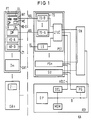
- a central component of the digital communication system KA shown schematically in FIG. 1 is a switching network SN, via which communication terminals - indicated schematically by KE-D and KE-A - can be connected to one another or to lines VL leading to a public switching system or to other private branch exchanges.
- the central switching network SN is under the control of a central system control ASt, which represents the top hierarchical level of the communication system. This structure level is formed by a central control processor DP, which coordinates the interaction of all modules and modules of the communication system KA.
- the system control is also equipped with an upstream access control DCL and a memory MEM.
- the unit DCL serves as an interface to the periphery, which, as the 'master' of an HDLC connection, carries out protocol handling on a signaling channel.
- the switching database and all switching-relevant programs and the associated data are stored in the memory MEM.
- Essential functions of the central control processor DP are therefore the storage and processing of switching technology programs in accordance with requirements and the control and monitoring of the local bus LB, to which the units DCL and the switching network SN are connected, facing the periphery. Additional common functions of the central data processor DP are, for example, operational processing and safety-related displays.
- peripheral interfaces PS1 ... PSn which have subscriber-related set modules TS and line-related set modules LS.
- An interface control LTUC is assigned to these peripheral interfaces PS1 ... PSn. This controls the establishment of the connection between the communication terminals KE ..., for which purpose a connection establishment method implemented in terms of programming is provided.
- the processes or program modules that handle the signaling protocols with the communication terminals KE are predominantly implemented in the interfaces PS.
- the connection establishment methods or program modules used to check the authorization with regard to services, features, etc., and to control the connection via the digital central switching network SN, are implemented in the central system controller ASt.
- the periphery is supplemented by a module SU, which is used to supply the communication switching system KA with signaling information and with music recordings made while connections are on hold.
- This module SU also contains signaling-supporting devices and also test devices.
- This additional module is connected in a manner similar to the interfaces PS via a PCM-structured connection and via a transmission link used for transferring and receiving control information. This information is used e.g. B. in the standardized transmission method HDLC.
- conventional terminal devices KE-A with analog transmission can each be connected to the communication system KA via a connecting line ASL. This is done for each peripheral interface PS for the digital communication terminals KE-D via a set module TS-D that controls the corresponding digital information transmission and for the analog communication terminals through a correspondingly adapted set module TS-A. These are available several times for each interface and serve u. a. to convert the different signaling information from the individual end devices and - based on the set module LS - from other networks to a format used uniformly within the communication system. A plurality of line connections are accessible on each set assembly TS.
- a digital communication terminal which for example only represents a voice terminal, is usually equipped with a display DL, a dialing keyboard WT and a set of function keys FT.
- a microphone MI and a loudspeaker LR are arranged in the terminal.
- a loudspeaker LR which is used, for example, as a room loudspeaker, can also be connected via a connecting line ASL to a set module TS-A which is responsible for such analog connections, instead of such a device.
- a so-called collective announcement from an operating or switching station or from any subscriber terminal.
- an operator or an internal telephone subscriber initiates the effective connection of the loudspeakers LR present in predefined telephone telephones as well as of existing separate loudspeakers LRs.
- the devices to be addressed in the form of telephone devices or separate loudspeakers are combined in different groups GR1 ... GRn.
- the devices which by definition belong to a group are themselves arranged in individual sub-groups Z1 ... Zm. Each of these sub-groups comprises a maximum number of devices, for example 20 devices.
- a device can e.g. B. represent a digital telephone device KE-D or a separate speaker LRs.
- Each subgroup can be assigned to one or more main groups GR ...
- the individual subgroups and main groups can be selected according to points of view that are meaningful for the system operator.
- the division into subgroups, which then in turn make up a main group means that the options for addressing participants in connection with a collective announcement can be made very variable. This announcement can be initiated by the operator for each main group by entering a code number KZ individually assigned to this group.
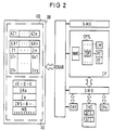
- the customer-specific assignments of the individual devices KE-D and KE-A connected to the communication system KA to the respective group are stored according to FIG. 2 in a permanent memory area KD of the database DB containing the customer data. All programs relevant to switching technology are also stored in this database. It can be contained, for example, in the memory MEM in FIG. 1.
- Another memory area in the database DB can be, for example, a working memory AS of the computer system ASt be the communication system in which the dynamic data arising in connection with a collective announcement are stored.
- the control structure of the digital communication system shown in FIG. 2 has a modular character and has two hierarchical levels of program control. One of them is used to control peripheral devices by means of line technology program modules DH1, DH2 ... DHx (device handler), each adapted to a type of communication terminal. These include not only the KE ... communication terminals connected to the periphery, but also central circuit technology devices, such as connection kits and switching matrix. Each of these line technology program modules DH offers a system-uniform interface to the switching technology structure level, which in the present case is represented by a switching procedure program module CP.
- line technology structure level DH so-called line technology program modules DTE for digital end devices and ATE for analog end devices assigned to the individual terminal types are indicated in the program module DH2.
- switching control structure level sub-modules are provided for different sub-tasks of connection control.
- the exchange of information between the line technology structure level and the switching technology structure level takes place by means of defined messages which are transmitted via a software bus structure SWB.
- the switching control program module CP, the line technology program modules DH1, DH2 ... DHy and the software bus SWB have access to the database DB of the entire communication system by means of database access routines DBAR.
- further modules are provided, of which the operating technology program modules are indicated by way of example with AMA. These are used to handle operational tasks.
- the database DB is also accessible to at least some of them via defined database access routines.
- the line technology program modules DH1, DH2 ... DHy are designed specifically for communication terminal types in such a way that they each control the signaling method and the user interface of the corresponding communication terminal type.
- the switching procedure program module CP is structured independently of the type of communication terminal and is independent of the communication service in such a way that it controls the maximum range of functions of the peripheral devices and devices in terms of control technology.
- the tasks of the switching procedure program module CP thus include the subprocesses of the entire switching procedure necessary for controlling the connection establishment and clearing down. So z. B. Authorizations checked and election checks carried out. There is also a signaling of switching technology states between the communication terminals and it is possible to activate and deactivate switching technology performance features from the various switching technology states.
- An essential component of the switching technology structure level CP is the switching procedure program module CPTL (Call Processing Trunk Line), which in turn is divided into different sub-modules.
- the switching control procedures are carried out by a communication system controller DP shown schematically in FIG. 2 within the unit CPTL.
- the LM module and the PC module provided in connection with a collective announcement are shown as representative of the feature program modules provided in the system.
- the performance feature program modules also include a network control program module NWC, with which the entire logical connection memory control and the control of the switching network SN are implemented.
- the basic structure of the permanent and dynamic data associated with a collective announcement process to be processed by the program module PC is indicated in the database DB.
- the sub-area KD there are those permanent data which are queried during a collective announcement initiated by a communication terminal and are at least partially transferred to the working memory area AS of the database DB.
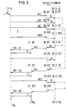
- the permanent memories KD of the database DB also contain the data relevant in connection with a collective announcement to be carried out. It is stored there which identifier KZ is assigned to one of the main groups GR1 ... GRn formed from the subgroups according to certain criteria. Furthermore, those subgroups Z ... that each belong to a main group GR are stored. For example, eight main groups and eight subgroups can be formed. One of the subgroups Z1 ... Zm can be assigned to one or more main groups. For each of the individual subgroups Z1 ... Zm, a list of those devices G ... that each belong to this subgroup Z ... is stored. For example, devices G1r ... G1x should form subgroup Z1.
- a maximum value of "20" can be set for "x".
- the associated devices are then also stored in lists. So include B. to the subgroup Zm the devices Gs1 ... Gsy, where "y" can assume values from one to 20, for example.
- a maximum of 160 devices could therefore be combined in a main group in the selected exemplary embodiment with eight subgroups and a maximum of 20 devices for each of these subgroups.
- each time a connection establishment procedure is initiated by a communication terminal a memory area assigned to this device is queried in the database storing permanent data.
- the calling communication terminal is clearly identified.
- the services and authorizations relating to usable performance features stored therein are read and, if necessary, stored in a memory area of the database which stores dynamic data.
- the physical functions contained therein, such as. B. the terminal interfaces used, read and saved. This data is evaluated or queried in the course of establishing a connection and when initiating switching procedures.
- the sub-module CP-A assigned to the switching control structure level CP in the exemplary embodiment for the first ten devices of the group GR selected by the code number simultaneously sends command information BI for the effective connection of the respective loudspeaker in the digital terminal KE-D or the direct establishment of the connection to the separate loudspeaker LRs KE-A defined as the analog terminal KE-A.
- the number of command information sent at the same time must be selected so that the system is not overloaded. It can e.g. B. ten devices receive a call at the same time.
- the subgroups, to which the currently called devices belong, are also stored in the memory area AS as corresponding information Za.
- a counter PZ also implemented as a software solution, corresponding to the calls VA sent out at the same time as the calls for the exemplary embodiment assumed value "10".
- the ten devices called up by the message VA1 ... VA10 are devices which were identified as being in the "free state” by the corresponding control by the switching control of the system.
- a called device sends a feedback An to the corresponding module of the line technology structure level DH
- the message Ans generated there generates an acknowledgment information ZRS in the switching control structure level.
- the connection establishment procedure is initiated for a digital terminal and the connection is established.
- the receipt information is generated when the connection is established in the line structure level DH.
- the counter PZ is reset by one count value with each receipt information. If, for example, return information arrives first from the device KE-D-B1, the acknowledgment information ZRS ... B1 is formed therefrom.
- the sub-module CP-A which is responsible for the subscriber A intending to make an announcement, causes the transmission of a sound signal TS to the respectively called digital terminal, by which the subscriber in question is informed about the connection of the loudspeaker in the terminal.
- command information BI is transmitted in the manner described to the next free device KE-D-B1 in the zone currently being addressed.
- the counter value is increased by the value "1", so that the number "10" is reached again for the devices called up at the same time.
- the next free device is prompted in the manner described to carry out the effective connection of the loudspeaker.
- an attention sign for example in the form of a specific audible tone Tsg, is transmitted to the originating device KE-DA. This then informs the subscriber concerned that the intended announcement can be made. Via the activated loudspeaker, this announcement affects all devices that are represented by the group GR ... defined with the selected key figure.
- the target address data of those devices are determined with the help of the database access procedures, which are provided for a collective announcement via the group-specific code number KZ.
- the point in time at which the loudspeakers of all the addressed devices KE-D-B1 ... KE-D-Bg were activated can be determined. Due to the permanent data stored in the memory area KD of the database, the group information defined by the selected key figure can be quickly assigned to the respective connections to be set up.
- the subgroups Z ... addressed overall are identified in the working memory AS (FIG. 2) by a corresponding marking bit MB.
Landscapes
- Engineering & Computer Science (AREA)
- Signal Processing (AREA)
- Computer Networks & Wireless Communication (AREA)
- Exchange Systems With Centralized Control (AREA)
- Telephonic Communication Services (AREA)
Claims (6)
- Méthode pour établir une liaison de communication entre un appareil de communication de départ et plusieurs appareils sous la forme de haut-parleurs séparés (LRs) et/ou de terminaux de communication (KE-A-, KE-B) présentant des haut-parleurs, qui sont respectivement branchés à un central de communication (KA) commandé par programme, à des fins de transmettre une annonce d'un opérateur de l'appareil de communication de départ destinée simultanément à cette multitude d'appareils pour émission à chaque fois par les haut-parleurs activés, le central de communication comprenant entre autres des unités relatives aux appareils pour allumer les appareils individuellement selon la nature de la signalisation, un réseau de connexion (SN) pour interconnexion des voies de liaison et un système informatisé numérique programmable (ASt) servant à la commande centrale du central de communication, avec au moins une mémoire système (MEM) destinée à mémoriser des modules de programmes et des données et les informations de signalisation numériques étant transmises par un canal de signalisation et les informations vocales par une voie vocale à travers la ligne d'abonné (ASL) caractérisée en ce que du groupe (GR) des appareils (KE-D) qu'on utilise en cas de besoin pour une annonce et qui sont mémorisés dans la mémoire système (KD), on fait appel en raison d'une entrée caractérisant au moins la facilité et réalisée par l'opérateur sur le terminal de communication de départ, tout d'abord à un nombre maximal limité déterminé d'appareils pour lesquels il n'existe pas de rapport de communication, en déclenchant par le système informatique (ASt) la transmission simultanée dans chaque cas d'une information de commande (BI) pour activer le haut-parleur respectif (LR ou LRs) par le canal de signalisation, en ce que chaque activation préliminairement effectuée du haut-parleur est annoncée en retour à la commande informatisée par une information d'accusé de réception (ZRS) caractérisant l'appareil appelé (KE-D-BI...Bg) et émise par lui, en ce que ensuite la procédure d'établissement de liaison est enclenchée et la liaison établie avec l'appareil en question, et en ce que en raison de chaque information d'accusé de réception reçue, la transmission de l'information de commande (BI) est déclenchée à chaque fois vers le prochain appareil libre du groupe GR selon l'ordre prédéterminé, et en ce que ceci est à chaque fois initié jusqu'à ce que ce nombre maximal d'appareils à appeler, par ex. dix, soit à nouveau atteint, en ce que de cette manière, ces appels se poursuivent en continu et en ce que en raison de l'information d'accusé de réception pour le dernier appareil (KE-D-Bg) du groupe (GR), un signe d'avertissement informant l'opérateur de l'activation effectuée de tous les appareils de ce groupe est transmis à l'appareil de communication de départ (KE-D-A) et est affiché à cet endroit.
- Méthode selon la revendication 1 caractérisée en ce que plusieurs groupes (GR1...GRn) d'appareils sont prévus, constitués à leur tour de sous-groupes (Z1...Zm) qui présentent au maximum un nombre prédéterminé d'appareils et qui sont facultativement rassemblés en différentes combinaisons appropriées dans le groupe respectif et mémorisés selon l'affectation prédéterminée (KD) et en ce que chaque groupe peut être sélectivement appelé pour l'annonce selon le besoin par l'entrée d'un nombre caractéristique KZ qui lui est affecté individuellement.
- Méthode selon la revendication 1 caractérisée en ce que le non dépassement du nombre maximal des appareils respectivement appelés est contrôlé par un compteur (PZ) qui est décalé d'une valeur numérique avec chaque signe d'accusé de réception initié et augmenté d'une valeur numérique avec chaque information de commande transmise resp. avec chaque appel, la position du compteur correspondant à ce nombre maximal, par ex. dix, n'étant pas dépassée.
- Méthode selon les revendications 1 à 3 caractérisée en ce qu'à partir de l'état de commutation particulier, dans lequel une liaison externe arrivant a été transférée en état d'attente par l'abonné appelant cette liaison, par ex. position d'opérateur, les appareils d'un groupe peuvent être appelés de la manière préalablement citée par l'entrée d'un nombre caractéristique individuel caractérisant en outre cet état particulier de sorte que l'abonné qui s'annonce ensuite par l'entrée d'une certaine information codée, est connecté sur l'appel en attente.
- Méthode selon la revendication 1 caractérisée en ce que l'activation effectuée d'un haut-parleur après réception de l'accusé de réception est affichée par un signe d'avertissement optique ou acoustique transmis à l'appareil concerné.
- Méthode selon la revendication 1 caractérisée en ce qu'après activation de tous les appareils libres du groupe respectivement appelé, un signe d'avertissement optique ou acoustique est transmis au terminal de l'opérateur envisageant d'envoyer une annonce collective.
Applications Claiming Priority (2)
| Application Number | Priority Date | Filing Date | Title |
|---|---|---|---|
| DE4128777 | 1991-08-29 | ||
| DE4128777 | 1991-08-29 |
Publications (3)
| Publication Number | Publication Date |
|---|---|
| EP0529343A2 EP0529343A2 (fr) | 1993-03-03 |
| EP0529343A3 EP0529343A3 (en) | 1993-07-28 |
| EP0529343B1 true EP0529343B1 (fr) | 1997-01-29 |
Family
ID=6439455
Family Applications (1)
| Application Number | Title | Priority Date | Filing Date |
|---|---|---|---|
| EP92113109A Expired - Lifetime EP0529343B1 (fr) | 1991-08-29 | 1992-07-31 | Méthode d'établir une liaison de communication entre un terminal de communication, connectée à un central de communication, et plusieurs terminaux |
Country Status (3)
| Country | Link |
|---|---|
| US (1) | US5509059A (fr) |
| EP (1) | EP0529343B1 (fr) |
| DE (1) | DE59207980D1 (fr) |
Families Citing this family (5)
| Publication number | Priority date | Publication date | Assignee | Title |
|---|---|---|---|---|
| DE59711792D1 (de) * | 1996-03-20 | 2004-08-26 | Siemens Schweiz Ag Zuerich | Verfahren zum übertragen von informationen von einer informationsquelle zu informationsempfängern |
| DE19639891A1 (de) * | 1996-09-27 | 1998-04-09 | Siemens Ag | Anordnung zur Verteilung von Informationen an einen Verteilerkreis in einem Fernsprechnetz |
| DE19712533C1 (de) * | 1997-03-25 | 1998-06-25 | Siemens Ag | Kommunikationssystem und Verfahren zur Steuerung der Ausgabe von Rückmeldeinformationen von dem Kommunikationssystem |
| EP1313302A3 (fr) * | 2001-11-16 | 2004-02-25 | Tenovis GmbH & Co. KG | Terminal de communication et procédé d'opération d'un tel terminal |
| US8401166B1 (en) | 2008-05-20 | 2013-03-19 | Peerless Network, Inc. | Systems and methods of mitigating phantom call traffic |
Family Cites Families (7)
| Publication number | Priority date | Publication date | Assignee | Title |
|---|---|---|---|---|
| US4298977A (en) * | 1979-09-10 | 1981-11-03 | Bell Telephone Laboratories, Incorporated | Broadcast and alternate message time slot interchanger |
| JPS61105138A (ja) * | 1984-10-29 | 1986-05-23 | Nec Corp | 無線電話装置 |
| US4802200A (en) * | 1985-08-27 | 1989-01-31 | Nippon Telegraph And Telephone Corporation | Radio telephone system control apparatus and method |
| IE870097L (en) * | 1987-01-16 | 1988-07-16 | Nat & City Patents Ltd | Communication system |
| FR2623677B1 (fr) * | 1987-11-20 | 1993-05-28 | Prescom Sarl | Circuit de mise en conferences d'une pluralite de participants dans des systemes de telecommunications |
| DE3807358A1 (de) * | 1988-03-05 | 1989-09-14 | Telefonbau & Normalzeit Gmbh | Verfahren zum steuern einer gegen- oder wechselsprechanlage |
| US5237602A (en) * | 1990-10-01 | 1993-08-17 | Lazik George L | Remotely-activated telephone system for communication with the disabled |
-
1992
- 1992-07-31 DE DE59207980T patent/DE59207980D1/de not_active Expired - Fee Related
- 1992-07-31 EP EP92113109A patent/EP0529343B1/fr not_active Expired - Lifetime
-
1994
- 1994-11-03 US US08/333,865 patent/US5509059A/en not_active Expired - Fee Related
Also Published As
| Publication number | Publication date |
|---|---|
| DE59207980D1 (de) | 1997-03-13 |
| EP0529343A3 (en) | 1993-07-28 |
| US5509059A (en) | 1996-04-16 |
| EP0529343A2 (fr) | 1993-03-03 |
Similar Documents
| Publication | Publication Date | Title |
|---|---|---|
| EP0306693B1 (fr) | Système de communication numérique à structure modulaire | |
| EP0813330B1 (fr) | Procédé d'établissement de connexion, central de commutation, processeur de service et réseau de communication | |
| EP0295470B1 (fr) | Méthode pour un dispositif de commutation commandé par calculateur, en particulier pour un central téléphonique à touches avec la possibilité de transfert d'appel | |
| EP0529343B1 (fr) | Méthode d'établir une liaison de communication entre un terminal de communication, connectée à un central de communication, et plusieurs terminaux | |
| EP0589248A2 (fr) | Méthode et disposition pour l'affichage de numéros d'appel aux postes téléphoniques d'un central téléphonique privé | |
| EP0535602B1 (fr) | Procédé pour faire fonctionner un système de communication avec commande programmée dans lequel une demande de connexion est signalée simultanément dans plusieurs terminaux de communication | |
| EP0535601B1 (fr) | Procédé pour l'établissement de connexions de conférence dans un système de communication à commande par processeur | |
| EP0557777B1 (fr) | Système de télécommunication commandé par programme avec option de rappel automatique | |
| EP0720399B1 (fr) | Méthode de commande du mode de fonctionnement d'un appareil mobile associé à un système de communication à commande programmée | |
| EP0866594B1 (fr) | Système de communication, en particulier système de communication privé à commande par programme dans lequel une fonction de calendrier est réalisée | |
| DE4020618C2 (de) | Verfahren zur Signalisierung von Fernsprech-Rückrufverbindungen | |
| EP1282293B1 (fr) | Procédé et dispositif pour le traitement d'appels dans un réseau de télécommunication et ses units liées | |
| DE4006048C2 (fr) | ||
| EP0352700B1 (fr) | Méthode pour réaliser une procédure de commande de service spécifique dans un système de communication commandé par calculateur en particulier un système de communication à touches avec la possibilité de branchement sur une connexion existante | |
| DE3818086C2 (fr) | ||
| EP0360898B1 (fr) | Méthode pour prendre des appels qui sont signalés par un central de communication à un ou plusieurs terminaux de communication à lignes multiples | |
| DE10145987A1 (de) | Verfahren zur Auswahl eines Leistungsmerkmals und zugehörige Einheiten | |
| DE4232862C1 (de) | Verfahren für die Auswertung betriebstechnischer Dateninformationen bei einer programmgesteuerten Nebenstellenanlage mit daran angeschlossenen Mobilendgeräten | |
| EP0707404B1 (fr) | Procédé pour la réception des appels dans un système de communication | |
| EP0861007B1 (fr) | Procédé d'acheminement d'appels dans un système de communication | |
| DE3720186C2 (de) | Verfahren für eine rechnergesteuerte Vermittlungseinrichtung, insbesondere für eine sogenannte KEY-Fernsprechvermittlungseinrichtung | |
| DE19948090B4 (de) | Verfahren zum Anschliessen eines Endgerätes an eine Telekommunikationsanlage sowie zugehörige elektronische Baueinheiten | |
| DE10055252B4 (de) | Verfahren zur Übertragung von Informationen oder Daten in einem Telekommunikationssystem | |
| DE4124711A1 (de) | Verfahren zur uebermittlung einer abgespeicherten nachricht an ein rufendes fernsprechendgeraet einer kommunikationsanlage bzw. vermittlungseinrichtung | |
| DE3432144A1 (de) | Verfahren fuer eine mit einem betriebstechnischen terminal ausgeruestete waehlnebenstellenanlage |
Legal Events
| Date | Code | Title | Description |
|---|---|---|---|
| PUAI | Public reference made under article 153(3) epc to a published international application that has entered the european phase |
Free format text: ORIGINAL CODE: 0009012 |
|
| AK | Designated contracting states |
Kind code of ref document: A2 Designated state(s): DE FR GB IT |
|
| PUAL | Search report despatched |
Free format text: ORIGINAL CODE: 0009013 |
|
| AK | Designated contracting states |
Kind code of ref document: A3 Designated state(s): DE FR GB IT |
|
| 17P | Request for examination filed |
Effective date: 19930915 |
|
| GRAG | Despatch of communication of intention to grant |
Free format text: ORIGINAL CODE: EPIDOS AGRA |
|
| 17Q | First examination report despatched |
Effective date: 19960619 |
|
| GRAH | Despatch of communication of intention to grant a patent |
Free format text: ORIGINAL CODE: EPIDOS IGRA |
|
| GRAH | Despatch of communication of intention to grant a patent |
Free format text: ORIGINAL CODE: EPIDOS IGRA |
|
| GRAA | (expected) grant |
Free format text: ORIGINAL CODE: 0009210 |
|
| AK | Designated contracting states |
Kind code of ref document: B1 Designated state(s): DE FR GB IT |
|
| ET | Fr: translation filed | ||
| REF | Corresponds to: |
Ref document number: 59207980 Country of ref document: DE Date of ref document: 19970313 |
|
| ITF | It: translation for a ep patent filed |
Owner name: 0508;07MIFSTUDIO JAUMANN |
|
| GBT | Gb: translation of ep patent filed (gb section 77(6)(a)/1977) |
Effective date: 19970410 |
|
| PLBE | No opposition filed within time limit |
Free format text: ORIGINAL CODE: 0009261 |
|
| STAA | Information on the status of an ep patent application or granted ep patent |
Free format text: STATUS: NO OPPOSITION FILED WITHIN TIME LIMIT |
|
| 26N | No opposition filed | ||
| REG | Reference to a national code |
Ref country code: GB Ref legal event code: IF02 |
|
| PGFP | Annual fee paid to national office [announced via postgrant information from national office to epo] |
Ref country code: GB Payment date: 20040708 Year of fee payment: 13 |
|
| PGFP | Annual fee paid to national office [announced via postgrant information from national office to epo] |
Ref country code: FR Payment date: 20040716 Year of fee payment: 13 |
|
| PGFP | Annual fee paid to national office [announced via postgrant information from national office to epo] |
Ref country code: DE Payment date: 20040920 Year of fee payment: 13 |
|
| PG25 | Lapsed in a contracting state [announced via postgrant information from national office to epo] |
Ref country code: IT Free format text: LAPSE BECAUSE OF NON-PAYMENT OF DUE FEES;WARNING: LAPSES OF ITALIAN PATENTS WITH EFFECTIVE DATE BEFORE 2007 MAY HAVE OCCURRED AT ANY TIME BEFORE 2007. THE CORRECT EFFECTIVE DATE MAY BE DIFFERENT FROM THE ONE RECORDED. Effective date: 20050731 Ref country code: GB Free format text: LAPSE BECAUSE OF NON-PAYMENT OF DUE FEES Effective date: 20050731 |
|
| PG25 | Lapsed in a contracting state [announced via postgrant information from national office to epo] |
Ref country code: DE Free format text: LAPSE BECAUSE OF NON-PAYMENT OF DUE FEES Effective date: 20060201 |
|
| GBPC | Gb: european patent ceased through non-payment of renewal fee |
Effective date: 20050731 |
|
| PG25 | Lapsed in a contracting state [announced via postgrant information from national office to epo] |
Ref country code: FR Free format text: LAPSE BECAUSE OF NON-PAYMENT OF DUE FEES Effective date: 20060331 |
|
| REG | Reference to a national code |
Ref country code: FR Ref legal event code: ST Effective date: 20060331 |