EP0529343B1 - Method for establishing communication between a communication terminal, connected to a communication exchange, and a plurality of further terminals - Google Patents
Method for establishing communication between a communication terminal, connected to a communication exchange, and a plurality of further terminals Download PDFInfo
- Publication number
- EP0529343B1 EP0529343B1 EP92113109A EP92113109A EP0529343B1 EP 0529343 B1 EP0529343 B1 EP 0529343B1 EP 92113109 A EP92113109 A EP 92113109A EP 92113109 A EP92113109 A EP 92113109A EP 0529343 B1 EP0529343 B1 EP 0529343B1
- Authority
- EP
- European Patent Office
- Prior art keywords
- devices
- group
- information
- connection
- communication
- Prior art date
- Legal status (The legal status is an assumption and is not a legal conclusion. Google has not performed a legal analysis and makes no representation as to the accuracy of the status listed.)
- Expired - Lifetime
Links
Images
Classifications
-
- H—ELECTRICITY
- H04—ELECTRIC COMMUNICATION TECHNIQUE
- H04Q—SELECTING
- H04Q11/00—Selecting arrangements for multiplex systems
- H04Q11/04—Selecting arrangements for multiplex systems for time-division multiplexing
- H04Q11/0407—Selecting arrangements for multiplex systems for time-division multiplexing using a stored programme control
-
- H—ELECTRICITY
- H04—ELECTRIC COMMUNICATION TECHNIQUE
- H04M—TELEPHONIC COMMUNICATION
- H04M11/00—Telephonic communication systems specially adapted for combination with other electrical systems
- H04M11/02—Telephonic communication systems specially adapted for combination with other electrical systems with bell or annunciator systems
Definitions
- the invention relates to a method for establishing a connection between a source communication device with a plurality of devices in the form of separate loudspeakers and / or communication terminals having loudspeakers, each of which is connected to the program-controlled communication system, for the purpose of being used by an operator of origin.
- Communication device simultaneously for this plurality of devices each for the announcement determined via the activated speaker, the communication system u. a. has device-related units for signaling-specific connection of the devices, a coupling network for switching through the connection paths and a programmable digital computer system used for central control of the communication system, with at least one system memory for storing program modules and data, and wherein the digital signaling information via a signaling channel and the voice information can be transmitted via a voice channel via the connecting line.
- the modern digital computer-controlled communication switching systems allow the use of different communication terminals. These can therefore differ in their type of connection and, if necessary, in the dialing procedure on which they are based.
- digital subscriber line modules are used to connect digital communication terminals.
- Analog communication terminals are connected via "analog connection technology".
- the underlying communication switching system consists in principle of a large number of switching-related functional units and a programmable digital computer system that controls these functional units and all switching-related ones Processes monitored.
- the computing system is informed with information about the operating state of the functional units and about changes in state, in particular about entries on the connected terminal devices. If necessary, it can therefore immediately create and output appropriate control instructions and messages.
- Such communication switching systems are also capable of controlling or realizing additional control processes that go beyond the actual switching process.
- additional functions are generally referred to as performance features, a large number of different performance features being known in particular for the “voice” communication service.
- Such features can be initiated either when the switching device is busy or during an existing call. This can be done, for example, by selecting certain code numbers or code number combinations and / or by pressing so-called function keys.
- Such features include, for example, acoustic information for waiting participants, the display of operator information on an optical display device and the direct response of a selected participant.
- a subscriber has the option of activating the loudspeaker present on the terminal of the desired subscriber next to the handset for the purpose of hands-free calling. It is envisaged that such activation of the existing loudspeaker can also be carried out by a subscriber on a plurality of connected terminals. This subscriber can then simultaneously make an announcement to the other subscribers concerned via the established connections.
- a conceivable solution is that the connection to the devices in question is established one after the other. Starting with the first of the devices provided for such a collective announcement, after sending out command information for the effective connection of the loudspeaker first the arrival of the feedback confirming this connection is switched through the connection and the connection to the next device of the intended device series is established.
- the next connection establishment is initiated in the same way. This then continues successively until the last device predetermined for this announcement process initiated.
- the system-related runtimes add up, so that an undesirably large amount of time is required, in particular in the case of a large number of devices to be addressed, before the intended announcement can be made.
- there are two-digit second values such a waiting time would be perceived as uncomfortable by those who intend to make an announcement.
- such a process is linked to relatively complex performance feature-specific program procedures, which also have consequences for the actual switching procedures.
- the invention has for its object to provide a method in which a simultaneous announcement of a subscriber to a variety of devices is possible with simple control procedures and in which the time period between the activation of the feature "collective announcement" and the actual connection of all of those to be addressed Devices is minimized.
- This object is achieved on the basis of the features mentioned in the preamble in that from the group of devices which are required for an announcement and are stored in the system memory, on the basis of the input made by the operator on the original communication device and at least characterizing the service, a fixed, limited maximum number from devices for which there is no communication relationship can be called, in which the computer system prompts the simultaneous transmission of command information for the activation of the respective loudspeaker via the signaling channel that any preparatory activation of the loudspeaker by one of the called devices identifying and emitting information is reported back to the computer control as acknowledgment information, that the connection establishment procedure is then initiated and the connection to the device in question is established, and that, based on each receipt information received, the command information is transmitted to the next free device in the group in the specified sequence is initiated, and that this is always initiated until this maximum number of devices to be called is reached again, that these calls are continuously continued in this way, and that, based on the receipt information for the last device in the group, the operator is informed about the activation of all Devices
- the number of devices that are in the "call" state is selected so that a dynamic overload is reliably avoided with regard to the other processes taking place in the system. It makes sense to choose a number that requires a total time to establish the connection that approximately corresponds to that in which acknowledgment information is received by a first of these simultaneously addressed devices. This has the advantage over a serial treatment that the time required to activate all devices to be addressed is reduced by the ratio of this maximum number of devices of the "start group".
- the devices assigned to each group according to certain criteria are individually assigned Input can be selectively called up by the operator.
- the existing devices can thus be combined into such groups according to the most varied of criteria.
- a subgroup can therefore be classified in one or more groups.
- the selected assignments are possible in any mix and can be changed easily.
- a counter checks that the maximum number of devices called up is not exceeded.
- This counter which can be implemented in a simple manner by a software solution, is reset by a count value with each initiated acknowledgment character and increased by a count value with each transmitted command information, the counter position corresponding to the predetermined maximum number of the respective devices addressed not being exceeded.
- the counter With the initialization of the "collective announcement" feature, the counter is brought into the position corresponding to the number of the start group and the transmission of the command information is controlled in such a way that this value which determines the number of simultaneous calls is retained until the last device in the group is called.
- group-specific input from the different groups is the devices of each group in the above-mentioned Callable way.
- the subscriber who then registers as a addressed subscriber by entering a certain code information can then immediately initiate a call with the waiting subscriber. In this specially marked state, it is switched through to this connection by the central controller.
- a further development of the method provides that the activation of a loudspeaker in a terminal as well as the activation of all free devices of the group called up is indicated by an optical or an acoustic attention sign.
- the individual subscribers are therefore informed in advance of a subsequent announcement and the operator who intends to make this announcement is informed that this announcement can be started.
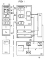
- a central component of the digital communication system KA shown schematically in FIG. 1 is a switching network SN, via which communication terminals - indicated schematically by KE-D and KE-A - can be connected to one another or to lines VL leading to a public switching system or to other private branch exchanges.
- the central switching network SN is under the control of a central system control ASt, which represents the top hierarchical level of the communication system. This structure level is formed by a central control processor DP, which coordinates the interaction of all modules and modules of the communication system KA.
- the system control is also equipped with an upstream access control DCL and a memory MEM.
- the unit DCL serves as an interface to the periphery, which, as the 'master' of an HDLC connection, carries out protocol handling on a signaling channel.
- the switching database and all switching-relevant programs and the associated data are stored in the memory MEM.
- Essential functions of the central control processor DP are therefore the storage and processing of switching technology programs in accordance with requirements and the control and monitoring of the local bus LB, to which the units DCL and the switching network SN are connected, facing the periphery. Additional common functions of the central data processor DP are, for example, operational processing and safety-related displays.
- peripheral interfaces PS1 ... PSn which have subscriber-related set modules TS and line-related set modules LS.
- An interface control LTUC is assigned to these peripheral interfaces PS1 ... PSn. This controls the establishment of the connection between the communication terminals KE ..., for which purpose a connection establishment method implemented in terms of programming is provided.
- the processes or program modules that handle the signaling protocols with the communication terminals KE are predominantly implemented in the interfaces PS.
- the connection establishment methods or program modules used to check the authorization with regard to services, features, etc., and to control the connection via the digital central switching network SN, are implemented in the central system controller ASt.
- the periphery is supplemented by a module SU, which is used to supply the communication switching system KA with signaling information and with music recordings made while connections are on hold.
- This module SU also contains signaling-supporting devices and also test devices.
- This additional module is connected in a manner similar to the interfaces PS via a PCM-structured connection and via a transmission link used for transferring and receiving control information. This information is used e.g. B. in the standardized transmission method HDLC.
- conventional terminal devices KE-A with analog transmission can each be connected to the communication system KA via a connecting line ASL. This is done for each peripheral interface PS for the digital communication terminals KE-D via a set module TS-D that controls the corresponding digital information transmission and for the analog communication terminals through a correspondingly adapted set module TS-A. These are available several times for each interface and serve u. a. to convert the different signaling information from the individual end devices and - based on the set module LS - from other networks to a format used uniformly within the communication system. A plurality of line connections are accessible on each set assembly TS.
- a digital communication terminal which for example only represents a voice terminal, is usually equipped with a display DL, a dialing keyboard WT and a set of function keys FT.
- a microphone MI and a loudspeaker LR are arranged in the terminal.
- a loudspeaker LR which is used, for example, as a room loudspeaker, can also be connected via a connecting line ASL to a set module TS-A which is responsible for such analog connections, instead of such a device.
- a so-called collective announcement from an operating or switching station or from any subscriber terminal.
- an operator or an internal telephone subscriber initiates the effective connection of the loudspeakers LR present in predefined telephone telephones as well as of existing separate loudspeakers LRs.
- the devices to be addressed in the form of telephone devices or separate loudspeakers are combined in different groups GR1 ... GRn.
- the devices which by definition belong to a group are themselves arranged in individual sub-groups Z1 ... Zm. Each of these sub-groups comprises a maximum number of devices, for example 20 devices.
- a device can e.g. B. represent a digital telephone device KE-D or a separate speaker LRs.
- Each subgroup can be assigned to one or more main groups GR ...
- the individual subgroups and main groups can be selected according to points of view that are meaningful for the system operator.
- the division into subgroups, which then in turn make up a main group means that the options for addressing participants in connection with a collective announcement can be made very variable. This announcement can be initiated by the operator for each main group by entering a code number KZ individually assigned to this group.
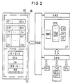
- the customer-specific assignments of the individual devices KE-D and KE-A connected to the communication system KA to the respective group are stored according to FIG. 2 in a permanent memory area KD of the database DB containing the customer data. All programs relevant to switching technology are also stored in this database. It can be contained, for example, in the memory MEM in FIG. 1.
- Another memory area in the database DB can be, for example, a working memory AS of the computer system ASt be the communication system in which the dynamic data arising in connection with a collective announcement are stored.
- the control structure of the digital communication system shown in FIG. 2 has a modular character and has two hierarchical levels of program control. One of them is used to control peripheral devices by means of line technology program modules DH1, DH2 ... DHx (device handler), each adapted to a type of communication terminal. These include not only the KE ... communication terminals connected to the periphery, but also central circuit technology devices, such as connection kits and switching matrix. Each of these line technology program modules DH offers a system-uniform interface to the switching technology structure level, which in the present case is represented by a switching procedure program module CP.
- line technology structure level DH so-called line technology program modules DTE for digital end devices and ATE for analog end devices assigned to the individual terminal types are indicated in the program module DH2.
- switching control structure level sub-modules are provided for different sub-tasks of connection control.
- the exchange of information between the line technology structure level and the switching technology structure level takes place by means of defined messages which are transmitted via a software bus structure SWB.
- the switching control program module CP, the line technology program modules DH1, DH2 ... DHy and the software bus SWB have access to the database DB of the entire communication system by means of database access routines DBAR.
- further modules are provided, of which the operating technology program modules are indicated by way of example with AMA. These are used to handle operational tasks.
- the database DB is also accessible to at least some of them via defined database access routines.
- the line technology program modules DH1, DH2 ... DHy are designed specifically for communication terminal types in such a way that they each control the signaling method and the user interface of the corresponding communication terminal type.
- the switching procedure program module CP is structured independently of the type of communication terminal and is independent of the communication service in such a way that it controls the maximum range of functions of the peripheral devices and devices in terms of control technology.
- the tasks of the switching procedure program module CP thus include the subprocesses of the entire switching procedure necessary for controlling the connection establishment and clearing down. So z. B. Authorizations checked and election checks carried out. There is also a signaling of switching technology states between the communication terminals and it is possible to activate and deactivate switching technology performance features from the various switching technology states.
- An essential component of the switching technology structure level CP is the switching procedure program module CPTL (Call Processing Trunk Line), which in turn is divided into different sub-modules.
- the switching control procedures are carried out by a communication system controller DP shown schematically in FIG. 2 within the unit CPTL.
- the LM module and the PC module provided in connection with a collective announcement are shown as representative of the feature program modules provided in the system.
- the performance feature program modules also include a network control program module NWC, with which the entire logical connection memory control and the control of the switching network SN are implemented.
- the basic structure of the permanent and dynamic data associated with a collective announcement process to be processed by the program module PC is indicated in the database DB.
- the sub-area KD there are those permanent data which are queried during a collective announcement initiated by a communication terminal and are at least partially transferred to the working memory area AS of the database DB.
- the permanent memories KD of the database DB also contain the data relevant in connection with a collective announcement to be carried out. It is stored there which identifier KZ is assigned to one of the main groups GR1 ... GRn formed from the subgroups according to certain criteria. Furthermore, those subgroups Z ... that each belong to a main group GR are stored. For example, eight main groups and eight subgroups can be formed. One of the subgroups Z1 ... Zm can be assigned to one or more main groups. For each of the individual subgroups Z1 ... Zm, a list of those devices G ... that each belong to this subgroup Z ... is stored. For example, devices G1r ... G1x should form subgroup Z1.
- a maximum value of "20" can be set for "x".
- the associated devices are then also stored in lists. So include B. to the subgroup Zm the devices Gs1 ... Gsy, where "y" can assume values from one to 20, for example.
- a maximum of 160 devices could therefore be combined in a main group in the selected exemplary embodiment with eight subgroups and a maximum of 20 devices for each of these subgroups.
- each time a connection establishment procedure is initiated by a communication terminal a memory area assigned to this device is queried in the database storing permanent data.
- the calling communication terminal is clearly identified.
- the services and authorizations relating to usable performance features stored therein are read and, if necessary, stored in a memory area of the database which stores dynamic data.
- the physical functions contained therein, such as. B. the terminal interfaces used, read and saved. This data is evaluated or queried in the course of establishing a connection and when initiating switching procedures.
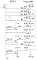
- the sub-module CP-A assigned to the switching control structure level CP in the exemplary embodiment for the first ten devices of the group GR selected by the code number simultaneously sends command information BI for the effective connection of the respective loudspeaker in the digital terminal KE-D or the direct establishment of the connection to the separate loudspeaker LRs KE-A defined as the analog terminal KE-A.
- the number of command information sent at the same time must be selected so that the system is not overloaded. It can e.g. B. ten devices receive a call at the same time.
- the subgroups, to which the currently called devices belong, are also stored in the memory area AS as corresponding information Za.
- a counter PZ also implemented as a software solution, corresponding to the calls VA sent out at the same time as the calls for the exemplary embodiment assumed value "10".
- the ten devices called up by the message VA1 ... VA10 are devices which were identified as being in the "free state” by the corresponding control by the switching control of the system.
- a called device sends a feedback An to the corresponding module of the line technology structure level DH
- the message Ans generated there generates an acknowledgment information ZRS in the switching control structure level.
- the connection establishment procedure is initiated for a digital terminal and the connection is established.
- the receipt information is generated when the connection is established in the line structure level DH.
- the counter PZ is reset by one count value with each receipt information. If, for example, return information arrives first from the device KE-D-B1, the acknowledgment information ZRS ... B1 is formed therefrom.
- the sub-module CP-A which is responsible for the subscriber A intending to make an announcement, causes the transmission of a sound signal TS to the respectively called digital terminal, by which the subscriber in question is informed about the connection of the loudspeaker in the terminal.
- command information BI is transmitted in the manner described to the next free device KE-D-B1 in the zone currently being addressed.
- the counter value is increased by the value "1", so that the number "10" is reached again for the devices called up at the same time.
- the next free device is prompted in the manner described to carry out the effective connection of the loudspeaker.
- an attention sign for example in the form of a specific audible tone Tsg, is transmitted to the originating device KE-DA. This then informs the subscriber concerned that the intended announcement can be made. Via the activated loudspeaker, this announcement affects all devices that are represented by the group GR ... defined with the selected key figure.
- the target address data of those devices are determined with the help of the database access procedures, which are provided for a collective announcement via the group-specific code number KZ.
- the point in time at which the loudspeakers of all the addressed devices KE-D-B1 ... KE-D-Bg were activated can be determined. Due to the permanent data stored in the memory area KD of the database, the group information defined by the selected key figure can be quickly assigned to the respective connections to be set up.
- the subgroups Z ... addressed overall are identified in the working memory AS (FIG. 2) by a corresponding marking bit MB.
Description
Die Erfindung betrifft ein Verfahren zur Herstellung einer Verbindung zwischen einem Ursprungs-Kommunikationsgerät mit einer Mehrzahl von Geräten in Form von separaten Lautsprechern und/oder von Lautsprecher aufweisenden Kommunikationsendgeräten, die jeweils an die programmgesteuerte Kommunikationsanlage angeschlossen sind, zum Zwecke einer von einer Bedienperson des Ursprungs-Kommunikationsgerätes gleichzeitig für diese Mehrzahl von Geräten jeweils zur Ausgabe über den aktivierten Lautsprecher bestimmten Durchsage, wobei die Kommunikationsanlage u. a. gerätebezogene Einheiten zur signalisierungsartindividuellen Anschaltung der Geräte, ein Koppelnetz zum Durchschalten der Verbindungswege und ein zur zentralen Steuerung der Kommunikationsanlage dienendes programmierbares digitales Rechnersystem aufweist, mit mindestens einem Systemspeicher zur Speicherung von Programmodulen und von Daten, und wobei die digitalen Signalisierungsinformationen über einen Signalisierungskanal und die Sprachinformationen über einen Sprachkanal über die Anschlußleitung übermittelt werden.The invention relates to a method for establishing a connection between a source communication device with a plurality of devices in the form of separate loudspeakers and / or communication terminals having loudspeakers, each of which is connected to the program-controlled communication system, for the purpose of being used by an operator of origin. Communication device simultaneously for this plurality of devices each for the announcement determined via the activated speaker, the communication system u. a. has device-related units for signaling-specific connection of the devices, a coupling network for switching through the connection paths and a programmable digital computer system used for central control of the communication system, with at least one system memory for storing program modules and data, and wherein the digital signaling information via a signaling channel and the voice information can be transmitted via a voice channel via the connecting line.
Die neuzeitlichen digitalen rechnergesteuerten Kommunikationsvermittlungsanlagen lassen den Einsatz von unterschiedlichen Kommunikationsendgeräten zu. Diese können sich also in ihrer Anschlußart und gegebenenfalls in den ihnen zugrundeliegenden Wahlverfahren unterscheiden. So dienen beispielsweise digitale Teilnehmeranschlußbaugruppen dem Anschluß von digitalen Kommunikationsendgeräten. Analoge Kommunikationsendgeräte sind über "analoge Anschlußtechnik" angeschlossen. Die zugrundeliegende Kommunikationsvermittlungsanlage besteht im Prinzip aus einer Vielzahl vermittlungstechnischer Funktionseinheiten und einem programmierbaren digitalen Rechensystem, das diese Funktionseinheiten steuert und alle vermittlungstechnischen Abläufe überwacht. Zu diesem Zweck wird das Rechensystem mit Informationen über den Betriebszustand der Funktionseinheiten und über Zustandsänderungen, insbesondere über Eingaben an den angeschlossenen Endgeräten, informiert. Es kann deshalb bei Bedarf umgehend entsprechende Steueranweisungen und Meldungen erstellen und ausgeben.The modern digital computer-controlled communication switching systems allow the use of different communication terminals. These can therefore differ in their type of connection and, if necessary, in the dialing procedure on which they are based. For example, digital subscriber line modules are used to connect digital communication terminals. Analog communication terminals are connected via "analog connection technology". The underlying communication switching system consists in principle of a large number of switching-related functional units and a programmable digital computer system that controls these functional units and all switching-related ones Processes monitored. For this purpose, the computing system is informed with information about the operating state of the functional units and about changes in state, in particular about entries on the connected terminal devices. If necessary, it can therefore immediately create and output appropriate control instructions and messages.
Derartige Kommunikationsvermittlungsanlagen, insbesondere Fernsprechnebenstellenanlagen, sind neben der eigentlichen Vermittlungssteuerung auch zu einer Steuerung bzw. Realisierung zusätzlicher, über den eigentlichen Vermittlungsvorgang hinausgehender Steuervorgänge befähigt. Solche zusätzlichen Funktionen werden im allgemeinen als Leistungsmerkmale bezeichnet, wobei insbesondere für den Kommunikationsdienst "Sprache" eine große Zahl unterschiedlicher Leistungsmerkmale bekannt ist. Derartige Leistungmerkmale können entweder bei Belegen der Vermittlungseinrichtung oder aber während einer bereits bestehenden Gesprächsverbindung eingeleitet werden. Dies kann beispielsweise durch Wahl bestimmter Kennziffern bzw. Kennziffernkombinationen und/oder durch die Betätigung sogenannter Funktionstasten erfolgen. Zu solchen Leistungsmerkmalen zählen beispielsweise akustische Hinweise für wartende Teilnehmer, die Darstellung von Bedienerhinweisen auf einer optischen Anzeigeeinrichtung und das unmittelbare Ansprechen eines angewählten Teilnehmers. Hierzu hat ein Teilnehmer die Möglichkeit, den am Endgerät des gewünschten Teilnehmers zum Zwecke des Freisprechens neben dem Handapparat vorhandenen Lautsprecher wirksam zu schalten. Es ist vorgesehen, daß eine derartige Wirksamschaltung des vorhandenen Lautsprechers von einem Teilnehmer auch an einer Mehrzahl von angeschlossenen Endgeräten vorgenommen werden kann. Über die aufgebauten Verbindungen kann dann gleichzeitig durch diesen Teilnehmer eine Durchsage an die betreffenden anderen Teilnehmer erfolgen. Eine denkbare Lösungsmöglichkeit besteht darin, daß der Verbindungsaufbau zu den in Frage kommenden Geräten nacheinander erfolgt. Beginnend mit dem ersten der für eine derartige Sammeldurchsage vorgesehenen Geräte wird nach dem Aussenden einer Befehlsinformation für die wirksame Anschaltung des Lautsprechers zunächst das Eintreffen der diese Anschaltung bestätigenden Rückmeldung die Verbindung durchgeschaltet und die Verbindung zum nächsten Gerät der vorgesehenen Gerätereihe aufgebaut. Nach jedem Empfang einer von einem Gerät abgesetzten Rückmeldung wird in gleicher Weise dem nächste Verbindungsaufbau veranlaßt. Dies setzt sich dann sukzessive bis zum letzten für diesen eingeleiteten Durchsagevorgang vorbestimmten Geräte fort. Bei einem solchen denkbaren Ablauf addieren sich die systembedingten Laufzeiten, so daß insbesondere bei einer Vielzahl von anzusprechenden Geräten eine unerwünscht große Zeitspanne beansprucht wird, bis die beabsichtigte Durchsage vorgenommen werden kann. Je nach Anzahl der Geräte ergeben sich zweistellige Sekundenwerte, wobei eine solche Wartezeit von demjenigen, der eine Durchsage beabsichtigt, als unangenehm empfunden werden würde. Darüberhinaus ist ein solcher Ablauf mit verhältnismäßig aufwendigen leistungsmerkmalsspezifischen Programmprozeduren verknüpft, die auch Konsequenzen für die eigentlichen Vermittlungsprozeduren haben.In addition to the actual switching control, such communication switching systems, in particular telephone private branch exchanges, are also capable of controlling or realizing additional control processes that go beyond the actual switching process. Such additional functions are generally referred to as performance features, a large number of different performance features being known in particular for the “voice” communication service. Such features can be initiated either when the switching device is busy or during an existing call. This can be done, for example, by selecting certain code numbers or code number combinations and / or by pressing so-called function keys. Such features include, for example, acoustic information for waiting participants, the display of operator information on an optical display device and the direct response of a selected participant. For this purpose, a subscriber has the option of activating the loudspeaker present on the terminal of the desired subscriber next to the handset for the purpose of hands-free calling. It is envisaged that such activation of the existing loudspeaker can also be carried out by a subscriber on a plurality of connected terminals. This subscriber can then simultaneously make an announcement to the other subscribers concerned via the established connections. A conceivable solution is that the connection to the devices in question is established one after the other. Starting with the first of the devices provided for such a collective announcement, after sending out command information for the effective connection of the loudspeaker first the arrival of the feedback confirming this connection is switched through the connection and the connection to the next device of the intended device series is established. After each receipt of a feedback sent by a device, the next connection establishment is initiated in the same way. This then continues successively until the last device predetermined for this announcement process initiated. With such a conceivable sequence, the system-related runtimes add up, so that an undesirably large amount of time is required, in particular in the case of a large number of devices to be addressed, before the intended announcement can be made. Depending on the number of devices, there are two-digit second values, such a waiting time would be perceived as uncomfortable by those who intend to make an announcement. In addition, such a process is linked to relatively complex performance feature-specific program procedures, which also have consequences for the actual switching procedures.
Der Erfindung liegt die Aufgabe zugrunde, ein Verfahren anzugeben, bei dem mit einfachen Steuerprozeduren eine gleichzeitige Durchsage eines Teilnehmers an eine Vielzahl von Geräten möglich ist und bei dem weiterhin die Zeitspanne zwischen der Aktivierung des Leistungsmerkmals "Sammeldurchsage" und der tatsächlichen Anschaltung der Gesamtheit der anzusprechenden Geräte minimiert ist. Diese Aufgabe wird ausgehend von den im Oberbegriff genannten Merkmalen dadurch gelöst, daß aus der Gruppe der bedarfsweise für eine Durchsage heranzuziehenden und im Systemspeicher abgelegten Geräten aufgrund der am Ursprungs-Kommunikationsgerät durch die Bedienperson vorgenommenen und zumindest den Dienst kennzeichnenden Eingabe zunächst eine festgelegte begrenzte maximale Anzahl von Geräten, für die keine Kommunikationsbeziehung besteht, aufgerufen werden, in dem durch das Rechnersystem die gleichzeitige Übermittlung jeweils einer Befehlsinformation für die Aktivierung des jeweiligen Lautsprechers über den Signalisierungskanal veranlaßt wird, daß jede vorbereitend erfolgte Aktivierung des Lautsprechers durch eine das aufgerufene Gerät kennzeichnende und von ihm ausgesendete Information als Quittungsinformation der Rechnersteuerung zurückgemeldet wird, daß daraufhin die Verbindungsaufbauprozedur eingeleitet und die Verbindung zu dem betreffenden Gerät hergestellt wird, und daß aufgrund jeder empfangenen Quittungsinformation die Ubermittlung der Befehlsinformation zu dem jeweils in der vorgegebenen Reihenfolge nächsten freien Gerät der Gruppe veranlaßt wird, und daß dieses jeweils solange initiiert wird, bis diese maximale Anzahl von aufzurufenden Geräten erneut erreicht ist, daß in dieser Weise diese Aufrufe kontinuierlich fortgesetzt werden und daß aufgrund der Quittungsinformation für das letzte Gerät der Gruppe ein die Bedienperson über die erfolgte Aktivierung aller Geräte der Gruppe informierendes Aufmerksamkeitszeichen zu dem Ursprungs-Kommunikationsgerät übertragen wird.The invention has for its object to provide a method in which a simultaneous announcement of a subscriber to a variety of devices is possible with simple control procedures and in which the time period between the activation of the feature "collective announcement" and the actual connection of all of those to be addressed Devices is minimized. This object is achieved on the basis of the features mentioned in the preamble in that from the group of devices which are required for an announcement and are stored in the system memory, on the basis of the input made by the operator on the original communication device and at least characterizing the service, a fixed, limited maximum number from devices for which there is no communication relationship can be called, in which the computer system prompts the simultaneous transmission of command information for the activation of the respective loudspeaker via the signaling channel that any preparatory activation of the loudspeaker by one of the called devices identifying and emitting information is reported back to the computer control as acknowledgment information, that the connection establishment procedure is then initiated and the connection to the device in question is established, and that, based on each receipt information received, the command information is transmitted to the next free device in the group in the specified sequence is initiated, and that this is always initiated until this maximum number of devices to be called is reached again, that these calls are continuously continued in this way, and that, based on the receipt information for the last device in the group, the operator is informed about the activation of all Devices of the group of informational attention signs are transmitted to the originating communication device.
Die Anzahl derjenigen Geräte, die sich jeweils im Zustand des "Aufrufes" befinden, wird so gewählt, daß im Hinblick auf die übrigen im System ablaufenden Vorgänge eine dynamische Überlastung sicher vermieden wird. Sinnvollerweise wählt man eine solche Anzahl, die für den Verbindungsaufbau insgesamt eine Zeit erfordern, die angenähert derjenigen entspricht, in der eine Quittungsinformation von einem ersten dieser gleichzeitig angesprochenen Geräte empfangen wird. Es ergibt sich somit gegenüber einer seriellen Behandlung der Vorteil, daß sich die Zeitdauer, die notwendig ist, um alle anzusprechenden Geräte zu aktivieren, um das Verhältnis dieser maximalen Geräteanzahl der "Startgruppe" verringert.The number of devices that are in the "call" state is selected so that a dynamic overload is reliably avoided with regard to the other processes taking place in the system. It makes sense to choose a number that requires a total time to establish the connection that approximately corresponds to that in which acknowledgment information is received by a first of these simultaneously addressed devices. This has the advantage over a serial treatment that the time required to activate all devices to be addressed is reduced by the ratio of this maximum number of devices of the "start group".
Nach einer Weiterbildung des Verfahrens gemäß der Erfindung sind mehrere Gruppen von Geräten vorgesehen, die ihrerseits aus höchstens eine vorgegebene Zahl von Geräten aufweisenden Untergruppen gebildet sind. Diese sind wahlweise in unterschiedlichen sinnvollen Kombinationen zu der jeweiligen Gruppe zusammengefaßt und in dieser vorgenommenen Zuordnung im Systemspeicher abgespeichert. Für eine bedarfsweise Sammeldurchsage sind die nach bestimmten Kriterien einer jeden Gruppe zugeordneten Geräte durch eine jeweils individuell zugeordnete Eingabe von der Bedienperson selektiv aufrufbar. Es können also die vorhandenen Geräte nach unterschiedlichsten Gesichtspunkten zu derartigen Gruppen zusammengefaßt werden. Eine Untergruppe kann demnach in einer oder auch in mehreren Gruppen eingeordnet sein. Die gewählten Zuordnungen sind in beliebiger Mischung möglich und lassen sich problemlos ändern.According to a further development of the method according to the invention, several groups of devices are provided, which in turn are formed from subgroups having at most a predetermined number of devices. These are optionally combined in different meaningful combinations to form the respective group and stored in the system memory in this assignment. For a collective announcement as required, the devices assigned to each group according to certain criteria are individually assigned Input can be selectively called up by the operator. The existing devices can thus be combined into such groups according to the most varied of criteria. A subgroup can therefore be classified in one or more groups. The selected assignments are possible in any mix and can be changed easily.
Gemäß einer Weiterbildung des erfindungsgemäßen Verfahrens wird durch einen Zähler kontrolliert, daß die maximale Anzahl der jeweils aufgerufenen Geräte nicht überschritten wird. Dieser in einfacher Weise durch eine Software-Lösung zu realisierende Zähler wird mit jedem initiierten Quittungszeichen um einen Zählwert zurückgestellt und mit jeder übermittelten Befehlsinformation um einen Zählwert erhöht, wobei die der vorgegebenen maximalen Anzahl der jeweils angesprochenen Geräte entsprechende Zählerstellung nicht überschritten wird. Mit der Initialisierung des Leistungsmerkmals "Sammeldurchsage" wird der Zähler in die der Startgruppe zahlenmäßig entsprechende Stellung gebracht und das Aussenden der Befehlsinformationen so gesteuert, daß dieser die 'ahl der gleichzeitige Aufrufe bestimmender Wert bis zum Aufruf des letzten Gerätes der Gruppe beibehalten wird.According to a development of the method according to the invention, a counter checks that the maximum number of devices called up is not exceeded. This counter, which can be implemented in a simple manner by a software solution, is reset by a count value with each initiated acknowledgment character and increased by a count value with each transmitted command information, the counter position corresponding to the predetermined maximum number of the respective devices addressed not being exceeded. With the initialization of the "collective announcement" feature, the counter is brought into the position corresponding to the number of the start group and the transmission of the command information is controlled in such a way that this value which determines the number of simultaneous calls is retained until the last device in the group is called.
Ausgehend von einem besonderen Vermittlungszustand, in dem eine ankommende externe Verbindung durch den diese Verbindung abfragenden Teilnehmer in den Wartezustand übergeführt wurde, sind in gleicher Weise durch eine zusätzlich diesen besonderen Vermittlungszustand kennzeichnende gruppenindividuelle Eingabe aus den verschiedenen Gruppen die Geräte jeweils einer Gruppe in der vorstehend genannten Weise aufrufbar. Derjenige Teilnehmer, der sich daraufhin durch Eingabe einer bestimmten Codeinformation als angesprochener Teilnehmer meldet, kann dann unmittelbar in eine Gesprächsverbindung mit dem wartenden Teilnehmer eintreten. Er wird in diesem besonders gekennzeichneten Zustand durch die zentrale Steuerung zu dieser Verbindung durchgeschaltet.Starting from a special switching state, in which an incoming external connection has been transferred to the waiting state by the subscriber querying this connection, in the same way, by additionally entering this special switching state, group-specific input from the different groups is the devices of each group in the above-mentioned Callable way. The subscriber who then registers as a addressed subscriber by entering a certain code information can then immediately initiate a call with the waiting subscriber. In this specially marked state, it is switched through to this connection by the central controller.
In diesem speziellen Falle werden also die für eine Sammeldurchsage vorgesehenen Prozeduren (Programme) unverändert verwendet, da die entsprechenden Speicherbereiche durch die eingegebene Codeinformation unmittelbar angesteuert werden.In this special case, the procedures (programs) intended for a collective announcement are used unchanged, since the corresponding memory areas are directly controlled by the code information entered.
Eine Weiterbildung des Verfahrens sieht vor, daß sowohl die erfolgte Aktivierung eines Lautsprechers in einem Endgerät als auch die Aktivierung aller freien Geräte der jeweils aufgerufenen Gruppe durch ein optisches oder ein akustisches Aufmerksamkeitszeichen angezeigt wird. Die einzelnen Teilnehmer sind also vorab über eine nachfolgende Durchsage informiert und die Bedienperson, die diese Durchsage beabsichtigt, wird darüber unterrichtet, daß mit dieser Durchsage begonnen werden kann.A further development of the method provides that the activation of a loudspeaker in a terminal as well as the activation of all free devices of the group called up is indicated by an optical or an acoustic attention sign. The individual subscribers are therefore informed in advance of a subsequent announcement and the operator who intends to make this announcement is informed that this announcement can be started.
Die Erfindung wird im folgenden anhand eines schematisch dargestellten Ausführungsbeispiels erläutert.The invention is explained below with reference to a schematically illustrated embodiment.
Dabei zeigen
- FIG 1
- ein Blockschaltbild einer Kommunikationsvermittlungsanlage einschließlich dem Kommunikationsendgerätebereich,
- FIG 2
- die Steuerstruktur einer digitalen Kommunikationsvermittlungsanlage, die der Durchführung des Verfahrens gemäß der Erfindung dient, und
- FIG 3
- ein Ablaufdiagramm der dem Verfahren zugrundeliegenden Meldungen.
- FIG. 1
- 2 shows a block diagram of a communication switching system including the communication terminal area,
- FIG 2
- the control structure of a digital communication switching system which is used to carry out the method according to the invention, and
- FIG 3
- a flow chart of the messages underlying the method.
Zentraler Bestandteil der in der FIG 1 schematisch dargestellten digitalen Kommunikationsanlage KA ist ein Koppelfeld SN, über das Kommunikationsendgeräte - schematisch angedeutet durch KE-D und KE-A - miteinander bzw. mit zu einer öffentlichen Vermittlungsanlage oder zu anderen Nebenstellenanlagen führenden Leitungen VL verbindbar sind. Das zentrale Koppelfeld SN steht unter dem Steuereinfluß einer zentralen Anlagensteuerung ASt, das die hierarchisch oberste Strukturebene der Kommunikationsanlage darstellt. Diese Strukturebene wird durch einen zentralen Steuerprozessor DP gebildet, der das Zusammenwirken aller Bausteine und Module der Kommunikationsanlage KA koordiniert. Neben einer takterzeugenden Einrichtung PG ist die Anlagensteuerung weiterhin mit einer vorgeschalteten Zugangssteuerung DCL und einem Speicher MEM ausgestattet. Die Einheit DCL dient als Schnittstelle zur Peripherie, die als 'Master' einer HDLC-Verbindung die Protokollbehandlung auf einem Signalisierungskanal durchführt. In dem Speicher MEM sind beispielsweise die vermittlungstechnische Datenbasis und alle vermittlungstechnisch relevanten Programme und die dazugehörigen Daten gespeichert. Wesentliche Funktionen des zentralen Steuerprozessors DP sind also die Speicherung und anforderungsgerechte Abarbeitung von vermittlungstechnischen Programmen und die Steuerung und Überwachung des lokalen Busses LB, an den peripheriezugewandt die Einheiten DCL und das Koppelfeld SN angeschlossen sind. Zusätzliche übliche Funktionen des zentralen Datenprozessors DP sind beispielsweise betriebstechnische Abwicklungen und sicherheitstechnische Anzeigen.A central component of the digital communication system KA shown schematically in FIG. 1 is a switching network SN, via which communication terminals - indicated schematically by KE-D and KE-A - can be connected to one another or to lines VL leading to a public switching system or to other private branch exchanges. The central switching network SN is under the control of a central system control ASt, which represents the top hierarchical level of the communication system. This structure level is formed by a central control processor DP, which coordinates the interaction of all modules and modules of the communication system KA. In addition to a clock-generating device PG, the system control is also equipped with an upstream access control DCL and a memory MEM. The unit DCL serves as an interface to the periphery, which, as the 'master' of an HDLC connection, carries out protocol handling on a signaling channel. For example, the switching database and all switching-relevant programs and the associated data are stored in the memory MEM. Essential functions of the central control processor DP are therefore the storage and processing of switching technology programs in accordance with requirements and the control and monitoring of the local bus LB, to which the units DCL and the switching network SN are connected, facing the periphery. Additional common functions of the central data processor DP are, for example, operational processing and safety-related displays.
Wesentlicher Bestandteil der Peripherie sind periphere Schnittstellen PS1...PSn, die teilnehmerbezogene Satzbaugruppen TS und leitungsbezogene Satzbaugruppen LS aufweisen. Diesen peripheren Schnittstellen PS1...PSn ist eine Schnittstellensteuerung LTUC zugeordnet. Diese steuert den Verbindungsaufbau zwischen den Kommunikationsendgeräten KE..., wobei hierfür ein programmtechnisch realisiertes Verbindungsaufbauverfahren vorgesehen ist. In den Schnittstellen PS sind die mit den Kommunikationsendgeräten KE die Signalisierungsprotokolle abwickelnden Verfahren bzw. Programmodule vorwiegend realisiert. Die der Berechtigungsprüfung hinsichtlich Dienste, Leistungsmerkmalen, usw., sowie der Verbindungssteuerung über das digitale zentrale Koppelfeld SN dienenden Verbindungsaufbauverfahren bzw. Programmodule sind in der zentralen Anlagensteuerung ASt implementiert.An essential part of the periphery are peripheral interfaces PS1 ... PSn, which have subscriber-related set modules TS and line-related set modules LS. An interface control LTUC is assigned to these peripheral interfaces PS1 ... PSn. This controls the establishment of the connection between the communication terminals KE ..., for which purpose a connection establishment method implemented in terms of programming is provided. The processes or program modules that handle the signaling protocols with the communication terminals KE are predominantly implemented in the interfaces PS. The connection establishment methods or program modules used to check the authorization with regard to services, features, etc., and to control the connection via the digital central switching network SN, are implemented in the central system controller ASt.
Die Peripherie ist ergänzt durch ein Modul SU, das der Versorgung der Kommunikationsvermittlungsanlage KA mit Signalisierungsinformationen und mit während des Haltezustandes von Verbindungen vorgenommenen Musikeinspielungen dient. Dieses Modul SU enthält außerdem signalisierungsunterstützende Einrichtungen sowie auch Testeinrichtungen. Dieses zusätzliche Modul ist in ähnlicher Weise wie die Schnittstellen PS über eine PCM-strukturierte Verbindung sowie über eine zur Übergabe und Aufnahme von Steuerinformationen dienende Übertragungsstrecke angeschaltet. Diese Informationen werden z. B. im standardisierten Übertragungsverfahren HDLC übermittelt.The periphery is supplemented by a module SU, which is used to supply the communication switching system KA with signaling information and with music recordings made while connections are on hold. This module SU also contains signaling-supporting devices and also test devices. This additional module is connected in a manner similar to the interfaces PS via a PCM-structured connection and via a transmission link used for transferring and receiving control information. This information is used e.g. B. in the standardized transmission method HDLC.
An die Kommunikationsanlage KA können neben digitalen Kommunikationsendgeräten KE-D auch herkömmliche Endgeräte KE-A mit analoger Übertragung jeweils über eine Anschlußleitung ASL angeschlossen werden. Dies erfolgt für eine jede periphere Schnittstelle PS für die digitalen Kommunikationsendgeräte KE-D über eine die entsprechende digitale Informationsübertragung beherrschende Satzbaugruppe TS-D und für die analogen Kommunikationsendgeräte durch eine entsprechend angepaßte Satzbaugruppe TS-A. Diese sind für jede Schnittstelle mehrfach vorhanden und dienen u. a. dazu, die unterschiedlichen Signalisierungsinformationen von den einzelnen Endgeräten und - bezogen auf die Satzbaugruppe LS - von anderen Netzen auf ein innerhalb der Kommunikationsanlage einheitlich verwendetes Format umzuwandeln. An einer jeden Satzbaugruppe TS sind jeweils eine Mehrzahl von Leitungsanschlüssen zugänglich.In addition to digital communication terminals KE-D, conventional terminal devices KE-A with analog transmission can each be connected to the communication system KA via a connecting line ASL. This is done for each peripheral interface PS for the digital communication terminals KE-D via a set module TS-D that controls the corresponding digital information transmission and for the analog communication terminals through a correspondingly adapted set module TS-A. These are available several times for each interface and serve u. a. to convert the different signaling information from the individual end devices and - based on the set module LS - from other networks to a format used uniformly within the communication system. A plurality of line connections are accessible on each set assembly TS.
Ein digitales Kommunikationsendgerät, das beispielsweise ausschließlich ein Sprachendgerät darstellt, ist in der Regel mit einem Display DL, einer Wähltastatur WT und einem Satz von Funktionstasten FT ausgestattet. Um ein Freisprechen zu ermöglichen, ist im Endgerät ein Mikrophon MI und ein Lautsprecher LR angeordnet. Neben analogen Fernsprechendgeräten KE-A kann auch anstelle eines solchen Gerätes ein Lautsprecher LRs, der beispielsweise als Raumlautsprecher eingesetzt ist, über eine Anschlußleitung ASL an eine für derartige analoge Anschlüsse zuständige Satzbaugruppe TS-A angeschlossen sein.A digital communication terminal, which for example only represents a voice terminal, is usually equipped with a display DL, a dialing keyboard WT and a set of function keys FT. In order to enable hands-free speaking, a microphone MI and a loudspeaker LR are arranged in the terminal. In addition to analog telephone terminals KE-A, a loudspeaker LR, which is used, for example, as a room loudspeaker, can also be connected via a connecting line ASL to a set module TS-A which is responsible for such analog connections, instead of such a device.
Es ist in der Anlage möglich, von einem Bedien- oder Vermittlungsplatz oder auch von einem beliebigen Teilnehmerendgerät aus eine sogenannte Sammeldurchsage vorzunehmen. In einem solchen Fall wird von einer Bedienperson bzw. einem internen Fernsprechteilnehmer die wirksame Anschaltung der in vorab definierten Fernsprechendgeräten vorhandenen Lautsprecher LR als auch von vorhandenen separaten Lautsprechern LRs initiiert. Die jeweils anzusprechenden Geräte in Form von Fernsprechendgeräten oder von separaten Lautsprechern sind in verschiedenen Gruppen GR1...GRn zusammengefaßt. Die definitionsgemäß einer Gruppe zugehörigen Geräte sind selbst wiederum in einzelnen Untergruppen Z1...Zm geordnet. Eine jede dieser Untergruppen umfaßt eine maximale Anzahl von Geräten, beispielsweise von 20 Geräten. Ein Gerät kann - wie bereits erwähnt - z. B. ein digitales Fernsprechendgerät KE-D oder einen separaten Lautsprecher LRs darstellen. Es kann jede Untergruppe einer oder auch mehreren Hauptgruppen GR... zugeordnet werden. Die einzelnen Untergruppen und Hauptgruppen können nach für den Anlagenbetreiber sinnvollen Gesichtspunkten ausgewählt werden. Durch die Gliederung in Untergruppen, aus denen sich dann wiederum eine Hauptgruppe zusammensetzt, sind die Möglichkeiten für das Ansprechen von Teilnehmern im Zusammenhang mit einer Sammeldurchsage sehr variabel zu gestalten. Diese Durchsage kann für eine jede Hauptgruppe durch die Eingabe einer dieser Gruppe jeweils individuell zugeordneten Kennzahl KZ von der Bedienperson initiiert werden.In the system, it is possible to make a so-called collective announcement from an operating or switching station or from any subscriber terminal. In such a case, an operator or an internal telephone subscriber initiates the effective connection of the loudspeakers LR present in predefined telephone telephones as well as of existing separate loudspeakers LRs. The devices to be addressed in the form of telephone devices or separate loudspeakers are combined in different groups GR1 ... GRn. The devices which by definition belong to a group are themselves arranged in individual sub-groups Z1 ... Zm. Each of these sub-groups comprises a maximum number of devices, for example 20 devices. As already mentioned, a device can e.g. B. represent a digital telephone device KE-D or a separate speaker LRs. Each subgroup can be assigned to one or more main groups GR ... The individual subgroups and main groups can be selected according to points of view that are meaningful for the system operator. The division into subgroups, which then in turn make up a main group, means that the options for addressing participants in connection with a collective announcement can be made very variable. This announcement can be initiated by the operator for each main group by entering a code number KZ individually assigned to this group.
Die kundenspezifisch festgelegten Zuordnungen der einzelnen an die Kommunikationsanlage KA angeschlossenen Geräte KE-D und KE-A zu der jeweiligen Gruppe sind gemäß der FIG 2 in einem die Kundendaten enthaltenen Permanentspeicherbereich KD der Datenbasis DB abgespeichert. In dieser Datenbasis sind auch alle vermittlungstechnisch relevanten Programme gespeichert. Sie kann beispielsweise im Speicher MEM der FIG 1 enthalten sein. Ein weiterer Speicherbereich in der Datenbasis DB kann beispielsweise ein Arbeitsspeicher AS des Rechnersystems ASt der Kommunikationsanlage sein, in dem die im Zusammenhang mit einer Sammeldurchsage entstehenden dynamischen Daten abgespeichert werden.The customer-specific assignments of the individual devices KE-D and KE-A connected to the communication system KA to the respective group are stored according to FIG. 2 in a permanent memory area KD of the database DB containing the customer data. All programs relevant to switching technology are also stored in this database. It can be contained, for example, in the memory MEM in FIG. 1. Another memory area in the database DB can be, for example, a working memory AS of the computer system ASt be the communication system in which the dynamic data arising in connection with a collective announcement are stored.
Die in der FIG 2 dargestellte Steuerstruktur der digitalen Kommunikationsanlage hat einen modularen Charakter und weist zwei hierarchische Ebenen der Programmsteuerung auf. Eine von ihnen dient mittels jeweils an eine Kommunikationsendgeräteart angepaßten Leitungstechnik-Programmodulen DH1, DH2...DHx (Device Handler) der Steuerung peripherer Geräte. Zu diesen zählen nicht nur die an die Peripherie angeschlossenen Kommunikationsendgeräte KE..., sondern auch zentrale schaltungstechnische Einrichtungen, wie Anschaltesätze und Koppelfeld. Jedes dieser Leitungstechnik-Programmodule DH bietet eine systemeinheitliche Schnittstelle zur Vermittlungstechnik-Strukturebene, die im vorliegenden Fall durch ein Vermittlungsprozedur-Programmmodul CP repräsentiert ist. In der Leitungstechnik-Strukturebene DH sind den einzelnen Endgerätearten zugeordnete, sogenannte Leitungstechnik-Programmodule DTE für digitale Endgeräte und ATE für analoge Endgeräte im Programmodul DH2 angedeutet. In der Vermittlungssteuerungs-Strukturebene sind Teilmodule für unterschiedliche Teilaufgaben der Verbindungssteuerung vorgesehen. Der Informationsaustausch zwischen der Leitungstechnik-Strukturebene und der Vermittlungstechnik-Strukturebene erfolgt mittels definierter Meldungen, die über eine Software-Busstruktur SWB übertragen werden. Diese kann als integraler Bestandteil des Betriebssystems des Kommunikationsvermittlungsanlagenrechners angesehen werden. Das Vermittlungssteuerungs-Programmodul CP, die Leitungstechnik-Programmodule DH1, DH2...DHy und der Softwarebus SWB haben mittels Datenbasis-Zugriffsroutinen DBAR Zugang zur Datenbasis DB der gesamten Kommunikationsanlage. Neben dem Vermittlungsprozedur-Programmodul CP sind weitere Module vorgesehen, von denen mit AMA beispielhaft die Betriebstechnik-Programmodule angedeutet sind. Diese dienen zur Abwicklung von betriebstechnischen Aufgaben. Zumindest einem Teil von ihnen ist gleichfalls über definierte Datenbasis-Zugriffsroutinen die Datenbasis DB zugänglich.The control structure of the digital communication system shown in FIG. 2 has a modular character and has two hierarchical levels of program control. One of them is used to control peripheral devices by means of line technology program modules DH1, DH2 ... DHx (device handler), each adapted to a type of communication terminal. These include not only the KE ... communication terminals connected to the periphery, but also central circuit technology devices, such as connection kits and switching matrix. Each of these line technology program modules DH offers a system-uniform interface to the switching technology structure level, which in the present case is represented by a switching procedure program module CP. In the line technology structure level DH, so-called line technology program modules DTE for digital end devices and ATE for analog end devices assigned to the individual terminal types are indicated in the program module DH2. In the switching control structure level, sub-modules are provided for different sub-tasks of connection control. The exchange of information between the line technology structure level and the switching technology structure level takes place by means of defined messages which are transmitted via a software bus structure SWB. This can be viewed as an integral part of the operating system of the communication switching system computer. The switching control program module CP, the line technology program modules DH1, DH2 ... DHy and the software bus SWB have access to the database DB of the entire communication system by means of database access routines DBAR. In addition to the switching procedure program module CP, further modules are provided, of which the operating technology program modules are indicated by way of example with AMA. These are used to handle operational tasks. The database DB is also accessible to at least some of them via defined database access routines.
Die Leitungstechnik-Programmodule DH1, DH2...DHy sind kommunikationsendgeräteartenspezifisch so ausgebildet, daß sie jeweils das Signalisierungsverfahren und die Benutzeroberfläche der entsprechenden Kommunikationsendgeräteart steuern. Das Vermittlungsprozedur-Programmodul CP ist kommunikationsendgeräteartenunabhängig und kommunikationsdiensteunabhängig derartig strukturiert, daß es den maximalen Funktionsumfang der peripheren Geräte und Einrichtungen steuerungstechnisch beherrscht. Die Aufgaben des Vermittlungsprozedur-Programmoduls CP umfassen also die für die Steuerung des Verbindungsaufbaus und -abbaus notwendigen Teilprozesse der gesamten Vermittlungsprozedur. So werden z. B. Berechtigungen geprüft und Wahlkontrollen durchgeführt. Es erfolgt auch eine Signalisierung von vermittlungstechnischen Zuständen zwischen den Kommunikationsendgeräten und es ist ein Aktivieren und Deaktivieren von Vermittlungstechnik-Leistungsmerkmalen aus den verschiedenen vermittlungstechnischen Zuständen heraus durchführbar.The line technology program modules DH1, DH2 ... DHy are designed specifically for communication terminal types in such a way that they each control the signaling method and the user interface of the corresponding communication terminal type. The switching procedure program module CP is structured independently of the type of communication terminal and is independent of the communication service in such a way that it controls the maximum range of functions of the peripheral devices and devices in terms of control technology. The tasks of the switching procedure program module CP thus include the subprocesses of the entire switching procedure necessary for controlling the connection establishment and clearing down. So z. B. Authorizations checked and election checks carried out. There is also a signaling of switching technology states between the communication terminals and it is possible to activate and deactivate switching technology performance features from the various switching technology states.
Wesentlicher Bestandteil der Vermittlungstechnik-Strukturebene CP ist das Vermittlungsprozedur-Programmodul CPTL (Call Processing Trunk Line), das wiederum in unterschiedliche Teilmodule aufgeteilt ist. Die vermittlungstechnischen Steuerprozeduren werden von einer in der FIG 2 innerhalb der Einheit CPTL schematisch dargestellten Kommunikationsanlagensteuerung DP durchgeführt. Stellvertretend für die in der Anlage vorgesehenen Leistungsmerkmal-Programmodule ist das Modul LM und das im Zusammenhang mit einer Sammeldurchsage vorgesehene Modul PC gezeigt. Zu den Leistungsmerkmal-Programmodulen ist auch ein Netzwerksteuer-Programmodul NWC zu zählen, mit dem die gesamte logische Verbindungsspeichersteuerung und die Steuerung des Koppelfeldes SN realisiert wird.An essential component of the switching technology structure level CP is the switching procedure program module CPTL (Call Processing Trunk Line), which in turn is divided into different sub-modules. The switching control procedures are carried out by a communication system controller DP shown schematically in FIG. 2 within the unit CPTL. The LM module and the PC module provided in connection with a collective announcement are shown as representative of the feature program modules provided in the system. The performance feature program modules also include a network control program module NWC, with which the entire logical connection memory control and the control of the switching network SN are implemented.
Die prinzipielle Struktur der bei einem durch das Programmodul PC abzuwickelnden Sammeldurchsage-Vorgang zugeordneten permanenten und dynamischen Daten ist in der Datenbasis DB angedeutet. In dem Teilbereich KD handelt es sich um diejenigen permanenten Daten, die während eines durch ein Kommunikationsendgerät initiierten Sammeldurchsage abgefragt und zumindest teilweise in den Arbeitsspeicherbereich AS der Datenbasis DB übernommen werden.The basic structure of the permanent and dynamic data associated with a collective announcement process to be processed by the program module PC is indicated in the database DB. In the sub-area KD there are those permanent data which are queried during a collective announcement initiated by a communication terminal and are at least partially transferred to the working memory area AS of the database DB.
Die Permanentspeicher KD der Datenbasis DB enthalten neben den übrigen Systemkonfigurationsdaten auch die im Zusammenhang mit einer durchzuführenden Sammeldurchsage relevanten Daten. Es ist dort abgespeichert, welches Kennzeichen KZ jeweils einer der nach bestimmten Gesichtspunkten aus den Untergruppen gebildeten Hauptgruppen GR1...GRn zugeordnet ist. Weiterhin sind diejenigen Untergruppen Z... abgespeichert, die jeweils zu einer Hauptgruppe GR gehören. Es können beispielsweise acht Hauptgruppen und acht Untergruppen gebildet sein. Es kann dabei eine der Untergruppen Z1...Zm einer oder auch mehreren Hauptgruppen zugeordnet werden. Für jede der einzelnen Untergruppen Z1...Zm ist eine Liste derjenigen Geräte G... abgespeichert, die jeweils zu dieser Untergruppe Z... gehören. So sollen beispielsweise die Geräte G1r...G1x die Untergruppe Z1 bilden. Für "x" kann beispielsweise ein maximaler Wert von "20" festgelegt sein. Für die übrigen Untergruppen sind dann jeweils die zugehörigen Geräte gleichfalls listenmäßig abgelegt. So gehören z. B. zur Untergruppe Zm die Geräte Gs1...Gsy, wobei "y" beispielsweise Werte von eins bis 20 annehmen kann. In einer Hauptgruppe könnten also in dem gewählten Ausführungsbeispiel mit acht Untergruppen und maximal 20 Geräten für jede dieser Untergruppen in einer Hauptgruppe maximal insgesamt 160 Geräte zusammengefaßt sein.In addition to the other system configuration data, the permanent memories KD of the database DB also contain the data relevant in connection with a collective announcement to be carried out. It is stored there which identifier KZ is assigned to one of the main groups GR1 ... GRn formed from the subgroups according to certain criteria. Furthermore, those subgroups Z ... that each belong to a main group GR are stored. For example, eight main groups and eight subgroups can be formed. One of the subgroups Z1 ... Zm can be assigned to one or more main groups. For each of the individual subgroups Z1 ... Zm, a list of those devices G ... that each belong to this subgroup Z ... is stored. For example, devices G1r ... G1x should form subgroup Z1. For example, a maximum value of "20" can be set for "x". For the other subgroups, the associated devices are then also stored in lists. So include B. to the subgroup Zm the devices Gs1 ... Gsy, where "y" can assume values from one to 20, for example. In a main group, a maximum of 160 devices could therefore be combined in a main group in the selected exemplary embodiment with eight subgroups and a maximum of 20 devices for each of these subgroups.
Grundsätzlich wird bei jedem Einleiten einer Verbindungsaufbauprozedur durch ein Kommunikationsendgerät in der permanente Daten speichernden Datenbasis ein diesem Gerät zugeordneter Speicherbereich abgefragt. Im Rahmen dieser Abfrage wird das rufende Kommunikationsendgerät eindeutig identifiziert. Die darin abgespeicherten Dienste und Berechtigungen hinsichtlich benutzbarer Leistungsmerkmale werden gelesen und gegebenenfalls in einem dynamische Daten speichernden Speicherbereich der Datenbasis gespeichert. Weiterhin werden die darin enthaltenen physikalischen Funktionen, wie z. B. die verwendeten Endgeräteschnittstellen, gelesen und gespeichert. Diese Daten werden im Laufe des Verbindungsaufbaus und bei Einleiten vermittlungstechnischer Prozeduren bewertet bzw. abgefragt.Basically, each time a connection establishment procedure is initiated by a communication terminal, a memory area assigned to this device is queried in the database storing permanent data. In the context of this query, the calling communication terminal is clearly identified. The services and authorizations relating to usable performance features stored therein are read and, if necessary, stored in a memory area of the database which stores dynamic data. Furthermore, the physical functions contained therein, such as. B. the terminal interfaces used, read and saved. This data is evaluated or queried in the course of establishing a connection and when initiating switching procedures.
Beabsichtigt nun ein Teilnehmer, eine Sammeldurchsage zu machen, so wählt er die Kennzahl KZ... der von ihm hierzu vorgesehenen Hauptgruppe. Diese Kennzahl kann sowohl die Gruppe als auch das Leistungsmerkmal "Sammeldurchsage" definieren. Es könnte auch hierfür die Kombination aus der Betätigung einer Funktionstaste und der nachfolgenden Einwahl einer Kennzahl vorgesehen sein. Es wird daraufhin der dem Leistungsmerkmal "Sammeldurchsage" zugeordnete Speicherbereich abgefragt. Aufgrund der im Speicherbereich AS eingeschriebenen Informationen erkennt die Steuerung, welche Untergruppen und welche Geräte innerhalb dieser Untergruppen angesprochen werden müssen. Im Zusammenwirken mit dem Netzwerksteuer-Programmodul NWC werden nun Verbindungen zwischen dem eine Sammeldurchsage beabsichtigenden Teilnehmer KE-D-A und den festgelegten Geräten aufgebaut. Wie dem Ablaufdiagramm der Meldungen nach der FIG 3 zu entnehmen ist, wird durch das der Vermittlungssteuerungs-Strukturebene CP zugeordnete Teilmodul CP-A im Ausführungsbeispiel für die ersten zehn Geräte der durch die Kennzahl ausgewählten Gruppe GR die gleichzeitige Absendung einer Befehlsinformation BI für die wirksame Anschaltung des jeweiligen Lautsprechers im digitalen Endgerät KE-D bzw. die unmittelbare Verbindungsherstellung zu dem als analoges Endgerät KE-A definierten separaten Lautsprecher LRs KE-A veranlaßt. Die Anzahl der gleichzeitig abgeschickten Befehlsinformationen ist so zu wählen, daß das System nicht überlastet ist. Es können z. B. zehn Geräte gleichzeitig einen Aufruf erhalten. Die Untergruppen, zu denen die jeweils aktuell aufgerufenen Geräte gehören, werden ebenfalls im Speicherbereich AS als entsprechende Information Za abgespeichert. Im Zusammenwirken mit dem bei einer Durchsage herangezogenen Programmodul PC wird ein ebenfalls als Software-Lösung realisierter Zähler PZ entsprechend den gleichzeitig ausgesendeten Aufrufen VA auf den für das Ausführungsbeispiel angenommen Wert "10" gestellt. Bei den jeweils durch die Meldung VA1...VA10 aufgerufenen zehn Geräten handelt es sich um Geräte, die bei der entsprechenden Prüfung durch die Vermittlungssteuerung des Systems als sich im "Freizustand" befindlich erkannt wurden.If a subscriber now intends to make a collective announcement, he dials the code KZ ... of the main group he intended for this purpose. This key figure can define both the group and the "collective announcement" feature. The combination of the actuation of a function key and the subsequent dialing in of a code could also be provided for this. The memory area assigned to the "collective announcement" feature is then queried. On the basis of the information written in the memory area AS, the controller recognizes which subgroups and which devices within these subgroups have to be addressed. In cooperation with the network control program module NWC, connections are now established between the subscriber KE-DA intending to make a broadcast announcement and the specified devices. As can be seen from the flow chart of the messages according to FIG. 3, the sub-module CP-A assigned to the switching control structure level CP in the exemplary embodiment for the first ten devices of the group GR selected by the code number simultaneously sends command information BI for the effective connection of the respective loudspeaker in the digital terminal KE-D or the direct establishment of the connection to the separate loudspeaker LRs KE-A defined as the analog terminal KE-A. The number of command information sent at the same time must be selected so that the system is not overloaded. It can e.g. B. ten devices receive a call at the same time. The subgroups, to which the currently called devices belong, are also stored in the memory area AS as corresponding information Za. In cooperation with the program module PC used in the event of an announcement, a counter PZ, also implemented as a software solution, corresponding to the calls VA sent out at the same time as the calls for the exemplary embodiment assumed value "10". The ten devices called up by the message VA1 ... VA10 are devices which were identified as being in the "free state" by the corresponding control by the switching control of the system.
Gibt ein aufgerufenes Gerät eine Rückmeldung An an das entsprechende Modul der Leitungstechnik-Strukturebene DH, so wird durch die dort generierte Meldung Ans in der Vermittlungssteuerungs-strukturebene eine Quittungsinformation ZRS generiert. Aufgrund jeder Quittungsinformation wird für ein digitales Endgerät die Verbindungsaufbauprozedur eingeleitet und die Verbindung hergestellt. Bei einem separaten Lautsprecher als aufgerufenes Gerät wird die Quittungsinformation mit der Verbindungsherstellung in der leitungstechnischen Strukturebene DH erzeugt. Weiterhin wird mit jeder Quittungsinformation der Zähler PZ um einen Zählwert zurückgestellt. Trifft also beispielsweise vom Gerät KE-D-B1 als erstes eine Rückinformation ein, so wird daraus die Quittungsinformation ZRS...B1 gebildet. Durch das Teilmodul CP-A, das für den eine Durchsage beabsichtigenden Teilnehmer A zuständig ist, wird die Aussendung eines Tonsignals TS an das jeweils aufgerufene digitale Endgerät veranlaßt, durch das der betreffende Teilnehmer über die erfolgte Anschaltung des Lautsprechers im Endgerät informiert wird. Zugleich wird in der beschriebenen Weise eine Befehlsinformation BI an das in der aktuell angesprochenen Zone nächste freie Gerät KE-D-Bll ausgesendet. Gleichzeitig erfolgt eine Erhöhung des Zählerwertes um den Wert "1", so daß die Zahl "10" für die gleichzeitig aufgerufenen Geräte erneut erreicht ist. Mit jedem aufgrund einer Rückinformation eines Gerätes generierten weiteren Quittungsinformation ZRS wird in der beschriebenen Weise jeweils das nächste freie Gerät aufgefordert, die wirksame Anschaltung des Lautsprechers vorzunehmen. Aufgrund anderer im System ablaufender Vorgänge kann der Fall eintreten, daß das Eintreffen der Rückinformation zunächst in einer Warteschlange abgespeichert wird, so daß mit der Generierung der daraus abgeleiteten Quittungsinformationen ZRS eine dieser Anzahl von Quittungsinformationen entsprechende Anzahl von Befehlsinformationen BI gleichzeitig an weitere freie Geräte ausgesendet werden. Durch die entsprechende Inkrementierung bzw. Dekrementierung des Zählers PZ ist jedoch sichergestellt, daß die maximal vorgesehene Anzahl von gleichzeitig bestehenden Aufrufen - im Ausführungsbeispiel zehn Aufrufe - eingehalten wird. Innerhalb dieser festgelegten Konstellation von jeweils zehn aufgerufenen Geräten wird dieser geschilderte Ablauf bis zum Aufruf des letzten freien Gerätes der durch die vorgenommene Kennzahleingabe definierten Gruppe fortgesetzt. Nach dem durch die Rückinformation dieses letzten Gerätes KE-D-Bg bewirkten Quittungszeichen wird zu dem Ursprungs-Endgerät KE-D-A ein Aufmerksamkeitszeichen, beispielsweise in Form eines bestimmten Hörtones Tsg, übermittelt. Damit wird dann der betreffende Teilnehmer informiert, daß die beabsichtigte Durchsage erfolgen kann. Über den jeweils aktivierten Lautsprecher betrifft dann diese Durchsage insgesamt diejenigen Geräte, die durch die mit der eingewählten Kennzahl definierte Gruppe GR... repräsentiert sind.If a called device sends a feedback An to the corresponding module of the line technology structure level DH, the message Ans generated there generates an acknowledgment information ZRS in the switching control structure level. On the basis of each acknowledgment information, the connection establishment procedure is initiated for a digital terminal and the connection is established. In the case of a separate loudspeaker as the called device, the receipt information is generated when the connection is established in the line structure level DH. Furthermore, the counter PZ is reset by one count value with each receipt information. If, for example, return information arrives first from the device KE-D-B1, the acknowledgment information ZRS ... B1 is formed therefrom. The sub-module CP-A, which is responsible for the subscriber A intending to make an announcement, causes the transmission of a sound signal TS to the respectively called digital terminal, by which the subscriber in question is informed about the connection of the loudspeaker in the terminal. At the same time, command information BI is transmitted in the manner described to the next free device KE-D-B1 in the zone currently being addressed. At the same time, the counter value is increased by the value "1", so that the number "10" is reached again for the devices called up at the same time. With each further receipt information ZRS generated on the basis of return information from a device, the next free device is prompted in the manner described to carry out the effective connection of the loudspeaker. Due to other processes taking place in the system, it may happen that the arrival of the return information is first stored in a queue, so that with the generation of the receipt information ZRS derived therefrom, a number of command information BI corresponding to this number of receipt information can be sent to other free devices at the same time. The corresponding incrementation or decrementation of the counter PZ ensures, however, that the maximum number of calls that exist simultaneously - in the exemplary embodiment ten calls - is complied with. Within this defined constellation of ten devices accessed in each case, this process continues until the last free device of the group defined by the code number entered is called. After the acknowledgment sign caused by the return information from this last device KE-D-Bg, an attention sign, for example in the form of a specific audible tone Tsg, is transmitted to the originating device KE-DA. This then informs the subscriber concerned that the intended announcement can be made. Via the activated loudspeaker, this announcement affects all devices that are represented by the group GR ... defined with the selected key figure.
Wie bereits erwähnt, werden mit Hilfe der Datenbasis-Zugriffsprozeduren die Zieladreßdaten derjenigen Geräte ermittelt, die über die gruppenspezifische Kennzahl KZ für eine Sammeldurchsage vorgesehen sind. In einer Tabelle des Arbeitsspeicherbereiches AS der Datenbasis DB gemäß FIG 2 werden nun im Rahmen eines solchen Durchsage-Vorgangs die Kennungen ZRS-B derjenigen Geräte eingetragen, von denen eine Rückinformation über die erfolgte Anschaltung des jeweiligen Lautsprechers eingetroffen ist. Neben der notwendigen Generierung der weiteren Aufrufe kann dadurch der Zeitpunkt ermittelt werden, zu dem eine Aktivierung der Lautsprecher jeweils aller angesprochenen Geräte KE-D-B1...KE-D-Bg erfolgt ist. Durch die im Speicherbereich KD der Datenbasis gespeicherten permanenten Daten kann ein schnelles Zuordnen der durch die eingewählte Kennzahl definierten Gruppeninformation zu den jeweils aufzubauenden Verbindungen erfolgen.As already mentioned, the target address data of those devices are determined with the help of the database access procedures, which are provided for a collective announcement via the group-specific code number KZ. In the course of such an announcement process, the identifiers ZRS-B of those devices from which a return information about the successful connection of the respective loudspeaker has been entered in a table of the working memory area AS of the database DB according to FIG. In addition to the necessary generation of the additional calls, the point in time at which the loudspeakers of all the addressed devices KE-D-B1 ... KE-D-Bg were activated can be determined. Due to the permanent data stored in the memory area KD of the database, the group information defined by the selected key figure can be quickly assigned to the respective connections to be set up.
Die insgesamt angesprochenen Untergruppen Z... sind im Arbeitsspeicher AS (FIG 2) durch ein entsprechendes Markierungsbit MB gekennzeichnet.The subgroups Z ... addressed overall are identified in the working memory AS (FIG. 2) by a corresponding marking bit MB.
In einer Kommunikationsanlage besteht die Möglichkeit, eine ankommende Gesprächsverbindung, die beispielsweise am Vermittlungsplatz abgefragt wird, in eine Halteposition zu stellen. Es ist nun möglich, den für dieses Gespräch gewünschten Gesprächspartner mittels einer Sammeldurchsage anzusprechen. Zur Kennzeichnung dieses besonderen Vermittlungszustandes ist je nach anzusprechender Gruppe wiederum eine spezielle Kennzahl einzuwählen, die sich von der für eine normale Durchsage festgelegten Kennzahl unterscheidet. Diese Kennzahlen sind in nicht dargestellter Weise in der Datenbasis als Information abgelegt. Die jeweils zugeordneten Gruppen können mit den für die normale Durchsage bestimmten Gruppen GR übereinstimmen. In einem solchen Fall greift also die Vermittlungssteuerung über die Datenbasis-Zugriffsprozeduren auf die gleichen abgespeicherten Listen zu. Es wird also die angesprochene Gruppe von Teilnehmern mit der Durchsage darüber informiert, daß für einen bestimmten Teilnehmer eine Gesprächsverbindung in den Haltezustand gelegt wurde. Wählt der betreffende Teilnehmer eine Kennzahl und anschließend eine die Warteposition definierende Zahl, die ihm beispielsweise auf dem Display seines Endgerätes angezeigt wird, so wird durch die Vermittlungssteuerung die Zuschaltung dieses Teilnehmers auf die wartende Verbindung veranlaßt.In a communication system, there is the possibility of placing an incoming call connection, which is queried, for example, at the exchange, in a holding position. It is now possible to speak to the person you want for this conversation using a collective announcement. Depending on the group to be addressed, a special code must be dialed in to identify this special switching status, which code differs from the code defined for a normal announcement. These key figures are stored in the database as information, not shown. The groups assigned in each case can match the groups GR intended for normal announcement. In such a case, the switching controller accesses the same stored lists via the database access procedures. The addressed group of subscribers is thus informed with the announcement that a call has been put on hold for a specific subscriber. If the subscriber in question dials a code and then a number defining the waiting position, which is shown to him, for example, on the display of his terminal, the attendant control will initiate the connection of this subscriber to the waiting connection.
Claims (6)
- Method for establishing a connection between an originating communication terminal device having a plurality of devices in the form of separate loudspeakers (LRs) and/or of communication terminals (KE-A, KE-D) which have loudspeakers and which are each connected to a programme-controlled communication system (KA), for the purpose of an announcement by an operator of the originating communication device simultaneously for this plurality of devices, to be output in each case via the activated loudspeaker, the communication system having, inter alia, device-specific units for switching on the devices in a signalling-method-specific manner, a switching matrix (SN) for connecting through the connection paths and a programmable digital computer system (AST) which serves for centralized control of the communication system, having at least one system memory (MEM) for storing programme modules and data, and the digital signalling information being conveyed by means of a signalling channel, and the voice information being conveyed by means of a voice channel, via the connecting line (ASL), characterized in that, from the group (GR) of devices (KE-D) which are to be used as required for a announcement and are stored in the system memory (KD), initially a fixed, limited maximum number of devices for which there is no communication relationship are called up on the basis of the input which is performed at the originating communication terminal device by the operator and identifies at least the service, in that the simultaneous transmission of in each case one item of instruction information (BI) for the activation of the respective loudspeaker (LR or LRs) via the signalling channel is brought about by the computer system (ASt), in that each activation of the loudspeaker which has taken place in a preparatory manner is reported back by an item of acknowledgement information (ZRS) of the computer controller, which information identifies the called-up device (KE-D-B1...Bg) and is initiated by it, in that, in response, the connection set-up procedure is initiated and the connection to the respective device is established, and in that, on the basis of each received item of acknowledgement information, the transmission of the instruction information (BI) to the respective next free device in the group (GR) in the prescribed order is brought about, and in that this is initiated in each case until this maximum number, e.g. 10, of called-up devices has been reached again, in that, in this way, the set-ups are continuously continued, and in that, on the basis of the acknowledgement information for the last device (KE-D-Bg) of the group (GR), an attention signal informing the operator that the activation of all the devices of this group has taken place, is transmitted to the originating communication terminal device (KE-D-A) and displayed there.
- Method according to Claim 1, characterized in that a plurality of groups (GR1...GRn) of devices is provided, which groups (GR1...GRn) themselves are each formed from subgroups (Z1...Zm) which have at most a prescribed number of devices and which are optionally combined in different expedient combinations to form the respective group and stored (KD) in the assignment which is made, and in that each group for the announcement as required can be called up selectively by means of an identification entry KZ individually assigned thereto.
- Method according to Claim 1, characterized in that the fact that the maximum number of devices called-up in each case is not exceeded is monitored by a counter (PZ) which is decremented by one counting value with every initiated acknowledgement signal and incremented by one counting value with each transmitted item of instruction information and/or with each call-up, the counter reading, e.g. 10, which corresponds to this maximum number not being exceeded.
- Method according to one of Claims 1 to 3, characterized in that, on the basis of the particular switched state in which an incoming, external connection has been changed to the waiting state by the subscriber, e.g. operator's console, interrogating this connection, the devices of a group can be called up in the same way by means of an additional individual identification entry identifying this particular state, in the way described above, in that that subscriber which, in response, replies by entering a specific item of code information, is connected to the waiting call connection.
- Method according to Claim 1, characterized in that the activation of a loudspeaker which has taken place after the reception of the acknowledgement signal is indicated by a visual or audible attention signal which is transmitted to the respective device.
- Method according to Claim 1, characterized in that, after activation of all the free devices of the respectively called-up group, a visual or audible attention signal is transmitted to the terminal device of the operator intending to make a group announcement.
Applications Claiming Priority (2)
| Application Number | Priority Date | Filing Date | Title |
|---|---|---|---|
| DE4128777 | 1991-08-29 | ||
| DE4128777 | 1991-08-29 |
Publications (3)
| Publication Number | Publication Date |
|---|---|
| EP0529343A2 EP0529343A2 (en) | 1993-03-03 |
| EP0529343A3 EP0529343A3 (en) | 1993-07-28 |
| EP0529343B1 true EP0529343B1 (en) | 1997-01-29 |
Family
ID=6439455
Family Applications (1)
| Application Number | Title | Priority Date | Filing Date |
|---|---|---|---|
| EP92113109A Expired - Lifetime EP0529343B1 (en) | 1991-08-29 | 1992-07-31 | Method for establishing communication between a communication terminal, connected to a communication exchange, and a plurality of further terminals |
Country Status (3)
| Country | Link |
|---|---|
| US (1) | US5509059A (en) |
| EP (1) | EP0529343B1 (en) |
| DE (1) | DE59207980D1 (en) |
Families Citing this family (5)
| Publication number | Priority date | Publication date | Assignee | Title |
|---|---|---|---|---|
| US6477175B1 (en) * | 1996-03-20 | 2002-11-05 | Siemens Schweiz | Method and apparatus for transferring information from an information source to information receivers |
| DE19639891A1 (en) * | 1996-09-27 | 1998-04-09 | Siemens Ag | Information distribution arrangement for telephone network subscribers |
| DE19712533C1 (en) * | 1997-03-25 | 1998-06-25 | Siemens Ag | Acknowledgement message control method for communication system |
| EP1313302A3 (en) * | 2001-11-16 | 2004-02-25 | Tenovis GmbH & Co. KG | Communication terminal and method for operating such a terminal |
| US8401166B1 (en) | 2008-05-20 | 2013-03-19 | Peerless Network, Inc. | Systems and methods of mitigating phantom call traffic |
Family Cites Families (7)
| Publication number | Priority date | Publication date | Assignee | Title |
|---|---|---|---|---|
| US4298977A (en) * | 1979-09-10 | 1981-11-03 | Bell Telephone Laboratories, Incorporated | Broadcast and alternate message time slot interchanger |
| JPS61105138A (en) * | 1984-10-29 | 1986-05-23 | Nec Corp | Radiotelephone equipment |
| US4802200A (en) * | 1985-08-27 | 1989-01-31 | Nippon Telegraph And Telephone Corporation | Radio telephone system control apparatus and method |
| IE870097L (en) * | 1987-01-16 | 1988-07-16 | Nat & City Patents Ltd | Communication system |
| FR2623677B1 (en) * | 1987-11-20 | 1993-05-28 | Prescom Sarl | CIRCUIT FOR CONFERENCING A PLURALITY OF PARTICIPANTS IN TELECOMMUNICATIONS SYSTEMS |
| DE3807358A1 (en) * | 1988-03-05 | 1989-09-14 | Telefonbau & Normalzeit Gmbh | Method for controlling an intercom system |
| US5237602A (en) * | 1990-10-01 | 1993-08-17 | Lazik George L | Remotely-activated telephone system for communication with the disabled |
-
1992
- 1992-07-31 DE DE59207980T patent/DE59207980D1/en not_active Expired - Fee Related
- 1992-07-31 EP EP92113109A patent/EP0529343B1/en not_active Expired - Lifetime
-
1994
- 1994-11-03 US US08/333,865 patent/US5509059A/en not_active Expired - Fee Related
Also Published As
| Publication number | Publication date |
|---|---|
| EP0529343A2 (en) | 1993-03-03 |
| US5509059A (en) | 1996-04-16 |
| EP0529343A3 (en) | 1993-07-28 |
| DE59207980D1 (en) | 1997-03-13 |
Similar Documents
| Publication | Publication Date | Title |
|---|---|---|
| EP0306693B1 (en) | Digital communication system with a modular structure | |
| EP0813330B1 (en) | Connection set-up method and exchange, service processor and communication network | |
| EP0295470B1 (en) | Method for a calculator controlled switching device especially for a so called key telephone exchange with the possibility of call transfer | |
| EP0529343B1 (en) | Method for establishing communication between a communication terminal, connected to a communication exchange, and a plurality of further terminals | |
| EP0589248A2 (en) | Method and arrangement for displaying call numbers at telephone terminals of a private branch exchange | |
| EP0535602B1 (en) | Method for operating a programm-controlled communications system in which a connection request is simultaneously signalled at several communications terminals | |
| EP0535601B1 (en) | Method for the establishment of conference connections in a processor controlled communication system | |
| EP0557777B1 (en) | Program-controlled telecommunication-system with the option of automatic call-back | |
| EP0720399B1 (en) | Method for controlling the operating mode of a program-controlled communication system associated mobile terminal | |
| EP0866594B1 (en) | Communication system, especially program controlled private communication system in which a timetable function is realised | |
| DE4020618C2 (en) | Procedure for signaling telephone callback connections | |
| EP1282293B1 (en) | Method and apparatus for treatment of calls in a telecommunication network and its related units | |
| DE4006048C2 (en) | ||
| EP0352700B1 (en) | Method for realizing a service-specific command procedure in a calculator-controlled communication system, especially a key telephone system, with the possibility of breaking-in | |
| DE3818086C2 (en) | ||
| EP0360898B1 (en) | Method for taking calls which are signalled by a communication exchange at one or more key telephone terminals | |
| DE10145987A1 (en) | Process for selecting a feature and associated units | |
| DE4232862C1 (en) | Analysing operation data information - using programme controlled extension with mobile terminals connected via radio transmitters. | |
| EP0707404B1 (en) | Method for a pick-up facility in a communication system | |
| EP0861007B1 (en) | Method for call routing in a communications system | |
| DE3720186C2 (en) | Method for a computer-controlled switching device, in particular for a so-called KEY telephone switching device | |
| DE19948090B4 (en) | Method for connecting a terminal to a telecommunications system and associated electronic components | |
| DE10055252B4 (en) | Method for transmitting information or data in a telecommunication system | |
| DE4124711A1 (en) | Transmitting stored message of communication system subscriber - storing call number of associated telephone appts. on subscriber side w.r.t. starting inner telephone appts. | |
| DE3432144A1 (en) | Method for a dial-up PBX system which is fitted with an operational terminal |
Legal Events
| Date | Code | Title | Description |
|---|---|---|---|
| PUAI | Public reference made under article 153(3) epc to a published international application that has entered the european phase |
Free format text: ORIGINAL CODE: 0009012 |
|
| AK | Designated contracting states |
Kind code of ref document: A2 Designated state(s): DE FR GB IT |
|
| PUAL | Search report despatched |
Free format text: ORIGINAL CODE: 0009013 |
|
| AK | Designated contracting states |
Kind code of ref document: A3 Designated state(s): DE FR GB IT |
|
| 17P | Request for examination filed |
Effective date: 19930915 |
|
| GRAG | Despatch of communication of intention to grant |
Free format text: ORIGINAL CODE: EPIDOS AGRA |
|
| 17Q | First examination report despatched |
Effective date: 19960619 |
|
| GRAH | Despatch of communication of intention to grant a patent |
Free format text: ORIGINAL CODE: EPIDOS IGRA |
|
| GRAH | Despatch of communication of intention to grant a patent |
Free format text: ORIGINAL CODE: EPIDOS IGRA |
|
| GRAA | (expected) grant |
Free format text: ORIGINAL CODE: 0009210 |
|
| AK | Designated contracting states |
Kind code of ref document: B1 Designated state(s): DE FR GB IT |
|
| ET | Fr: translation filed | ||
| REF | Corresponds to: |
Ref document number: 59207980 Country of ref document: DE Date of ref document: 19970313 |
|
| ITF | It: translation for a ep patent filed |
Owner name: 0508;07MIFSTUDIO JAUMANN |
|
| GBT | Gb: translation of ep patent filed (gb section 77(6)(a)/1977) |
Effective date: 19970410 |
|
| PLBE | No opposition filed within time limit |
Free format text: ORIGINAL CODE: 0009261 |
|
| STAA | Information on the status of an ep patent application or granted ep patent |
Free format text: STATUS: NO OPPOSITION FILED WITHIN TIME LIMIT |
|
| 26N | No opposition filed | ||
| REG | Reference to a national code |
Ref country code: GB Ref legal event code: IF02 |
|
| PGFP | Annual fee paid to national office [announced via postgrant information from national office to epo] |
Ref country code: GB Payment date: 20040708 Year of fee payment: 13 |
|
| PGFP | Annual fee paid to national office [announced via postgrant information from national office to epo] |
Ref country code: FR Payment date: 20040716 Year of fee payment: 13 |
|
| PGFP | Annual fee paid to national office [announced via postgrant information from national office to epo] |
Ref country code: DE Payment date: 20040920 Year of fee payment: 13 |
|
| PG25 | Lapsed in a contracting state [announced via postgrant information from national office to epo] |
Ref country code: IT Free format text: LAPSE BECAUSE OF NON-PAYMENT OF DUE FEES;WARNING: LAPSES OF ITALIAN PATENTS WITH EFFECTIVE DATE BEFORE 2007 MAY HAVE OCCURRED AT ANY TIME BEFORE 2007. THE CORRECT EFFECTIVE DATE MAY BE DIFFERENT FROM THE ONE RECORDED. Effective date: 20050731 Ref country code: GB Free format text: LAPSE BECAUSE OF NON-PAYMENT OF DUE FEES Effective date: 20050731 |
|
| PG25 | Lapsed in a contracting state [announced via postgrant information from national office to epo] |
Ref country code: DE Free format text: LAPSE BECAUSE OF NON-PAYMENT OF DUE FEES Effective date: 20060201 |
|
| GBPC | Gb: european patent ceased through non-payment of renewal fee |
Effective date: 20050731 |
|
| PG25 | Lapsed in a contracting state [announced via postgrant information from national office to epo] |
Ref country code: FR Free format text: LAPSE BECAUSE OF NON-PAYMENT OF DUE FEES Effective date: 20060331 |
|
| REG | Reference to a national code |
Ref country code: FR Ref legal event code: ST Effective date: 20060331 |