EP0512964A1 - Method and apparatus for panoramic radiography - Google Patents
Method and apparatus for panoramic radiography Download PDFInfo
- Publication number
- EP0512964A1 EP0512964A1 EP92850095A EP92850095A EP0512964A1 EP 0512964 A1 EP0512964 A1 EP 0512964A1 EP 92850095 A EP92850095 A EP 92850095A EP 92850095 A EP92850095 A EP 92850095A EP 0512964 A1 EP0512964 A1 EP 0512964A1
- Authority
- EP
- European Patent Office
- Prior art keywords
- patient
- ray
- imaging
- film
- panoramic
- Prior art date
- Legal status (The legal status is an assumption and is not a legal conclusion. Google has not performed a legal analysis and makes no representation as to the accuracy of the status listed.)
- Granted
Links
- 238000000034 method Methods 0.000 title claims abstract description 25
- 238000002601 radiography Methods 0.000 title claims abstract description 11
- 238000003384 imaging method Methods 0.000 claims abstract description 81
- 210000002455 dental arch Anatomy 0.000 claims abstract description 18
- 238000003325 tomography Methods 0.000 claims abstract description 8
- 230000006870 function Effects 0.000 claims description 4
- 210000001738 temporomandibular joint Anatomy 0.000 description 18
- 230000007246 mechanism Effects 0.000 description 12
- 238000010586 diagram Methods 0.000 description 5
- 238000012163 sequencing technique Methods 0.000 description 3
- 208000037265 diseases, disorders, signs and symptoms Diseases 0.000 description 2
- 208000035475 disorder Diseases 0.000 description 2
- 230000008569 process Effects 0.000 description 2
- ULEBESPCVWBNIF-BYPYZUCNSA-N L-arginine amide Chemical compound NC(=O)[C@@H](N)CCCNC(N)=N ULEBESPCVWBNIF-BYPYZUCNSA-N 0.000 description 1
- 210000003484 anatomy Anatomy 0.000 description 1
- 238000013459 approach Methods 0.000 description 1
- 238000010276 construction Methods 0.000 description 1
- 230000000694 effects Effects 0.000 description 1
- 230000036541 health Effects 0.000 description 1
- 230000006872 improvement Effects 0.000 description 1
- 230000007257 malfunction Effects 0.000 description 1
- 210000004373 mandible Anatomy 0.000 description 1
- 210000004359 mandibular condyle Anatomy 0.000 description 1
- 230000005855 radiation Effects 0.000 description 1
- 210000003625 skull Anatomy 0.000 description 1
- 210000004872 soft tissue Anatomy 0.000 description 1
- 238000001356 surgical procedure Methods 0.000 description 1
Images


Classifications
-
- A—HUMAN NECESSITIES
- A61—MEDICAL OR VETERINARY SCIENCE; HYGIENE
- A61B—DIAGNOSIS; SURGERY; IDENTIFICATION
- A61B6/00—Apparatus or devices for radiation diagnosis; Apparatus or devices for radiation diagnosis combined with radiation therapy equipment
- A61B6/02—Arrangements for diagnosis sequentially in different planes; Stereoscopic radiation diagnosis
- A61B6/03—Computed tomography [CT]
- A61B6/032—Transmission computed tomography [CT]
- A61B6/035—Mechanical aspects of CT
-
- A—HUMAN NECESSITIES
- A61—MEDICAL OR VETERINARY SCIENCE; HYGIENE
- A61B—DIAGNOSIS; SURGERY; IDENTIFICATION
- A61B6/00—Apparatus or devices for radiation diagnosis; Apparatus or devices for radiation diagnosis combined with radiation therapy equipment
- A61B6/50—Apparatus or devices for radiation diagnosis; Apparatus or devices for radiation diagnosis combined with radiation therapy equipment specially adapted for specific body parts; specially adapted for specific clinical applications
- A61B6/51—Apparatus or devices for radiation diagnosis; Apparatus or devices for radiation diagnosis combined with radiation therapy equipment specially adapted for specific body parts; specially adapted for specific clinical applications for dentistry
Definitions
- the invention relates to a method of narrow-beam panoramic radiography, said method utilizing an x-ray source whose narrow x-ray beam is aimed to pass through the object area to be radiographed onto a movable x-ray film, in which method the object area to radiographed in the patient is kept stationary in a certain preset position, while the x-ray source is rotated about a virtual, preferably vertical axis of rotation and a film cassette is simultaneously moved, and in which method according to its first operating mode the patient is supported by patient positioning means for exposing panoramic radiographic images of the dental arch so that the sharply imaging plane is located between the virtual axis of rotation of the x-ray beam and the film plane, and in which method in addition to above-described first operating mode the panoramic x-ray apparatus is set to a specific exposure mode for imaging the dental arch and the patient is positioned in the panoramic x-ray apparatus with the help of above-mentioned patient positioning means.
- the invention concerns a panoramic tomographic apparatus for dental radiography, said apparatus comprising a body frame part to which is mounted another frame part, pivotal in bearings about a vertical axis, whose one end is carrying an x-ray tube and the other end carrying a film cassette, capable of housing an x-ray film, and the space between said x-ray tube and said film cassette being able to accommodate the object area to be radiographed in the patient, and said apparatus further comprising actuating means, capable of rotating said pivotally mounted frame part in the horizontal plane and transferring said film cassette simultaneously for exposing a panoramic radiographic image, and said apparatus further comprising patient positioning means which are transferrable manually or by a motor in the forward-backward direction for positioning the patient in such a position that in the specific mandibular joint imaging mode permits the imaging of the mandibular joint.
- panoramic radiographic equipment intended for dental radiography are by their function and construction so designed that their x-ray source is rotated about the patient's skull, whereby the dental arch can be imaged onto a movable film in a planar development of the dental arch.
- the film travel speed orthogonally to the exposing beam must be equal to the sweep velocity of the beam at the imaged object area multiplied by the magnification.
- the magnification is set by the ratio of distance from the focal point to the film plane to the distance from the focal point to the object area being imaged.
- the thickness of sharply imaging layer is linearly proportional to'the distance of the virtual axis of rotation from the film plane and inversely proportional to the magnification and the width of the x-ray beam. Only the mutual locations of the focal point, imaged object area and film plane are relevant to the radiographic process. By contrast, the location of the virtual axis of rotation is solely related to the sweep velocity.
- Panoramic tomography apparatuses intended for dental radiography have mainly been used for radiographing the dental arch and the temporo-mandibular joints, or their condyles. It is a principal object of the present invention to further develop the apparatuses disclosed in the above-mentioned patents and the application filed by the applicant as well as other similar panoramic tomography apparatuses so that mandibular joint imaging projections of still greater versatility and higher diagnostic value become possible by means of simple accessories and/or arrangements without causing an essential increase in the price of the basic panoramic x-ray apparatus.
- X-ray images taken from the temporo-mandibular joints are diagnostically a valuable source of information in a multitude of states of illness and pain. Imaging of the condyles is necessary in the diagnostics of a variety of problems encountered in oral surgery, biting disorders, straightening of teeth and malfunction of the temporo-mandibular joint.
- the sharply imaging plane is both correctly positioned and correctly aligned so that the head of the condylar process and the mandibular fossa of the joint as well as the soft tissue between them can be imaged sharply and from a correct direction in order to reveal, for example, the degree of wear in the joint and its positional disorders.
- the diagnostic value of radiographic images taken from temporo-mandibular area by means of conventional panoramic x-ray apparatuses is degraded through a non-optimal orientation of the x-ray beam during its sweep over the temporo-mandibular joint. This is related to the fact that, in order to attain a nondistorted image over the dental arch area, such an imaging geometry of panoramic x-ray apparatuses is preferred in which the x-ray beam passes through the mandible as perpendicularly as possible at the dental arch.
- Such a facility provides an essential improvement in the utility of conventional panoramic tomography apparatuses and makes investments in apparatuses more profitable and more justifiable for smaller health care units than before by virtue of the widened applicability of the apparatus.
- the method according to the invention is principally characterized in that the speeds of the rotating motor and the film transfer motor in a frame part supporting the x-ray source and the film cassette are varied, or alternatively, the profiles of said speeds are set so that the shape of the sharply-imaging layers is appropriately contoured so as to make the mandibular joints coincide with the imaged layer irrespective of the position of the patient in the medial-sagittal plane.
- the apparatus according to the invention is principally characterized in that said apparatus incorporates such motion control arrangements by which the arm connecting the x-ray source and the film cassette is pivotally rotatable and the film cassette is simultaneously transferrable using such speed profiles that both mandibular joints can be imaged on a single film in planes which are essentially parallel with the medial-sagittal plane of the patient.
- the imaging mode of the mandibular joint condyles according to the invention can be adapted to conventional panoramic x-ray apparatuses by programming the logic control systems of motor drives to perform according to the above-mentioned imaging mode of mandibular joint condyles.
- the imaging mode of the mandibular joint condyles according to the invention requires no particular patient positioning and supporting arrangements, but rather the imaging angle of the mandibular joint can be varied in the horizontal plane by moving the patient in his medial-sagittal plane.
- the necessary adjustment members of patient positioning are generally already available in conventional panoramic x-ray apparatuses of standard equipping for optimal placement of the patient in a conventional panoramic x-ray exposure of the dental arches.
- the method and apparatus according to the invention achieves a narrow-beam tomographic image of both temporo-mandibular joints on a single film during a single exposure from such an imaging angle that can be set through rapid and simple procedures optimal with respect to the goal of imaging.
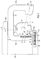
- Figure 1 shows diagrammatically in a side view a conventional panoramic radiographic apparatus of dental radiography with its patient positioning elements employed in conjunction with the present invention.
- Figure 2 shows the apparatus illustrated in Fig. 1 in a top view. Additionally shown in Fig. 2 are the essential system parameters related to the imaging geometry and the location of the temporo-mandibular joints to be imaged.
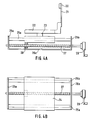
- Figure 3A shows a motor-actuated patient positioning mechanism in a side view.
- Figure 3B shows the same mechanism as Fig. 3A in a top view.
- Figure 4A shows a manually operated patient positioning mechanism in a similar view as that of Fig. 3A.
- Figure 4B shows the same mechanism as Fig. 4A in a top view.
- Figures 5A, 5B, 5C and 5D show the geometry of the dental arch and the temporo-mandibular joints to be imaged in the x-ray field for different imaging angles of the mandibular joints.
- Figure 6A shows in a graphic form the rotational speed profile of the x-ray beam as a function of time during the imaging of the temporo-mandibular joint according to the invention.
- Figure 6B shows similarly to Fig. 6A the film travel speed profile during the imaging of the temporo-mandibular joint according to the invention when the rotational speed profile is that illustrated in Fig. 6A.
- FIG. 7 shows the block diagram of the control system employed in the method and apparatus according to the invention.
- the principal elements of a conventional panoramic radiographic apparatus applied to narrow-beam tomography comprises a so-called C-arm that incorporates a horizontal part 11 plus vertical parts 11a and 11b at its ends between which the patient P to be radiographed is placed.
- One vertical part 11a of the C-arm supports an x-ray source 12, while the other vertical part 11b carries an x-ray film cassette 14.
- the cassette 14 contains a film F onto which the narrow-beam panoramic image of the patient's dental structure is exposed.
- the film cassette 14 with its contained film F is arranged to be transferrable by means of a conventional motor actuator designated by reference number 32 in Fig.
- the radiation is emitted from a focal point FC of the x-ray source 12 as a narrow beam X as illustrated in the horizontal section of Fig. 2.
- Fig. 2 the dental arch of the patient P is designated with reference L, the dental arch with reference T and the sections of the temporo-mandibular joints with references K R and K L and the patient's medial-sagittal plane with reference MS.
- the instantaneous imaging in the novel imaging mode according to the present invention takes place in mutually parallel planes (P1...P1,P2...P2) intersecting the mandibular joints K R and K L of the patient P as described by the basic formula of panoramic radiography given below:
- L1 distance from focal point FC to the film plane
- v1 velocity of image point on the image or film plane.
- the C-arm 11 has started its motion and reached a position in which the cassette 14 is in the position 141 and the focal point of the x-ray beam has reached the position FC1, from which an x-ray beam X1 is aimed to the center of the left mandibular joint K L , whereby said mandibular joint K L becomes sharply imaged in the plane P1...P1, whose distance is r from the virtual axis of rotation R0.
- the C-arm continues its motion in the direction of the arrow R via the position shown in dashed line to a position in which the focus of the x-ray source 12 is in the position FC2, whereby the x-ray beam is aligned to the right mandibular joint K R , whereby the right mandibular joint K R becomes sharply imaged in the plane P2...P2.
- the x-ray film cassette is in the position 142.
- Figures 3A, 3B and 4A, 4B illustrate the mechanisms by which the patient P can be placed in his/her medial-sagittal plane MS in the direction of narrow S shown in Fig. 1 to such a position in which both mandibular joints K R and K L can be imaged on a single film during a single exposure in preset imaging angles to be discussed later in conjunction with Figs. 5A...5D.
- the positioning mechanism of the patient P comprises at the upper end of an arm 21 a lip support 20 on which the upper lip of the patient P can rest so that the exposure can be performed both with an open and closed mouth of the patient P.
- the arm 21 is attached at its lower end to an L-arm 22, whose lower side is attached via a member 23 to a guided slide 24.
- Said slide is transferrable along horizontal guides 25a and 25b by means of a transfer screw 27.
- the transfer screw 27 is mounted in bearings between end members 26a and 26b of the transfer mechanism, said members also having the guides 25a and 25b attached to them.
- the glide block 24 has a nut element 28 attached to it, preferably a ball circulating nut running on the tread of the transfer screw 24. According to Figures 3A and 3B, the transfer screw is driven by a stepper motor 30 driven by circuit 33.
- the above-described patient positioning mechanisms are employed in both imaging modes of the panoramic x-ray apparatus, that is, in both the normal (first) imaging mode in which x-ray imaging is performed over the entire dental arch and the imaging mode (second) according to the invention in which imaging is performed at both temporo-mandibular joints K L and K R on a single film F from an angle which is adjustable to a preset value by means of the adjustment mechanism described above.
- Fig. 5A the temporo-mandibular joints K are imaged in the planes P1...P1 and P2...P2 from an angle of 95°.
- Figure 2 the patient P has been moved forward, that is, toward the film cassette 14 so that the mandibular joints K2 are imaged from an angle of 85°.
- FIGS 6A and 6B is shown the rotational speed v R of the C-arm corresponding to the angular velocity ⁇ and the film travel speed v1 indicated in the diagram of Fig. 2 as a function of time t.
- the rotation of the C-arm about a pivotal axis A-A is commenced from a home position by means of a motor 31 shown in Fig. 7 when the mandibular joints are imaged in the novel imaging mode according to the invention.
- the rotational speed of the C-arm as well as film travel speed v1 are first ramped in an essentially linear manner according to the diagram of Fig. 6.
- the area of the left mandibular joint K L is first imaged during the time interval T1 so that the C-arm is at time instant t1 in a position corresponding to the position FC1 of the x-ray source focal point indicated in Fig. 2.
- the rotational speed v R (having a maximum value of v R1 ) is reduced down to a minimum value v R2 and the film travel speed v1 is reduced by a relatively greater value, after which the imaging operation proceeds to the object area of the second mandibular joint K R , which is covered during the time interval T2.
- the C-arm is in the position indicated by dashed line in the diagram of Fig. 2, where the focal point of the x-ray source is indicated by FC2.
- both the rotational speed v R and the film travel speed v1 are brought down to zero in the manner shown in Figs. 6A and 6B, whereby the simultaneous imaging of both temporo-mandibular joints K L and K R on a single film F is completed.
- the speed profiles of the rotational speed v R and the film travel speed v1 described above in conjunction with the explanation of Figs. 6A and 6B are achieved by means of a control system illustrated in Figure 7, whereby said control system is also applicable during the normal panoramic imaging mode of the dental arch.
- the control system comprises a central unit 40 with a keyboard 41 and a display 42 attached to it. Connected to the central unit 40 is a memory 43 containing the speed profile tables of the motors 30,31,32.
- the central unit 40 is connected via a sequencing unit 44 of the mandibular joint imaging mode to driver circuits 33, 34 and 35 of the motors 30, 31 and 32.
- the apparatus is controlled from the keyboard 41 into the mandibular joint imaging mode, whereby the sequencing unit 44 of the mandibular imaging mode is activated.
- the imaging angle is entered, whereby its value can be vied according to Figs. 5A...5D in the range 65°...95°, for example.
- the display 42 indicates the imaging angle and the central unit 40 fetches the speed profile tables corresponding to the selected imaging angle of the mandibular imaging mode from the memory 43.
- the central unit 40 controls via the sequencing unit 44 of the mandibular imaging mode first the motor 30 so that patient positioning mechanism 20,21 is transferred to a position corresponding to the imaging mode entered from the keyboard 41.
- the central unit 40 controls with the help of the speed profile tables fetched from the memory 43 the motors 31 and 32 so that the speed profiles v R (t) and v1(t) shown in Figs. 6A and 6B are implemented.
Landscapes
- Health & Medical Sciences (AREA)
- Life Sciences & Earth Sciences (AREA)
- Engineering & Computer Science (AREA)
- Medical Informatics (AREA)
- Radiology & Medical Imaging (AREA)
- Biomedical Technology (AREA)
- Biophysics (AREA)
- High Energy & Nuclear Physics (AREA)
- Veterinary Medicine (AREA)
- Nuclear Medicine, Radiotherapy & Molecular Imaging (AREA)
- Optics & Photonics (AREA)
- Pathology (AREA)
- Public Health (AREA)
- Physics & Mathematics (AREA)
- Heart & Thoracic Surgery (AREA)
- Molecular Biology (AREA)
- Surgery (AREA)
- Animal Behavior & Ethology (AREA)
- General Health & Medical Sciences (AREA)
- Pulmonology (AREA)
- Theoretical Computer Science (AREA)
- Dentistry (AREA)
- Oral & Maxillofacial Surgery (AREA)
- Apparatus For Radiation Diagnosis (AREA)
Abstract
Description
- The invention relates to a method of narrow-beam panoramic radiography, said method utilizing an x-ray source whose narrow x-ray beam is aimed to pass through the object area to be radiographed onto a movable x-ray film, in which method the object area to radiographed in the patient is kept stationary in a certain preset position, while the x-ray source is rotated about a virtual, preferably vertical axis of rotation and a film cassette is simultaneously moved, and in which method according to its first operating mode the patient is supported by patient positioning means for exposing panoramic radiographic images of the dental arch so that the sharply imaging plane is located between the virtual axis of rotation of the x-ray beam and the film plane, and in which method in addition to above-described first operating mode the panoramic x-ray apparatus is set to a specific exposure mode for imaging the dental arch and the patient is positioned in the panoramic x-ray apparatus with the help of above-mentioned patient positioning means.
- Furthermore, the invention concerns a panoramic tomographic apparatus for dental radiography, said apparatus comprising a body frame part to which is mounted another frame part, pivotal in bearings about a vertical axis, whose one end is carrying an x-ray tube and the other end carrying a film cassette, capable of housing an x-ray film, and the space between said x-ray tube and said film cassette being able to accommodate the object area to be radiographed in the patient, and said apparatus further comprising actuating means, capable of rotating said pivotally mounted frame part in the horizontal plane and transferring said film cassette simultaneously for exposing a panoramic radiographic image, and said apparatus further comprising patient positioning means which are transferrable manually or by a motor in the forward-backward direction for positioning the patient in such a position that in the specific mandibular joint imaging mode permits the imaging of the mandibular joint.
- Most panoramic radiographic equipment intended for dental radiography, are by their function and construction so designed that their x-ray source is rotated about the patient's skull, whereby the dental arch can be imaged onto a movable film in a planar development of the dental arch. In order to achieve a sharp image of the object area onto the film with a simultaneous desired "blurring" of the structures situated along the beam axis in the front or rear of the object area, the film travel speed orthogonally to the exposing beam must be equal to the sweep velocity of the beam at the imaged object area multiplied by the magnification. The magnification is set by the ratio of distance from the focal point to the film plane to the distance from the focal point to the object area being imaged. The thickness of sharply imaging layer'is linearly proportional to'the distance of the virtual axis of rotation from the film plane and inversely proportional to the magnification and the width of the x-ray beam. Only the mutual locations of the focal point, imaged object area and film plane are relevant to the radiographic process. By contrast, the location of the virtual axis of rotation is solely related to the sweep velocity.
- As an example of panoramic tomography apparatuses known in the art for dental radiography, reference is made to the FI patent 73091 (US patent 4,741,007, correspondingly) and FI patent 853524 (US patent 4,783,793, correspondingly), both filed by the applicant of the present patent.
- Panoramic tomography apparatuses intended for dental radiography have mainly been used for radiographing the dental arch and the temporo-mandibular joints, or their condyles. It is a principal object of the present invention to further develop the apparatuses disclosed in the above-mentioned patents and the application filed by the applicant as well as other similar panoramic tomography apparatuses so that mandibular joint imaging projections of still greater versatility and higher diagnostic value become possible by means of simple accessories and/or arrangements without causing an essential increase in the price of the basic panoramic x-ray apparatus.
- X-ray images taken from the temporo-mandibular joints are diagnostically a valuable source of information in a multitude of states of illness and pain. Imaging of the condyles is necessary in the diagnostics of a variety of problems encountered in oral surgery, biting disorders, straightening of teeth and malfunction of the temporo-mandibular joint. When exposing the temporo-mandibular joint in radiographic imaging, it is of extreme importance that the sharply imaging plane is both correctly positioned and correctly aligned so that the head of the condylar process and the mandibular fossa of the joint as well as the soft tissue between them can be imaged sharply and from a correct direction in order to reveal, for example, the degree of wear in the joint and its positional disorders.
- The diagnostic value of radiographic images taken from temporo-mandibular area by means of conventional panoramic x-ray apparatuses is degraded through a non-optimal orientation of the x-ray beam during its sweep over the temporo-mandibular joint. This is related to the fact that, in order to attain a nondistorted image over the dental arch area, such an imaging geometry of panoramic x-ray apparatuses is preferred in which the x-ray beam passes through the mandible as perpendicularly as possible at the dental arch. In conventional apparatuses there is a corollary result that the requirement of perpendicularity cannot be fulfilled at the temporo-mandibular joint, or alternatively, its fulfillment would compel the use of such an imaging geometry in which the motion of the virtual axis of rotation at the condylar area is such in that the tomographic imaging effect is lost. Here, the situation approaches that of conventional radiography, which means that the whole of the patient's anatomy incorporated at the swept area is imaged on the film, whereby both temporo-mandibular joints, for example, become superimposed in the image.
- It is a particular object of the invention to achieve such a narrow-beam tomographic method and such an apparatus which is based on a standard panoramic x-ray apparatus conventionally employed for imaging of dental structures, said apparatus being complemented in a novel and advantageous way with a new imaging mode in which the temporo-mandibular joints and structures adjacent thereof can be imaged with higher image quality and improved diagnostic value. Such a facility provides an essential improvement in the utility of conventional panoramic tomography apparatuses and makes investments in apparatuses more profitable and more justifiable for smaller health care units than before by virtue of the widened applicability of the apparatus.
- It is a further particular object of the invention to achieve such a method and apparatus, which permits, using standard panoramic x-ray apparatuses conventionally employed for imaging of dental structures, the imaging of both temporo-mandibular joints during a single exposure on a single film using mutually parallel imaging planes of the joints so that the imaging angle can be set within a certain sufficient range of angles employing simple implements to adjust the imaging angle optimal with respect to the imaged object area and the goal of imaging.
- To achieve the goals described above and discussed later, the method according to the invention is principally characterized in that the speeds of the rotating motor and the film transfer motor in a frame part supporting the x-ray source and the film cassette are varied, or alternatively, the profiles of said speeds are set so that the shape of the sharply-imaging layers is appropriately contoured so as to make the mandibular joints coincide with the imaged layer irrespective of the position of the patient in the medial-sagittal plane.
- Furthermore, the apparatus according to the invention is principally characterized in that said apparatus incorporates such motion control arrangements by which the arm connecting the x-ray source and the film cassette is pivotally rotatable and the film cassette is simultaneously transferrable using such speed profiles that both mandibular joints can be imaged on a single film in planes which are essentially parallel with the medial-sagittal plane of the patient.
- The imaging mode of the mandibular joint condyles according to the invention can be adapted to conventional panoramic x-ray apparatuses by programming the logic control systems of motor drives to perform according to the above-mentioned imaging mode of mandibular joint condyles. The imaging mode of the mandibular joint condyles according to the invention requires no particular patient positioning and supporting arrangements, but rather the imaging angle of the mandibular joint can be varied in the horizontal plane by moving the patient in his medial-sagittal plane. The necessary adjustment members of patient positioning are generally already available in conventional panoramic x-ray apparatuses of standard equipping for optimal placement of the patient in a conventional panoramic x-ray exposure of the dental arches.
- The method and apparatus according to the invention achieves a narrow-beam tomographic image of both temporo-mandibular joints on a single film during a single exposure from such an imaging angle that can be set through rapid and simple procedures optimal with respect to the goal of imaging.
- The invention is next examined in greater detail by making reference to the figures of the attached drawing which illustrate diagrammatically a few exemplifying embodiments of the present invention, whereby the illustrating details must not be construed to limit the applications of the invention.
- Figure 1 shows diagrammatically in a side view a conventional panoramic radiographic apparatus of dental radiography with its patient positioning elements employed in conjunction with the present invention.
- Figure 2 shows the apparatus illustrated in Fig. 1 in a top view. Additionally shown in Fig. 2 are the essential system parameters related to the imaging geometry and the location of the temporo-mandibular joints to be imaged.
- Figure 3A shows a motor-actuated patient positioning mechanism in a side view.
- Figure 3B shows the same mechanism as Fig. 3A in a top view.
- Figure 4A shows a manually operated patient positioning mechanism in a similar view as that of Fig. 3A.
- Figure 4B shows the same mechanism as Fig. 4A in a top view.
- Figures 5A, 5B, 5C and 5D show the geometry of the dental arch and the temporo-mandibular joints to be imaged in the x-ray field for different imaging angles of the mandibular joints.
- Figure 6A shows in a graphic form the rotational speed profile of the x-ray beam as a function of time during the imaging of the temporo-mandibular joint according to the invention.
- Figure 6B shows similarly to Fig. 6A the film travel speed profile during the imaging of the temporo-mandibular joint according to the invention when the rotational speed profile is that illustrated in Fig. 6A.
- Figure 7 shows the block diagram of the control system employed in the method and apparatus according to the invention.
- According to Figs. 1 and 2, the principal elements of a conventional panoramic radiographic apparatus applied to narrow-beam tomography comprises a so-called C-arm that incorporates a
horizontal part 11 plusvertical parts vertical part 11a of the C-arm supports anx-ray source 12, while the othervertical part 11b carries anx-ray film cassette 14. Thecassette 14 contains a film F onto which the narrow-beam panoramic image of the patient's dental structure is exposed. Thefilm cassette 14 with its contained film F is arranged to be transferrable by means of a conventional motor actuator designated by reference number 32 in Fig. 7 simultaneously with the rotational motion of the C-arm about a nonstationary virtual vertical axis A-A at an angular velocity ω by means of a motor 31 shown in Fig. 7. During the exposure, the radiation is emitted from a focal point FC of thex-ray source 12 as a narrow beam X as illustrated in the horizontal section of Fig. 2. - In Fig. 2 the dental arch of the patient P is designated with reference L, the dental arch with reference T and the sections of the temporo-mandibular joints with references KR and KL and the patient's medial-sagittal plane with reference MS.
- According to Fig. 2, the instantaneous imaging in the novel imaging mode according to the present invention takes place in mutually parallel planes (P₁...P₁,P₂...P₂) intersecting the mandibular joints KR and KL of the patient P as described by the basic formula of panoramic radiography given below:
v₁/v₀ = L₁/L₀
v₀ = ω·r, where
L₀ = distance from focal point FC to the instantaneously imaged point of the layer being imaged
L₁ = distance from focal point FC to the film plane
ω = angular velocity of rotational motion about the virtual axis of rotation
r = distance of imaged point from the virtual axis of rotation R₀ of the rotational motion
v₁ = velocity of image point on the image or film plane. - During the imaging of the mandibular joints K in the imaging mode of the mandibular joint condyles according to the invention as illustrated in Fig. 2, the C-
arm 11 has started its motion and reached a position in which thecassette 14 is in the position 14₁ and the focal point of the x-ray beam has reached the position FC₁, from which an x-ray beam X₁ is aimed to the center of the left mandibular joint KL, whereby said mandibular joint KL becomes sharply imaged in the plane P₁...P₁, whose distance is r from the virtual axis of rotation R₀. Next, the C-arm continues its motion in the direction of the arrow R via the position shown in dashed line to a position in which the focus of thex-ray source 12 is in the position FC₂, whereby the x-ray beam is aligned to the right mandibular joint KR, whereby the right mandibular joint KR becomes sharply imaged in the plane P₂...P₂. Then, the x-ray film cassette is in theposition 14₂. - In the embodiment of the present invention, the layers imaged in the planes P₁...P₁,P₂...P₂ passing through the mandibular joints KL and KR are aligned planar and mutually parallel by virtue of an appropriate program-controlled realization of the speeds vR and v₁ of the C-arm rotating motor 31 and the film transfer motor 32 in the manner to be described later in detail in conjunction with the description of Figs. 6A, 6B and 7 so as to keep the above-described imaging condition v₁/v₀ = L₁/L₀ valid.
- Figures 3A, 3B and 4A, 4B illustrate the mechanisms by which the patient P can be placed in his/her medial-sagittal plane MS in the direction of narrow S shown in Fig. 1 to such a position in which both mandibular joints KR and KL can be imaged on a single film during a single exposure in preset imaging angles to be discussed later in conjunction with Figs. 5A...5D. The positioning mechanism of the patient P comprises at the upper end of an arm 21 a
lip support 20 on which the upper lip of the patient P can rest so that the exposure can be performed both with an open and closed mouth of the patient P. Thearm 21 is attached at its lower end to an L-arm 22, whose lower side is attached via amember 23 to a guidedslide 24. Said slide is transferrable alonghorizontal guides transfer screw 27. Thetransfer screw 27 is mounted in bearings betweenend members guides glide block 24 has anut element 28 attached to it, preferably a ball circulating nut running on the tread of thetransfer screw 24. According to Figures 3A and 3B, the transfer screw is driven by astepper motor 30 driven bycircuit 33. - The above-described patient positioning mechanisms are employed in both imaging modes of the panoramic x-ray apparatus, that is, in both the normal (first) imaging mode in which x-ray imaging is performed over the entire dental arch and the imaging mode (second) according to the invention in which imaging is performed at both temporo-mandibular joints KL and KR on a single film F from an angle which is adjustable to a preset value by means of the adjustment mechanism described above. The location of the dental arch and the mandibular joints K to be imaged is shown in Figures 5A, 5B, 5C and 5D in an x-ray field (angle scales 0°...100°, angle 0° = medial-sagittal plane MS of the patient P) when the patient is set to different positions by means of mechanisms shown in Figs. 3A, 3B or 4A, 4B. According to Fig. 5A, the temporo-mandibular joints K are imaged in the planes P₁...P₁ and P₂...P₂ from an angle of 95°. In Figure 2 the patient P has been moved forward, that is, toward the
film cassette 14 so that the mandibular joints K₂ are imaged from an angle of 85°. In Figure 5C the patient has further been moved forward so that the mandibular joints K₃ are imaged from an angle of 85° and the forward transfer identified in the diagram relative to the initial position indicated in Fig. 5A are in this example maximally = S₀, whereby the mandibular joints K₄ are imaged in an angle of 65°. In typical applications the range of 55°...95° is sufficient and possible so that the transfer distance S₀ of the patient still remains within such boundaries which avoid the collision of thefilm cassette 14 with the patient P. - In Figures 6A and 6B is shown the rotational speed vR of the C-arm corresponding to the angular velocity ω and the film travel speed v₁ indicated in the diagram of Fig. 2 as a function of time t. The rotation of the C-arm about a pivotal axis A-A is commenced from a home position by means of a motor 31 shown in Fig. 7 when the mandibular joints are imaged in the novel imaging mode according to the invention. Here, the rotational speed of the C-arm as well as film travel speed v₁ are first ramped in an essentially linear manner according to the diagram of Fig. 6. According to Figures 6A and 6B, the area of the left mandibular joint KL, for example, is first imaged during the time interval T₁ so that the C-arm is at time instant t₁ in a position corresponding to the position FC₁ of the x-ray source focal point indicated in Fig. 2. During the imaging of the first mandibular joint KL the film travel speed is kept constant = v₁₀. Then, after the imaging of the first mandibular joint KL is ready, the rotational speed vR (having a maximum value of vR1) is reduced down to a minimum value vR2 and the film travel speed v₁ is reduced by a relatively greater value, after which the imaging operation proceeds to the object area of the second mandibular joint KR, which is covered during the time interval T₂. At time instant t₂ the C-arm is in the position indicated by dashed line in the diagram of Fig. 2, where the focal point of the x-ray source is indicated by FC₂. When also the imaging of the second mandibular joint KR is completed, both the rotational speed vR and the film travel speed v₁ are brought down to zero in the manner shown in Figs. 6A and 6B, whereby the simultaneous imaging of both temporo-mandibular joints KL and KR on a single film F is completed.
- The speed profiles of the rotational speed vR and the film travel speed v₁ described above in conjunction with the explanation of Figs. 6A and 6B are achieved by means of a control system illustrated in Figure 7, whereby said control system is also applicable during the normal panoramic imaging mode of the dental arch. The control system comprises a
central unit 40 with akeyboard 41 and adisplay 42 attached to it. Connected to thecentral unit 40 is amemory 43 containing the speed profile tables of themotors 30,31,32. When operating in the novel imaging mode of the mandibular condyles according to the invention, thecentral unit 40 is connected via asequencing unit 44 of the mandibular joint imaging mode todriver circuits motors 30, 31 and 32. At the start of mandibular joint imaging, the apparatus is controlled from thekeyboard 41 into the mandibular joint imaging mode, whereby thesequencing unit 44 of the mandibular imaging mode is activated. Using thekeyboard 41, the imaging angle is entered, whereby its value can be vied according to Figs. 5A...5D in the range 65°...95°, for example. Thedisplay 42 indicates the imaging angle and thecentral unit 40 fetches the speed profile tables corresponding to the selected imaging angle of the mandibular imaging mode from thememory 43. Thecentral unit 40 controls via thesequencing unit 44 of the mandibular imaging mode first themotor 30 so thatpatient positioning mechanism keyboard 41. When the mandibular imaging operation is started after this under control from the keyboard, thecentral unit 40 controls with the help of the speed profile tables fetched from thememory 43 the motors 31 and 32 so that the speed profiles vR(t) and v₁(t) shown in Figs. 6A and 6B are implemented. - Whereas only such an embodiment of the invention is described above in which the rotational speed vR and the film travel speed v₁ are varied under program control in both the panoramic imaging mode and the novel mandibular joint imaging mode, the invention also concerns such applications in which said control is implemented by mechanical means in either or both imaging modes, whereby such a rotating mechanism of the C-
arm 11 is possible, for example, as is disclosed in the FI patent 73091 (US patent 4,741,007, correspondingly). - The claims of the patent application are presented in the following, whereby the different details of the invention may be varied and deviated within the scope of the claims which define the invention from those of the exemplifying embodiments.
Claims (9)
- A method of narrow-beam tomography utilizing an x-ray source (12) whose narrow x-ray beam (X) is aimed to pass through the object area to be radiographed onto a movable x-ray film (F), in which method the object area to be radiographed in the patient (P) is kept stationary in a certain preset position, while the x-ray source (12) is rotated about a vitual, preferably vertical axis of rotation (R₀) and a film cassette (14) is simultaneously moved, and in which method according to its first operating mode the patient (P) is supported by patient positioning means (20...30) for exposing panoramic radiographic images of the dental arch (L) so that the sharply imaging plane is located between the vitual axis of rotation of the x-ray beam and the film plane, and in which method in addition to above-described first operating mode the panoramic x-ray apparatus is set to a specific exposure mode for imaging the dental arch and the patient is positioned in the panoramic x-ray apparatus with the help of above-mentioned patient positioning means (20...30), characterized in that the speeds (vR,v₁) of the rotating motor (31) and the film transfer motor (32) in a frame part (15) supporting the x-ray source (12) and the film cassette (14) are varied, or alternatively, the profiles of said speeds are set so that the shape of the sharply-imaging layers (P₁-P₁,P₂-P₂) is appropriately contoured so as to make the mandibular joints (K) to coincide with the imaged layer irrespective of the position of the patient (P) in the medial-sagittal plane (MS).
- A method as defined in claim 1, characterized in that the sharply imaging layer in the mandibular joint imaging mode is set to coincide with vertically aligned planes (P₁...P₁,P₂...P₂) which are parallel to the medial-sagittal plane (MS) of the patient (P) and pass through the condyles of the mandibular joints.
- A method as defiined in claim 1 or 2, characterized in that, prior to the commencement of the mandibular joint imaging mode, the positioning means (20,21,22) of the patient (P) are transferred in the forward-backward direction (S), whereby said transfer selects the imaging angle from which the x-ray beam is aimed through the condyles (K) of the mandibular joints.
- A method as defined in any of foregoing claim 1...3, characterized in that according to said method the positioning means (20...24) of the patient (P) are transferred by a motor (30), whose function is controlled via the driver circuits (33) of a central unit (40) of the control system of the panoramic tomography apparatus and the motor (30).
- A method as defined in anyof foregoing claims 1...4, characterized in that according to said method the speed profiles of the rotating motor (31) and the film transfer motor (35) are controlled using speed profile tables stored in a memory (43) of the central unit (40) of the control system of the apparatus.
- A panoramic tomographic apparatus for dental radiography, said apparatus comprising a body part (13b) to which is mounted another frame part (11, 11a, 11b), pivotal in bearings about a vertical axis (A-A), whose one end is carrying an x-ray tube (12) and the other end carrying a film cassette (14), capable of housing an x-ray film (F), and the space between said x-ray tube (12) and said film cassette (14) being able to accommodate the object area to be radiographed in the patient (P), and said apparatus further comprising actuating means, capable of rotating said pivotally mounted frame part (11, 11a, 11b) in the horizontal plane and transferring said film cassette (14) simultaneously for exposing a panoramic radiographic image, and said apparatus further comprising patient positioning means (20,21) which are transferrable manually or by a motor (30) in the forward-backward direction for positioning the patient (P) in such a position that in the specific mandibular joint imaging mode permits the imaging of the mandibular joint, characterized in that said apparatus incorporates such motion control arrangements by which the arm (11, 11a, 11b) connecting the x-ray source (12) and the film cassette (14) is pivotally rotatable and the film cassette (14) is simultaneously transferrable using such speed profiles (vR(t) and v₁(t)) that both mandibular joints (KR,KL) can be imaged on a single film (F) in planes which are essentially parallel with the medial-sagittal plane (MS) of the patient (P).
- An apparatus as defined in claim 6, characterized in that patient positioning means (20...29) are arranged to be adjustable either manually (Figs. 4A,4B) or by means of a motor (30) driven by a central unit (40) of the apparatus so that the angle to the medial-sagittal plane (MS) of the patient at which the x-ray beam (X) intersects the condyles of the mandibular joints is selectable in the range of approx. 55°...95°.
- An apparatus as defined in claim 6, characterized in that said apparatus incorporates a transfer screw (27) and a nut or similar element driven by the motor (30), capable of transferring the patient positioning means (20,21) in the forward-backward direction (S), whereby said motor (30) is connected via its driver circuit (33) controllable by the central unit (40) of the panoramic x-ray apparatus.
- An apparatus as defined in claim 6 or 8, characterized in that said apparatus comprises such a control unit which incorporates a central unit (40) with an attached keyboard (41) and a display (42), and that said central unit (40) is adapted to control the speeds (vR,v₁) of the rotating motor (31) and the film transfer motor (32) in both a conventional panoramic imaging mode occurring along a contour conforming to the dental arch and a mandibular joint imaging mode, and that said central unit (40) is connectable to a memory unit (43) that contains speed profile tables of the different motors (30,31,32) of the apparatus for both said imaging modes.
Applications Claiming Priority (2)
| Application Number | Priority Date | Filing Date | Title |
|---|---|---|---|
| FI912180 | 1991-05-06 | ||
| FI912180A FI92973C (en) | 1991-05-06 | 1991-05-06 | Procedure and apparatus for panoramic X-ray photography |
Publications (2)
| Publication Number | Publication Date |
|---|---|
| EP0512964A1 true EP0512964A1 (en) | 1992-11-11 |
| EP0512964B1 EP0512964B1 (en) | 1996-11-20 |
Family
ID=8532450
Family Applications (1)
| Application Number | Title | Priority Date | Filing Date |
|---|---|---|---|
| EP92850095A Expired - Lifetime EP0512964B1 (en) | 1991-05-06 | 1992-04-27 | Method and apparatus for panoramic radiography |
Country Status (5)
| Country | Link |
|---|---|
| US (1) | US5267293A (en) |
| EP (1) | EP0512964B1 (en) |
| JP (1) | JPH0824677B2 (en) |
| DE (1) | DE69215267T2 (en) |
| FI (1) | FI92973C (en) |
Cited By (3)
| Publication number | Priority date | Publication date | Assignee | Title |
|---|---|---|---|---|
| US5444754A (en) * | 1993-10-13 | 1995-08-22 | Instrumentarium Corp. | Method for localizing cross-sectional dental X-ray images |
| US5732119A (en) * | 1995-05-12 | 1998-03-24 | Instrumentarium Corporation | Method for the automatic adjustment of exposure parameters in an imaging apparatus operating on linear tomographic principles |
| CN104997530A (en) * | 2014-04-17 | 2015-10-28 | 塞弗拉合作社 | Craniostat for acquiring extraoral dental radiographies |
Families Citing this family (18)
| Publication number | Priority date | Publication date | Assignee | Title |
|---|---|---|---|---|
| FI98488C (en) * | 1993-01-08 | 1997-07-10 | Orion Yhtymae Oy | A method for realizing standard magnification in panoramic X-ray imaging |
| JP2000197621A (en) * | 1999-01-06 | 2000-07-18 | Toshiba Corp | Medical picture photographing device |
| US8821158B1 (en) * | 1999-10-14 | 2014-09-02 | Geodigm Corporation | Method and apparatus for matching digital three-dimensional dental models with digital three-dimensional cranio-facial CAT scan records |
| US6381301B1 (en) | 1999-12-01 | 2002-04-30 | Ronald E. Massie | Dental and orthopedic densitometry modeling system and method |
| US7347686B2 (en) | 2002-01-22 | 2008-03-25 | Geodigm Corporation | Method and apparatus using a scanned image for marking bracket locations |
| US7387511B2 (en) | 2002-01-22 | 2008-06-17 | Geodigm Corporation | Method and apparatus using a scanned image for automatically placing bracket in pre-determined locations |
| US7716024B2 (en) | 2002-04-29 | 2010-05-11 | Geodigm Corporation | Method and apparatus for electronically generating a color dental occlusion map within electronic model images |
| US20030220778A1 (en) * | 2002-04-29 | 2003-11-27 | Hultgren Bruce Willard | Method and apparatus for electronically simulating jaw function within electronic model images |
| CA2393101A1 (en) * | 2002-07-11 | 2004-01-11 | Martin Cyr | Apparatus, system and method of calibrating medical imaging systems |
| US7824346B2 (en) | 2004-03-11 | 2010-11-02 | Geodigm Corporation | Determining condyle displacement utilizing electronic models of dental impressions having a common coordinate system |
| US7702492B2 (en) | 2004-03-11 | 2010-04-20 | Geodigm Corporation | System and method for generating an electronic model for a dental impression having a common coordinate system |
| JP4514550B2 (en) * | 2004-08-10 | 2010-07-28 | 株式会社モリタ製作所 | Operation device and photographing device |
| US7471761B2 (en) * | 2005-09-15 | 2008-12-30 | Schick Technologies, Inc. | System and method for computing oral bone mineral density with a panoramic x-ray system |
| US7690917B2 (en) | 2006-08-17 | 2010-04-06 | Geodigm Corporation | Bracket alignment device |
| KR101393196B1 (en) | 2007-05-09 | 2014-05-08 | 아이로보트 코퍼레이션 | Compact autonomous coverage robot |
| EP2280651A2 (en) * | 2008-05-16 | 2011-02-09 | Geodigm Corporation | Method and apparatus for combining 3d dental scans with other 3d data sets |
| KR101192461B1 (en) * | 2011-02-25 | 2012-10-17 | 이화여자대학교 산학협력단 | X-ray panorama imaging apparatus in oral cavity |
| US10853939B2 (en) * | 2015-02-26 | 2020-12-01 | Maryam Afifi | System and method for diagnosis and assessment of disc derangement disorders |
Citations (3)
| Publication number | Priority date | Publication date | Assignee | Title |
|---|---|---|---|---|
| EP0062962A1 (en) * | 1981-02-20 | 1982-10-20 | Erkki Tammisalo | A method to be used in panoramic X-ray photography and an apparatus for carrying out the method |
| EP0215757A2 (en) * | 1985-09-13 | 1987-03-25 | Planmeca Oy | Control system of an X-ray apparatus for panoramic tomography |
| DE3937077A1 (en) * | 1988-11-08 | 1990-05-10 | Morita Mfg | MEDICAL OR DENTAL PANORAMIC ORGANIZATION |
Family Cites Families (9)
| Publication number | Priority date | Publication date | Assignee | Title |
|---|---|---|---|---|
| JPS54113292A (en) * | 1978-02-23 | 1979-09-04 | Morita Mfg | Dental panorama xxray camera for taking jaw joint standard |
| JPS5714325A (en) * | 1980-06-30 | 1982-01-25 | Asahi Roentgen Ind | X-ray curved surface tomogram apparatus |
| FI840044A (en) * | 1984-01-06 | 1985-07-07 | Instrumentarium Oy | PATIENTENS STOEDSYSTEM VID EN SMALSTRAOLKNIPPETOMOGRAFIAVBILDNINGSANORDNING. |
| JPS60150733A (en) * | 1984-01-20 | 1985-08-08 | 株式会社モリタ製作所 | Dental total jaw x-ray photographing apparatus |
| DE3675525D1 (en) * | 1985-12-20 | 1990-12-13 | Siemens Ag | DENTAL X-RAY DIAGNOSTIC DEVICE FOR CREATING PANORAMIC LAYING FROM A PATIENT'S JAW. |
| FI79459C (en) * | 1986-02-04 | 1990-01-10 | Orion Yhtymae Oy | Procedure and facility for X-ray photography of the area of the teeth, jaws and skull |
| EP0262500B1 (en) * | 1986-09-26 | 1993-11-18 | Siemens Aktiengesellschaft | Diagnostic dental X-ray apparatus for producing panoramic exposures of cranial strata |
| EP0340349B1 (en) * | 1988-05-06 | 1998-10-21 | Dentsply Research & Development Corp. | Dental X-ray apparatus for panoramic tomography |
| JPH01293845A (en) * | 1988-05-24 | 1989-11-27 | Asahi Roentgen Kogyo Kk | Panoramic x-ray imaging apparatus |
-
1991
- 1991-05-06 FI FI912180A patent/FI92973C/en active IP Right Grant
-
1992
- 1992-04-27 DE DE69215267T patent/DE69215267T2/en not_active Expired - Fee Related
- 1992-04-27 EP EP92850095A patent/EP0512964B1/en not_active Expired - Lifetime
- 1992-05-04 US US07/878,159 patent/US5267293A/en not_active Expired - Lifetime
- 1992-05-06 JP JP4113701A patent/JPH0824677B2/en not_active Expired - Lifetime
Patent Citations (3)
| Publication number | Priority date | Publication date | Assignee | Title |
|---|---|---|---|---|
| EP0062962A1 (en) * | 1981-02-20 | 1982-10-20 | Erkki Tammisalo | A method to be used in panoramic X-ray photography and an apparatus for carrying out the method |
| EP0215757A2 (en) * | 1985-09-13 | 1987-03-25 | Planmeca Oy | Control system of an X-ray apparatus for panoramic tomography |
| DE3937077A1 (en) * | 1988-11-08 | 1990-05-10 | Morita Mfg | MEDICAL OR DENTAL PANORAMIC ORGANIZATION |
Cited By (3)
| Publication number | Priority date | Publication date | Assignee | Title |
|---|---|---|---|---|
| US5444754A (en) * | 1993-10-13 | 1995-08-22 | Instrumentarium Corp. | Method for localizing cross-sectional dental X-ray images |
| US5732119A (en) * | 1995-05-12 | 1998-03-24 | Instrumentarium Corporation | Method for the automatic adjustment of exposure parameters in an imaging apparatus operating on linear tomographic principles |
| CN104997530A (en) * | 2014-04-17 | 2015-10-28 | 塞弗拉合作社 | Craniostat for acquiring extraoral dental radiographies |
Also Published As
| Publication number | Publication date |
|---|---|
| FI912180A0 (en) | 1991-05-06 |
| FI92973B (en) | 1994-10-31 |
| FI92973C (en) | 1995-02-10 |
| JPH05154143A (en) | 1993-06-22 |
| DE69215267D1 (en) | 1997-01-02 |
| JPH0824677B2 (en) | 1996-03-13 |
| US5267293A (en) | 1993-11-30 |
| EP0512964B1 (en) | 1996-11-20 |
| FI912180A (en) | 1992-11-07 |
| DE69215267T2 (en) | 1997-03-13 |
Similar Documents
| Publication | Publication Date | Title |
|---|---|---|
| EP0512964B1 (en) | Method and apparatus for panoramic radiography | |
| US6466641B1 (en) | Cranial radiography apparatus | |
| US7837385B2 (en) | Method for recording X-ray images by means of a robotically controlled C-arm system and recording device for recording X-ray images | |
| US7424091B2 (en) | Combined panoramic, CT (computed tomography) and cephalometric photographing apparatus | |
| US6493415B1 (en) | X-ray computed tomography method and apparatus | |
| EP0340349B1 (en) | Dental X-ray apparatus for panoramic tomography | |
| US4653083A (en) | Spherical X-ray angulation and patient tilting system | |
| US20010036246A1 (en) | X-ray device and medical workplace for diagnostics and surgical interventions in the head and/or jaw of a patient | |
| US20090168966A1 (en) | Medical Digital X-Ray Imaging Apparatus and Medical Digital X-Ray Sensor | |
| US6439769B1 (en) | Automated receptor tracking to diagnostic source assembly | |
| US4847881A (en) | Dental x-ray diagnostics installation for producing panorama tomograms of the jaw of a patient | |
| US5224140A (en) | Method and apparatus for panoramic radiography | |
| JP2005013768A (en) | X-ray ct apparatus | |
| US3927326A (en) | X-ray examining apparatus | |
| JP4458773B2 (en) | Image shooting device | |
| JPS59151945A (en) | X-ray table apparatus for tomography having false fulcrum point arm pivot shaft | |
| JPH11197147A (en) | Device for radiographic examination | |
| JPH10314162A (en) | Radiation tomography and its device | |
| US7614786B2 (en) | Positioning device for an X-ray detector | |
| JP3447362B2 (en) | Radiation treatment planning device | |
| WO1996006561A1 (en) | Self-contained apparatus for skeletal radiographic tomography | |
| JPS6146141B2 (en) | ||
| US5148454A (en) | Apparatus for conducting cranial X-ray tomography and radiography | |
| JPH0411691Y2 (en) | ||
| US20080031401A1 (en) | Method and apparatus for displaying a region to be examined of an examination object |
Legal Events
| Date | Code | Title | Description |
|---|---|---|---|
| PUAI | Public reference made under article 153(3) epc to a published international application that has entered the european phase |
Free format text: ORIGINAL CODE: 0009012 |
|
| AK | Designated contracting states |
Kind code of ref document: A1 Designated state(s): DE ES FR GB IT MC NL SE |
|
| 17P | Request for examination filed |
Effective date: 19930121 |
|
| 17Q | First examination report despatched |
Effective date: 19941007 |
|
| GRAG | Despatch of communication of intention to grant |
Free format text: ORIGINAL CODE: EPIDOS AGRA |
|
| GRAH | Despatch of communication of intention to grant a patent |
Free format text: ORIGINAL CODE: EPIDOS IGRA |
|
| GRAH | Despatch of communication of intention to grant a patent |
Free format text: ORIGINAL CODE: EPIDOS IGRA |
|
| GRAA | (expected) grant |
Free format text: ORIGINAL CODE: 0009210 |
|
| AK | Designated contracting states |
Kind code of ref document: B1 Designated state(s): DE ES FR GB IT MC NL SE |
|
| PG25 | Lapsed in a contracting state [announced via postgrant information from national office to epo] |
Ref country code: NL Free format text: LAPSE BECAUSE OF FAILURE TO SUBMIT A TRANSLATION OF THE DESCRIPTION OR TO PAY THE FEE WITHIN THE PRESCRIBED TIME-LIMIT Effective date: 19961120 Ref country code: ES Free format text: THE PATENT HAS BEEN ANNULLED BY A DECISION OF A NATIONAL AUTHORITY Effective date: 19961120 |
|
| REF | Corresponds to: |
Ref document number: 69215267 Country of ref document: DE Date of ref document: 19970102 |
|
| ET | Fr: translation filed | ||
| ITF | It: translation for a ep patent filed |
Owner name: STUDIO CONS. BREVETTUALE S.R.L. |
|
| PG25 | Lapsed in a contracting state [announced via postgrant information from national office to epo] |
Ref country code: SE Effective date: 19970220 |
|
| PG25 | Lapsed in a contracting state [announced via postgrant information from national office to epo] |
Ref country code: GB Effective date: 19970427 |
|
| NLV1 | Nl: lapsed or annulled due to failure to fulfill the requirements of art. 29p and 29m of the patents act | ||
| PLBE | No opposition filed within time limit |
Free format text: ORIGINAL CODE: 0009261 |
|
| STAA | Information on the status of an ep patent application or granted ep patent |
Free format text: STATUS: NO OPPOSITION FILED WITHIN TIME LIMIT |
|
| PG25 | Lapsed in a contracting state [announced via postgrant information from national office to epo] |
Ref country code: MC Effective date: 19971031 |
|
| 26N | No opposition filed | ||
| GBPC | Gb: european patent ceased through non-payment of renewal fee |
Effective date: 19970427 |
|
| PGFP | Annual fee paid to national office [announced via postgrant information from national office to epo] |
Ref country code: FR Payment date: 19980327 Year of fee payment: 7 |
|
| PG25 | Lapsed in a contracting state [announced via postgrant information from national office to epo] |
Ref country code: FR Free format text: LAPSE BECAUSE OF NON-PAYMENT OF DUE FEES Effective date: 19991231 |
|
| REG | Reference to a national code |
Ref country code: FR Ref legal event code: ST |
|
| PGFP | Annual fee paid to national office [announced via postgrant information from national office to epo] |
Ref country code: DE Payment date: 20020412 Year of fee payment: 11 |
|
| PG25 | Lapsed in a contracting state [announced via postgrant information from national office to epo] |
Ref country code: DE Free format text: LAPSE BECAUSE OF NON-PAYMENT OF DUE FEES Effective date: 20031101 |
|
| PG25 | Lapsed in a contracting state [announced via postgrant information from national office to epo] |
Ref country code: IT Free format text: LAPSE BECAUSE OF NON-PAYMENT OF DUE FEES;WARNING: LAPSES OF ITALIAN PATENTS WITH EFFECTIVE DATE BEFORE 2007 MAY HAVE OCCURRED AT ANY TIME BEFORE 2007. THE CORRECT EFFECTIVE DATE MAY BE DIFFERENT FROM THE ONE RECORDED. Effective date: 20050427 |