EP0501234B1 - Method and apparatus for measuring internal pressure in a tube - Google Patents
Method and apparatus for measuring internal pressure in a tube Download PDFInfo
- Publication number
- EP0501234B1 EP0501234B1 EP92102374A EP92102374A EP0501234B1 EP 0501234 B1 EP0501234 B1 EP 0501234B1 EP 92102374 A EP92102374 A EP 92102374A EP 92102374 A EP92102374 A EP 92102374A EP 0501234 B1 EP0501234 B1 EP 0501234B1
- Authority
- EP
- European Patent Office
- Prior art keywords
- flexible tube
- hose
- measuring
- pressure
- tube
- Prior art date
- Legal status (The legal status is an assumption and is not a legal conclusion. Google has not performed a legal analysis and makes no representation as to the accuracy of the status listed.)
- Expired - Lifetime
Links
Images
Classifications
-
- G—PHYSICS
- G01—MEASURING; TESTING
- G01L—MEASURING FORCE, STRESS, TORQUE, WORK, MECHANICAL POWER, MECHANICAL EFFICIENCY, OR FLUID PRESSURE
- G01L9/00—Measuring steady of quasi-steady pressure of fluid or fluent solid material by electric or magnetic pressure-sensitive elements; Transmitting or indicating the displacement of mechanical pressure-sensitive elements, used to measure the steady or quasi-steady pressure of a fluid or fluent solid material, by electric or magnetic means
- G01L9/0001—Transmitting or indicating the displacement of elastically deformable gauges by electric, electro-mechanical, magnetic or electro-magnetic means
Definitions
- the invention relates to a method and a measuring arrangement for measuring an internal pressure in a hose and in particular to a method in which the hose is prestressed to deform the hose with a predetermined pretensioning force perpendicular to the hose axis and changes in the internal pressure are determined by changes in the pretensioning force .
- the medium flowing through the tube can be blood, for example, but in other applications it is also possible that the pressure of another liquid such as dialysis liquid, a liquid provided with medication or a nutrient solution must be determined.
- a so-called pressure pad switch is usually sufficient on the arterial side, while a high level of display accuracy is required on the venous side.
- a typical value for the measuring range is 0 to + 40 kPa (0 to 300 mm Hg).
- the trigger values are, for example, +/- kPa (7.5 mm Hg).
- Pressure switches are also known from the prior art, which are attached to a hose of an infusion device. However, because of the great measurement inaccuracy, such pressure switches only serve as a switching element, but not as a measuring element. A pressure measurement enables process monitoring and control during the infusion of liquids.
- Pressure measuring devices have also been proposed in which the tube is deformed from its round cross-section into an elliptical cross-section, this deformation taking place by applying a prestressing force. Changes in pressure in the interior of the hose lead to a change in the pretensioning force, which can be measured and related to the internal pressure in the hose. With this proposed procedure, it is disadvantageous that the plastic material tends to creep due to the system, so that a long-term creeping of the hose material occurs in addition to the temperature dependence, which influences the modulus of elasticity of the plastic hose. With a longer measuring time, this leads to a drop the clamping force with constant clamping path and constant internal pressure in the hose.
- the long-term creep behavior depends, among other things, on the dimensioning of the hose and the plastic material.
- creep values result which are in the order of magnitude of the pressure signal to be measured, so that such a pressure measurement is often not possible.
- a pressure measuring device in which a hose is clamped elastically deforming between a fixed jaw and a spring-loaded jaw. When pressure is applied to the hose, it deforms and moves the spring-loaded jaw. The pressure in the hose is determined from this movement.
- this device has the disadvantage that long-term creeping of the hose material falsifies the measurement result.
- the invention has for its object to provide a method and a measuring arrangement of the type mentioned which, with a simple structure and simple, easy handling, enable reliable pressure measurement even with hoses whose material has a creep behavior.
- the object is achieved according to the invention in that the hose is prestressed over a longer period of time before the pressure measurement is carried out.
- the method according to the invention is distinguished by a number of considerable advantages. Since the pressure has been applied to the hose for a long time before the actual test pressure is applied, the long-term creeping of the hose material can begin in good time and is therefore essentially complete until the actual measuring process takes place. With conventional PVC hoses that are used in the medical field, the creeping process subsides within a few hours, so that, for example, after a clamping time of 5 days, long-term creeping of the hose material is no longer to be expected. This source of error in the measurement can thus be completely eliminated by the method according to the invention.
- the hose can be pre-tensioned when it is assembled, there is a sufficiently long time between completion of the hose system and use Period for the creep to subside.
- the hose is prestressed over the longer period in the same way as in the subsequent measurement. There is thus an identical geometric deformation of the hose, so that changes in the hose geometry between the prestressing process and the actual measuring process do not occur. Furthermore, it is particularly advantageous if the final prestress results in the same pressure load as the clamping of the hose in the subsequent measuring process.
- the hose is pretensioned at least until the long-term creep subsides, but it can also be pretensioned over a considerably longer period, since this does not lead to further changes in the hose material.
- the preload must be maintained until shortly before the measuring process begins.
- At least the part of the hose required for the measurement is pretensioned, but it is also possible to pretension a larger hose area and thus to suspend the creeping process.
- the device for pretensioning the hose which is part of the measuring arrangement according to the invention, to solve the underlying problem it is provided that it comprises a first and a second jaw, by means of which the hose is clamped can.
- the first and second jaws are at a distance from one another which is smaller than the undeformed diameter of the hose, but which essentially corresponds to the distance which is applied by the two measuring jaws during the measuring process.
- first and second jaws are mounted by means of a carrier which is provided on the hose.
- the first and second jaws are mounted on the carrier so as to be movable relative to one another.
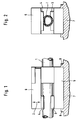
- the pretensioning device comprises a first jaw 3 and a second jaw 4, which have a mutual space in which a hose 1 is clamped in such a way that the hose has an essentially elliptical or compressed, but does not have a circular cross section.
- the underside of the second jaw 4 is designed in the form of a flat surface, while the first jaw 3 has a part-circular groove in which the hose 1 can be inserted.
- the biasing force represented by the double arrows 2 loads the first and the second jaw 3, 4 against each other, so that the hose 1 is deformed.
- the first jaw 3 is mounted on a carrier 5 which is firmly connected to the hose 1, for example by gluing.
- the carrier 5 is removably arranged on a yoke 6.
- the yoke 6 supports the jaw 4 so that it can be biased perpendicular to the hose 1 against the hose 1, as shown by the pretensioning force arrow 2.
- the measuring device can also be introduced between the second jaw 4 and the yoke 6.
- the positioning and fixing of the hose 1 in the measuring device 7 is carried out by the carrier 5 fastened to the hose 1, which engages in the fastenings 8 on the measuring device 7.
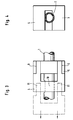
- the second exemplary embodiment shown in FIGS. 3 and 4 differs from the exemplary embodiment according to FIGS 1 and 2 in that the first and second jaws 3, 4 are integrally connected to one another and form a substantially U-shaped biasing element, as shown in Fig. 4 qe.
- the prestressing element can be displaced in the longitudinal direction of the hose 1 by means of one or more bolts 8 which are displaceably guided in the groove or grooves 9 of the carrier 5.
- the broken line shows, for example, the pretensioning state of the first and second jaws 3, 4, while the solid line shows a pushed-back state of the first and second jaws, so that a hose area 10 is released for pressure measurement in order to work on this hose area to arrange the pressure measuring jaws.
- the positioning and fixation of the measuring device 7 on the hose 1 is carried out by the carrier 5 firmly attached to the hose.
- the device according to the invention can thus be attached to the hose in a very simple manner during assembly and remains on the hose until the actual measuring process begins.
Landscapes
- Physics & Mathematics (AREA)
- General Physics & Mathematics (AREA)
- Measuring Fluid Pressure (AREA)
- Infusion, Injection, And Reservoir Apparatuses (AREA)
- External Artificial Organs (AREA)
- Investigating Strength Of Materials By Application Of Mechanical Stress (AREA)
Description
Die Erfindung bezieht sich auf ein Verfahren und eine Meßanordnung zur Messung eines Innendrucks in einem Schlauch und im speziellen auf ein Verfahren, bei welchem der Schlauch mit einer vorgegebenen Vorspannkraft senkrecht zur Schlauchachse den Schlauch verformend vorgespannt wird und Änderungen des Innendrucks durch Änderungen der Vorspannkraft bestimmt werden.The invention relates to a method and a measuring arrangement for measuring an internal pressure in a hose and in particular to a method in which the hose is prestressed to deform the hose with a predetermined pretensioning force perpendicular to the hose axis and changes in the internal pressure are determined by changes in the pretensioning force .
Bei vielen medizinischen Anwendungszwecken ist es erforderlich, den Druck in einem durchströmten Schlauch zu ermitteln. Das durch den Schlauch strömende Medium kann dabei beispielsweise Blut sein, in anderen Anwendungsfällen ist es jedoch auch möglich, daß der Druck einer sonstigen Flüssigkeit wie beispielsweise Dialysierflüssigkeit, einer mit Medikamenten versehenen Flüssigkeit oder einer Nährlösung bestimmt werden muß.For many medical applications, it is necessary to determine the pressure in a hose through which flow is flowing. The medium flowing through the tube can be blood, for example, but in other applications it is also possible that the pressure of another liquid such as dialysis liquid, a liquid provided with medication or a nutrient solution must be determined.
Insbesondere bei einem extrakorporalen Blutkreislauf eines Dialysegerätes ist es aus Sicherheitsgründen erforderlich, den Druck in dem System zu überwachen. Üblicherweise reicht auf der arteriellen Seite im einfachsten Fall ein sogenannter Druck-Kissenschalter aus, während auf der venösen Seite eine hohe Anzeigegenauigkeit erforderlich ist. Ein typischer Wert für den Meßbereich beträgt 0 bis + 40 kPa (0 bis 300 mm Hg). Die Auslösewerte liegen beispielsweise bei + / - kPa (7,5 mm Hg).In the case of an extracorporeal blood circuit of a dialysis machine in particular, it is necessary for safety reasons to monitor the pressure in the system. In the simplest case, a so-called pressure pad switch is usually sufficient on the arterial side, while a high level of display accuracy is required on the venous side. A typical value for the measuring range is 0 to + 40 kPa (0 to 300 mm Hg). The trigger values are, for example, +/- kPa (7.5 mm Hg).
Aus dem Stand der Technik ist es bekannt, zur Druckmessung in einem Schlauch mittels eines T-Stückes eine Stichleitung an dem Schlauch anzuschließen, welche zum Teil mit Luft gefüllt ist. Am freien Ende der Druck-Stichleitung ist ein Hydrophobfilter vorgesehen, um Kontaminationen zu vermeiden. Das Schlauchende ist weiterhin üblicherweise mittels einer genormten Luer-Lock-Kupplung mit einem Drucksensor gekoppelt. Daraus ergibt sich der Nachteil, daß ein relativ aufwendiges Schlauchsystem mit dem T-Stück erforderlich ist, wobei weiterhin zusätzlich der Hydrophobfilter und der Luer-Lock-Adapter erforderlich sind. Weiterhin ist es für das Bedienungspersonal umständlich, das Schlauchsystem an den Drucksensor bzw. Monitor anzuschließen. Insbesondere bei ungeübtem Personal besteht weiterhin die Gefahr, daß der arterielle und der venöse Drucksensor vertauscht werden, so daß das Steuerungssystem aufgrund falscher Datenvorgaben arbeitet. Ein weiterer, wesentlicher Nachteil dieser Ausgestaltungsform liegt darin, daß sich in der Stichleitung das Fluid, welches den Schlauch durchströmt, sammelt. Bei der Durchströmung der Stichleitung mit Blut besteht dabei die Gefahr, daß das Blut gerinnt, da in der Stichleitung im wesentlichen keine Strömung vorliegt.It is known from the prior art to connect a spur line to the hose, which is partly filled with air, for measuring pressure in a hose by means of a T-piece. A hydrophobic filter is provided at the free end of the pressure branch line to avoid contamination. The hose end is also usually by means of a standardized Luer lock coupling coupled with a pressure sensor. This results in the disadvantage that a relatively complex hose system with the T-piece is required, the hydrophobic filter and the Luer lock adapter also being required. Furthermore, it is cumbersome for the operating personnel to connect the hose system to the pressure sensor or monitor. In the case of inexperienced personnel in particular, there is still the risk that the arterial and venous pressure sensors may be interchanged, so that the control system operates due to incorrect data specifications. Another major disadvantage of this embodiment is that the fluid that flows through the hose collects in the branch line. When blood flows through the stub, there is a risk that the blood will clot since there is essentially no flow in the stub.
Aus dem Stand der Technik sind weiterhin Druckschalter bekannt, welche an einem Schlauch eines Infusionsgerätes angebracht sind. Derartige Druckschalter dienen jedoch wegen der großen Meßungenauigkeit nur als schaltendes, nicht jedoch als messendes Element. Eine Druckmessung ermöglicht aber eine Verfahrensüberwachung und -steuerung bei der Infusion von Flüssigkeiten.Pressure switches are also known from the prior art, which are attached to a hose of an infusion device. However, because of the great measurement inaccuracy, such pressure switches only serve as a switching element, but not as a measuring element. A pressure measurement enables process monitoring and control during the infusion of liquids.
Es sind weiterhin Druckmeßvorrichtungen vorgeschlagen worden, bei welchen der Schlauch von seinem runden Querschnitt in einen elliptischen Querschnitt verformt wird, wobei diese Verformung durch Aufbringen einer Vorspannkraft erfolgt. Druckänderungen im Inneren des Schlauches führen zu einer Veränderung der Vorspannkraft, welche gemessen und in Relation zu dem Innendruck in dem Schlauch gesetzt werden kann. Bei dieser vorgeschlagenen Vorgehensweise ist es ungünstig, daß das Kunststoffmaterial systembedingt zu Kriechvorgängen neigt, so daß bei einem längeren Meßvorgang, zusätzlich zu der Temperaturabhängigkeit, die den E-Modul des Kunststoffschlauches beeinflußt, ein Langzeit-Kriechen des Schlauchmateriales auftritt. Dies führt bei längerer Meßzeit zum Abfall der Einspannkraft bei gleichbleibendem Einspannweg und gleichbleibendem Innendruck in dem Schlauch. Das Langzeit-Kriechverhalten hängt u. a. von der Dimensionierung des Schlauches und von dem Kunststoffmaterial ab. Insbesondere bei PVC-Schläuchen, welche wegen ihres ökonomischen Vorteils besonders häufig bei medizinischen Schlauchanordnungen verwendet werden, ergeben sich Kriechwerte, welche in der Größenordnung des zu messenden Drucksignales liegen, so daß eine derartige Druckmessung vielfach nicht möglich ist.Pressure measuring devices have also been proposed in which the tube is deformed from its round cross-section into an elliptical cross-section, this deformation taking place by applying a prestressing force. Changes in pressure in the interior of the hose lead to a change in the pretensioning force, which can be measured and related to the internal pressure in the hose. With this proposed procedure, it is disadvantageous that the plastic material tends to creep due to the system, so that a long-term creeping of the hose material occurs in addition to the temperature dependence, which influences the modulus of elasticity of the plastic hose. With a longer measuring time, this leads to a drop the clamping force with constant clamping path and constant internal pressure in the hose. The long-term creep behavior depends, among other things, on the dimensioning of the hose and the plastic material. In particular in the case of PVC hoses, which are used particularly frequently in medical hose arrangements because of their economic advantage, creep values result which are in the order of magnitude of the pressure signal to be measured, so that such a pressure measurement is often not possible.
Aus der DE-C1 38 38 689 ist eine Druckmeßvorrichtung bekannt, bei welcher ein Schlauch zwischen einer feststehenden Backe und einer federnd belasteten Backe elastisch verformend eingespannt ist. Wird der Schlauch mit Druck beaufschlagt, verformt er sich und bewegt dabei die federnd belastete Backe. Aus dieser Bewegung wird der Druck im Schlauch ermittelt. Diese Vorrichtung hat allerdings den Nachteil, daß ein Langzeit-Kriechen des Schlauchmateriales das Meßergebnis verfälscht.From DE-C1 38 38 689 a pressure measuring device is known in which a hose is clamped elastically deforming between a fixed jaw and a spring-loaded jaw. When pressure is applied to the hose, it deforms and moves the spring-loaded jaw. The pressure in the hose is determined from this movement. However, this device has the disadvantage that long-term creeping of the hose material falsifies the measurement result.
Der Erfindung liegt die Aufgabe zugrunde, ein Verfahren und eine Meßanordnung eingangs genannten Art zu schaffen, welche bei einfachem Aufbau und einfacher, leichter Handhabbarkeit eine zuverlässige Druckmessung auch bei Schläuchen ermöglichen, deren Material ein Kriechverhalten aufweist.The invention has for its object to provide a method and a measuring arrangement of the type mentioned which, with a simple structure and simple, easy handling, enable reliable pressure measurement even with hoses whose material has a creep behavior.
Hinsichtlich des Verfahrens wird die Aufgabe erfindungsgemäß dadurch gelöst, daß der Schlauch vor Durchführung der Druckmessung über einen längeren Zeitraum verformend vorgespannt wird.With regard to the method, the object is achieved according to the invention in that the hose is prestressed over a longer period of time before the pressure measurement is carried out.
Das erfindungsgemäße Verfahren zeichnet sich durch eine Reihe erheblicher Vorteile aus. Da der Druck bereits über einen langen Zeitraum vor Aufbringung des eigentlichen Prüfdruckes auf den Schlauch aufgebracht wird, kann das Langzeit-Kriechen des Schlauchmateriales bereits rechtzeitig einsetzen und ist somit im wesentlichen abgeschlossen, bis der eigentliche Meßvorgang stattfindet. Bei üblichen PVC-Schläuchen, welche im medizinischen Bereich verwendet werden, klingt der Kriechvorgang innerhalb weniger Stunden ab, so daß beispielsweise nach einer Einspannzeit von 5 Tagen nicht mehr mit einem Langzeit-Kriechen des Schlauchmateriales zu rechnen ist. Somit läßt sich diese Fehlerquelle der Messung durch das erfindungsgemäße Verfahren gänzlich eliminieren.The method according to the invention is distinguished by a number of considerable advantages. Since the pressure has been applied to the hose for a long time before the actual test pressure is applied, the long-term creeping of the hose material can begin in good time and is therefore essentially complete until the actual measuring process takes place. With conventional PVC hoses that are used in the medical field, the creeping process subsides within a few hours, so that, for example, after a clamping time of 5 days, long-term creeping of the hose material is no longer to be expected. This source of error in the measurement can thus be completely eliminated by the method according to the invention.
Da die Vorspannung des Schlauches bereits bei seiner Konfektionierung erfolgen kann, liegt zwischen der Fertigstellung des Schlauchsystemes und der Anwendung ein ausreichend langer Zeitraum für das Abklingen des Kriechens.Since the hose can be pre-tensioned when it is assembled, there is a sufficiently long time between completion of the hose system and use Period for the creep to subside.
Als Vorteil ergibt sich somit, daß eine sehr genaue Druckmessung am Schlauch vorgenommen werden kann, ohne daß das Schlauchmaterial durch Kriechvorgänge Meßfehler herbeiruft. Im Vergleich zu bisher bekannten Systemen ergibt sich somit eine sehr einfache Handhabung des Schlauchsystemes, da weiterhin ein kostengünstiges PVC-Material verwendbar ist, sind die Gesamtkosten ausgesprochen niedrig. Im Vergleich zu den Meßverfahren, bei welchen ein Druck in einem Abzweigschlauch gemessen wird, besteht eine sehr günstige Strömungsführung, weiterhin wird jegliche Kontaminationsgefahr ausgeräumt.The advantage thus arises that a very precise pressure measurement can be carried out on the hose without the hose material causing measurement errors due to creeping processes. Compared to previously known systems, this results in very simple handling of the hose system, since an inexpensive PVC material can still be used, the overall costs are extremely low. In comparison to the measuring methods, in which a pressure is measured in a branch hose, the flow is very favorable, furthermore any risk of contamination is eliminated.
In einer günstigen Ausgestaltung der Erfindung wird der Schlauch in gleicher Weise wie bei der nachfolgenden Messung über den längeren Zeitraum vorgespannt. Es erfolgt somit eine gleiche geometrische Verformung des Schlauches, so daß Änderungen in der Schlauchgeometrie zwischen dem Vorspannvorgang und dem eigentlichen Meßvorgang nicht auftreten. Weiterhin ist es besonders günstig, wenn die Endvorspannung die gleiche Druckbelastung ergibt, wie die Einspannung des Schlauches bei dem nachfolgenden Meßvorgang.In a favorable embodiment of the invention, the hose is prestressed over the longer period in the same way as in the subsequent measurement. There is thus an identical geometric deformation of the hose, so that changes in the hose geometry between the prestressing process and the actual measuring process do not occur. Furthermore, it is particularly advantageous if the final prestress results in the same pressure load as the clamping of the hose in the subsequent measuring process.
Günstig ist es weiterhin, wenn der Schlauch zumindest bis zum Abklingen des Langzeit-Kriechens vorgespannt wird, er kann jedoch auch über einen wesentlich längeren Zeitraum mit der Vorspannung beaufschlagt sein, da dies nicht zu weiteren Änderungen des Schlauchmateriales führt. Die Vorspannung muß bis kurz vor Beginn des Meßvorgangs erhalten bleiben.It is also expedient if the hose is pretensioned at least until the long-term creep subsides, but it can also be pretensioned over a considerably longer period, since this does not lead to further changes in the hose material. The preload must be maintained until shortly before the measuring process begins.
Erfindungsgemäß wird zumindest der zur Messung benötigte Teil des Schlauches vorgespannt, es ist jedoch auch möglich, einen größeren Schlauchbereich vorzuspannen und damit den Kriechvorgang auszusetzen.According to the invention, at least the part of the hose required for the measurement is pretensioned, but it is also possible to pretension a larger hose area and thus to suspend the creeping process.
Bezüglich der Vorrichtung zum Vorspannen des Schlauchs, die Bestandteil der erfindungsgemäßen Meßanordnung ist, ist zur Lösung der zugrundeliegenden Aufgabe vorgesehen, daß diese eine erste und eine zweite Backe umfaßt, mit Hilfe derer der Schlauch eingespannt werden kann. Die erste und zweite Backe weisen zueinander einen Abstand auf, welcher kleiner ist, als der unverformte Durchmesser des Schlauches, welcher jedoch im wesentlichen dem Abstand entspricht, welcher durch die beiden Meßbacken während des Meßvorganges aufgebracht wird. Es liegen somit erfindungsgemäß identische Vorspann-Belastungsverhältnisse vor, wie bei dem eigentlichen Meßvorgang, so daß der Schlauch in gleicher Weise verformt und in seinem Querschnitt verändert wird.With regard to the device for pretensioning the hose, which is part of the measuring arrangement according to the invention, to solve the underlying problem it is provided that it comprises a first and a second jaw, by means of which the hose is clamped can. The first and second jaws are at a distance from one another which is smaller than the undeformed diameter of the hose, but which essentially corresponds to the distance which is applied by the two measuring jaws during the measuring process. According to the invention, there are identical preload-load conditions as in the actual measuring process, so that the hose is deformed in the same way and its cross-section is changed.
Um die Vorspannvorrichtung bereits während der Herstellung der Schlauchanordnung an der entsprechenden Stelle an dem Schlauch anbringen zu können, ist es besonders günstig, wenn die erste und die zweite Backe mittels eines Trägers gelagert sind, welcher fest an dem Schlauch vorgesehen ist. Zur nachfolgenden Durchführung des Meßvorganges ist es dann lediglich erforderlich, die zweite oder die erste und die zweite Backe von dem entsprechenden Schlauchstück zu entfernen. Dies ist beispielsweise dadurch möglich, daß die erste und zweite Backe gegeneinander bewegbar am Träger gelagert sind. Es ist jedoch auch möglich, die erste und die zweite Backe einstückig miteinander auszubilden, so daß sich ein im wesentlichen Uförmiges Klemmelement ergibt, welches längsverschiebbar mittels des Trägers an dem Schlauch gelagert ist. Das Klemmelement kann somit zur Durchführung der eigentlichen Druckmessung längs des Schlauches verschoben werden.In order to be able to attach the pretensioning device to the corresponding point on the hose during the manufacture of the hose arrangement, it is particularly expedient if the first and second jaws are mounted by means of a carrier which is provided on the hose. For the subsequent execution of the measuring process, it is then only necessary to remove the second or the first and the second jaw from the corresponding piece of hose. This is possible, for example, in that the first and second jaws are mounted on the carrier so as to be movable relative to one another. However, it is also possible to form the first and second jaws in one piece with one another, so that there is an essentially U-shaped clamping element which is mounted on the hose so as to be longitudinally displaceable by means of the carrier. The clamping element can thus be moved along the hose to carry out the actual pressure measurement.
Im folgenden wird die Erfindung anhand eines Ausführungsbeispiels in Verbindung mit der Zeichnung beschrieben. Dabei zeigt:
- Fig. 1
- eine Seitenansicht eines ersten Ausführungsbeispiels der erfindungsgemäßen Vorspannvorrichtung,
- Fig. 2
- eine stirnseitige Ansicht des in Fig. 1 gezeigten Ausführungsbeispiels,
- Fig. 3
- eine Draufsicht auf ein zweites Ausführungsbeispiel der erfindungsgemäßen Vorrichtung und
- Fig. 4
- eine stirnseitige Ansicht, auf die in Fig. 3 linke Seite des in Fig. 3 gezeigten Ausführungsbeispiels.
- Fig. 1
- a side view of a first embodiment of the pretensioning device according to the invention,
- Fig. 2
- 2 shows an end view of the exemplary embodiment shown in FIG. 1,
- Fig. 3
- a plan view of a second embodiment of the device according to the invention and
- Fig. 4
- an end view, on the left in Fig. 3 of the embodiment shown in Fig. 3.
Die erfindungsgemäße Vorspannvorrichtung umfaßt gemäß dem in den Fig. 1 und 2 gezeigten Ausführungsbeispiel eine erste Backe 3 und eine zweite Backe 4, welche zueinander einen Freiraum aufweisen, in welchem ein Schlauch 1 so eingespannt ist, daß der Schlauch einen im wesentlichen elliptischen oder zusammengedrückten, nicht jedoch kreisförmigen Querschnitt aufweist. Bei dem gezeigten Ausführungsbeispiel ist die Unterseite der zweiten Backe 4 in Form einer ebenen Fläche ausgebildet, während die erste Backe 3 eine teilkreisförmige Nut aufweist, in welche der Schlauch 1 eingelegt werden kann. Die durch die Doppelpfeile 2 dargestellte Vorspannkraft belastet die erste und die zweite Backe 3, 4 gegeneinander, so daß der Schlauch 1 verformt wird. Die erste Backe 3 ist, wie in Fig. 1 und 2 schematisch gezeigt, an einem Träger 5 gelagert, welcher fest mit dem Schlauch 1 verbunden ist, beispielsweise durch Verkleben. Der Träger 5 ist an ein Joch 6 abnehmbar angeordnet. Das Joch 6 trägt die Backe 4, so daß diese, wie durch den Vorspannkraft-Pfeil 2 gezeigt, senkrecht zu dem Schlauch 1 gegen diesen vorgespannt werden kann. Bei Durchführung der Messung ist es beispielsweise lediglich erforderlich, die zweite Backe 4 durch eine Meßbacke zu ersetzen. Alternativ hierzu kann jedoch auch die Meßvorrichtung zwischen die zweite Backe 4 und das Joch 6 eingebracht werden.According to the embodiment shown in FIGS. 1 and 2, the pretensioning device according to the invention comprises a
Die Positionierung und Fixierung des Schlauchs 1 in der Meßvorrichtung 7 erfolgt durch den am Schlauch 1 befestigten Träger 5, der in die Befestigungen 8 an der Meßvorrichtung 7 eingreift.The positioning and fixing of the
Das zweite, in den Fig. 3 und 4 gezeigte Ausführungsbeispiel unterscheidet sich von dem Ausführungsbeispiel gemäß den Fig. 1 und 2 dadurch, daß die erste und zweite Backe 3, 4 einstückig miteinander verbunden sind und ein im wesentlichen U-förmiges Vorspannelement bilden, so wie dies in Fig. 4 qezeigt ist. Das Vorspannelement ist über einen oder mehrere Bolzen 8, welche in den oder die Nuten 9 des Trägers 5 verschiebbar geführt sind, in Längsrichtung des Schlauches 1 verschiebbar. In Fig. 3 zeigt die gestrichelte Darstellung beispielsweise den Vorspannzustand der ersten und zweiten Backe 3, 4, während mit der ausgezogenen Linie ein zurückgeschobener Zustand der ersten und zweiten Backe dargestellt ist, so daß ein Schlauchbereich 10 zur Druckmessung freigegeben wird, um an diesem Schlauchbereich die Druckmeßbacken anzuordnen.The second exemplary embodiment shown in FIGS. 3 and 4 differs from the exemplary embodiment according to FIGS 1 and 2 in that the first and
Die Positionierung und Fixierung der Meßvorrichtung 7 am Schlauch 1 erfolgt durch den fest am Schlauch befestigten Träger 5.The positioning and fixation of the measuring
Die erfindungsgemäße Vorrichtung kann somit in sehr einfacher Weise bereits bei der Konfektionierung des Schlauches an diesem angebracht werden und verbleibt an dem Schlauch, bis der eigentliche Meßvorgang beginnt.The device according to the invention can thus be attached to the hose in a very simple manner during assembly and remains on the hose until the actual measuring process begins.
Die Erfindung ist nicht auf die gezeigten Ausführungsbeispiele beschränkt, vielmehr ergeben sich für den Fachmann im Rahmen der Erfindung vielfältige Abwandlungs- und Modifikationsmöglichkeiten.The invention is not limited to the exemplary embodiments shown, rather there are various modification and modification possibilities for the person skilled in the art within the scope of the invention.
Claims (9)
- A method for measuring an internal pressure in a flexible tube, in which said flexible tube (1) is biased at a given biasing forcing in a direction perpendicular to the tube axis, so that said flexible tube (1) is deformed, and changes in the internal pressure are determined through variations of the biasing force, characterized in that said flexible tube (1) is deformingly biased before the pressure measurement is carried out at least until long-time creep dies away.
- A method according to claim 1, characterized in that said flexible tube (1) is biased in the same way as in the subsequent measurement at least until long-time creep dies away.
- A method according to any one of claims 1 to 3, characterized in that at least the part of said flexible tube (1) required for the measurement is biased.
- A method according to any one of claims 1 to 4, characterized in that said tube (1) is biased at the same pressure load as during the measuring operation.
- An apparatus for measuring an internal pressure in a flexible tube with a measuring device (7) having a pressure measuring element for measuring the changes of the biasing force applied to said flexible tube (1) and a means for biasing said flexible tube (1) perpendicular to the tube axis until long-time creep dies away, further having a first and a second jaw (3, 4), said jaws being adapted to be spaced apart from each other at a distance which is smaller than the undeformed diameter of said flexible tube (1), with said first and/or second jaw (3, 4) being embodied such that it is interchangeable by the pressure measuring element of the measuring device.
- An apparatus according to claim 5, characterized in that said first and second jaws (3, 4) are disposed on a carrier mounted on said flexible tube (1), in such a way that they are movable relative to each other.
- An apparatus according to claim 5, characterized in that said first and second jaws (3, 4) are integrally connected to each other and displaceably arranged along said flexible tube (1) on a carrier (5) mounted on said flexible tube (1).
- An apparatus according to claim 5, characterized in that the biasing element consisting of said jaws (3, 4) is guided via one or several pins (8) in one or several grooves (9) provided in said carrier (5).
- An apparatus according to claim 5, wherein said carrier (5) serves to position said flexible tube (1) on said measuring device (7).
Applications Claiming Priority (2)
| Application Number | Priority Date | Filing Date | Title |
|---|---|---|---|
| DE4106444 | 1991-02-28 | ||
| DE4106444A DE4106444C1 (en) | 1991-02-28 | 1991-02-28 |
Publications (2)
| Publication Number | Publication Date |
|---|---|
| EP0501234A1 EP0501234A1 (en) | 1992-09-02 |
| EP0501234B1 true EP0501234B1 (en) | 1996-09-11 |
Family
ID=6426176
Family Applications (1)
| Application Number | Title | Priority Date | Filing Date |
|---|---|---|---|
| EP92102374A Expired - Lifetime EP0501234B1 (en) | 1991-02-28 | 1992-02-13 | Method and apparatus for measuring internal pressure in a tube |
Country Status (4)
| Country | Link |
|---|---|
| EP (1) | EP0501234B1 (en) |
| JP (1) | JPH0587659A (en) |
| DE (2) | DE4106444C1 (en) |
| ES (1) | ES2091344T3 (en) |
Cited By (3)
| Publication number | Priority date | Publication date | Assignee | Title |
|---|---|---|---|---|
| DE19747254A1 (en) * | 1997-10-25 | 1999-05-06 | Gerhard Prof Dr Ing Silber | Non-invasive inner pressure measurement in elastic vessels deformed by external application of force |
| DE19918714A1 (en) * | 1999-04-26 | 2000-11-16 | Gerhard Silber | Process for non-invasive internal pressure measurement in elastic vessels |
| US8858185B2 (en) | 2010-06-23 | 2014-10-14 | Hospira, Inc. | Fluid flow rate compensation system using an integrated conductivity sensor to monitor tubing changes |
Families Citing this family (24)
| Publication number | Priority date | Publication date | Assignee | Title |
|---|---|---|---|---|
| DE19901078C1 (en) | 1999-01-14 | 2000-02-17 | Polaschegg Hans Dietrich | Monitoring system for fistula or graft has instruments to detect pulse from patient's heart or external blood circulation pump |
| DE102006033827B4 (en) * | 2006-07-19 | 2010-01-07 | Fresenius Medical Care Deutschland Gmbh | Method for pressure measurement in a hose, device for carrying out the method and use of the method or the device |
| US8517990B2 (en) | 2007-12-18 | 2013-08-27 | Hospira, Inc. | User interface improvements for medical devices |
| DE102009039958A1 (en) * | 2009-08-28 | 2011-03-10 | Bernd Beck | Medical pressure transducer and contact holder |
| CA2844807C (en) | 2011-08-19 | 2022-07-26 | Hospira, Inc. | Systems and methods for a graphical interface including a graphical representation of medical data |
| US10022498B2 (en) | 2011-12-16 | 2018-07-17 | Icu Medical, Inc. | System for monitoring and delivering medication to a patient and method of using the same to minimize the risks associated with automated therapy |
| AU2013239778B2 (en) | 2012-03-30 | 2017-09-28 | Icu Medical, Inc. | Air detection system and method for detecting air in a pump of an infusion system |
| EP2879733B1 (en) | 2012-07-31 | 2019-06-05 | ICU Medical, Inc. | Patient care system for critical medications |
| EP2737917B1 (en) * | 2012-11-29 | 2018-03-21 | Gambro Lundia AB | Extracorporeal blood circuit with non-invasive pressure sensor |
| AU2014268355B2 (en) | 2013-05-24 | 2018-06-14 | Icu Medical, Inc. | Multi-sensor infusion system for detecting air or an occlusion in the infusion system |
| ES2838450T3 (en) | 2013-05-29 | 2021-07-02 | Icu Medical Inc | Infusion set that uses one or more sensors and additional information to make an air determination relative to the infusion set |
| EP3003442B1 (en) | 2013-05-29 | 2020-12-30 | ICU Medical, Inc. | Infusion system and method of use which prevents over-saturation of an analog-to-digital converter |
| US10342917B2 (en) | 2014-02-28 | 2019-07-09 | Icu Medical, Inc. | Infusion system and method which utilizes dual wavelength optical air-in-line detection |
| CA2947045C (en) | 2014-05-29 | 2022-10-18 | Hospira, Inc. | Infusion system and pump with configurable closed loop delivery rate catch-up |
| US11344668B2 (en) | 2014-12-19 | 2022-05-31 | Icu Medical, Inc. | Infusion system with concurrent TPN/insulin infusion |
| US10850024B2 (en) | 2015-03-02 | 2020-12-01 | Icu Medical, Inc. | Infusion system, device, and method having advanced infusion features |
| US11246985B2 (en) | 2016-05-13 | 2022-02-15 | Icu Medical, Inc. | Infusion pump system and method with common line auto flush |
| AU2017277804B2 (en) | 2016-06-10 | 2022-05-26 | Icu Medical, Inc. | Acoustic flow sensor for continuous medication flow measurements and feedback control of infusion |
| US10089055B1 (en) | 2017-12-27 | 2018-10-02 | Icu Medical, Inc. | Synchronized display of screen content on networked devices |
| EP3773793A1 (en) * | 2018-03-26 | 2021-02-17 | TERUMO Kabushiki Kaisha | Biological component collection system and flow path internal pressure acquisition method |
| WO2020090544A1 (en) * | 2018-11-01 | 2020-05-07 | Terumo Kabushiki Kaisha | Biological component collection system and circuit internal pressure acquisition method |
| US11278671B2 (en) | 2019-12-04 | 2022-03-22 | Icu Medical, Inc. | Infusion pump with safety sequence keypad |
| CA3189781A1 (en) | 2020-07-21 | 2022-01-27 | Icu Medical, Inc. | Fluid transfer devices and methods of use |
| US11135360B1 (en) | 2020-12-07 | 2021-10-05 | Icu Medical, Inc. | Concurrent infusion with common line auto flush |
Family Cites Families (8)
| Publication number | Priority date | Publication date | Assignee | Title |
|---|---|---|---|---|
| US3418853A (en) * | 1966-01-10 | 1968-12-31 | Statham Instrument Inc | Blood pressure transducer |
| SE403004B (en) * | 1976-12-03 | 1978-07-24 | Gambro Ab | PRESSURE GUARD |
| AT374007B (en) * | 1980-03-19 | 1984-03-12 | List Hans | MEASURING VALUES FOR MEASURING MECHANICAL SIZES ON HOLLOW BODIES |
| GB2198239A (en) * | 1986-11-27 | 1988-06-08 | Ford Motor Co | Monitoring fluid pressure in a flexible pipe |
| JPH01249064A (en) * | 1988-03-30 | 1989-10-04 | Nikkiso Co Ltd | Detection of closed state of infusion pipe and device therefor |
| DE3838689C1 (en) * | 1988-11-15 | 1990-06-28 | Fresenius Ag, 6380 Bad Homburg, De | Method for the continuous measurement of the pressure in a flexible fluid line for medical purposes, as well as a device for carrying out the method |
| DE3918142A1 (en) * | 1989-05-31 | 1990-12-13 | Wiest Peter P | PRESSURE MEASURING DEVICE FOR FLUIDS FLOWING IN LINE |
| DE3918534A1 (en) * | 1989-06-07 | 1990-12-20 | Braun Melsungen Ag | PRESSURE SENSOR FOR INFUSION PIPES |
-
1991
- 1991-02-28 DE DE4106444A patent/DE4106444C1/de not_active Expired - Lifetime
-
1992
- 1992-02-13 DE DE59207075T patent/DE59207075D1/en not_active Expired - Fee Related
- 1992-02-13 EP EP92102374A patent/EP0501234B1/en not_active Expired - Lifetime
- 1992-02-13 ES ES92102374T patent/ES2091344T3/en not_active Expired - Lifetime
- 1992-02-28 JP JP4078409A patent/JPH0587659A/en active Pending
Cited By (6)
| Publication number | Priority date | Publication date | Assignee | Title |
|---|---|---|---|---|
| DE19747254A1 (en) * | 1997-10-25 | 1999-05-06 | Gerhard Prof Dr Ing Silber | Non-invasive inner pressure measurement in elastic vessels deformed by external application of force |
| DE19747254C2 (en) * | 1997-10-25 | 2000-01-13 | Gerhard Silber | Process for non-invasive internal pressure measurement in elastic vessels |
| DE19918714A1 (en) * | 1999-04-26 | 2000-11-16 | Gerhard Silber | Process for non-invasive internal pressure measurement in elastic vessels |
| DE19918714C2 (en) * | 1999-04-26 | 2001-07-26 | Gerhard Silber | Process for non-invasive internal pressure measurement in elastic vessels |
| US6857318B1 (en) | 1999-04-26 | 2005-02-22 | Baxter International Inc. | Method for the non-invasive measurement of an internal pressure |
| US8858185B2 (en) | 2010-06-23 | 2014-10-14 | Hospira, Inc. | Fluid flow rate compensation system using an integrated conductivity sensor to monitor tubing changes |
Also Published As
| Publication number | Publication date |
|---|---|
| JPH0587659A (en) | 1993-04-06 |
| DE4106444C1 (en) | 1992-07-23 |
| DE59207075D1 (en) | 1996-10-17 |
| EP0501234A1 (en) | 1992-09-02 |
| ES2091344T3 (en) | 1996-11-01 |
Similar Documents
| Publication | Publication Date | Title |
|---|---|---|
| EP0501234B1 (en) | Method and apparatus for measuring internal pressure in a tube | |
| DE4204754C2 (en) | Pipe and valve assembly for use in breathing gas test equipment | |
| EP0685721B1 (en) | Device for measuring the pressure of a medium | |
| DE2431805C3 (en) | Flow control device | |
| DE2720210A1 (en) | DEVICE FOR CALIBRATING A SENSOR DURING THE MEASUREMENT IN A CONTINUOUSLY FLOWING LIQUID SAMPLE | |
| DE202007013096U1 (en) | Syringe with exchangeable needle | |
| EP0400587A2 (en) | Pressure measuring device for fluids flowing in pipes | |
| EP2950848B1 (en) | Connecting device with clamping device for connection to an arrangement for closing off flow paths and monitoring the state of the clamping device and method therefor | |
| EP0249617B1 (en) | Regulating clamp for flexible infusion tubes | |
| DE102020216084A1 (en) | Material testing device for bending tests and method for carrying out a bending test | |
| DE2900896C2 (en) | Thread measuring device | |
| EP1272785A2 (en) | Method and device for tightly fixing a piece of flexible tubing consisting of an elastomer material to a connecting part | |
| DE2601581A1 (en) | FLOW ADJUSTMENT DEVICE | |
| EP3214413B1 (en) | Device and method for applying a solid measure | |
| WO2015110387A1 (en) | Method and device for controlling the flow through a medical infusion line | |
| DE4228566A1 (en) | METHOD FOR BENDING DEFORMABLE BODY | |
| DE3820543A1 (en) | Apparatus and process for fastening a sleeve-shaped component on a flexible tube | |
| DE2816186A1 (en) | Test probe for iso-volumetric pressure measurement appts. - has chamber with diaphragm connected to another diaphragm and includes micro-cannula probe | |
| DE102004012801B3 (en) | Apparatus to control and inflate a balloon catheter, with a piston/cylinder unit in a release mounting at a housing, has a pressure monitor to register the pressure continuously | |
| DD259688A5 (en) | RECHARGEABLE LOW-PRESSURE COLONS FOR PRAEPARATIVE CHROMATOGRAPHY | |
| DD158310A3 (en) | DEVICE FOR MEASURING SMALL FLUID QUANTITIES | |
| EP0495461A1 (en) | Device for measuring the strength of the human hand or finger | |
| EP0794373A1 (en) | Process and device for the determination of a safety valve set pressure | |
| WO2005092412A1 (en) | Adapter and pumping interface for measuring pressure on an infusion pump | |
| DE4141162A1 (en) | Mounting for attaching proximity switch to pressure medium cylinder - has clamp piece with different clamp jaw sets for mounting in one of two diametrically opposite positions |
Legal Events
| Date | Code | Title | Description |
|---|---|---|---|
| PUAI | Public reference made under article 153(3) epc to a published international application that has entered the european phase |
Free format text: ORIGINAL CODE: 0009012 |
|
| AK | Designated contracting states |
Kind code of ref document: A1 Designated state(s): DE ES FR GB IT |
|
| 17P | Request for examination filed |
Effective date: 19930216 |
|
| 17Q | First examination report despatched |
Effective date: 19940712 |
|
| GRAG | Despatch of communication of intention to grant |
Free format text: ORIGINAL CODE: EPIDOS AGRA |
|
| GRAH | Despatch of communication of intention to grant a patent |
Free format text: ORIGINAL CODE: EPIDOS IGRA |
|
| GRAH | Despatch of communication of intention to grant a patent |
Free format text: ORIGINAL CODE: EPIDOS IGRA |
|
| GRAA | (expected) grant |
Free format text: ORIGINAL CODE: 0009210 |
|
| AK | Designated contracting states |
Kind code of ref document: B1 Designated state(s): DE ES FR GB IT |
|
| GBT | Gb: translation of ep patent filed (gb section 77(6)(a)/1977) |
Effective date: 19960920 |
|
| REF | Corresponds to: |
Ref document number: 59207075 Country of ref document: DE Date of ref document: 19961017 |
|
| REG | Reference to a national code |
Ref country code: ES Ref legal event code: FG2A Ref document number: 2091344 Country of ref document: ES Kind code of ref document: T3 |
|
| ITF | It: translation for a ep patent filed |
Owner name: STUDIO TORTA SOCIETA' SEMPLICE |
|
| ET | Fr: translation filed | ||
| PGFP | Annual fee paid to national office [announced via postgrant information from national office to epo] |
Ref country code: GB Payment date: 19970120 Year of fee payment: 6 |
|
| PGFP | Annual fee paid to national office [announced via postgrant information from national office to epo] |
Ref country code: FR Payment date: 19970217 Year of fee payment: 6 |
|
| PGFP | Annual fee paid to national office [announced via postgrant information from national office to epo] |
Ref country code: ES Payment date: 19970228 Year of fee payment: 6 |
|
| PGFP | Annual fee paid to national office [announced via postgrant information from national office to epo] |
Ref country code: DE Payment date: 19970416 Year of fee payment: 6 |
|
| PLBE | No opposition filed within time limit |
Free format text: ORIGINAL CODE: 0009261 |
|
| STAA | Information on the status of an ep patent application or granted ep patent |
Free format text: STATUS: NO OPPOSITION FILED WITHIN TIME LIMIT |
|
| 26N | No opposition filed | ||
| PG25 | Lapsed in a contracting state [announced via postgrant information from national office to epo] |
Ref country code: GB Free format text: LAPSE BECAUSE OF NON-PAYMENT OF DUE FEES Effective date: 19980213 |
|
| PG25 | Lapsed in a contracting state [announced via postgrant information from national office to epo] |
Ref country code: ES Free format text: LAPSE BECAUSE OF EXPIRATION OF PROTECTION Effective date: 19980214 |
|
| PG25 | Lapsed in a contracting state [announced via postgrant information from national office to epo] |
Ref country code: FR Free format text: THE PATENT HAS BEEN ANNULLED BY A DECISION OF A NATIONAL AUTHORITY Effective date: 19980228 |
|
| GBPC | Gb: european patent ceased through non-payment of renewal fee |
Effective date: 19980213 |
|
| PG25 | Lapsed in a contracting state [announced via postgrant information from national office to epo] |
Ref country code: DE Free format text: LAPSE BECAUSE OF NON-PAYMENT OF DUE FEES Effective date: 19981103 |
|
| REG | Reference to a national code |
Ref country code: FR Ref legal event code: ST |
|
| REG | Reference to a national code |
Ref country code: ES Ref legal event code: FD2A Effective date: 20000201 |
|
| PG25 | Lapsed in a contracting state [announced via postgrant information from national office to epo] |
Ref country code: IT Free format text: LAPSE BECAUSE OF NON-PAYMENT OF DUE FEES;WARNING: LAPSES OF ITALIAN PATENTS WITH EFFECTIVE DATE BEFORE 2007 MAY HAVE OCCURRED AT ANY TIME BEFORE 2007. THE CORRECT EFFECTIVE DATE MAY BE DIFFERENT FROM THE ONE RECORDED. Effective date: 20050213 |