EP0498034A2 - System for monitoring a combustion apparatus - Google Patents
System for monitoring a combustion apparatus Download PDFInfo
- Publication number
- EP0498034A2 EP0498034A2 EP91115880A EP91115880A EP0498034A2 EP 0498034 A2 EP0498034 A2 EP 0498034A2 EP 91115880 A EP91115880 A EP 91115880A EP 91115880 A EP91115880 A EP 91115880A EP 0498034 A2 EP0498034 A2 EP 0498034A2
- Authority
- EP
- European Patent Office
- Prior art keywords
- combustion
- combustion apparatus
- memory
- monitor
- time
- Prior art date
- Legal status (The legal status is an assumption and is not a legal conclusion. Google has not performed a legal analysis and makes no representation as to the accuracy of the status listed.)
- Granted
Links
Images


Classifications
-
- F—MECHANICAL ENGINEERING; LIGHTING; HEATING; WEAPONS; BLASTING
- F23—COMBUSTION APPARATUS; COMBUSTION PROCESSES
- F23N—REGULATING OR CONTROLLING COMBUSTION
- F23N5/00—Systems for controlling combustion
- F23N5/26—Details
-
- F—MECHANICAL ENGINEERING; LIGHTING; HEATING; WEAPONS; BLASTING
- F23—COMBUSTION APPARATUS; COMBUSTION PROCESSES
- F23N—REGULATING OR CONTROLLING COMBUSTION
- F23N5/00—Systems for controlling combustion
- F23N5/24—Preventing development of abnormal or undesired conditions, i.e. safety arrangements
- F23N5/242—Preventing development of abnormal or undesired conditions, i.e. safety arrangements using electronic means
-
- F—MECHANICAL ENGINEERING; LIGHTING; HEATING; WEAPONS; BLASTING
- F23—COMBUSTION APPARATUS; COMBUSTION PROCESSES
- F23N—REGULATING OR CONTROLLING COMBUSTION
- F23N2223/00—Signal processing; Details thereof
-
- F—MECHANICAL ENGINEERING; LIGHTING; HEATING; WEAPONS; BLASTING
- F23—COMBUSTION APPARATUS; COMBUSTION PROCESSES
- F23N—REGULATING OR CONTROLLING COMBUSTION
- F23N2223/00—Signal processing; Details thereof
- F23N2223/08—Microprocessor; Microcomputer
-
- F—MECHANICAL ENGINEERING; LIGHTING; HEATING; WEAPONS; BLASTING
- F23—COMBUSTION APPARATUS; COMBUSTION PROCESSES
- F23N—REGULATING OR CONTROLLING COMBUSTION
- F23N2227/00—Ignition or checking
- F23N2227/12—Burner simulation or checking
-
- F—MECHANICAL ENGINEERING; LIGHTING; HEATING; WEAPONS; BLASTING
- F23—COMBUSTION APPARATUS; COMBUSTION PROCESSES
- F23N—REGULATING OR CONTROLLING COMBUSTION
- F23N2231/00—Fail safe
-
- F—MECHANICAL ENGINEERING; LIGHTING; HEATING; WEAPONS; BLASTING
- F23—COMBUSTION APPARATUS; COMBUSTION PROCESSES
- F23N—REGULATING OR CONTROLLING COMBUSTION
- F23N2231/00—Fail safe
- F23N2231/30—Representation of working time
Definitions
- This invention relates to a system for monitoring a combustion apparatus to prevent the combustion apparatus from developing serious trouble.
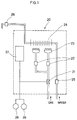
- Fig. 1 illustrates a combustion apparatus 20 which includes a parent electromagnetic valve 21, change-over electromagnetic valves 22, a burner 23, a heat collector 24, a sensor 25 for detecting the amount of water, a cock 26 for supplying hot water, and a control panel 27.
- a timer 28 is used to determine the cumulative total period of time for which the parent eletromagnetic valve 21 has been energized, while a counter 29 is used to determine how many times the parent eletromagnetic valve 21 has been energized.
- the timer 28 and the counter 29 thus serve to signal to the user the desirability of maintenance work of the combustion apparatus to prevent it from developing serious trouble. It is pretty expensive, however, to produce a combustion apparatus with such a monitoring system. In addition, such a monitoring system makes the combustion apparatus rather large.
- Fig. 2 depicts a monitoring system of the invention.
- the monitoring system is designated by reference numeral 4.
- the monitoring system 4 comprises a monitor 5, a memory 6, and a display 7.
- Reference numeral 1 designates a plug of a combustion apparatus to be monitored by the monitoring system 4; reference numeral 2, a power source of the combustion apparatus; and reference numeral 3, a controller for regulating the performance of the combustion apparatus.
- the power source 2 supplies power both to the controller 3 and to the monitoring system 4.
- the monitor 5 determines how many times the combustion apparatus have been used, or how many times combustion has taken place in the combustion apparatus.
- the monitor 5 also determines how long a time the combustion apparatus has been used in the aggregate. In other words, the monitor 5 also determines the cumulative total period of time for which combustion has occurred.
- the monitor 5 also determines what kinds of irregularities have developed during combustion and how many times each kind of irregularity has occurred in the aggregate. In other words, the monitor 5 also determines the cumulative number of times of occurrence of every kind of irregularity that has occurred since the combustion apparatus was used for the first time.
- the memory 6 automatically stores all these pieces of information obtained by the monitor 5.
- a volatile memory (not shown) is used in the memory 6.
- the memory 6 is provided with a backup power (not shown).
- the display 7 is capable of displaying the pieces of information stored in the memory 6. Also, the display 7 signals the user of the combustion apparatus to stop using the apparatus and instead perform maintenance work of it when such a desirability has come, as will be described below.
- Storing the pieces of information obtained by the monitor 6 is not the only function of the memory 6.
- the information stored in the memory 6 is not lost when the power 2 is turned off.
- both a reference number of times n of combustion and a reference cumulative period of time t of combustion are stored in the memory 6.
- the controller 3 starts to work and at the same time the monitor 5 starts to perform the foregoing three functions.
- the monitor 5 continues performing its functions during operation of the combustion apparatus. As described above, the information obtained by the monitor 5 is automatically stored in the memory 6.
- the monitor 5 performs its three functions.
- the memory 6 determines it.
- the display 7 operates to signal the user of the combustion apparatus to stop using it and instead perform maintenance work of it. Then, the user performs maintenance work of the apparatus.
- the user has finished the maintenance work, he activates a switch 9 which is connected to the monitor 5.
- the switch 9 is activated, the display 7 stops signaling the desirability of maintenance work and at the same time the reference values n and t are reset in the memory 6.
- the reference values n and t can be originally set such that the desirability of maintenance work will be signaled well before a number of times of combustion and a cumulative period of time of combustion are reached which may be assumed to result in a serious trouble of the combustion apparatus.
- the combustion apparatus can be effectively used without a serious trouble for a very long time by performing maintenance work of the apparatus when the display 7 signals the desirability of it.
- the display 7 display three pieces of information stored in the memory 6, namely, the number of times of combustion, the cumulative total period of time of combustion, and the cumulative number of times of occurrence of every kind of irregularity that has occurred since the combustion apparatus was used for the first time. These pieces of information are displayed when the user activates a switch 8 which is connected to the monitor 5.
- the user also can perform maintenance work without waiting for a signal of the display 7, especially when he judges it necessary or desirable to do so from the information of irregularities that have occurred.
- a system for monitoring a combustion apparatus comprises a monitor, a memory, and a display.
- the monitor determines how many times combustion has taken place in a combustion apparatus. Also the monitor determines a cumulative total period of time for which combustion has occurred in the combustion apparatus since the first use of the combustion apparatus. In addition, the monitor determines what kinds of irregularities have developed in the combustion apparatus during combustion thereof and how many times each kind of irregularity has developed therein since the first use of the combustion apparatus.
- the memory automatically stores such pieces of information obtained by the monitor. Also, the memory stores both a reference number of times of combustion and a reference cumulative time of duration of combustion when such pieces of reference information are set as an initial step.
- the memory determines it.
- the display signals to a user of the combustion apparatus the desirability of maintenance work of it
- the display also displays the three pieces of information automatically stored in the memory when a switch is activated. Another switch is also provided for resetting the two reference values for the memory.
Landscapes
- Engineering & Computer Science (AREA)
- Chemical & Material Sciences (AREA)
- Combustion & Propulsion (AREA)
- Mechanical Engineering (AREA)
- General Engineering & Computer Science (AREA)
- Feeding And Controlling Fuel (AREA)
- Regulation And Control Of Combustion (AREA)
- Audible And Visible Signals (AREA)
Abstract
Description
- This invention relates to a system for monitoring a combustion apparatus to prevent the combustion apparatus from developing serious trouble.
- Although there is prior art whereby a combustion apparatus is monitored to determine when a trouble or malfunction has developed therein (as disclosed in Japanese Patent Publication No. 2-4128 or 2-33520), almost no system has been proposed which monitors a combustion apparatus to prevent it from developing trouble or malfunction. The only such system the inventor is aware of is that of Fig. 1. Fig. 1 illustrates a
combustion apparatus 20 which includes a parentelectromagnetic valve 21, change-overelectromagnetic valves 22, aburner 23, aheat collector 24, asensor 25 for detecting the amount of water, acock 26 for supplying hot water, and acontrol panel 27. Atimer 28 is used to determine the cumulative total period of time for which the parenteletromagnetic valve 21 has been energized, while acounter 29 is used to determine how many times the parenteletromagnetic valve 21 has been energized. Thus, when one of the two factors has reached such a great value that the combustion apparatus may develop serious trouble or malfunction, the user can stop using it and instead perform maintenance work of it. Thetimer 28 and thecounter 29 thus serve to signal to the user the desirability of maintenance work of the combustion apparatus to prevent it from developing serious trouble. It is pretty expensive, however, to produce a combustion apparatus with such a monitoring system. In addition, such a monitoring system makes the combustion apparatus rather large. - Accordingly, it is an object of the invention to provide a system for monitoring a combustion apparatus to prevent it from developing serious trouble, which can be provided in a combustion apparatus without making it expensive to produce the whole combustion apparatus and does not make the whole combustion apparatus large.
-
- Fig. 1 shows prior art;
- Fig. 2 illustrates a monitoring system of the invention; and
- Fig. 3 shows how the monitoring system works.
- A monitoring system which embodies the invention in one preferred form will now be described with reference to Figs. 2 and 3.
- Fig. 2 depicts a monitoring system of the invention. The monitoring system is designated by
reference numeral 4. Themonitoring system 4 comprises amonitor 5, amemory 6, and adisplay 7. -
Reference numeral 1 designates a plug of a combustion apparatus to be monitored by themonitoring system 4;reference numeral 2, a power source of the combustion apparatus; andreference numeral 3, a controller for regulating the performance of the combustion apparatus. Thepower source 2 supplies power both to thecontroller 3 and to themonitoring system 4. - First, the
monitor 5 determines how many times the combustion apparatus have been used, or how many times combustion has taken place in the combustion apparatus. - Second, the
monitor 5 also determines how long a time the combustion apparatus has been used in the aggregate. In other words, themonitor 5 also determines the cumulative total period of time for which combustion has occurred. - Third, the
monitor 5 also determines what kinds of irregularities have developed during combustion and how many times each kind of irregularity has occurred in the aggregate. In other words, themonitor 5 also determines the cumulative number of times of occurrence of every kind of irregularity that has occurred since the combustion apparatus was used for the first time. - The
memory 6 automatically stores all these pieces of information obtained by themonitor 5. A volatile memory (not shown) is used in thememory 6. Also, thememory 6 is provided with a backup power (not shown). - The
display 7 is capable of displaying the pieces of information stored in thememory 6. Also, thedisplay 7 signals the user of the combustion apparatus to stop using the apparatus and instead perform maintenance work of it when such a desirability has come, as will be described below. - Storing the pieces of information obtained by the
monitor 6 is not the only function of thememory 6. In addition, it is possible to store in thememory 6 both a reference number of times n of combustion and a reference cumulative period of time t of combustion on the basis of which thedisplay 7 signals to the user of the combustion apparatus the desirability of maintenance work of it. The information stored in thememory 6 is not lost when thepower 2 is turned off. - In use, both a reference number of times n of combustion and a reference cumulative period of time t of combustion are stored in the
memory 6. When the combustion apparatus is set into operation, thecontroller 3 starts to work and at the same time themonitor 5 starts to perform the foregoing three functions. Themonitor 5 continues performing its functions during operation of the combustion apparatus. As described above, the information obtained by themonitor 5 is automatically stored in thememory 6. - Each time the combustion apparatus is operated, the
monitor 5 performs its three functions. - When the actual number of times of combustion has exceeded the reference number of times n or when the actual cumulative total period of time of combustion has exceeded the reference cumulative period of time t of combustion, whichever comes first, the
memory 6 determines it. When thememory 6 has determined it, thedisplay 7 operates to signal the user of the combustion apparatus to stop using it and instead perform maintenance work of it. Then, the user performs maintenance work of the apparatus. When the user has finished the maintenance work, he activates aswitch 9 which is connected to themonitor 5. When theswitch 9 is activated, thedisplay 7 stops signaling the desirability of maintenance work and at the same time the reference values n and t are reset in thememory 6. - The reference values n and t can be originally set such that the desirability of maintenance work will be signaled well before a number of times of combustion and a cumulative period of time of combustion are reached which may be assumed to result in a serious trouble of the combustion apparatus. Thus, the combustion apparatus can be effectively used without a serious trouble for a very long time by performing maintenance work of the apparatus when the
display 7 signals the desirability of it. - In addition, it is possible at any desired point of time to make the
display 7 display three pieces of information stored in thememory 6, namely, the number of times of combustion, the cumulative total period of time of combustion, and the cumulative number of times of occurrence of every kind of irregularity that has occurred since the combustion apparatus was used for the first time. These pieces of information are displayed when the user activates aswitch 8 which is connected to themonitor 5. Thus, the user also can perform maintenance work without waiting for a signal of thedisplay 7, especially when he judges it necessary or desirable to do so from the information of irregularities that have occurred. - A system for monitoring a combustion apparatus comprises a monitor, a memory, and a display. The monitor determines how many times combustion has taken place in a combustion apparatus. Also the monitor determines a cumulative total period of time for which combustion has occurred in the combustion apparatus since the first use of the combustion apparatus. In addition, the monitor determines what kinds of irregularities have developed in the combustion apparatus during combustion thereof and how many times each kind of irregularity has developed therein since the first use of the combustion apparatus. The memory automatically stores such pieces of information obtained by the monitor. Also, the memory stores both a reference number of times of combustion and a reference cumulative time of duration of combustion when such pieces of reference information are set as an initial step. When the actual number of times of combustion has exceeded the reference number of times of combustion or when the actual cumulative total time of duration of combustion has exceeded the reference cumulative time of duration of combustion, whichever comes first, the memory determines it. When the memory has determined it, the display signals to a user of the combustion apparatus the desirability of maintenance work of it The display also displays the three pieces of information automatically stored in the memory when a switch is activated. Another switch is also provided for resetting the two reference values for the memory.
Claims (2)
- A system for monitoring a combustion apparatus to prevent the apparatus from developing serious trouble, which comprises(a) monitor means for determining how many times combustion has taken place in a combustion apparatus since the combustion apparatus was used for the first time, for determining a cumulative total period of time for which combustion has occurred in the combustion apparatus since the first use of the combustion apparatus, and for determining what kinds of irregularities have developed in the combustion apparatus during combustion thereof and how many times each kind of irregularity has developed therein since the first use thereof,(b) memory means for automatically storing such pieces of information obtained by the monitor means, for storing both a reference number of times of combustion and a reference cumulative time of duration of combustion when such pieces of reference information are set as an initial step, and for determining when an actual number of times of combustion has exceeded the reference number of times of combustion or when an actual cumulative total time of duration of combustion has exceeded the reference cumulative time of duration of combustion, whichever comes first,(c) display means for signaling to a user of the combustion apparatus the desirability of maintenance work of the combustion apparatus when the memory means has determined that either of the two actual values has exceeded the reference value,
the display means also being capable of displaying the pieces of information automatically stored in the memory means, and(d) a first switch which resets the two reference values for the memory means when the first switch is activated. - A system of claim 1 further including a second switch which makes the display means display the pieces of information automatically stored in the memory means when the second switch is activated.
Applications Claiming Priority (2)
| Application Number | Priority Date | Filing Date | Title |
|---|---|---|---|
| JP33572/91 | 1991-02-01 | ||
| JP3033572A JP3061429B2 (en) | 1991-02-01 | 1991-02-01 | Combustion appliance usage monitoring device |
Publications (3)
| Publication Number | Publication Date |
|---|---|
| EP0498034A2 true EP0498034A2 (en) | 1992-08-12 |
| EP0498034A3 EP0498034A3 (en) | 1993-01-13 |
| EP0498034B1 EP0498034B1 (en) | 1997-05-07 |
Family
ID=12390257
Family Applications (1)
| Application Number | Title | Priority Date | Filing Date |
|---|---|---|---|
| EP91115880A Expired - Lifetime EP0498034B1 (en) | 1991-02-01 | 1991-09-18 | System for monitoring a combustion apparatus |
Country Status (7)
| Country | Link |
|---|---|
| US (1) | US5571007A (en) |
| EP (1) | EP0498034B1 (en) |
| JP (1) | JP3061429B2 (en) |
| KR (1) | KR100194948B1 (en) |
| DE (1) | DE69126012T2 (en) |
| ES (1) | ES2100913T3 (en) |
| SG (1) | SG48016A1 (en) |
Cited By (4)
| Publication number | Priority date | Publication date | Assignee | Title |
|---|---|---|---|---|
| EP0566177A1 (en) * | 1992-03-27 | 1993-10-20 | Encon B.V. | Automatic burner control device for a gas appliance, suitable in particular for a boiler of a central heating system. |
| AT407785B (en) * | 1999-03-23 | 2001-06-25 | Vaillant Gmbh | METHOD FOR DETECTING AND ASSESSING IGNITION PROBLEMS |
| WO2003087640A2 (en) * | 2002-04-05 | 2003-10-23 | Garry Lewis | Safety apparatus |
| US7021925B2 (en) * | 2001-05-16 | 2006-04-04 | Invensys Controls Limited | Safety module for fuel-burning appliance, and appliance using such a module |
Families Citing this family (26)
| Publication number | Priority date | Publication date | Assignee | Title |
|---|---|---|---|---|
| US5774425A (en) * | 1996-11-15 | 1998-06-30 | The University Of British Columbia | Time monitoring appliance |
| US5927963A (en) * | 1997-07-15 | 1999-07-27 | Gas Electronics, Inc. | Pilot assembly and control system |
| AT408034B (en) * | 1998-02-20 | 2001-08-27 | Vaillant Gmbh | DEVICE ON CIRCULATING WATER HEATERS, ELECTRIC WATER HEATERS AND GAS BOILERS |
| US6424930B1 (en) | 1999-04-23 | 2002-07-23 | Graeme G. Wood | Distributed processing system for component lifetime prediction |
| US6192836B1 (en) * | 2000-02-11 | 2001-02-27 | Liao Yien Hung | Separate type water heater |
| US6236321B1 (en) * | 2000-10-25 | 2001-05-22 | Honeywell International Inc. | Clean out alert for water heaters |
| GB0026538D0 (en) * | 2000-10-31 | 2000-12-13 | Innovative Technical Solutions | Monitoring system |
| US20030141979A1 (en) * | 2002-01-28 | 2003-07-31 | Wild Gary G. | Industrial microcomputer flame sensor with universal signal output and self-checking |
| US6743010B2 (en) | 2002-02-19 | 2004-06-01 | Gas Electronics, Inc. | Relighter control system |
| US6725182B2 (en) * | 2002-07-31 | 2004-04-20 | Smar Research Corporation | System and method for monitoring devices and components |
| US7110843B2 (en) | 2003-02-24 | 2006-09-19 | Smar Research Corporation | Arrangements and methods for monitoring processes and devices using a web service |
| US7266812B2 (en) * | 2003-04-15 | 2007-09-04 | Smar Research Corporation | Arrangements, storage mediums and methods for transmitting a non-proprietary language device description file associated with a field device using a web service |
| US20040230582A1 (en) * | 2003-05-13 | 2004-11-18 | Pagnano Marco Aurelio De Oliveira | Arrangement, storage medium and method for providing information which is obtained via a device type manager, and transmitted in an extensible mark-up language format or a hypertext mark-up language format |
| DE102004020715A1 (en) * | 2004-04-28 | 2005-11-24 | J. Eberspächer GmbH & Co. KG | A vehicle heating system and method of operating a vehicle heating system |
| JP4253006B2 (en) * | 2006-03-27 | 2009-04-08 | リンナイ株式会社 | Circulating water heater |
| US7756433B2 (en) | 2008-01-14 | 2010-07-13 | Xerox Corporation | Real time transfer efficiency estimation |
| US7818095B2 (en) | 2007-02-06 | 2010-10-19 | Rheem Manufacturing Company | Water heater monitor/diagnostic display apparatus |
| US20110145772A1 (en) * | 2009-05-14 | 2011-06-16 | Pikus Fedor G | Modular Platform For Integrated Circuit Design Analysis And Verification |
| JP5253334B2 (en) * | 2009-09-03 | 2013-07-31 | 株式会社パロマ | Combustion equipment |
| JP5477048B2 (en) * | 2010-02-26 | 2014-04-23 | 株式会社ノーリツ | Combustion device and bath pot device |
| US11073280B2 (en) * | 2010-04-01 | 2021-07-27 | Clearsign Technologies Corporation | Electrodynamic control in a burner system |
| US20150316256A1 (en) * | 2014-05-02 | 2015-11-05 | Air Products And Chemicals, Inc. | Oil Burner With Monitoring |
| JP6657579B2 (en) * | 2015-03-26 | 2020-03-04 | 株式会社ノーリツ | Water heater |
| JP6627403B2 (en) * | 2015-10-16 | 2020-01-08 | 株式会社ノーリツ | Hot water supply device and hot water supply system |
| GB2589893B (en) * | 2019-12-11 | 2021-12-15 | Centrica Plc | Heater monitoring |
| CN111288662A (en) * | 2020-02-04 | 2020-06-16 | 江汉大学 | Method for uniformly selecting quartz heating tube of quick-heating electric water heater |
Citations (2)
| Publication number | Priority date | Publication date | Assignee | Title |
|---|---|---|---|---|
| JPS625018A (en) * | 1985-07-02 | 1987-01-12 | Mitsubishi Electric Corp | Hot air flow space heater |
| EP0308944A2 (en) * | 1987-09-22 | 1989-03-29 | Mitsubishi Denki Kabushiki Kaisha | Malfunction diagnostic apparatus for vehicle control system |
Family Cites Families (16)
| Publication number | Priority date | Publication date | Assignee | Title |
|---|---|---|---|---|
| DE2013078A1 (en) * | 1970-03-19 | 1971-09-30 | Hauni Werke Korber & Co KG, 2050 Hamburg | Method and device for monitoring the function of tobacco processing machines |
| US3916123A (en) * | 1974-09-20 | 1975-10-28 | Telesciences Inc | Event monitoring transceiver |
| DE2841750A1 (en) * | 1978-09-26 | 1980-04-03 | Bosch Gmbh Robert | METHOD AND DEVICE FOR DETERMINING THE INDIVIDUAL SET SIZES OF AN INTERNAL COMBUSTION ENGINE, IN PARTICULAR A GAS TURBINE |
| US4330261A (en) * | 1979-09-17 | 1982-05-18 | Atlantic Richfield Company | Heater damper controller |
| DE3110774A1 (en) * | 1981-03-19 | 1982-10-14 | Daimler-Benz Ag, 7000 Stuttgart | "METHOD FOR DETERMINING MAINTENANCE AND CARE INTERVALS" |
| DE3114689C2 (en) * | 1981-04-10 | 1985-08-01 | Bayerische Motoren Werke AG, 8000 München | Service interval display device for prime movers |
| JPS59145428A (en) * | 1983-02-07 | 1984-08-20 | Matsushita Electric Ind Co Ltd | Control circuit of water heater |
| US4518345A (en) * | 1983-02-28 | 1985-05-21 | Emerson Electric Co. | Direct ignition gas burner control system |
| US4630292A (en) * | 1984-08-13 | 1986-12-16 | Juricich Ronald A | Fuel tax rebate recorder |
| US4885573A (en) * | 1987-08-12 | 1989-12-05 | Gas Research Institute | Diagnostic system for combustion controller |
| US4872828A (en) * | 1987-09-10 | 1989-10-10 | Hamilton Standard Controls, Inc. | Integrated furnace control and control self test |
| JPH024128A (en) * | 1988-06-22 | 1990-01-09 | Matsushita Electric Ind Co Ltd | Failure annunciator for apparatus |
| JP2563498B2 (en) * | 1988-07-20 | 1996-12-11 | 松下電器産業株式会社 | Combustion appliance failure detection device |
| US5231594A (en) * | 1989-04-11 | 1993-07-27 | Ernst Knibiehler | Maintenance monitoring system |
| JPH0333572A (en) * | 1989-06-29 | 1991-02-13 | Harman Co Ltd | Flow regulating device |
| US5029188A (en) * | 1989-11-03 | 1991-07-02 | Joyner Engineers And Trainers | Apparatus for monitoring operation cycles of an electrically actuated device |
-
1991
- 1991-02-01 JP JP3033572A patent/JP3061429B2/en not_active Expired - Fee Related
- 1991-08-22 KR KR1019910014474A patent/KR100194948B1/en not_active IP Right Cessation
- 1991-09-18 ES ES91115880T patent/ES2100913T3/en not_active Expired - Lifetime
- 1991-09-18 EP EP91115880A patent/EP0498034B1/en not_active Expired - Lifetime
- 1991-09-18 SG SG1996006199A patent/SG48016A1/en unknown
- 1991-09-18 DE DE69126012T patent/DE69126012T2/en not_active Expired - Fee Related
-
1994
- 1994-02-14 US US08/195,276 patent/US5571007A/en not_active Expired - Lifetime
Patent Citations (2)
| Publication number | Priority date | Publication date | Assignee | Title |
|---|---|---|---|---|
| JPS625018A (en) * | 1985-07-02 | 1987-01-12 | Mitsubishi Electric Corp | Hot air flow space heater |
| EP0308944A2 (en) * | 1987-09-22 | 1989-03-29 | Mitsubishi Denki Kabushiki Kaisha | Malfunction diagnostic apparatus for vehicle control system |
Non-Patent Citations (3)
| Title |
|---|
| ELEKTROTECHNISCHE ZEITSCHRIFT - ETZ vol. 110, no. 20, October 1989, BERLIN DE pages 1080 - 1084 , XP71570 GRASMÜCK U.A. 'Moderne Leittechnik für Müllverbrennungsanlage' * |
| PATENT ABSTRACTS OF JAPAN vol. 11, no. 172 (M-595)(2619) 3 June 1987 & JP-A-62 005 018 ( MITSUBISHI ELECTRIC ) 12 January 1987 * |
| PATENT ABSTRACTS OF JAPAN vol. 14, no. 287 (M-988)21 June 1990 & JP-A-20 89 915 ( MATSUSHITA ELECTRIC ) * |
Cited By (6)
| Publication number | Priority date | Publication date | Assignee | Title |
|---|---|---|---|---|
| EP0566177A1 (en) * | 1992-03-27 | 1993-10-20 | Encon B.V. | Automatic burner control device for a gas appliance, suitable in particular for a boiler of a central heating system. |
| AT407785B (en) * | 1999-03-23 | 2001-06-25 | Vaillant Gmbh | METHOD FOR DETECTING AND ASSESSING IGNITION PROBLEMS |
| EP1039227A3 (en) * | 1999-03-23 | 2002-05-15 | Joh. Vaillant GmbH u. Co. | Method for detecting and evaluating ignition failures |
| US7021925B2 (en) * | 2001-05-16 | 2006-04-04 | Invensys Controls Limited | Safety module for fuel-burning appliance, and appliance using such a module |
| WO2003087640A2 (en) * | 2002-04-05 | 2003-10-23 | Garry Lewis | Safety apparatus |
| WO2003087640A3 (en) * | 2002-04-05 | 2003-11-20 | Garry Lewis | Safety apparatus |
Also Published As
| Publication number | Publication date |
|---|---|
| EP0498034A3 (en) | 1993-01-13 |
| ES2100913T3 (en) | 1997-07-01 |
| SG48016A1 (en) | 1998-04-17 |
| DE69126012T2 (en) | 1997-11-20 |
| JP3061429B2 (en) | 2000-07-10 |
| JPH0571735A (en) | 1993-03-23 |
| KR920016776A (en) | 1992-09-25 |
| DE69126012D1 (en) | 1997-06-12 |
| KR100194948B1 (en) | 1999-06-15 |
| US5571007A (en) | 1996-11-05 |
| EP0498034B1 (en) | 1997-05-07 |
Similar Documents
| Publication | Publication Date | Title |
|---|---|---|
| EP0498034A2 (en) | System for monitoring a combustion apparatus | |
| US5446672A (en) | Machine monitoring system | |
| US4611290A (en) | Computer controlled diesel engine fire pump controller | |
| US5236477A (en) | Microcomputer-based control device | |
| US5796332A (en) | Diagnostic system for sensing and displaying functions of a motor vehicle heating apparatus | |
| US5223821A (en) | Triac power switching and testing system | |
| EP0697791B1 (en) | Apparatus for determining if the duration of a power failure exceeded predetermined limits | |
| EP0566177A1 (en) | Automatic burner control device for a gas appliance, suitable in particular for a boiler of a central heating system. | |
| JP2732957B2 (en) | Injection molding machine display | |
| JPH05149763A (en) | Method and device for monitoring system | |
| JP2732956B2 (en) | Injection molding machine with display | |
| JP3149048B2 (en) | Tunnel disaster prevention board | |
| JPH05296522A (en) | Self trouble-diagnosing display device for air conditioner | |
| JPH0345365A (en) | Printer | |
| JP2687520B2 (en) | Battery maintenance device for auxiliary battery | |
| JP3102236B2 (en) | Air conditioner forced operation control device | |
| JP3149049B2 (en) | Tunnel disaster prevention board | |
| JPH078068B2 (en) | Central control device | |
| JPH0534075Y2 (en) | ||
| JPH0276007A (en) | Display device for equipment | |
| JPH0614744U (en) | Fuel cutoff control device | |
| JP2794711B2 (en) | Fluid control device | |
| JPH0739032Y2 (en) | Microcomputer meter operation device | |
| JPS63127017A (en) | Gas shut-off device | |
| JPH04102075A (en) | Power on/off testing device |
Legal Events
| Date | Code | Title | Description |
|---|---|---|---|
| PUAI | Public reference made under article 153(3) epc to a published international application that has entered the european phase |
Free format text: ORIGINAL CODE: 0009012 |
|
| AK | Designated contracting states |
Kind code of ref document: A2 Designated state(s): DE ES FR GB IT |
|
| PUAL | Search report despatched |
Free format text: ORIGINAL CODE: 0009013 |
|
| AK | Designated contracting states |
Kind code of ref document: A3 Designated state(s): DE ES FR GB IT |
|
| 17P | Request for examination filed |
Effective date: 19930609 |
|
| 17Q | First examination report despatched |
Effective date: 19941227 |
|
| GRAG | Despatch of communication of intention to grant |
Free format text: ORIGINAL CODE: EPIDOS AGRA |
|
| GRAH | Despatch of communication of intention to grant a patent |
Free format text: ORIGINAL CODE: EPIDOS IGRA |
|
| GRAH | Despatch of communication of intention to grant a patent |
Free format text: ORIGINAL CODE: EPIDOS IGRA |
|
| GRAA | (expected) grant |
Free format text: ORIGINAL CODE: 0009210 |
|
| AK | Designated contracting states |
Kind code of ref document: B1 Designated state(s): DE ES FR GB IT |
|
| ITF | It: translation for a ep patent filed |
Owner name: RACHELI & C. S.R.L. |
|
| REF | Corresponds to: |
Ref document number: 69126012 Country of ref document: DE Date of ref document: 19970612 |
|
| ET | Fr: translation filed | ||
| REG | Reference to a national code |
Ref country code: ES Ref legal event code: FG2A Ref document number: 2100913 Country of ref document: ES Kind code of ref document: T3 |
|
| PLBE | No opposition filed within time limit |
Free format text: ORIGINAL CODE: 0009261 |
|
| STAA | Information on the status of an ep patent application or granted ep patent |
Free format text: STATUS: NO OPPOSITION FILED WITHIN TIME LIMIT |
|
| 26N | No opposition filed | ||
| REG | Reference to a national code |
Ref country code: GB Ref legal event code: IF02 |
|
| PGFP | Annual fee paid to national office [announced via postgrant information from national office to epo] |
Ref country code: FR Payment date: 20020910 Year of fee payment: 12 |
|
| PGFP | Annual fee paid to national office [announced via postgrant information from national office to epo] |
Ref country code: DE Payment date: 20030925 Year of fee payment: 13 |
|
| PG25 | Lapsed in a contracting state [announced via postgrant information from national office to epo] |
Ref country code: FR Free format text: LAPSE BECAUSE OF NON-PAYMENT OF DUE FEES Effective date: 20040528 |
|
| REG | Reference to a national code |
Ref country code: FR Ref legal event code: ST |
|
| PG25 | Lapsed in a contracting state [announced via postgrant information from national office to epo] |
Ref country code: DE Free format text: LAPSE BECAUSE OF NON-PAYMENT OF DUE FEES Effective date: 20050401 |
|
| PG25 | Lapsed in a contracting state [announced via postgrant information from national office to epo] |
Ref country code: IT Free format text: LAPSE BECAUSE OF NON-PAYMENT OF DUE FEES;WARNING: LAPSES OF ITALIAN PATENTS WITH EFFECTIVE DATE BEFORE 2007 MAY HAVE OCCURRED AT ANY TIME BEFORE 2007. THE CORRECT EFFECTIVE DATE MAY BE DIFFERENT FROM THE ONE RECORDED. Effective date: 20050918 |
|
| PGFP | Annual fee paid to national office [announced via postgrant information from national office to epo] |
Ref country code: ES Payment date: 20090929 Year of fee payment: 19 |
|
| PGFP | Annual fee paid to national office [announced via postgrant information from national office to epo] |
Ref country code: GB Payment date: 20090916 Year of fee payment: 19 |
|
| GBPC | Gb: european patent ceased through non-payment of renewal fee |
Effective date: 20100918 |
|
| PG25 | Lapsed in a contracting state [announced via postgrant information from national office to epo] |
Ref country code: GB Free format text: LAPSE BECAUSE OF NON-PAYMENT OF DUE FEES Effective date: 20100918 |
|
| REG | Reference to a national code |
Ref country code: ES Ref legal event code: FD2A Effective date: 20111019 |
|
| PG25 | Lapsed in a contracting state [announced via postgrant information from national office to epo] |
Ref country code: ES Free format text: LAPSE BECAUSE OF NON-PAYMENT OF DUE FEES Effective date: 20100919 |